1. Introduction
Free electrons in a gas or plasma can continuously accelerate if a sufficiently strong external electric field is applied [
1,
2]. Such electrons, called runaway electrons (RAEs), moving at speeds comparable to the speed of light, provide preliminary ionization of the gaseous medium, thereby determining the dynamics of its subsequent breakdown [
3,
4,
5,
6,
7,
8,
9,
10]. In laboratory setups, RAEs gain energy of tens to hundreds of kiloelectronvolts [
11,
12,
13,
14,
15] or even more [
16]; the duration of the RAE current pulses is tens of picoseconds [
17,
18,
19,
20]. RAE flows with these unique characteristics are used to calibrate the transient responses of high-current electron beam collector probes, to study the excitation dynamics of optically active media and the effects of non-thermal radiation impact on various objects, to obtain ultrashort bursts of bremsstrahlung, etc. [
21,
22]. As shown in recent works [
23,
24,
25], focusing of RAEs by a magnetic field makes it possible to reach a current density of tens to hundreds of amperes per square centimeter at the anode of the atmospheric discharge gap, which is comparable to the capabilities of vacuum explosive-emission sources of electrons and gives prospects for expanding the practical applications of the RAE beams.
In a uniform electric field, a mass transition of electrons to the runaway mode occurs when its strength
E exceeds a certain threshold value
Ec, which depends on the type of gas and its density or pressure [
3,
4,
5,
26]. In atmospheric air, according to [
4,
5],
(other estimates for
Ec are given in [
27,
28,
29]). The presence of the threshold is due to the fact that the friction force
F acting on an electron in the medium is limited from above, reaching a certain maximum
Fmax at an electron energy of the order of one hundred electronvolts (for air, the maximum falls on the energy
[
4,
5]). If the external force acting on the electron exceeds
Fmax in absolute value, then it will start to accelerate continuously, i.e., run away. Then, the electron runaway condition is written as
, where
e is the elementary charge.
Under laboratory conditions, sharp cathodes are widely used in experiments with RAEs [
12,
30,
31,
32,
33,
34]. They provide a significant local enhancement of the electric field near the cathode required both for initiating field emission of primary free electrons and their transition into the runaway mode. For long (by laboratory standards) interelectrode gaps, it is much easier to satisfy the runaway condition in a relatively short near-cathode region than in the entire gap. For example, in a uniform field for a gap width
D = 8–20 mm, electron runaway requires the application of a sufficiently high (from a practical point of view) potential difference exceeding
EcD = 220–540 kV. In the inhomogeneous field of the “tubular edge cathode–planar anode” discharge gap, even when using a cathode with the edge of a rather large radius of 0.2 mm, RAE generation can occur at almost an order of magnitude lower voltages of 74–84 kV: see experimental works [
30,
31].
Under conditions of a sharply inhomogeneous electric field, the description of the RAE behavior becomes much more complicated. An electron, accelerating in one region of space, can begin to slow down falling into a region with subcritical field strength, E < Ec. Then, in view of the fact that the friction force depends on the energy of the electron, in order to answer the question of whether the electron will run away in one or another region of space, it is necessary to take into account the entire prehistory of its motion. The runaway conditions in this case become nonlocal: they will not be uniquely determined by the local value of the field strength at the beginning of the electron path.
In our recent paper [
35], we studied the conditions of electron runaway in the “tubular edge cathode–planar anode” discharge gap. It was considered that the field strength near the edge of the cathode was sharply inhomogeneous: it satisfies the law
, where
r is the distance from the edge. In this situation, the friction force acting on an electron in gas at sufficiently high, but still non-relativistic, electron energies
ε (
εc <<
ε <
m0c2 = 510 keV;
m0 is the rest mass of the electron and
c is the speed of light) decreases approximately following the same power law
and, as a result, is comparable with the electric force
eE in the main part of the gap. The possibility for an electron to run away depends on which force,
eE or
F, will dominate. If the asymptotic relations
and
are valid, this possibility is determined by comparing the coefficients
A and
B. This leads to the requirement that the potential difference
U applied to the interelectrode gap exceeds a certain threshold
depending on the gap width and gas parameters. As a consequence, in addition to fulfilling the classical runaway criterion
E >
Ec at the cathode edge, an additional condition
must be satisfied, which ensures runaway at the periphery. This theoretical prediction was confirmed experimentally in [
36], where situations were revealed in which the runaway threshold was determined not by the classical, but by an additional condition. Nevertheless, the analysis of [
35,
36] ignores many essential nuances due to its asymptotic nature. In particular, this analysis, focusing on the motion of electrons at infinity
, neglects the very important dependence of the threshold voltage on the cathode edge thickness. All this makes it necessary to revise and generalize the results of [
35,
36] using a rigorous numerical solution of the RAE motion equations in a wide range of problem parameters.
In this paper, the behavior of free electrons in a gas diode with a blade cathode with various degrees of sharpness is considered numerically and analytically. We demonstrate that the character of electron runaway is qualitatively different for cathodes with edge radii below and above a certain boundary value of several tens of microns (for atmospheric air). An analysis of the balance of forces acting along the RAE trajectories demonstrates the presence of two “bottlenecks”: in the near-cathode and near-anode regions. At relatively large edge radii, the transition of an electron into the runaway mode is controlled by the near-cathode “bottleneck”, and at small radii, by the near-anode one. Runaway criteria are formulated for both cases; the dependence of the threshold (for RAE generation) value of the applied potential difference on the cathode edge radius has been calculated.
2. Basic Equations
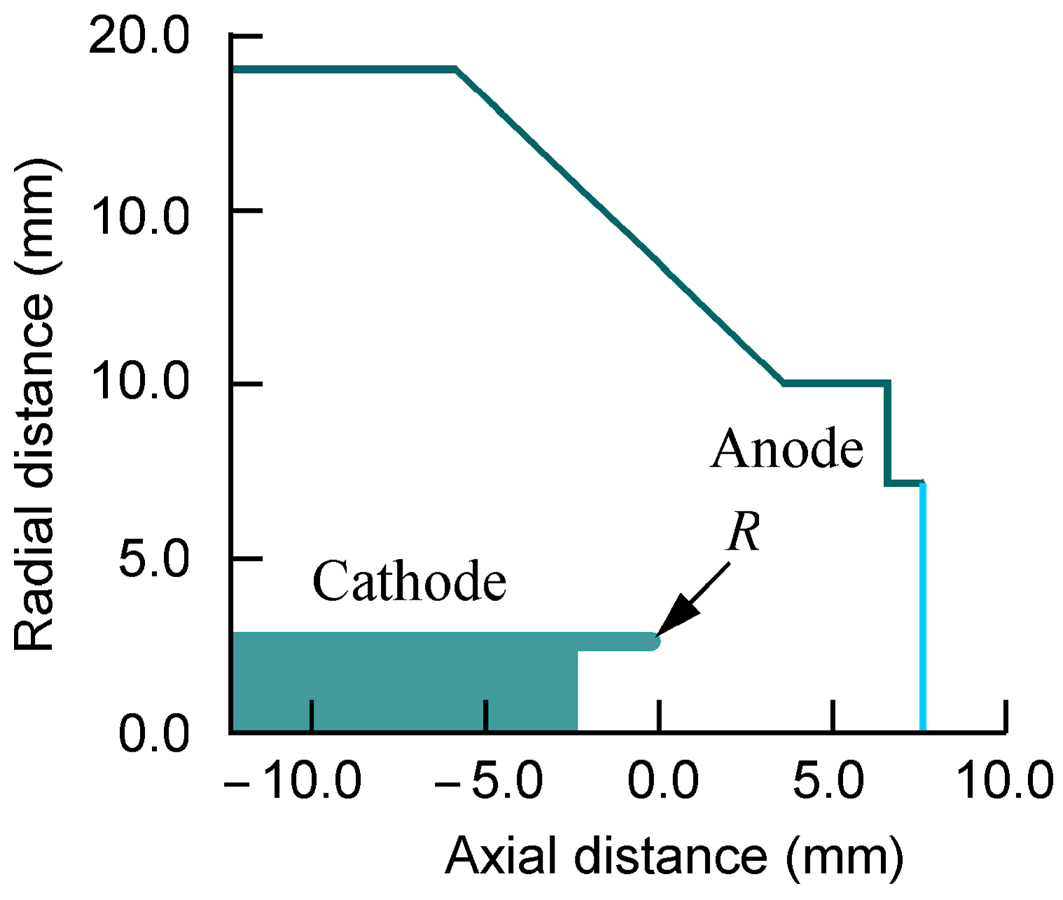
Consider a gas diode with a blade cathode: see
Figure 1. The origin of coordinates coincides with the cathode apex; the
x-axis lies in the plane of symmetry of the system, and the
y-axis is perpendicular to it. We use the parabolic approximation for the cathode shape,
x = −
y2/(2
R), where
R is the edge curvature radius. Since RAEs are generated at the initial stage of breakdown development, we can assume that the gas in the gap is not yet ionized, and the electric field distribution is not distorted by the volume electric charge. Then, the potential of the electric field
satisfies the Laplace equation with the condition of equipotentiality of the cathode surface (without loss of generality, this potential can be taken equal to zero). The corresponding solution is
where
D is the interelectrode distance,
U > 0 is the potential difference applied to the interelectrode gap, and
g is the auxiliary function given by the expression
We have
g =
R on the cathode surface and
g =
R + 2
D on the anode one. From general considerations, it is clear that the
x direction is the most appropriate for electron runaway. Therefore, to study the runaway conditions, that is, to determine the minimum voltage
U at which electrons begin to run away, it is sufficient to consider the one-dimensional problem of the motion of free electrons along the
x-axis. According to (1), the electric field potential
and the absolute value of the electric field strength
E on the
x-axis are given by the expressions
One can see from (3) that the field strength decreases monotonically with distance from the cathode with the asymptotics
(in this case,
). The electric field is maximum at the cathode, where its value is determined by the formula
Note that in the limit of an infinitely sharp blade, , the field strength at the cathode edge formally goes to infinity, .
The gap geometry in
Figure 1 is a convenient simplification of the real gap geometry “tubular edge cathode–flat anode” [
30,
31,
36] schematically shown in
Figure 2. In our experiments, gas diodes of this configuration were usually supplied by high-voltage subnanosecond generators developed on the basis of devices described in [
37,
38,
39,
40]. These generators have a low wave impedance (≈ 45 Ohm) and, therefore, “subthreshold” low-current processes (for instance, field emission) initiating gas ionization do not affect the voltage parameters. The diode remains a high-resistance (open-circuit) load for the generator until the gas becomes conductive due to the passage of RAEs, the subsequent ionization wave, and then the appearance of a discharge current. Since power is applied to the cathode in the traveling (TEM) wave mode, the generator voltage amplitude doubled here (in the idle mode). Usually, the RAE generation starts at the leading edge of the voltage pulse. The potential difference applied to the gap increases, and runaway conditions are reached sooner or later. The spread of the RAE emission onset time lies in the range of several tens of picoseconds. When a given gap voltage is required after the appearance of the initial RAEs (this situation is considered in the present paper), such a regime can be provided by adjusting the amplitude and shape of the voltage pulse. In this case, the time spread of the RAE appearance may increase, but there are special methods to reduce it [
41].
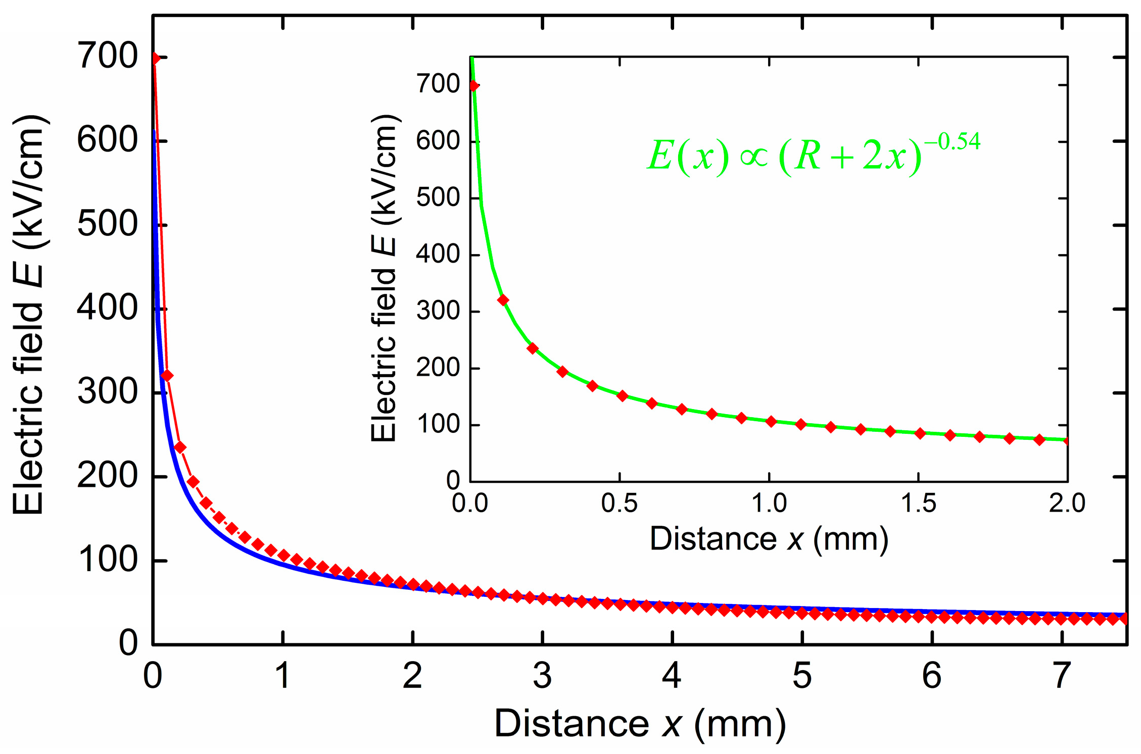
Formulas (1)–(4) adequately approximate the actual field distribution along the gap. So,
Figure 3 (red diamonds) shows the distribution of the electric field strength (in absolute value) between the edge of the tubular cathode and the anode (
U = 50 kV,
R = 50 μm,
D = 7.5 mm, the tubular cathode diameter is 6 mm) calculated by the SAM code [
42]. This distribution is sharply inhomogeneous. The field strength is ~700 kV/cm at the cathode edge, which is several times higher than the runaway threshold
Ec, and it drops to ~30 kV/cm near the anode, which is an order of magnitude lower than
Ec. For comparison, we also present the electric field distribution corresponding to formula (3): blue solid line in
Figure 3. As can be seen, the analytical approximation demonstrates a fairly high accuracy. The inset in
Figure 3 shows the calculated field distribution in the immediate vicinity of the cathode edge (i.e., in the region where the field distribution should be close to two-dimensional), as well as its approximation by the power law
Almost complete agreement is reached at the exponent
β = 0.54, i.e., at a value close to 0.5, corresponding to distribution (3). Note also that formula (4) gives ~610 kV/cm for the field strength at the cathode, and the best approximation with
β = 0.54 gives ~800 kV/cm. These values are close to the numerically calculated value of ~700 kV/cm near the cathode edge. All this testifies to the applicability of the simplified model geometry of the problem (
Figure 1) to the description of real experiments.
The equation of the one-dimensional motion of a free electron, written in terms of its kinetic energy
, has the following form [
3,
4,
5]:
where
f is the total force acting on the electron. Below, we solve Equation (5) with the initial condition
, which corresponds to the smallness of the initial electron energy compared to other scales (
εc,
eREc,
eU) in the problem. The first term in
f corresponds to the force acting on the electron from the electric field. The second term (
F) is the friction force for an electron moving through a gas. To find
F, we apply the nonrelativistic Bethe formula [
26,
43,
44,
45]. Using the quantities
Ec and
εc, it can be represented in the compact form
where 2.718 is the base of the natural logarithm. Note that for calculations in the region of thermal energies,
, instead of formula (6), which loses its physical meaning, we use the approximation
, which ensures the drift of an electron in a gas with fixed mobility.
By definition, RAE must continuously accelerate throughout the entire interelectrode gap. Thus, the runaway criterion is
and the runaway threshold corresponds to the minimum value (
Uc) of the applied potential difference at which condition (7) is satisfied. Condition (7) can be rewritten as
, where
is the minimum value of the force on the segment
. In
Section 4 and
Section 5, we show that, under near-threshold conditions, the minimum is reached in the near-anode region at relatively small
R and in the near-cathode region at large
R. This determines the different character and conditions of electron runaway for the cathodes with different degrees of sharpness.
3. Local Runaway Conditions (Analytics)
We call the runaway condition
local if the transition of an electron into the runaway mode is determined by its dynamics in the region where it originates, i.e., in our case, near the apex of the blade cathode. For example, in a weakly inhomogeneous field (
dE/
dx <<
U/
D2), the runaway condition for electrons starting at some point
x is the inequality
E(
x) >
Ec, i.e., it is local. If the electron does not become thermal in the vicinity of point
x, then it will certainly run away in the rest of the gap. As applied to the problem we are considering, this criterion has a simple form
E0 >
Ec. Taking into account (4), it is rewritten in terms of the voltage
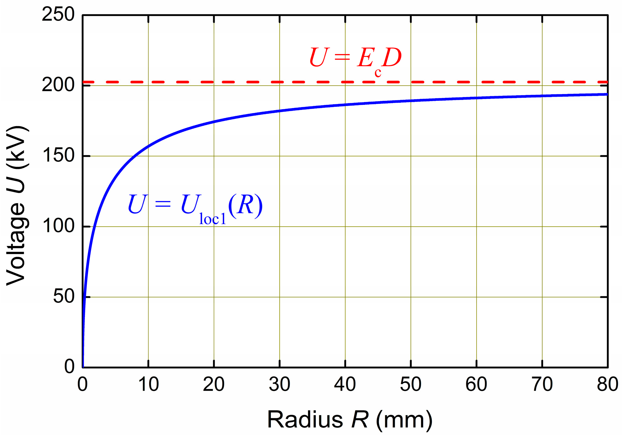
U as
The corresponding dependence of the threshold voltage
Uloc1 on the cathode curvature radius
R is given in
Figure 4. Here, we take
D = 7.5 mm, the gas is air at atmospheric pressure, which corresponds to the experimental conditions [
36]. Here and below, we take
and
for atmospheric air.
As can be seen from
Figure 4, the threshold voltage goes to a constant at large
R. This is due to the fact that, in this formal limit, the cathode and anode become flat, and the field in the gap becomes uniform and equal to
U/
D. Then, the classical runaway condition is applicable: the field strength must exceed the threshold
Ec, i.e.,
U/
D >
Ec. It is this condition in the form
that is realized for
. Note that for the parameters we use,
Ec D = 202.5 kV.
We are obviously more interested in the opposite limit of a very sharp cathode,
. One can see from
Figure 4 that
for
. This situation arises because, as discussed in
Section 2, the field strength at the edge
E0 formally tends to infinity for an infinitely sharp cathode at any nonzero voltage. From general considerations, it is clear that such a result has no physical meaning. It also contradicts the experimental data [
36], according to which, for a highly sharpened cathode (
), the threshold voltage remains finite and is estimated as 40–45 kV.
It is possible to propose a more adequate, remaining local criterion, based on the requirement that the condition
E >
Ec holds at some point
xc, where the electron gains the energy
εc and, according to the Bethe formula (6), the friction force is maximum. The position of this point without taking into account the energy losses of electrons in collisions with gas molecules (this approximation will be called “vacuum” in the following) is determined as
. Then, the runaway threshold (its lower estimate) is found from the condition
. Let us rewrite it in terms of voltage, denoting the corresponding threshold as
Uloc2. Using expressions (2) and (3) for the potential and strength distributions, we obtain the system of equations with two unknowns,
xc and
Uloc2:
The runaway criterion
U >
Uloc2 can be considered as local since the following inequality is true for
xc for any
R:
This gives , i.e., the point xc is located in the immediate vicinity of the cathode.
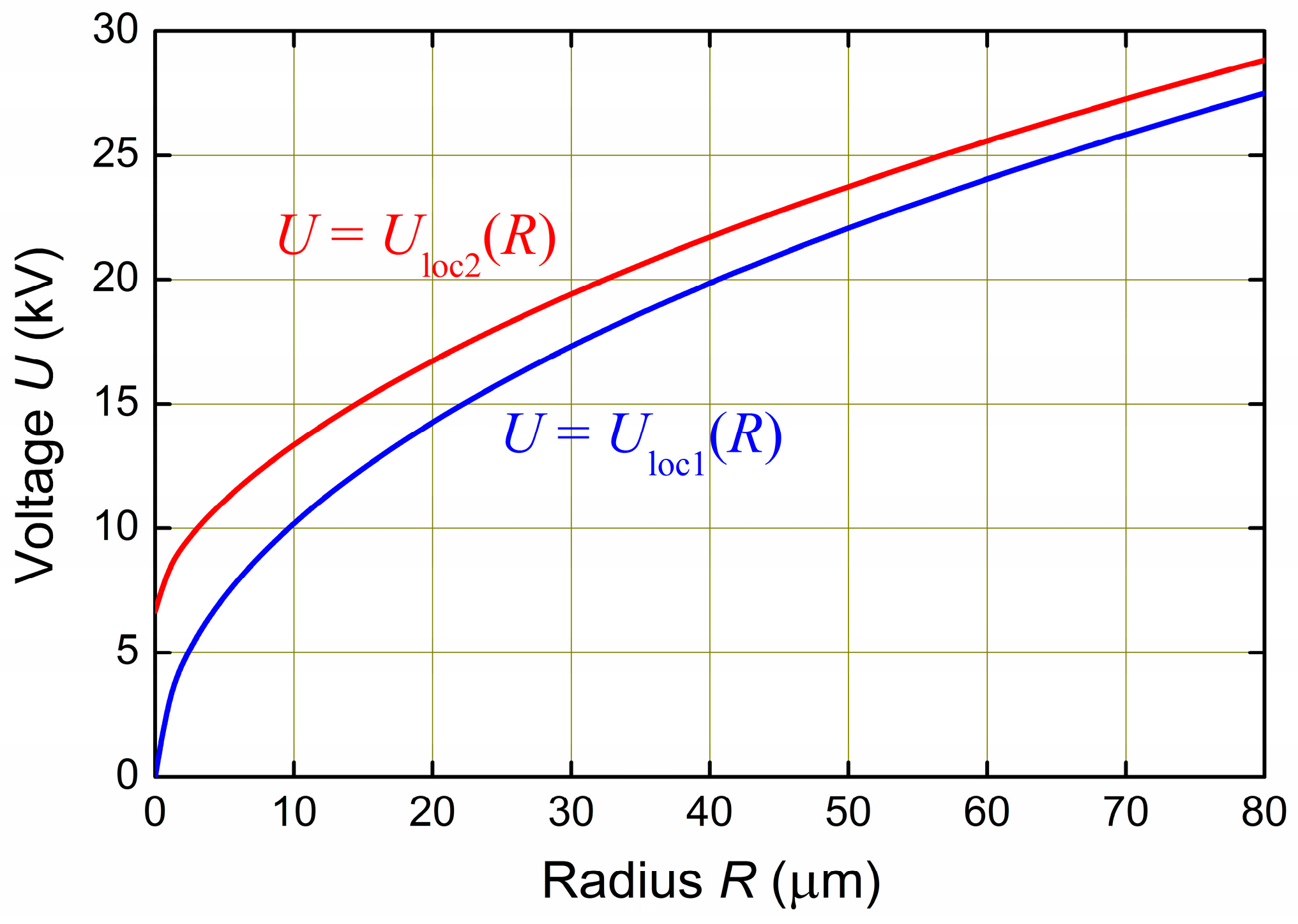
If we compare the expressions for
Uloc1 and
Uloc2, we see that noticeable differences should appear at
. For our parameters, this corresponds to the region
. Indeed,
Figure 5 shows the dependences of the threshold voltages
Uloc1 and
Uloc2 on the curvature radius
R. It can be seen that the relative differences between
Uloc1 and
Uloc2 are large at small radii and small at large radii. Unlike the first criterion, which gives
Uloc1 = 0 for
R = 0, the second criterion here gives the finite voltage value:
This result is more physical, but all the same, the voltage is almost an order of magnitude less than that recorded in the experiments [
30,
31] (40–45 kV for
). This means that local runaway criteria with different degrees of accuracy are unable to describe adequately the processes for highly sharpened cathodes. In this case, the criterion is not of a local nature, and the runaway threshold will be determined by processes not near the cathode but at the periphery. The reasons for this behavior of electrons will be discussed in the following
Section 4 and
Section 5.
4. Results of Numerical Simulations: Two Regimes of Electron Runaway
In this section, we present the results of the numerical solution of the one-dimensional Equation (5) of electron motion in a gas in the inhomogeneous electric field (3). It is assumed that the gas is atmospheric air (
Ec = 270 kV/cm and
εc = 110 eV);
D = 7.5 mm, which corresponds to the geometry of the gas diode used in the experiments [
36].
The equation of motion was solved on the segment
. The cathode curvature radius
R and the voltage
U applied to the gap were varied over a wide range. We analyzed the conditions under which an electron starting from the cathode will run away, i.e., continuously accelerate throughout the entire interelectrode gap. This regime of motion is realized when condition (7) is satisfied, i.e., when the total force acting on the electron is positive along the whole trajectory. The simulation results are shown in
Figure 6, where the boundary of the regions where free electrons run away and where they become thermal is plotted (red diamonds) on the parametric plane {
R,
U}. This boundary was determined as a result of varying
U at fixed
R; we searched for the minimum voltage values (
Uc), at which condition (7) was satisfied.
It can be seen from
Figure 6 that the value of
Uc monotonically increases with increasing radius
R. At
, this value is minimum and amounts to ~25.8 kV. In our works [
35,
36], it was indicated that
Uc must exceed a certain minimum value
determined by the equation
For our parameters, we get
, which somewhat exceeds the values of
Uc found by us numerically for small
R. The reason for this discrepancy is the use in [
35,
36] of a number of fairly crude simplifications: the logarithmic part of the Bethe formula was taken as a constant; conclusions about the runaway conditions were made on the basis of the electron dynamics at infinity,
, while in reality the trajectories are limited by the anode.
The calculated dependence
Uc(
R) is in rather good agreement with the results of numerical simulations of the electron runaway probability in a gas diode on the basis of the 2D Monte-Carlo technique and of 1D Boltzmann’s equation [
46,
47]. This proves the effectiveness of relatively simple and easy-to-analyze deterministic models of type (5), which, as it turns out, have comparable predictive power with much more complex probabilistic Monte-Carlo and kinetic models. Note that when comparing the results of different approaches, it is necessary to correct for different sets of elementary processes included in the models, for different gap geometry, as well as for the principal uncertainty in finding the runaway threshold for any probabilistic models.
We also note the qualitative agreement of our theoretical results with the experimental results of [
36], in which the threshold conditions for electron runaway for tubular cathodes of different edge radii (5, 50, 200 μm) were studied. It was established in [
36] that the fulfillment of the classical local runaway condition
E0 >
Ec is insufficient for the generation of RAEs in the case of a highly sharpened cathode. For a radius of 5 μm, RAEs were not recorded (i.e., the RAE current was lower than the noise level) for an applied voltage of up to 40 kV, despite the fact that the field at the cathode edge was several times higher than the critical value
Ec: the estimate by formula (4) gives ~1.5 MV/cm. A noticeable RAE flow appeared only at voltages of 40–45 kV. From our point of view, such a voltage threshold is determined by the electron dynamics at the periphery, in the near-anode region, i.e., in terms of this work, by the
nonlocal runaway condition. Our calculations give a comparable value of ~26 kV in the formal limit of
for
Ec = 270 kV/cm (if we take
Ec = 450 kV/cm as in [
35], then the value of
Uc will increase to 33–34 kV). The higher values of
Uc in the experiments can be associated with the use of ultrashort voltage pulses, for which peak voltage values were maintained for less than 100 ps. This, accounting for the limited emissivity of the cathode, as well as a certain inertia of the process of reproduction of free electrons in the near-cathode region (see, for example, [
13,
17,
18]), inevitably leads to an increase in the required voltage.
The blue line in
Figure 6 shows the boundary corresponding to the local runaway criterion (8), i.e., to the classical condition that the field
E0 must exceed the threshold value
Ec. It can be seen that, for relatively large
R, the local criterion qualitatively correctly describes the numerically calculated shape of the boundary. On the contrary, for a very sharp cathode (i.e., for small
R), the local criterion is clearly inapplicable. There is a qualitative difference in the dependences
Uc(
R) and
Uloc1(
R). At
, the threshold voltage
Uc is finite, while
Uloc1 vanishes.
In order to understand the reasons for this discrepancy, one should analyze the distributions of the total force
f acting on an electron in the interelectrode gap
. It is convenient to introduce the dimensionless force normalized by
eE,
which for RAEs is always in the range 0 <
fn < 1. In
Figure 7a–c, the red lines show characteristic dependences
fn(
x) for
R = 25, 38, 50 μm at threshold voltages
U =
Uc (~29.01, 30.83, 32.65 kV, respectively). The runaway threshold, as can be seen, corresponds to the situation where
fn is positive everywhere except for the single point
x =
D, where
fn = 0. From this, we can conclude that it is important to analyze the behavior of an electron near the anode. Moreover, one might get the impression that the behavior of an electron near the anode will determine the runaway threshold for any
R. However, this conclusion is not true. The fact is that the regime of electron motion corresponding to the threshold
U =
Uc is not always stable and the corresponding dependences
fn(
x) do not give a complete picture of the RAE dynamics.
Let us consider the motion of electrons at relatively small deviations
of the voltage applied to the gap from the threshold
Uc (in the problem under consideration, the combination
gives the smallest scale for the potential difference; we have
). The corresponding near-threshold dependences
fn(
x) are shown by green and blue lines in
Figure 7a–c. Comparing them, we can conclude that the character of the electron behavior differs for blade cathodes with different degrees of sharpness. In the first case (for the smallest value of the curvature radius
R = 25 μm,
Figure 7a), the shape of the dependencies changes smoothly, without qualitative transformations as the parameter
U varies. At
U <
Uc, the force
fn becomes negative in the immediate vicinity of the anode and, consequently, here the electron slows down. At
U >
Uc, the force
fn at the anode becomes positive, but its absolute minimum is still here. There is also a shallow local minimum of
fn near the cathode, however, it obviously does not determine the runaway threshold. It is clear that, in the case under discussion, the “bottleneck” for the runaway of electrons is located in the near-anode region.
In the latter case (for the largest value of the radius
R = 50 μm,
Figure 7c), the critical regime of electron motion is unstable. Relatively small variations in the applied voltage lead to radical changes in the shape of the dependences
fn(
x). At
U <
Uc, the force
fn becomes negative at a relatively small distance (hundreds of microns) from the cathode. A free electron loses energy, becomes thermal, and begins to drift relatively slowly towards the anode. At
U >
Uc, the shape of the dependence
fn(
x) changes qualitatively. The minimum of the force near the anode disappears. There remains a single local minimum of the force
fn near the cathode (at a distance of tens of microns), and, as can be seen from the comparison with the subcritical regime, it is the passage of this minimum that determines the electron runaway threshold. In this case, the “bottleneck” for electron runaway is located in the near-cathode region and, therefore, local runaway criteria can be applied.
The transition between two qualitatively different regimes of electron runaway, where the runaway threshold is determined by the particle dynamics in the near-anode (
Figure 7a) or near-cathode (
Figure 7c) regions, occurs approximately at
R =
Rc = 38 μm, i.e., falls within the range of scales used in the experiments [
36]. As can be seen from the dependences presented in
Figure 7b, the depths of both minima of the normalized force
fn coincide at
U =
Uc +
εc/
e, and the role of the near-anode and near-cathode regions for determining the runaway threshold is comparable.
Thus, our analysis showed that at R < Rc (this corresponds to highly sharpened blade cathodes), the runaway threshold is not determined by processes near the cathode, and, consequently, local runaway criteria are inapplicable. In this situation, it is necessary to analyze the motion of an electron in the entire gap , and the corresponding runaway conditions will be nonlocal.
5. Nonlocal Runaway Conditions (Analytics)
The above analysis indicates that the local runaway criteria based on consideration of the electron dynamics near the place of its origin, viz. the edge of the blade cathode, stop working in the case of a cathode with a small edge radius.
In this section, based on the method of successive approximations, we derive the necessary nonlocal runaway criterion that takes into account the dynamics of electrons in the entire gap. In the first, vacuum approximation, we neglect the friction force F. Then the energy of an electron is determined by the potential difference passed by it: . In the next approximation, we already take into account the influence of the friction force. Recall that it is determined by the kinetic energy of the electron ε. For an approximate calculation of F, we use the electron energy from the previous iteration, , i.e., take and, respectively, . It is clear from general considerations that always . According to the Bethe formula (6), the friction force decreases with increasing at and then the inequalities and are valid. Thus, we overestimate the total force acting on the electron. As a consequence, the runaway conditions obtained on the basis of the used approximations will underestimate the threshold values of the voltage U.
The normalized force acting on an electron in the described approximation is
where we used Formulas (2), (3), and (6). By analogy with (7), for an electron to run away, it is necessary that
fn(
x) > 0 for
.
Figure 8 shows the dependences of the normalized force
fn on
x corresponding to
U = 16.09 kV and
R = 14 μm (a);
U = 16.06 kV and
(b);
U = 16.94 kV and
R = 20 μm (c). It can be seen that these dependences have two minima: an extremum near the cathode at some point
x =
xmin and a minimum at the anode
x =
D, which is not an extremum. For an electron to run away, it is sufficient to fulfill two conditions for two existing minima:
fn(
xmin) > 0 and
fn(
D) > 0. The first condition, in fact, corresponds to the region where the electron originates (
xmin is in the near-cathode region) and, therefore, is local. The second condition corresponds to the periphery (near-anode region) and is nonlocal.
All dependences shown in
Figure 8a–c correspond to the runaway threshold (in the approximation used):
fn > 0 everywhere, except for individual points where
fn = 0. For
Figure 8a,
fn(
xmin) > 0 and
fn(
D) = 0, i.e., the runaway threshold is determined by the behavior of the electron near the anode, and it is required to use the nonlocal runaway condition. For
Figure 8c,
fn(
xmin) = 0 and
fn(
D) > 0, i.e., the runaway threshold is determined by the electron behavior near the cathode, and the local runaway condition is applicable. For
Figure 8b,
fn(
xmin) = 0 and
fn(
D) = 0, i.e., this is the intermediate case: the local and nonlocal runaway conditions give the same voltage thresholds
U. The boundary of applicability of the local and nonlocal criteria corresponds to the curvature radius of the cathode edge equal to ~16.95 μm. The nonlocal runaway criterion
fn(
D) > 0 will be stronger for smaller
R, and the local criterion
fn(
xmin) > 0 will be stronger for larger
R. Noticeable quantitative differences from the results of numerical simulations of the previous
Section 4 (in particular, differences in the value of
Rc) are associated with the use of fairly rough approximations in the present section, which, however, allow us to formulate the runaway conditions analytically.
The local criterion (
U >
Uloc3) is reduced to two equations for determining the values
xmin and
Uloc3 (extremum and threshold conditions, respectively):
After simple transformations, they lead to the system
Let us approximately resolve this transcendental equation with respect to
xmin, assuming that
and, as a consequence,
. By expanding in powers of the corresponding small quantity
, we find
Then, we get for the voltage threshold
Keeping only the first terms of the expansion, we obtain
It is noteworthy that such an expression for Uloc3 exactly coincides with the first local criterion (8), i.e., Uloc3 = Uloc1. For our parameters, , so the condition xmin << R reduces to R >> 4 μm. As already mentioned, (and will be confirmed analytically below), it is necessary to use another, nonlocal runaway condition for small R, so that the approximations used are valid in the region of applicability of the local condition.
Consider now the nonlocal runaway criterion
U >
Unl, where
Unl is the corresponding threshold. As shown above, this criterion should be related to the anode. Then, the runaway threshold is determined from the equality
It determines the threshold voltage
Unl as a solution of the equation
where we used (10). Let
R <<
D (this condition is certainly satisfied in the region of applicability of the nonlocal runaway criterion, viz. for very sharp cathodes). Then, taking into account the finiteness of
R, we obtain in the first nonvanishing order of the expansion in the parameter
R/
D:
Thus, for an electron to run away, two conditions must be met,
The question arises, which condition (local or nonlocal) will be stronger.
Figure 9 shows the dependences of
Uloc3 and
Unl on
R described by expressions (11) and (12) (green and magenta lines, respectively). It can be seen that
Unl >
Uloc3 for small
R, and the transition to runaway is determined by the electron behavior at the periphery (near the anode). On the contrary, for comparatively large
R,
Uloc3 >
Unl, and the transition will be determined by the behavior of the electron near the cathode. In
Figure 9, solid and dashed lines show stronger and weaker conditions, respectively. The boundary for applying different runaway conditions is found from the equality
Uloc3 =
Unl, which gives the radius
from the numerical analysis of the dependence
fn(
x) (
Figure 8b) and a close value
analytically, based on expressions (11) and (12) (black circle in
Figure 9). In this case, the approximation
R <<
D that we used is certainly satisfied in the region of applicability of the nonlocal criterion
R <
Rc. In addition, in the region of applicability of the local criterion
R >
Rc, the condition
used in its derivation is satisfied with sufficient accuracy.
For comparison with the analytical results,
Figure 9 also shows the results of numerical calculations of the threshold voltage from
Section 4 (red diamonds). The corresponding points predictably lie above the analytical dependencies, which provide necessary but insufficient runaway criteria. It can be seen that the results of numerical and analytical calculations are in qualitative agreement: the threshold voltage values are comparable for any
R. The maximum differences correspond to relatively small
R. So, at
R = 0, we have
and
, i.e., the voltages differ by one and a half times. The threshold radius
Rc, found numerically in
Section 4, is ~38 μm (black diamond in
Figure 9), and the one found analytically is about half as much, ~17 μm (black circle). Such differences are obviously associated with the use of the method of successive approximations, within which, at the first step, the RAE energy was calculated without taking into account energy losses. This assumption is quite valid when the runaway threshold is significantly exceeded but is a rough approximation in the near-threshold regime. Nevertheless, the analytical theory agrees with numerical calculations in the main: it also demonstrates the inapplicability of local runaway criteria at small
R and, in contrast to the classical local criterion, gives a finite value of the threshold voltage in the limit
. We also note that the local runaway criterion (the dependence
Uloc3(
R) in
Figure 9) refined in this section approximates the numerical dependence
Uc(
R) noticeably better than the curve
Uloc1(
R) corresponding to the classical local criterion
E0 >
Ec (dashed blue line). At the same time, the dependences
Uloc3(
R) and
Uloc1(
R) practically coincide at large
R.
Let us now discuss the factors on which the scale of
Rc depends. In the main order of expansion in terms of the parameters
Rc/
D and
, we analytically find from the condition
Uloc3 =
Unl:
From this, we can conclude that
Rc only weakly (logarithmically) depends on the gap geometry and strongly depends on the quantities
Ec and
εc, which are, in fact, characteristics of the gas. It is possible to take approximately
. Due to the linear dependence of
Ec on the gas concentration and, therefore, on its pressure
p [
27,
28,
48], the relation
is valid. Then, the threshold value of the radius increases with decreasing gas pressure. This means that the range of parameters in which the nonlocal criterion introduced by us will determine the transition to runaway expands with decreasing
p (it should be noted that with increasing pressure, a number of other factors appear that affect the transition of electrons into the runaway mode [
28,
49,
50,
51,
52]). Such an analysis emphasizes the usefulness of the obtained analytical relations, despite their approximate character. The derived analytical formulas make it possible to predict the behavior of runaway electrons in a wide range of parameters and, as a result, to develop gas diodes with the required characteristics without resorting to time-consuming numerical calculations.

