Abstract
Recently, orthogonal time frequency space modulation with index modulation (OTFS-IM) has been proposed to improve the bit-error-rate (BER) performance of the OTFS system. However, only some of the grids in the OTFS-IM system are activated, resulting in low spectral efficiency (SE). In order to solve this problem, a new scheme called multiple-mode OTFS-IM (MM-OTFS-IM) is proposed in this paper. In the proposed scheme, all grids are activated to transmit modulation bits. Each grid in the subblock adopts a different modulation mode, and the index bits are transmitted implicitly by the combination of different constellation modes. At the receiver, a distance-based signal detection algorithm is designed, which uses the distance matrix to find the combination of the minimum sum of elements to recover the index bits. The simulation results demonstrate the enhanced performance of the proposed scheme in the time-varying channels.
1. Introduction
The orthogonal frequency division multiplexing (OFDM) modulation technique widely used in the fourth-generation (4G) and fifth-generation (5G) mobile communications is a multicarrier modulation technology. OFDM improves the spectral efficiency of the system by taking advantage of the orthogonal characteristics between the subcarriers of the system. However, the orthogonality of the OFDM subcarriers is severely damaged due to the Doppler frequency shift in fast time-varying channels, which leads to poor system performance. With the increasing demand for the reliability and spectral efficiency of communication systems, future multicarrier modulation schemes are expected to resist channel effects in time-varying channels [].
The recently proposed orthogonal time-frequency spatial (OTFS) modulation technology has attracted extensive attention as a two-dimensional modulation method in the delay-Doppler (DD) domain []. OTFS is an effective waveform for signaling over time-varying channels that takes advantage of the time diversity to improve the reliability of wireliess links. Each signal modulated in the DD domain will experience almost the same fading to achieve full-time and full-frequency diversity gains. In high-speed mobile scenarios, OTFS can achieve better performance than OFDM [,]. OTFS modulation is a generalized signaling framework, which can be regarded as an extension of the traditional time-frequency modulation scheme, that is, adding preprocessing and postprocessing modules based on the traditional time-frequency modulation scheme. In OTFS, transmit symbols are treated as the values of the regularly spaced grids in the DD domain. The transformation step takes each symbol and extends it to the entire time-frequency (TF) domain. The result of this transformation is then passed on to a multicarrier system for modulation and transmission. In this way, all symbols are equally affected by the channel frequency selectivity and time diversity, so that the time-varying channel is transformed into a unified time-invariant impulse response in the DD domain for all the symbols under a good approximation. To recover the transmitted symbols at the receiver, the respective multicarrier demodulation followed by an inverse transformation step takes the received signal back to the DD domain. In the preprocessing and postprocessing, inverse symplectic finite Fourier transform (ISFFT) and symplectic finite Fourier transform (SFFT) are used to realize the conversion of signals between the DD domain and the TF domain [].
Index modulation (IM) is a new information transmission technology; unlike traditional modulation techniques, index modulation can transmit additional information without additional energy consumption by utilizing the switch or call state of the transmission resource. Index modulation expands the switch or calls a state of transmission resources into a new transmission dimension to transmit additional information such as antennas, subcarriers, spreading codes, and time slots []. Therefore, index modulation only needs to activate a part of the transmission resources to achieve the same throughput as the traditional modulation scheme. Index modulation not only reduces the energy consumption during information transmission but also improves the energy efficiency of the system. At the same time, because only some transmission resources are activated, the signal shows a certain sparsity after index modulation. This sparsity weakens the interference between transmission signals in a certain extent and improves the anti-interference performance of the system []. On the other hand, the index bits of the implicit transmission are transmitted without energy consumption. Index modulation transfers the energy saved from the unactivated transmission resources to the activated transmission resources. Therefore, index modulation can achieve a better bit error rate (BER) performance on the premise of transmitting the same energy.
Index modulation in the frequency domain is usually performed with the aid of either the frequency carriers or OFDM subcarriers. OFDM with an index modulation (OFDM-IM) system improves the spectrum efficiency (SE) of the OFDM system and achieves better performance [,]. The OFDM-IM system activates only a subset of all avaliable subcarriers to carry M-ary data symbols and uses the subcarrier activation patterns as information-bearing units. In [], an OTFS with an index modulation (OTFS-IM) system was proposed. The OTFS-IM system transmits modulation bits by activating partial grid resources and transmits index information by using the location information of activated grid points. Although the OTFS-IM system achieves better BER performance, only some of the grid resources are activated, resulting in the waste of grid resources and a low SE of the system []. An OTFS with improved index modulation (OTFS-IIM) was proposed in []. Unlike the OTFS-IM system, each index information is transmitted twice in the OTFS-IIM system, which reduces the error rate of the index bits and further improves the BER performance. However, the problem of grid resource waste has not been solved. To solve this problem, an OTFS with dual-mode index modulation (OTFS-DM-IM) was proposed []. In the OTFS-DM-IM system, all grid resources are activated for transmitting modulation bits, achieving a better balance between transmission reliability and SE in the time-varying channel. Moreover, the theoretical BER upper bound was presented to give the benchmark of the OTFS-DM-IM system.
In this paper, to improve the SE and energy efficiency (EE) of the OTFS-IM system, a multiple-mode index modulation-aided OTFS system (MM-OTFS-IM) is proposed. In this system, the grid resources of OTFS were divided into several subblocks, and each grid resource in the subblocks carries the modulation information of different constellation modes and uses the combination of different constellation modes to transmit the index information. Then, a signal detection algorithm based on distance was designed at the receiver. After that, the SE, EE, and computational complexity of the receiver signal detection algorithm of the MM-OTFS-IM system were analyzed. Finally, the BER performance of the MM-OTFS-IM system was compared with that of the OTFS, OTFS-IM, and OTFS-DM-IM systems in the time-varying channel to verify the superiority of the MM-OTFS-IM system.
2. System Model
2.1. The Transmitter
We considered an MM-OTFS-IM system with M subcarriers and N symbols, where the subcarrier spacing and symbol duration are and T, respectively. The block diagram of the MM-OTFS-IM transmitter is depicted in Figure 1. At each time instant, a number of p bits arrive to the transmitter and are equally split into g groups with bits in each group. Each group of bits is then divided into bits and bits, separately referred to as index bits and information bits, to generate an OTFS subblock containing s points on the DD domain, where s = MN/g. N and M are the number of resource units along the Doppler dimension and delay dimension, respectively. As shown in Figure 1, the first bits flow into the index selector to select the constellation mode carrying the modulation information of each grid point resource in the subblock, and the remaining bits are the multi-constellation modulation information carried by all grid point resources in the subblock. The size of each subblock is s = mn, where the number of grids along the delay dimension of the subblock is m, and the number of grids along the Doppler dimension is n. The frame architecture of the MM-OTFS-IM in the DD domain is shown in Figure 2; the left side is the signal frame of the MM-OTFS-IM system in the DD domain, which is composed of g subblocks, and the structure of each subblock is shown on the right side of Figure 2, each grid in the subblock carries the modulation signal of a different constellation mode.
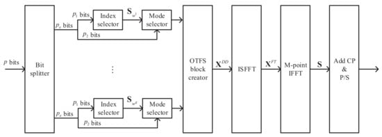
Figure 1.
Block diagram of the MM-OTFS-IM transmitter.
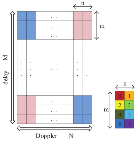
Figure 2.
Frame architecture of the MM-OTFS-IM in the DD domain.
Since each subblock has the same processing procedure, for brevity, we take the -th subblock as an example, where . The index selector determines the order of elements in set according to the incoming bits and obtains the combination information of different constellation patterns adopted by grids in the subblock
where represents the constellation mode adopted by the i-th lattice point in the -th subblock, and the average power of has been normalized to unit power. The remaining bits use the corresponding constellation mode to generate modulation signals.
To achieve index modulation, the different constellation modes need to satisfy , where , . By rotating the constellation diagram of -ary phase shift keying (PSK) mn times, where the rotation angle is , the signal constellations of -ary PSK with different modes can be obtained []. Figure 3 shows the BPSK signal constellation diagram of eight different modes, which is obtained by rotating the original BPSK signal constellation eight times. Therefore, and can be calculated as and , where is the floor function.
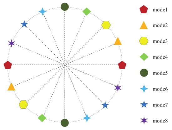
Figure 3.
BPSK signal constellation of eight different modes.
Afterward, the OTFS block creator generates the DD domain signal of all the subblocks
where , and . Then, at the transmitter, the data symbols are first converted to the TF domain through the ISFFT operation, which can be written in a matrix form as
where , , and are fast Fourier transform (FFT) matrices, and denotes the conjugate transpose of a matrix. Then, the time domain signal is obtained by the M-point inverse fast Fourier transform (IFFT), which can be written as
To avoid intersymbol interference (ISI) between OTFS blocks, a cyclic prefix (CP) is appended to the front of before transmission. The 1D transmit signal can be written as
where is a CP addition matrix, is the length of CP, and the operation is a vectorization operator to a matrix.
2.2. The Receiver
As shown in Figure 4, the received signal over the time-varying channel is first rearranged as a matrix . Then, we removes the CP by multiplying with a CP removal matrix to obtain the MM-OTFS-IM symbols without CPs. Next, by applying the M-point FFT on each MM-OTFS-IM symbol, we obtain the received 2D block in the TF domain as
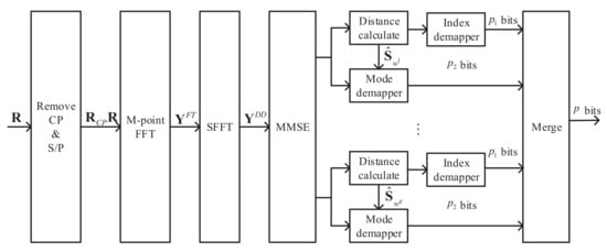
Figure 4.
Block diagram of the MM-OTFS-IM receiver.
Then, the SFFT is applied for to obtain the 2D data block in the DD domain as
In addition, the input–output relationship of the MM-OTFS-IM system can be written as
where , , is the channel matrix in the DD domain, and is the additive white Gaussian noise (AWGN).
To recover the sending information from , the receiver first determines the constellation mode adopted by each grid in the subblock. To recover the index bits and the modulation bits according to the combined information of the constellation modes, a signal detection algorithm based on a distance matrix is proposed.
Firstly, the minimum mean square error (MMSE) method is required to equalize the received signal before using the detection algorithm.
where is the MMSE equalized signal in the DD domain, which is the estimate of , is the average signal to noise ratio (SNR) in the DD domain, and denotes the inverse of a matrix. Then, we can obtain the estimate of as , where the operation is the antioperation of . Next, is divided into g subblocks as , which are expressed as
The proposed signal detection algorithm is depicted in Algorithm 1, in which the input is first converted into a one-dimensional vector . Then, the modulation information matrix and distance matrix are recovered by a double-layer nested loop. The specific operation is as follows: we use constellation mode to demodulate symbol to obtain , which is the element at the position of the j-th row in the i-th column of matrix . Then, is used to demodulate . To calculate the distance between the modulated symbol and symbol , it obtains the element , which is the element at the position of the j-th row in the i-th column of matrix . At the end of the cycle, the algorithm is used to process the distance matrix and obtain the index information of the subblocks. When only one element can appear in each row and column of a matrix, the algorithm can find the position information of each element when the sum of elements is minimum. Finally, the modulation bits and index bits of the subblock are recovered by the modulation information matrix and index mapping information .
| Algorithm 1: Detecting algorithm. |
| Input:, m, and n Output: and
|
3. System Performance Analysis
3.1. SE Analysis
Generally, SE is defined as the ratio of the system transmission bit rate to the total bandwidth occupied by the transmission symbol. The duration of a single MM-OTFS-IM signal frame is , the spectrum bandwidth occupied is , and the number of transmitted bits is . Therefore, the SE of the MM-OTFS-IM system is
With the same parameters, the SE of the OTFS, OTFS-IM, and OTFS-DM-IM systems are expressed as
where k represents the number of selected grids in the subblock, is the modulation order of the signals in the selected grids of the OTFS-DM-IM system, and is the modulation order of signals in the unselected grids.
In the OTFS system, all grids are activated to transmit information with the same modulation mode, so the SE of the OTFS system is only related to the modulation order. The SEs of the OTFS-IM, OTFS-DM-IM, and MM-OTFS-IM systems are related to the subblock structure due to the index modulation. In the OTFS-IM system, only some of the grids are activated, so the SE is low. The OTFS-DM-IM and MM-OTFS-IM systems transmit some additional index bits by activating all grids, so these two systems achieve higher SE. The OTFS-DM-IM system can carry extra bits per subblock. The number of additional bits of MM-OTFS-IM each subblock is . By comparison, the MM-OTFS-IM system can carry more extra bits.
3.2. EE Analysis
The EE of a communication system is defined as the number of transmitted information bits per unit of energy. The number of transmitted information bits of each subblock in the MM-OTFS-IM signal frame is , where are the number of index bits, which do not need to consume energy resources, and are the modulation bits, which consumes s units of energy. Therefore, the energy efficiency of the MM-OTFS-IM system can be obtained
Under the same parameter conditions, the EE of the OTFS, OTFS-IM, and OTFS-DM-IM systems can be expressed as
Due to the application of the index modulation, compared with the OTFS system, the EE of the OTFS-IM, OTFS-DM-IM, and MM-OTFS-IM systems improved to some extent. At the same time, the EE of the OTFS-IM, OTFS-DM-IM, and MM-OTFS-IM systems is not only related to the modulation order of the constellation signal but also the subblock structure of the signal frame. When the constellation signal modulation order is the same, the MM-OTFS-IM system can transmit the most index bits, so the MM-OTFS-IM system can achieve a higher EE.
3.3. The Complexity of the Receiver
The complexity of the receiver signal detection algorithm consists of two parts. The first part is the complexity of the MMSE algorithm for equalizing received signals []. The second part is the complexity of recovering index bits and modulation bits from each subblocks. According to the description of the signal detection algorithm in Section 2, the computational complexity of constellation demodulation is , and the computational complexity of the double layer nested loop is . The algorithm has a computational complexity of []. Therefore, the computational complexity of each subblock of the signal detection algorithm is . If the maximum likelihood (ML) detection algorithm is adopted, the computational complexity of each subblock is . Compared with the ML detection algorithm, the computational complexity of the proposed signal detection algorithm is effectively reduced, and it is a low complexity signal detection algorithm.
4. Simulation Results and Discussion
In this section, we present the simulation results for the proposed MM-OTFS-IM scheme over time-varying channels with different configurations compared with the classical OTFS, OTFS-IM and OTFS-DM-IM. A channel with p = 5 paths was used in the simulation, where the Doppler profile was given by with as the maximum Doppler shift and , and the delay profile is defined in Table 1. The maximum Doppler shift was determined by the user equipment (UE) speed, when the UE speed was 120 km/h, 300 km/h, and 500 km/h with carrier frequency 4 GHz, the corresponding maximum Doppler shift was Hz, 300 Hz, and 1850 Hz respectively. The other simulation parameters used are given in Table 2 and Table 3.

Table 1.
Delay profile of channel (p = 5) for simulations.
Table 2.
Simulation parameters.
Table 3.
System parameters of the compared systems.
In Figure 5, we compare the BER performance of the proposed MM-OTFS-IM system with the OTFS-IM system under different SEs. It can be seen from Figure 5 that when the SE was 1.5 bps/Hz and 2.5 bps/Hz, the BER performance of the MM-OTFS-IM system was better than that of the OTFS-IM system. For example, when the SE was 2.5 bps/Hz, the MM-OTFS-IM system achieved a performance gain of 2 dB compared to the OTFS-IM system at the BER level of . When the SE was 1.5 bps/Hz, the MM-OTFS-IM system achieved a 5 dB gain over the OTFS-IM system at the BER level of . Under the same SE, the MM-OTFS-IM system used a lower order constellation to modulate the transmission symbols, which resulted in a larger Euclidean distance between the transmission symbols; thus, the BER performance of the proposed system was improved.
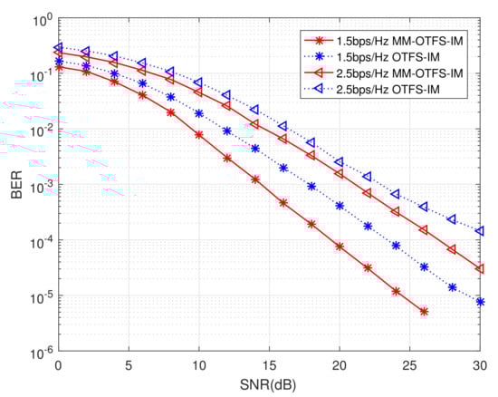
Figure 5.
BER performance comparison between the MM-OTFS-IM and the OTFS-IM systems under different SEs.
The BER performance comparisons between the MM-OTFS-IM, the OTFS, the OTFS-IM, and the OTFS-DM-IM system with SEs of 3, 4, and 5 bps/Hz are shown in Figure 6, Figure 7 and Figure 8, respectively. Both the OTFS-IM and the OTFS-DM-IM system used M-PSK and M-QAM modulation modes, and the OTFS and the MM-OTFS-IM system used M-PSK modulation. The MM-OTFS-IM system obtained the best BER performance compared with the traditional OTFS, OTFS-IM, and OTFS-DM-IM systems with the same spectral efficiency at a high SNR region when using M-PSK modulation and the OTFS-IM with M-QAM. Under the same spectral efficiency, the BER performance of the OTFS-DM-IM system was slightly better than that of the MM-OTFS-IM system when M-QAM modulation was used. This is because the noise produces strong interference on the transmitted signals at a low SNR region. Thus, the application of index modulation causes a high occurrence probability of index bits detection error during demodulation, resulting in the BER performance of OTFS-IM, OTFS-DM-IM, and MM-OTFS-IM systems being worse than that of the OTFS systems. Under the condition of a high SNR region, because all grid points in the MM-OTFS-IM system were activated, and a large number of index bits were transmitted implicitly through the combination of different modes of the constellation, the BER performance of the MM-OTFS-IM system was improved.
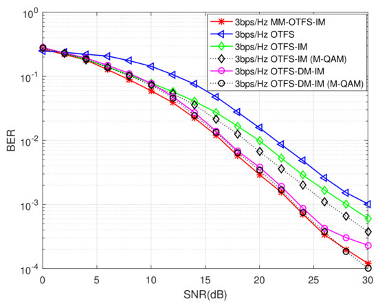
Figure 6.
BER performance comparison between the MM-OTFS-IM, OTFS, the OTFS-IM, and the OTFS-DM-IM systems under SE with 3 bps/Hz.
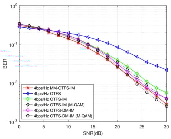
Figure 7.
BER performance comparison between the MM-OTFS-IM, OTFS, OTFS-IM, and the OTFS-DM-IM systems under SE with 4 bps/Hz.
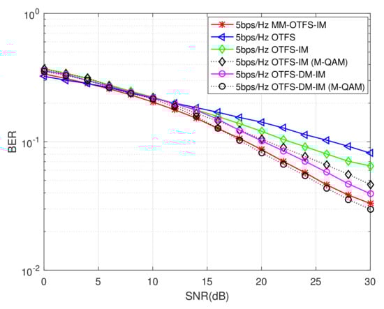
Figure 8.
BER performance comparison between the MM-OTFS-IM, OTFS, OTFS-IM, and the OTFS-DM-IM systems under SE with 5 bps/Hz.
Figure 9 shows the effect of different UE speeds on the BER performance of the proposed MM-OTFS-IM systems. In the figure, the SE of the MM-OTFS-IM system is 4 bps/Hz, and the speed of the UE is 120 km/h, 300 km/h and 500 km/h, respectively. As can be seen from the figure, under the condition of low SNR, the BER performance of the MM-OTFS-IM system was almost the same under different UE speeds, while the BER performance of the MM-OTFS-IM system decreased with the increase in the UE speeds at high SNRs. The reason is that the noise produced serious interference to the transmitted symbols for low SNRs, which resulted in a high error probability of index detection. At this time, the impact of noise on the system performance was far greater than that of the user equipment speed. For high SNRs, the influence of noise on the system performance was light, and the influence of the UE speed on the system performance gradually appeared. The increase in the UE speed led to the increase in the Doppler frequency offset, which aggravated the interference between transmitted symbols. That affected the index detection and symbol demodulation and reduced the BER performance of the system. Therefore, the increase in the UE speed led to the deterioration of the system BER performance.
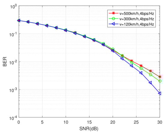
Figure 9.
BER performance of the MM-OTFS-IM system under different UE speeds.
5. Conclusions
Aiming at the problem of grid resource waste in the OTFS-IM system, this paper proposed a multiple-mode OTFS-IM system, namely the MM-OTFS-IM system. In the proposed system, each grid was modulated by the constellation of different modes, and the combination of different mode constellations was used to transmit index bits implicitly. By comparing the SE, EE, and computational complexity of the proposed system with other competitors, the proposed system showed a higher SE performance. The performance comparisons between the MM-OTFS-IM system with that of the OTFS, OTFS-IM, and OTFS-DM-IM systems validated that the proposed MM-OTFS-IM system achieved better BER performance under the same SE in time-varying channels.
Author Contributions
Conceptualization, H.R. and W.X.; methodology, H.R., W.X. and L.W.; software, H.R. and W.X.; validation, H.R. and W.X.; formal analysis, H.R. and L.W.; writing—original draft preparation, H.R.; writing—review and editing, H.R., W.X. and L.W.; visualization, H.R.; supervision, W.X.; project administration, L.W.; funding acquisition, W.X. All authors have read and agreed to the published version of the manuscript.
Funding
The National Natural Science Foundation of China (No. 61871337).
Institutional Review Board Statement
Not applicable.
Informed Consent Statement
Not applicable.
Data Availability Statement
Not applicable.
Conflicts of Interest
The authors declare no conflict of interest.
References
- Hadani, R.; Monk, A. OTFS: A new generation of modulation addressing the challenges of 5G. arXiv 2018, arXiv:1802.02623. [Google Scholar]
- Hadani, R.; Rakib, S.; Tsatsanis, M.; Monk, A.; Goldsmith, A.; Molisch, A.F.; Calderbank, R. Orthogonal Time Frequency Space Modulation. In Proceedings of the 2017 IEEE Wireless Communication and Networking Conference (WCNC), San Francisco, CA, USA, 19–22 March 2017; pp. 1–6. [Google Scholar]
- Surabhi, G.D.; Augustine, R.M.; Chockalingam, A. On the diversity of uncoded OTFS modulation in doubly-dispersive channels. IEEE Trans. Wirel. Commun. 2019, 18, 3049–3063. [Google Scholar] [CrossRef]
- Raviteja, P.; Phan, K.T.; Hong, Y.; Viterbo, E. Interference cancellation and iterative detection for orthogonal time frequency space modulation. IEEE Trans. Wirel. Commun. 2018, 17, 6501–6515. [Google Scholar] [CrossRef]
- Raviteja, P.; Hong, Y.; Viterbo, E.; Biglieri, E. Practical pulse-shaping waveforms for reduced-cyclic-prefix OTFS. IEEE Trans. Veh. Technol. 2018, 68, 957–961. [Google Scholar] [CrossRef]
- Di Renzo, M.; Haas, H.; Grant, P.M. Spatial modulation for multiple antenna wireless systems: A survey. IEEE Commun. Mag. 2011, 49, 182–191. [Google Scholar] [CrossRef]
- Mao, T.; Wang, Q.; Wang, Z.; Chen, S. Novel index modulation techniques: A survey. IEEE Commun. Surv. Tutor. 2019, 21, 315–348. [Google Scholar] [CrossRef]
- Basar, E.; Aygolu, U.; Panayirci, E.; Poor, H.V. Orthogonal frequency division multiplexing with index modulation. IEEE Trans. Sign. Process. 2013, 61, 5536–5549. [Google Scholar] [CrossRef]
- Zhang, X.; Bie, H.; Ye, Q.; Lei, C.; Tang, X. Dual-mode index modulation aided OFDM with constellation power allocation and low complexity detector design. IEEE Access 2017, 5, 23871–23880. [Google Scholar] [CrossRef]
- Liang, Y.; Li, L.; Fan, P.; Guan, Y. Doppler resilient orthogonal time-frequency space (OTFS) systems based on index modulation. In Proceedings of the IEEE 91st Vehicular Technology Conference (VTC2020-Spring), Antwerp, Belgium, 25–28 May 2020; pp. 1–5. [Google Scholar]
- Francis, J.K.; Augustine, R.M.; Chockalingam, A. Diversity and PAPR enhancement in OTFS using indexing. In Proceedings of the IEEE 93st Vehicular Technology Conference (VTC2021-Spring), Helsinki, Finland, 25–28 April 2021; pp. 1–5. [Google Scholar]
- Ren, H.; Xu, W.; Wang, L. Orthogonal Time-Frequency Space with Improved Index Modulation. In Proceedings of the 2021 15th International Conference on Signal Processing and Communication Systems (ICSPCS), 13–15 December 2021; pp. 1–6. [Google Scholar]
- Fu, J.; Hou, C.; Xiang, W.; Yan, L.; Hou, Y. Orthogonal time frequency space (OTFS) with dual-mode index modulation. IEEE Wirel. Commun. Lett. 2021, 10, 991–995. [Google Scholar]
- Wen, M.; Basar, E.; Li, Q.; Zheng, B.; Zhang, M. Multiple-Mode Orthogonal Frequency Division Multiplexing with Index Modulation. IEEE Trans. Commun. 2017, 65, 3892–3906. [Google Scholar] [CrossRef]
- Raviteja, P.; Viterbo, E.; Hong, Y. OTFS performance on static multipath channels. IEEE Wirel. Commun. Lett. 2019, 8, 745–748. [Google Scholar] [CrossRef]
- Chopra, S.; Notarstefano, G.; Rice, M.; Egerstedt, M. A Distributed Version of the Hungarian Method for Multirobot Assignment. IEEE Trans. Robot. 2017, 33, 932–947. [Google Scholar] [CrossRef]
Publisher’s Note: MDPI stays neutral with regard to jurisdictional claims in published maps and institutional affiliations. |
© 2022 by the authors. Licensee MDPI, Basel, Switzerland. This article is an open access article distributed under the terms and conditions of the Creative Commons Attribution (CC BY) license (https://creativecommons.org/licenses/by/4.0/).