
Functionally Graded Piezoelectric Energy Harvester: A Numerical Study

 ,
,
Abstract
:1. Introduction
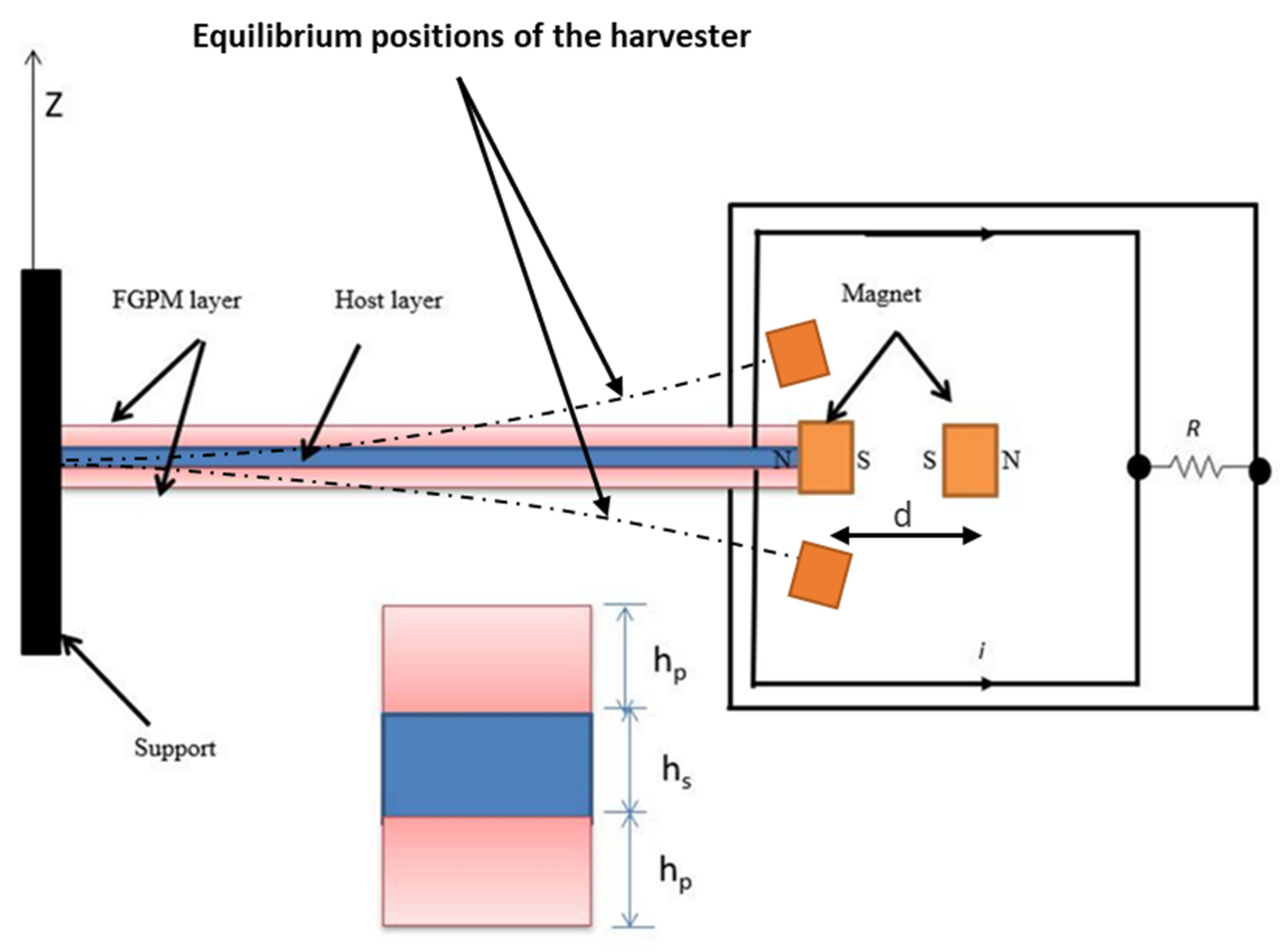
2. Formulation of Functionally Graded Piezoelectric Material Nonlinear Energy Harvester
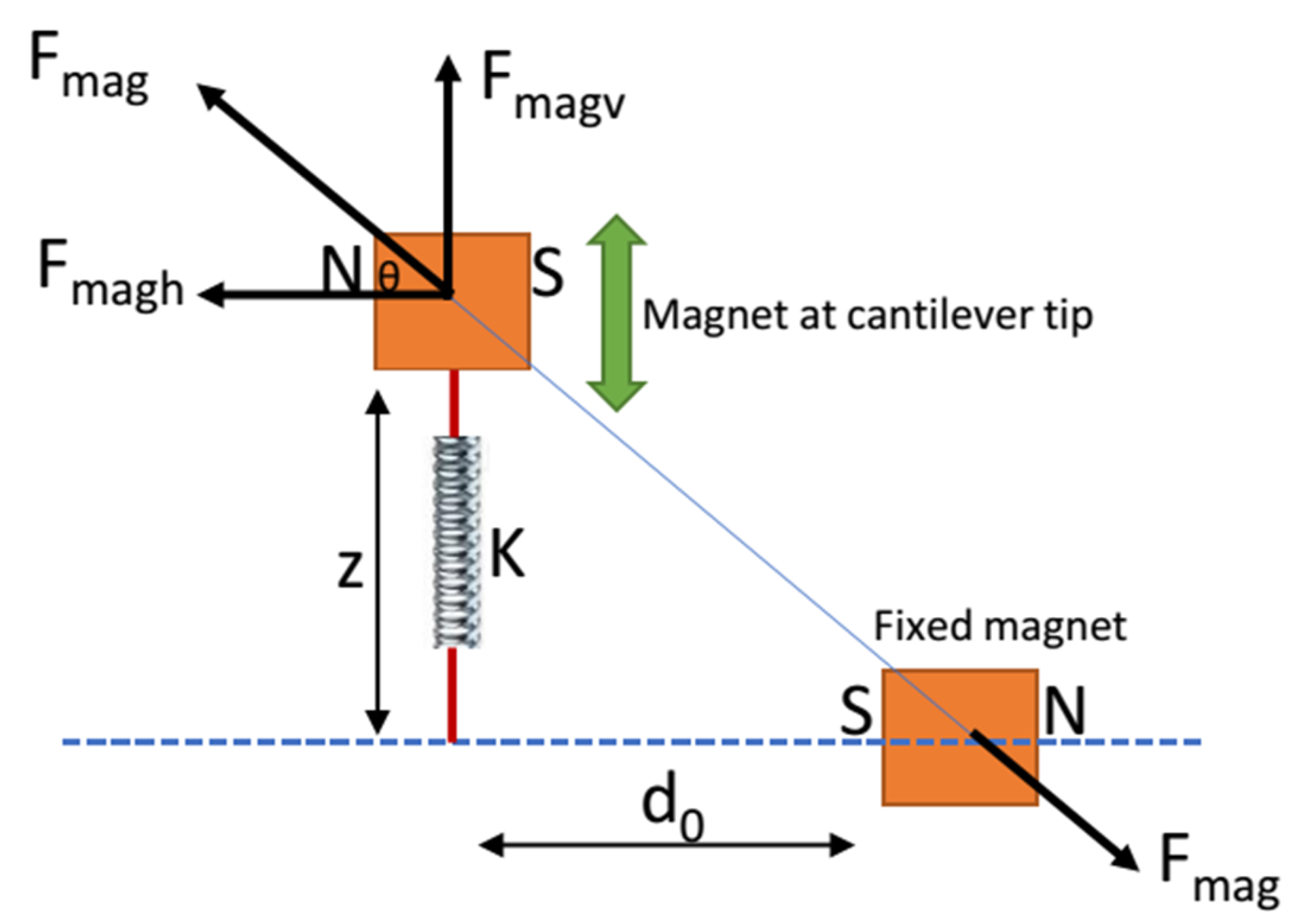
2.1. Modeling of the Magnetic Force:
2.2. Finite Element Formulation
2.3. Harmonic Balance Method
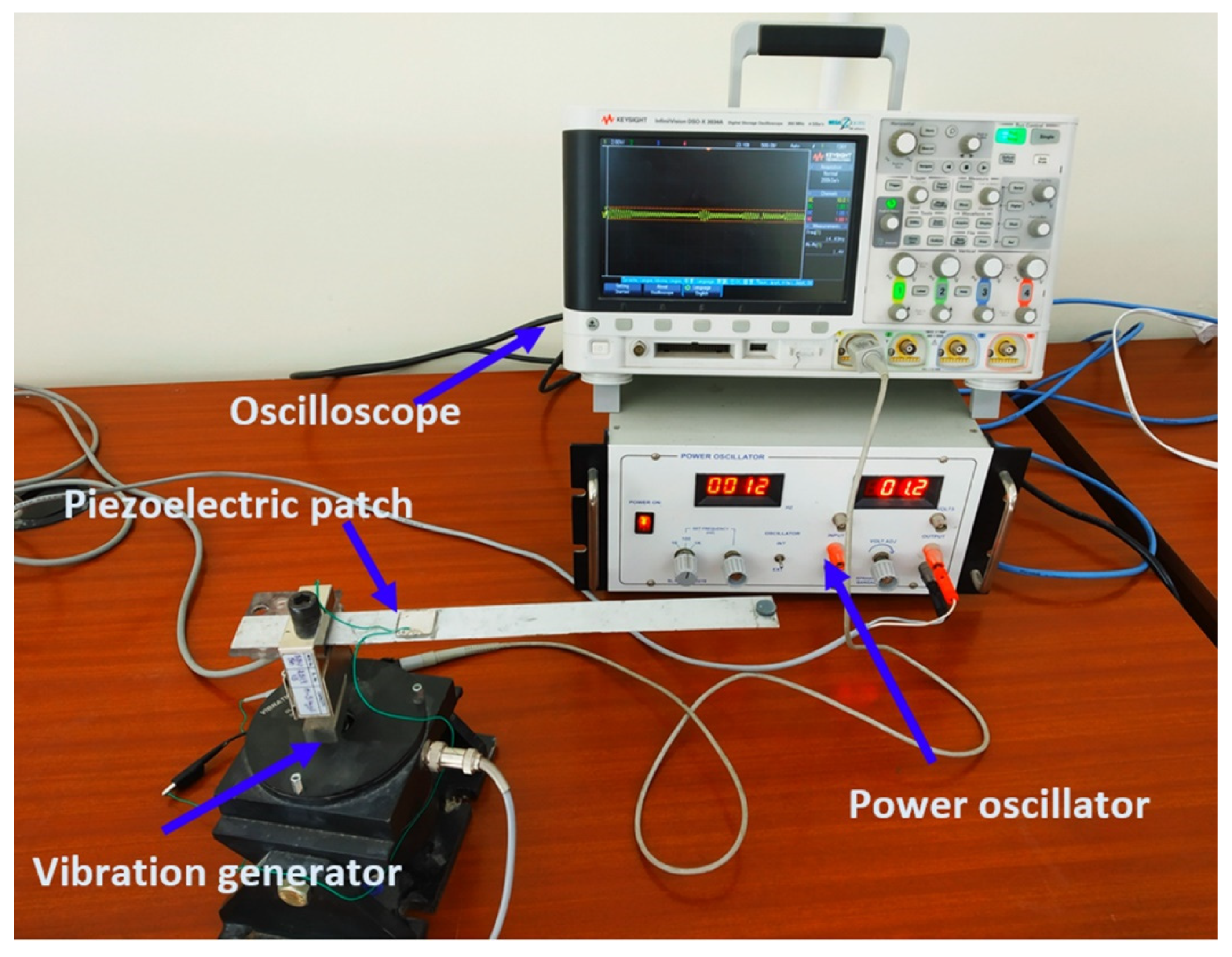
3. Validation Studies
3.1. Validation of Magnetic Force
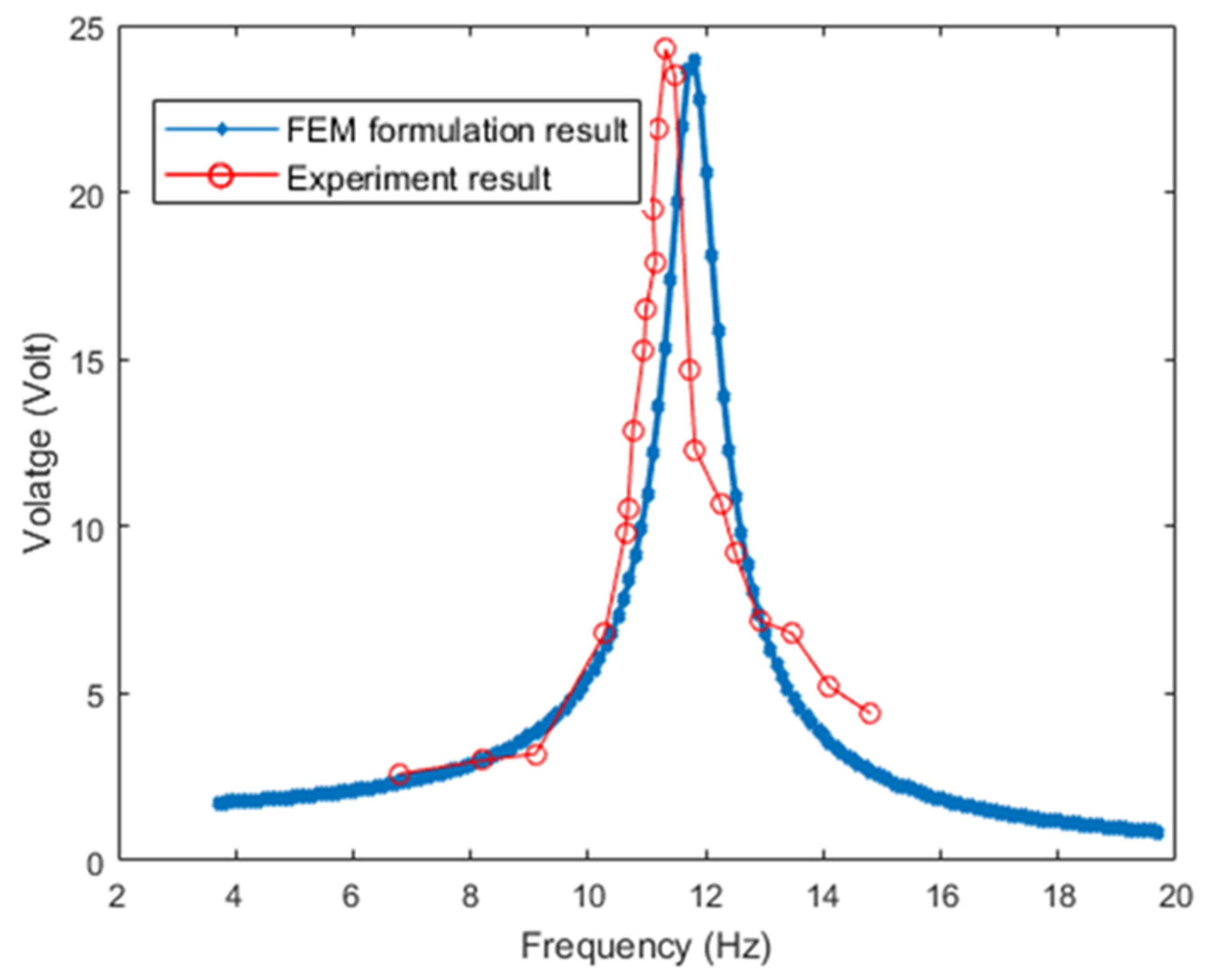
3.2. Validation of Open Circuit Voltage from Harvester
3.3. Validation of Simple Harmonic Balance Method
4. Numerical Studies
5. Conclusions
Author Contributions
Funding
Institutional Review Board Statement
Informed Consent Statement
Data Availability Statement
Conflicts of Interest
References
- Arrieta, A.F.; Hagedorn, P.; Erturk, A.; Inman, D.J. A piezoelectric bistable plate for nonlinear broadband energy harvesting. Appl. Phys. Lett. 2010, 97, 104102. [Google Scholar] [CrossRef]
- Challa, V.R.; Prasad, M.G.; Shi, Y.; Fisher, F.T. A vibration energy harvesting device with bidirectional resonance frequency tunability. Smart Mater. Struct. 2008, 17, 015035. [Google Scholar] [CrossRef]
- Iliuk, I.; Brasil, R.M.L.R.D.F.; Balthazar, J.M.; Tusset, A.M.; Piccirillo, V.; Piqueira, J.R.C. Potential Application in Energy Harvesting of Intermodal Energy Exchange in a Frame: FEM Analysis. Int. J. Struct. Stab. Dyn. 2014, 14, 1440027. [Google Scholar] [CrossRef]
- Mann, B.; Owens, B. Investigations of a nonlinear energy harvester with a bistable potential well. J. Sound Vib. 2010, 329, 1215–1226. [Google Scholar] [CrossRef]
- Zhu, D.; Tudor, M.J.; Beeby, S. Strategies for increasing the operating frequency range of vibration energy harvesters: A review. Meas. Sci. Technol. 2009, 21, 22001. [Google Scholar] [CrossRef]
- Mann, B.; Sims, N. Energy harvesting from the nonlinear oscillations of magnetic levitation. J. Sound Vib. 2009, 319, 515–530. [Google Scholar] [CrossRef]
- Ramlan, R.; Brennan, M.J.; Mace, B.R.; Kovacic, I. Potential benefits of a non-linear stiffness in an energy harvesting device. Nonlinear Dyn. 2010, 59, 545–558. [Google Scholar] [CrossRef]
- Daqaq, M.F. Response of uni-modal duffing-type harvesters to random forced excitations. J. Sound Vib. 2010, 329, 3621–3631. [Google Scholar] [CrossRef]
- Stanton, S.C.; Erturk, A.; Mann, B.; Inman, D.J. Nonlinear piezoelectricity in electroelastic energy harvesters: Modeling and experimental identification. J. Appl. Phys. 2010, 108, 074903. [Google Scholar] [CrossRef]
- Fan, K.-Q.; Chao, F.-B.; Zhang, J.-G.; Wang, W.-D.; Che, X.-H. Design and experimental verification of a bi-directional nonlinear piezoelectric energy harvester. Energy Convers. Manag. 2014, 86, 561–567. [Google Scholar] [CrossRef]
- Qiu, J.; Tani, J.; Ueno, T.; Morita, T.; Takahashi, H.; Du, H. Fabrication and high durability of functionally graded piezoelectric bending actuators. Smart Mater. Struct. 2003, 12, 115–121. [Google Scholar] [CrossRef]
- Chen, W.Q.; Ding, H.J. On free vibration of a functionally graded piezoelectric rectangular plate. Acta Mech. 2002, 153, 207–216. [Google Scholar] [CrossRef]
- Yang, J.; Xiang, H. Thermo-electro-mechanical characteristics of functionally graded piezoelectric actuators. Smart Mater. Struct. 2007, 16, 784–797. [Google Scholar] [CrossRef]
- Li, C.; Weng, G. Antiplane crack problem in functionally graded piezoelectric materials. J. Appl. Mech. 2002, 69, 481–488. [Google Scholar] [CrossRef]
- Rajasekaran, S. Free vibration of centrifugally stiffened axially functionally graded tapered Timoshenko beams using differential transformation and quadrature methods. Appl. Math. Model. 2013, 37, 4440–4463. [Google Scholar] [CrossRef]
- Takagi, K.; Li, J.-F.; Yokoyama, S.; Watanabe, R. Fabrication and evaluation of PZT/Pt piezoelectric composites and functionally graded actuators. J. Eur. Ceram. Soc. 2003, 23, 1577–1583. [Google Scholar] [CrossRef]
- Rafiee, M.; He, X.Q.; Liew, K.M. Nonlinear analysis of piezoelectric nanocomposite energy harvesting plates. Smart Mater. Struct. 2014, 23, 65001. [Google Scholar] [CrossRef]
- Amini, Y.; Fatehi, P.; Heshmati, M.; Parandvar, H. Time domain and frequency domain analysis of functionally graded piezoelectric harvesters subjected to random vibration: Finite element modeling. Compos. Struct. 2016, 136, 384–393. [Google Scholar] [CrossRef]
- Ng, T.Y.; He, X.; Liew, K.M. Finite element modeling of active control of functionally graded shells in frequency domain via piezoelectric sensors and actuators. Comput. Mech. 2002, 28, 1–9. [Google Scholar] [CrossRef]
- Amini, Y.; Emdad, H.; Farid, M. Finite element modeling of functionally graded piezoelectric harvesters. Compos. Struct. 2015, 129, 165–176. [Google Scholar] [CrossRef]
- Pradyumna, S.; Bandyopadhyay, J. Free vibration analysis of functionally graded curved panels using a higher-order finite element formulation. J. Sound Vib. 2008, 318, 176–192. [Google Scholar] [CrossRef]
- Susheel, C.K.; Kumar, R.; Chauhan, V.S. Active shape and vibration control of functionally graded thin plate using functionally graded piezoelectric material. J. Intell. Mater. Syst. Struct. 2016, 28, 1789–1802. [Google Scholar] [CrossRef]
- Kumar, T.; Kumar, R.; Chauhan, V.S.; Twiefel, J. Finite-Element Analysis of a Varying-Width Bistable Piezoelectric Energy Harvester. Energy Technol. 2015, 3, 1243–1249. [Google Scholar] [CrossRef]
- Xie, Z.; Kwuimy, C.A.K.; Wang, T.; Ding, X.; Huang, W. Theoretical analysis of an impact-bistable piezoelectric energy harvester. Eur. Phys. J. Plus 2019, 134, 190. [Google Scholar] [CrossRef]
- Erturk, A.; Inman, D.J. An experimentally validated bimorph cantilever model for piezoelectric energy harvesting from base excitations. Smart Mater. Struct. 2009, 18, 025009. [Google Scholar] [CrossRef]
- Sebald, G.; Kuwano, H.; Guyomar, D.; Ducharne, B. Experimental Duffing oscillator for broadband piezoelectric energy harvesting. Smart Mater. Struct. 2011, 20, 102001. [Google Scholar] [CrossRef]
- Stanton, S.C.; Owens, B.A.; Mann, B.P. Harmonic balance analysis of the bistable piezoelectric inertial generator. J. Sound Vib. 2012, 331, 3617–3627. [Google Scholar] [CrossRef]
- Al-Ashtari, W.; Hunstig, M.; Hemsel, T.; Sextro, W. Frequency tuning of piezoelectric energy harvesters by magnetic force. Smart Mater. Struct. 2012, 21, 035019. [Google Scholar] [CrossRef]
- Marathe, A.; Govindarajan, R. Nonlinear Dynamical Systems, Their Stability, and Chaos Lecture notes from the FLOW-NORDITA Summer School on Advanced Instability Methods for Complex Flows, Stockholm, Sweden, 2013. Appl. Mech. Rev. 2014, 66, 24802. [Google Scholar] [CrossRef]


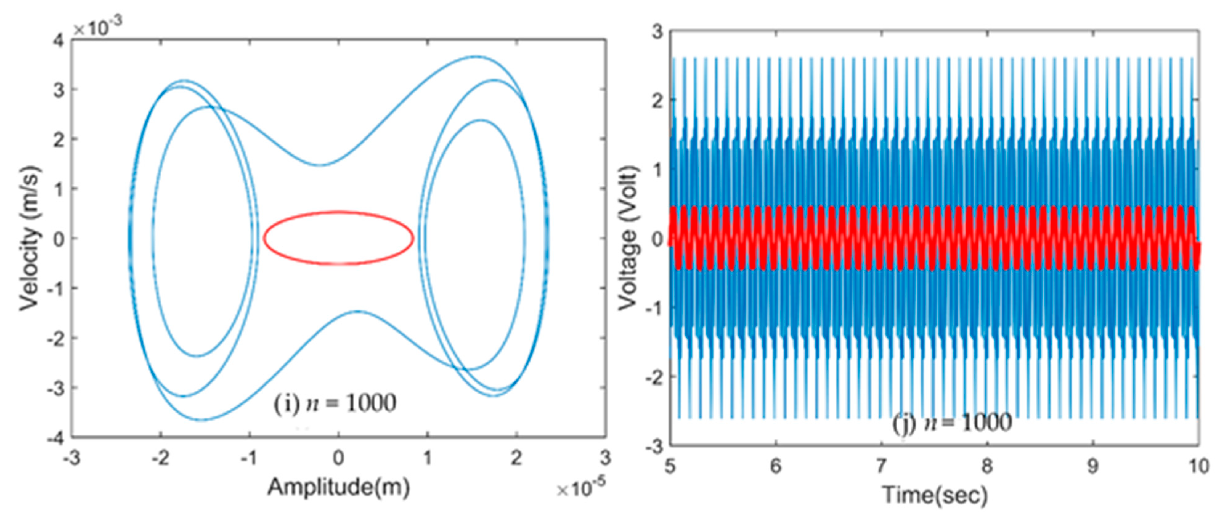
 Linear harvester,
  Non Linear harvester). (a,b) at n = 0; (c,d) at n = 0.5; (e,f) at n = 1; (g,h) at n = 2; (i,j) at n = 1000.
Linear harvester, Non Linear harvester). (a,b) at n = 0; (c,d) at n = 0.5; (e,f) at n = 1; (g,h) at n = 2; (i,j) at n = 1000.
Non Linear harvester). (a,b) at n = 0; (c,d) at n = 0.5; (e,f) at n = 1; (g,h) at n = 2; (i,j) at n = 1000.
Linear harvester, Non Linear harvester). (a,b) at n = 0; (c,d) at n = 0.5; (e,f) at n = 1; (g,h) at n = 2; (i,j) at n = 1000.


| Distance (mm) | Magnetic Force (N) (Reference) | Magnetic Force (N) (Present) |
|---|---|---|
| 0 | 18.47 | 18.44 |
| 3 | 3.558 | 3.555 |
| 6 | 1.239 | 1.234 |
| 9 | 0.552 | 0.540 |
| 10 | 0.4473 | 0.4471 |
| Geometrical Parameters | Value |
|---|---|
| Length of the cantilever beam | 250 mm |
| Width of beam | 25 mm |
| Thickness of beam | 0.5 mm |
| Length of Piezoelectric patch | 20 mm |
| Width of piezoelectric patch | 20 mm |
| Thickness of the piezoelectric layer | 0.5 mm |
| Distance of piezoelectric patch from fixed end | 50 mm |
| Geometrical Parameters | Value |
|---|---|
| Length of the cantilever beam | 150 mm |
| Width of beam | 6 mm |
| Thickness of host layer | 1 mm |
| Thickness of the piezoelectric layer | 0.5 mm |
| Material Properties | PZT-0% Pt | PZT-20% Pt | Aluminum |
|---|---|---|---|
| Young’s modulus, Y (GPa) | 63 | 84.8 | 70 |
| Density, ρ (kg/m3) | 7500 | 10,290 | 2707 |
| Poisson’s ratio, υ | 0.3 | 0.342 | 0.3 |
| Piezoelectric constant, d31 (pC/N) | −164 | −98 | Conductive layer |
| Dielectric constant (at constant stress), ε33/εo | 1653 | 2927 | Conductive layer |
| d0 (mm) | n = 0 | n = 0.5 | n = 1 | n = 2 | n = 1000 | |||||
|---|---|---|---|---|---|---|---|---|---|---|
| Voltage (V) | Power (mW) | Voltage (V) | Power (mW) | Voltage (V) | Power (mW) | Voltage (V) | Power (mW) | Voltage (V) | Power (mW) | |
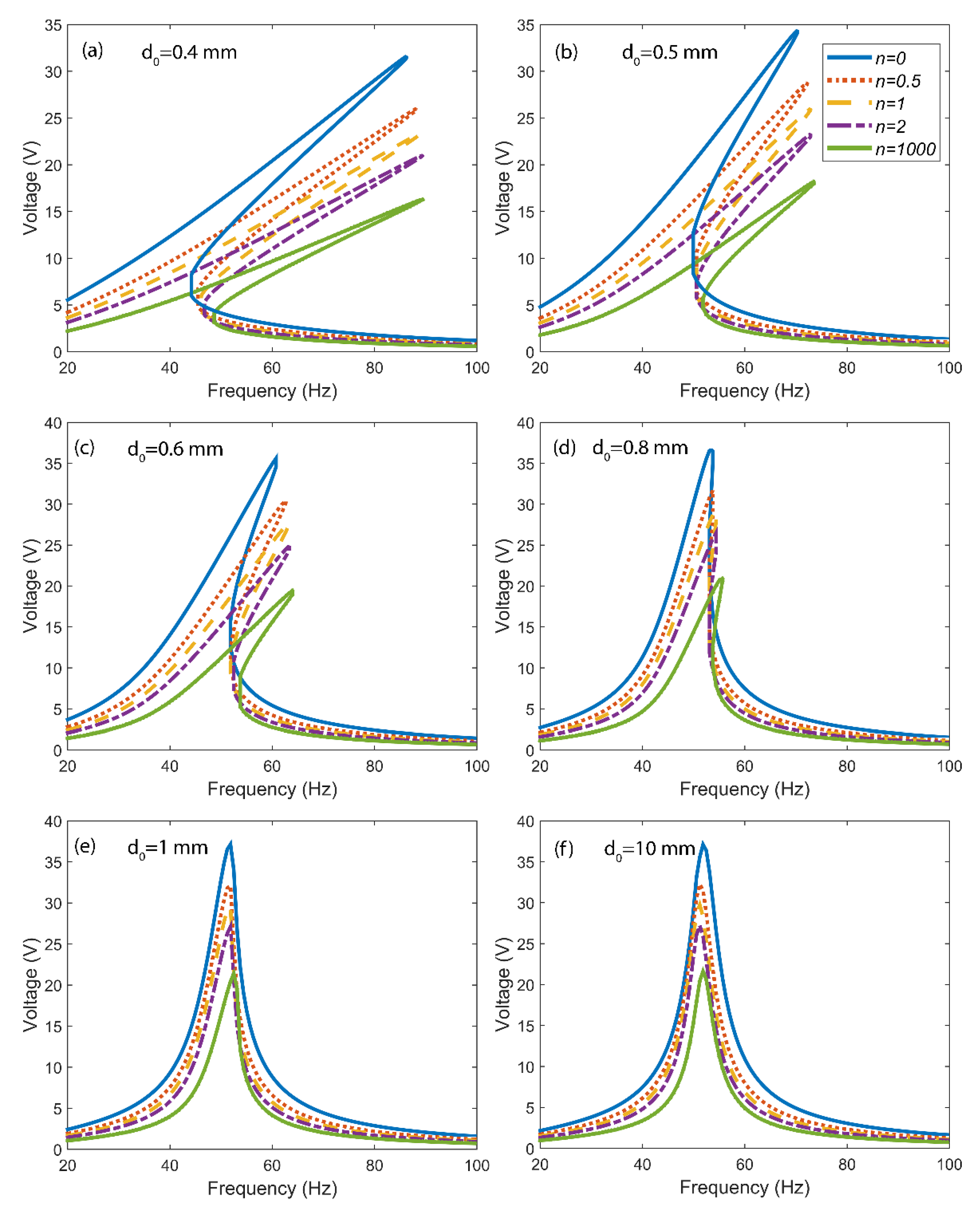
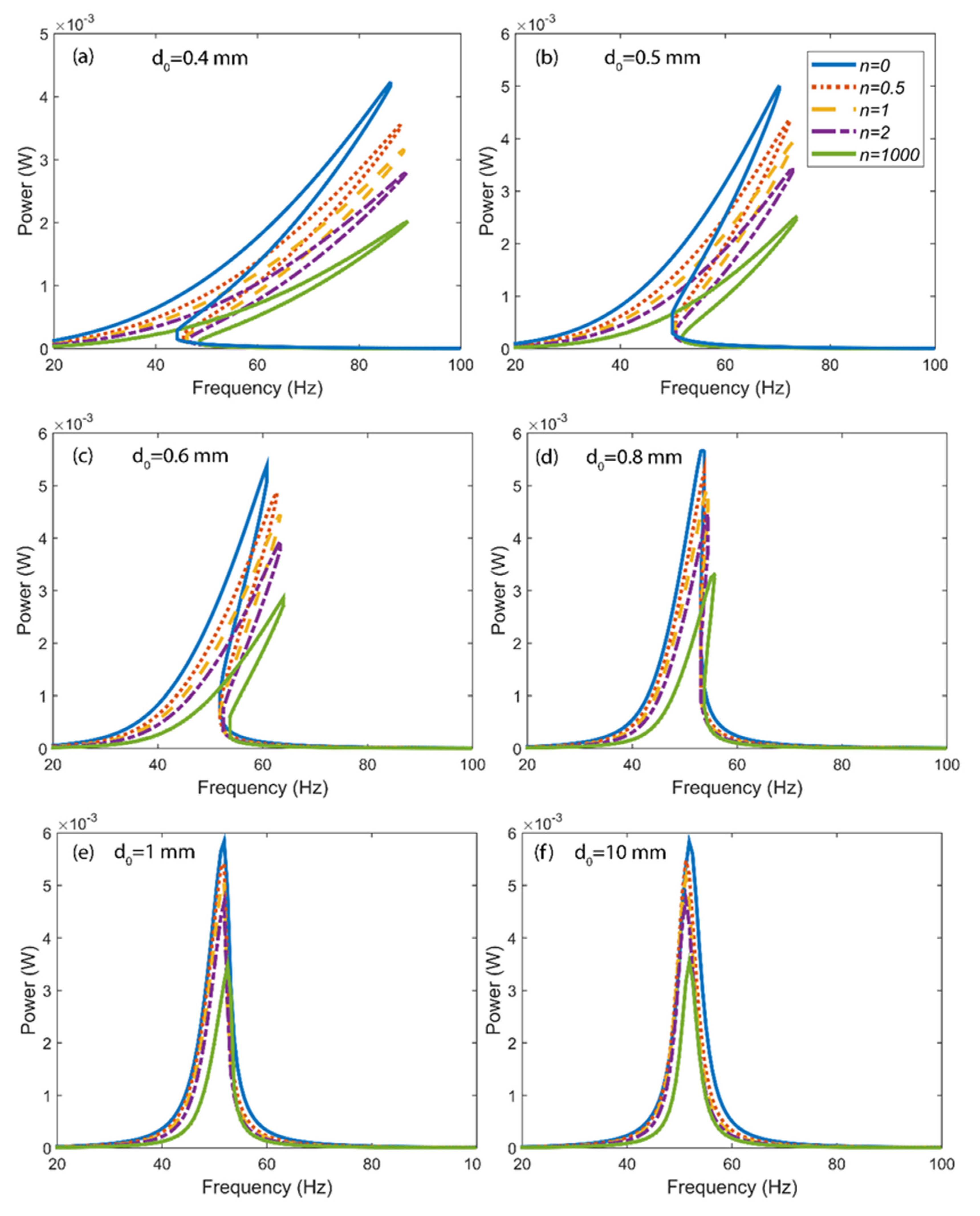
| 0.4 | 31.23 | 4.2 | 25.46 | 3.5 | 23.72 | 3.1 | 21.24 | 2.8 | 16.25 | 2.0 |
| 0.5 | 34.39 | 5.0 | 28.78 | 4.3 | 26 | 3.9 | 23.29 | 3.4 | 18.01 | 2.5 |
| 0.6 | 35.61 | 5.3 | 30.18 | 4.8 | 27.66 | 4.4 | 24.88 | 3.9 | 19.45 | 2.8 |
| 0.8 | 36.59 | 5.6 | 31.68 | 5.2 | 29.19 | 4.9 | 26.48 | 4.4 | 20.9 | 3.3 |
| 1 | 37.13 | 5.8 | 31.81 | 5.4 | 29.54 | 5.0 | 27.1 | 4.6 | 21.38 | 3.4 |
| 10 | 37.2 | 5.8 | 32.25 | 5.4 | 29.73 | 5.1 | 27.21 | 4.7 | 21.62 | 3.5 |
Publisher’s Note: MDPI stays neutral with regard to jurisdictional claims in published maps and institutional affiliations. |
© 2022 by the authors. Licensee MDPI, Basel, Switzerland. This article is an open access article distributed under the terms and conditions of the Creative Commons Attribution (CC BY) license (https://creativecommons.org/licenses/by/4.0/).
Share and Cite
Kumar, A.; Ansari, M.N.M.; Ibrahim, S.M.; Thomas, P.; Vaish, R. Functionally Graded Piezoelectric Energy Harvester: A Numerical Study. Electronics 2022, 11, 2595. https://doi.org/10.3390/electronics11162595
Kumar A, Ansari MNM, Ibrahim SM, Thomas P, Vaish R. Functionally Graded Piezoelectric Energy Harvester: A Numerical Study. Electronics. 2022; 11(16):2595. https://doi.org/10.3390/electronics11162595
Chicago/Turabian StyleKumar, Anuruddh, Mohamed Nainar Mohamed Ansari, Sobhy M. Ibrahim, Paramanandam Thomas, and Rahul Vaish. 2022. "Functionally Graded Piezoelectric Energy Harvester: A Numerical Study" Electronics 11, no. 16: 2595. https://doi.org/10.3390/electronics11162595
APA StyleKumar, A., Ansari, M. N. M., Ibrahim, S. M., Thomas, P., & Vaish, R. (2022). Functionally Graded Piezoelectric Energy Harvester: A Numerical Study. Electronics, 11(16), 2595. https://doi.org/10.3390/electronics11162595