Article

Supervisor Design for a Pressurized Reactor Unit in the Presence of Sensor and Actuator Faults

by
Fotis N. Koumboulis
1,*,
Dimitrios G. Fragkoulis
2,
Ioannis Kalkanas
2 and
George F. Fragulis
3
1
Department of Digital Industry Technologies, School of Science, National and Kapodistrian University of Athens, Euripus Campus, 157 72 Athens, Greece
2
Core Department, National and Kapodistrian University of Athens, Euripus Campus, 157 72 Athens, Greece
3
Laboratory of Robotics, Embedded and Integrated Systems, Department of Electrical and Computer Engineering, University of Western Macedonia, 501 00 Kozani, Greece
*
Author to whom correspondence should be addressed.
Electronics 2022, 11(16), 2534; https://doi.org/10.3390/electronics11162534
Submission received: 16 June 2022 / Revised: 4 August 2022 / Accepted: 11 August 2022 / Published: 13 August 2022
(This article belongs to the Section Systems & Control Engineering)

Abstract

:
The preservation of the efficient functionality of a pressurized reactor unit in the presence of faults is the aim of the present paper. To satisfy this aim, a distributed supervisory control scheme, considering the possibility of system faults, was designed. Towards this aim, the models of the subsystems of the total pressurized reactor unit in the presence of sensor and actuator faults are developed, using finite deterministic automata. This is the first contribution of the paper. The desired performance of the unit was formulated in the form of rules guaranteeing the desired behavior of a pressurize–depressurize cycle and safety specifications. The rules were translated to six desired regular languages. The realization of these languages, in the form of supervisor automata, was accomplished. This is the second contribution of the paper. A modular supervisory design scheme, towards safety and tolerance in the presence of faults, was proposed and realized, and the properties of the proposed supervisors and the controlled automaton were proven. This is the third contribution of the paper. The complexity of each supervisor was computed. The efficiency of the supervisory design scheme was illustrated through simulations. A PLC implementation of the derived supervisors was proposed. The derived supervisors are suitable for implementation as function blocks.

1. Introduction

Industrial processes have become more complex regarding their procedural behavior and the use of advanced equipment as well as environmental and safety restrictions. Many control methods have been developed regarding the operating procedures of such systems. Among them, there are methods aimed step-wise transitions between the operating points of the controlled process using artificial intelligence tools (indicatively, see [1]) and/or step-wise switching controllers (indicatively, see [2]) as well as discrete event system (DES) models and controllers (indicatively, see [3,4,5,6]). Most of these methods are implementable in low-level devices, such as programmable logic controllers (PLCs) and programmable automation controllers (PACs), providing logic and numerical processing features.
The use of DES and especially the Ramadge Wonham (RW) framework (see [7] and [8]) is offered for controller software development (see [9,10,11]), particularly in industrial applications. In the RW framework, the supervisory structure is capable to restrict some actions to the system and not to impose some actions (see [7,8]). According to [12,13,14], the RW framework provides sufficiently satisfactory results towards a system’s safety and deadlock avoidance. The design of supervisory control, taking into consideration the system’s faults, is a very important issue in industrial automation (see [15,16]). Furthermore, in modern industrial systems, the correlation of a system’s faults with cyberattacks has given the derivation of desired functionality specifications in the presence of faults additive value (see [17,18]).
In [3,4,6], the DES model of a pressurized reactor was developed and a supervisory control scheme, in the RW framework, was proposed. In the analysis presented in [3,4,6], the possibility of the presence of faults was not considered. Here, the problem of modeling and supervisor control of this pressurized reactor was studied in the presence of possible actuator and sensor faults. Appropriate models of the reactor unit subsystems in the presence of faults were developed. This is the first contribution of the present paper. The developed models were extensions of the respective models in [3,4,6]. In addition, appropriate desired performance rules, preserving the requirements for the desired pressurize–depressurize cycles proposed in [3,4,6], were imposed. The performance rules aimed to provide safety and tolerance in the presence of faults. The derivation of the rules and their expression as desired languages is the second contribution of the paper. Finally, in order to satisfy the desired performance rules, a modular supervisory control scheme was proposed, and the required properties of the scheme were proven. This is the third contribution of the paper. A PLC implementation of the supervisors was proposed. The complexity of the present supervisory scheme was computed and was shown to be low. It was mentioned that the derived supervisors were suitable for implementation as function blocks. The IEC 61499 standard, being an extension of IEC 61131-3, is based on using extended function blocks (see [19,20,21]). The implementation of supervisory control algorithms (see [20] and the references within), fault diagnosers (see [21] and the references within), and discrete event systems (see [20,22,23,24]) in IEC 61499 has already attracted considerable interest. The aim of the standard was to introduce the basic concepts for the control design of distributed industrial processes, providing robust and flexible software programs. The different function blocks create a network, sharing their inputs and outputs [22].
This paper is organized as follows: In Section 2, the notation and the notions used in the paper are presented. In Section 3, the models of the reactor unit subsystems in the presence of faults are presented in the form of six tuples. In Section 4, the design specifications are imposed and translated to the appropriate desired languages in analytic forms. In Section 5, the realization of the supervisory control scheme is accomplished in a modular architecture, and the satisfactory performance of the controlled automaton is proven. Finally, in Section 6, the implementation of the proposed supervisory control scheme for PLCs in ladder diagrams and general guidelines for implementation using function blocks are presented.

2. General Notation and Notions

The pressurized reactor unit was analyzed according to its subsystems. Here, each subsystem is modeled in the form of finite deterministic automata, described by six tuples in the form (see [25,26,27,28]) G = ( , E , f , , x 0 , m ) , where is the set of the states, E is the event set (alphabet), is the active event set function, f is the transition function, x 0 is the initial state, and m is the set of the marked states.
To demonstrate the structural properties of the reactor unit subsystems, the closed behavior [7], denoted by L ( G ) , and the marked behavior [7], denoted by L m ( G ) , are used. Clearly, it holds that L m ( G ) L ( G ) E , where E denotes the Kleene Star of E , see [7,8]. The set of the uncontrollable events of each subsystem is denoted by E u c E .
The finite deterministic automaton of a supervisor, denoted by S = ( S , E S , f S , S , x S , 0 , S , m ) , is used. The synchronous product [7] (or parallel composition [8]) of the automata S and G is denoted by S G . For the properties of the synchronous product of two or more automata, see [7,8]. For the supervisor to be physically realizable, through the synchronous product with G , the necessary and sufficient condition is the permissibility of the uncontrollable event transitions of G , via S G . For the supervisor to be efficient, it is necessary for the synchronous product S G to be a nonblocking automaton.
The complexity of the automaton of the supervisor is a significant characteristic of the design. The complexity of an automaton is the triad including the number of the states, the number of the events, and the number of the transitions of the automaton (indicatively, see [26,29]).

3. Modeling of the Pressurized Reactor Unit

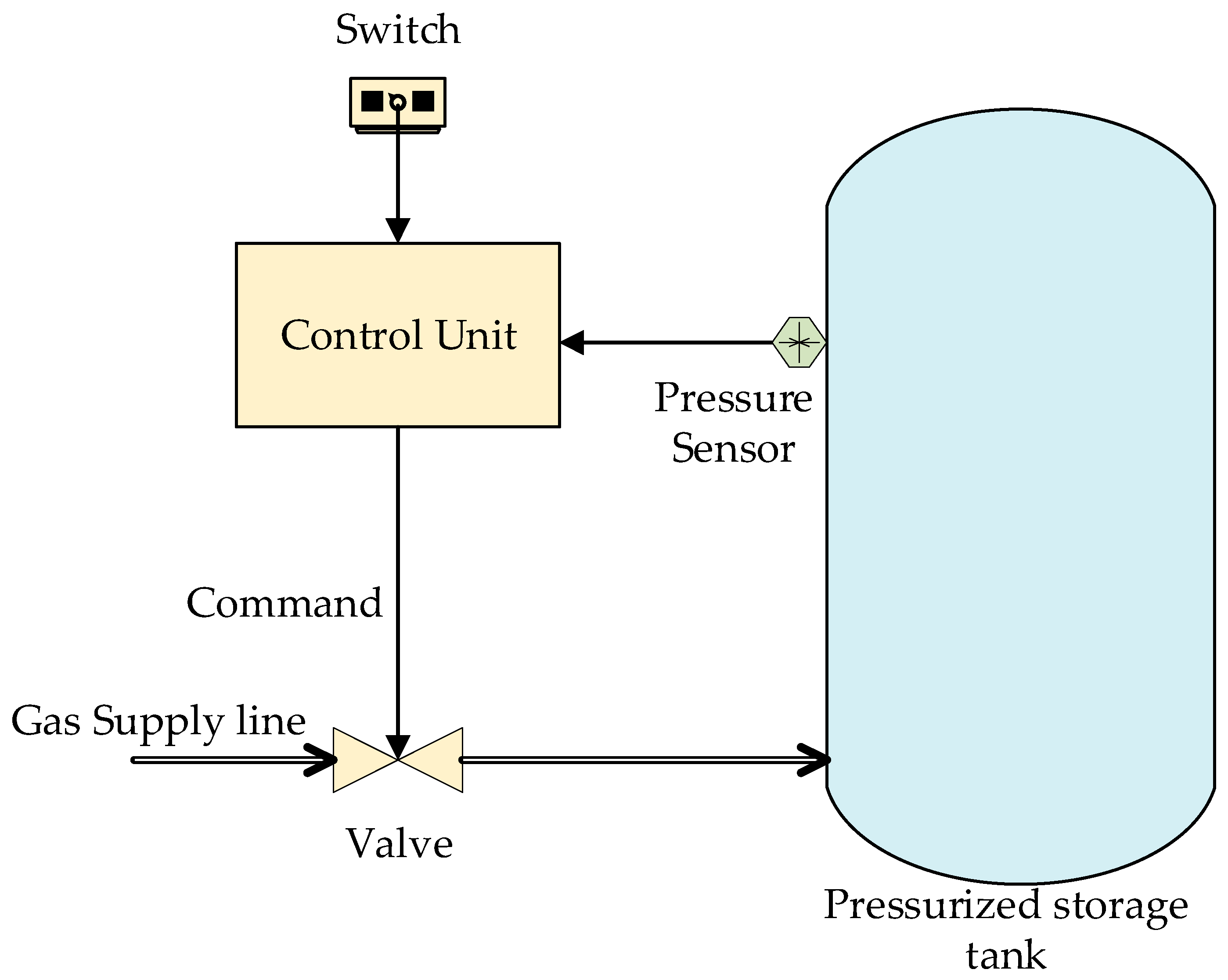
3.1. Description of the Unit

The main component of the system is a pressurized storage tank connected to a gas supply line. An on/off valve is the main control device charging the tank. Through a human–machine interface, the user sends commands to open or close the valve. The human–machine interface is usually an HMI monitor or a common two state switch (button). A pressure sensor is installed in the tank providing information regarding the pressure lever, namely, “low”, “medium”, or “high”. It is important to mention that the desired pressure level of the tank is “medium”. In accordance with [4], a schematic of the interconnection among the subsystems of the reactor unit is presented in Figure 1. The reactor unit was modeled in [3,4,6] via finite deterministic automata for the case where the presence of faults was not included.

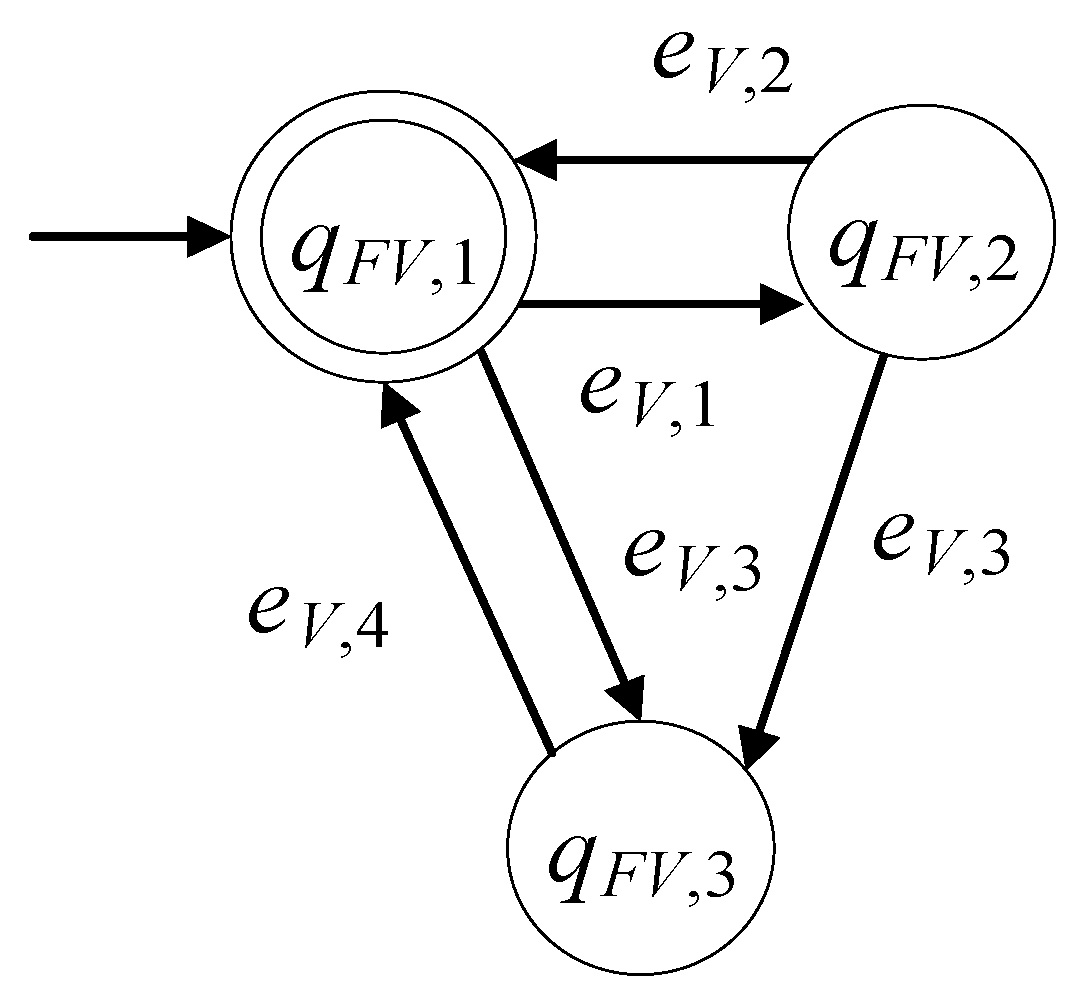
3.2. The Model of the Valve including Faults

Using the valve model for the nonfaulty case (see [3,4,6]), the respective model in the presence of faults is developed to be G F V = ( F V , E F V , f F V , F V , x F V , 0 , F V , m ) . The set of the states is F V = { q F V , 1 , q F V , 2 , q F V , 3 } . The state q F V , 1 is the case where the valve is closed. The state q F V , 2 is the case where the valve is open. The state q F V , 3 is the case where the valve is in the faulty mode. The initial state of G F V is x F V , 0 = q F V , 1 . The set of the marked states is V , m = { q V , 1 } . The alphabet of G F V is E F V = { e V , 1 , e V , 2 , e V , 3 , e V , 4 } . The event e V , 1 commands the valve to open. The event e V , 2 commands the valve to close. The event e V , 3 indicates that a fault took place at the valve. The event e V , 4 indicates that the fault was repaired. The set of the controllable events is E F V , c = { e V , 1 , e V , 2 } , and the set of the uncontrollable events is E F V , u c = { e V , 3 , e V , 4 } .
The sets of the active events, per state of G F V , are:
F V ( q F V , 1 ) = { e V , 1 , e V , 3 } , F V ( q F V , 2 ) = { e V , 2 , e V , 3 } , F V ( q F V , 3 ) = { e V , 4 } .
The transitions, per state and event of G F V , are:
f F V ( q F V , 1 , e V , 1 ) = q F V , 2 , f F V ( q F V , 1 , e V , 3 ) = q F V , 3 , f F V ( q F V , 2 , e V , 2 ) = q F V , 1 , f F V ( q F V , 2 , e V , 3 ) = q F V , 3 ,
f F V ( q F V , 3 , e V , 4 ) = q F V , 1 .
The closed behavior of the automaton of the valve is:
L ( G F V ) = ( ( e V , 3 e V , 4 ) * e V , 1 ( e V , 2 + e V , 3 e V , 4 ) ) * ¯ .
The marked behavior of the automaton of the valve is:
L m ( G F V ) = ( ( e V , 3 e V , 4 ) * e V , 1 ( e V , 2 + e V , 3 e V , 4 ) ) * .
Clearly, L m ( G F V ) ¯ = L ( G F V ) . Thus, G F V is a nonblocking automaton. For the nonblocking property of an automaton, see [7,8].
In Figure 2, the state diagram of the automaton of the valve is presented. If the fault event, the fault repair event, and the state describing the faulty mode are neglected, then the state diagram is reduced to that in [3,4,6].

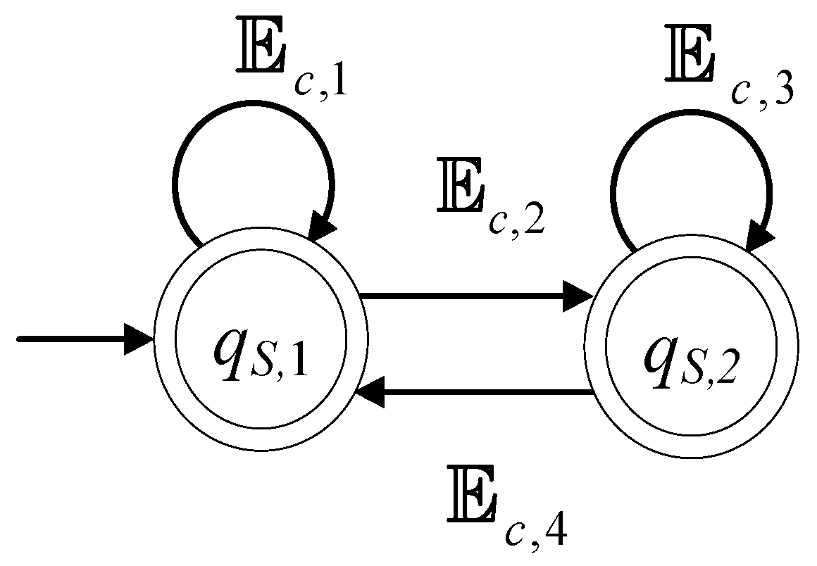
3.3. The Model of the Switch in the Presence of Faults

The model of the switch (button) in the presence of faults is expressed in the form G F B = ( F B , E F B , f F B , F B , x F B , 0 , F B , m ) . The set of the states is F B = { q F B , 1 , q F B , 2 , q F B , 3 } . The state q F B , 1 is the case where the switch is turned off. The state q F B , 2 is the case where the switch is turned on. The state q F B , 3 is the case where the switch is in the faulty mode. The initial state is x F B , 0 = q F B , 1 . The set of the marked states is F B , m = { q F B , 1 } . The alphabet is E F B = { e B , 1 , e B , 2 , e B , 3 , e B , 4 } . The event e B , 1 indicates that the switch is turned on. The event e B , 2 indicates that the switch is turned off. The event e B , 3 indicates that a fault took place. The event e B , 4 indicates that the fault was repaired. The set of the controllable events is E F B , c = , and the set of the uncontrollable events is E F B , u c = E F B .
The sets of the active events, per state of G F B , are:
F B ( q F B , 1 ) = { e B , 1 , e B , 3 } ,
F B ( q F B , 2 ) = { e B , 2 , e B , 3 } ,
F B ( q F B , 3 ) = { e B , 4 } .
The transitions, per state and event of G F B , is:
f F B ( q F B , 1 , e B , 1 ) = q F B , 2 ,
f F B ( q F B , 1 , e B , 3 ) = q F B , 3 ,
f F B ( q F B , 2 , e B , 2 ) = q F B , 1 ,
f F B ( q F B , 2 , e B , 3 ) = q F B , 3 ,
f F B ( q F B , 3 , e B , 4 ) = q F B , 1 .
The closed behavior of the automaton of the switch is:
L ( G F B ) = ( ( e B , 3 e B , 4 ) * e B , 1 ( e B , 2 + e B , 3 e B , 4 ) ) * ¯ .
The marked behavior of the automaton of the switch is:
L m ( G F B ) = ( ( e B , 3 e B , 4 ) * e B , 1 ( e B , 2 + e B , 3 e B , 4 ) ) * .
G F B is a nonblocking automaton, i.e., L m ( G F V ) ¯ = L ( G F V ) .
In Figure 3, the state diagram of the automaton of the switch is presented. In the nonfaulty case, the diagram is reduced to the respective state diagrams in [3,4,6].

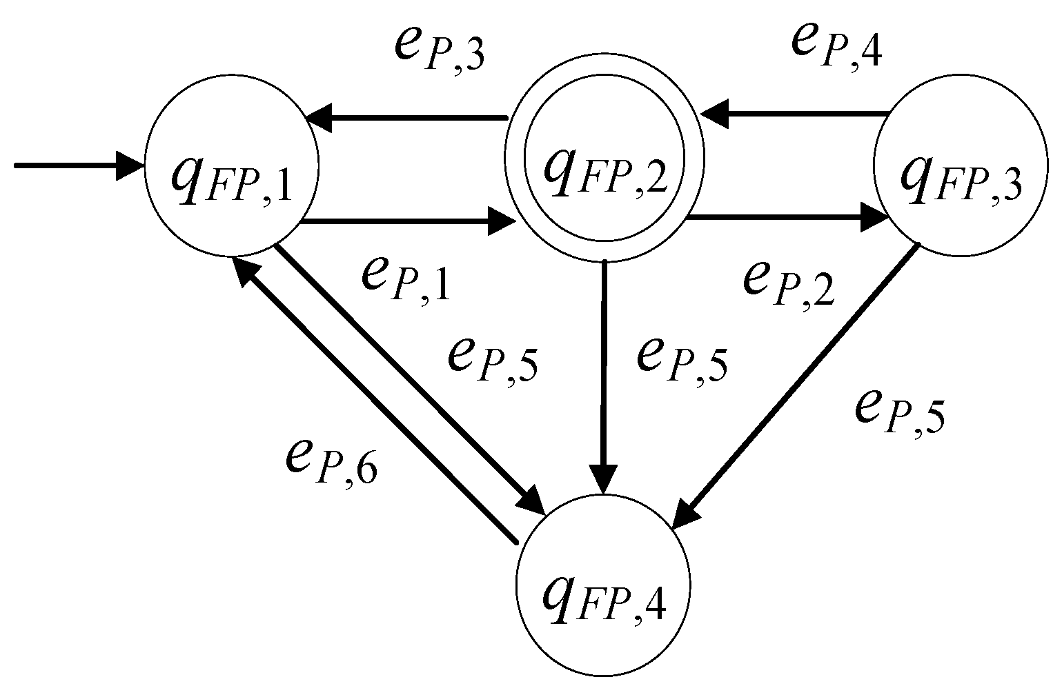
3.4. The Model of the Pressure Sensor in the Presence of Faults

The model of the pressure sensor in the presence of faults is in the form G F P = ( F P , E F P , f F P , F P , x F P , 0 , F P , m ) . The set of the states is F P = { q F P , 1 , q F P , 2 , q F P , 3 , q F P , 4 } . The state q F P , 1 is the case where the pressure sensor shows low pressure. The state q F P , 2 is the case where the pressure sensor shows medium pressure, which is the desired pressure. The state q F P , 3 is the case where the pressure sensor shows high pressure. The state q F P , 4 is the case where the sensor is in the faulty mode. The initial state is x F P , 0 = q F P , 1 . The set of the marked states is F P , m = { q F P , 2 } . The alphabet is E F P = { e P , 1 , e P , 2 , e P , 3 , e P , 4 , e P , 5 , e P , 6 } . The events e P , 1 and e P , 2 indicate that the pressure has risen from low to medium and from medium to high, respectively. The events e P , 3 and e P , 4 indicate that the pressure has dropped from medium to low and from low to medium, respectively. The event e P , 5 indicates that a pressure sensor fault took place. The event e P , 6 indicates that the fault was repaired. The controllable events set is E F P , c = , and the uncontrollable events set is E F P , u c = E F P .
The set of the active events, per state of G F P , is:
F P ( q F P , 1 ) = { e P , 1 , e P , 5 } ,
F P ( q F P , 2 ) = { e P , 2 , e P , 3 , e P , 5 } ,
F P ( q F P , 3 ) = { e P , 4 , e P , 5 } ,
F P ( q F P , 4 ) = { e P , 6 } .
The transitions, per state and event of G F P , are:
f F P ( q F P , 1 , e P , 1 ) = q F P , 2 ,
f F P ( q F P , 1 , e P , 5 ) = q F P , 4 ,
f F P ( q F P , 2 , e P , 2 ) = q F P , 3 ,
f F P ( q F P , 2 , e P , 5 ) = q F P , 4 ,
f F P ( q F P , 2 , e P , 3 ) = q F P , 1 ,
f F P ( q F P , 3 , e P , 4 ) = q F P , 2 ,
f F P ( q F P , 3 , e P , 5 ) = q F P , 4 ,
f F P ( q F P , 4 , e P , 6 ) = q F P , 1 .
The closed behavior of G F P is:
L ( G F P ) = ( ( e P , 5 e P , 6 ) * e P , 1 ( ( e P , 2 e P , 4 ) * ( ( ε + e P , 2 ) e P , 5 e P , 6 + e P , 3 ) ) ) * _ _ _ _ _ _ _ _ _ _ _ _ _ _ _ _ _ _ _ _ _ _ _ _ _ _ _ _ _ _ _ _ _ _ _ _ _ _ _ _ _ _ _ _ _ _ _ _ _ _ _ _ _ _ _ _ _ _ _ _ _ _ _ _ _ _ _   .
The marked behavior of G F P is:
L m ( G F P ) = ( e P , 5 e P , 6 ) * e P , 1 ( ( e P , 2 e P , 4 ) * ( ( ε + e P , 2 ) e P , 5 e P , 6 + e P , 3 ) ( e P , 5 e P , 6 ) * e P , 1 ) *   .
Clearly, G F P is a nonblocking automaton, i.e., L m ( G F P ) ¯ = L ( G F P ) .
In Figure 4, the state diagram of the automaton of the sensor pressure is presented. In the nonfaulty case, the diagram is reduced to those in [3,4,6].

3.5. The Total Automaton

It is observed that the alphabets of the automata of the three subsystems presented in Section 3.2, Section 3.3 and Section 3.4 are disjoint sets. Hence, the synchronous product of the three automata, i.e., G F = G F V G F B G F P , is shuffle [8]. The automaton G F is the model of the total reactor unit.
The set of the states of G F is F = F V × F B × F P and the states are of the form q F = ( q F V , q F B , q F P ) . The alphabet of the automaton is E F = E F V E F B E F P . Clearly, all transitions of the three automata, in Section 3.2, Section 3.3 and Section 3.4, are feasible. The active events sets of G F have the property F ( ( q F V , q F B , q F P ) ) = F V ( q F V ) F B ( q F B ) F P ( q F P ) . The set of the marked states is F , m = { ( q F V , 1 , q F B , 1 , q F P , 1 ) } .
Here, the events indicating faults and the events indicating repairs are available to the controller platform via appropriate sensors. This is an expected characteristic in modern manufacturing practice. Therefore, in what follows, these events will be considered to be observable.
In Table 1, the simulation of G F is presented for a predefined event sequence. Details regarding simulation of discrete event systems can be found in Chapter 10 of Reference [8]. It is important to mention that the results of the simulation have also been verified using the discrete event systems simulation software “Supremica” [23]. According to line 5 of Table 1, the event e P , 2 took place. Thus, the pressure in the reactor was high. According to line 6 of Table 1, the valve closed (event e V , 2 ), allowing the pressure to drop to the desired value. Nevertheless, according to line 7 of the table, the event e V , 1 took place. The event opened the valve once again. The pressure had not yet dropped significantly, i.e., the pressure of the reactor was still high. Thus, the pressure of the reactor can be further increased with a plausible negative impact on the reactor’s functionality and safety. According to line 12 of the table, an event indicating the appearance of a pressure sensor fault took place (i.e., event e P , 5 ). According to line 14 of the table, the command to open the valve took place once again, while the pressure sensor was in the faulty mode; therefore, there was no available information regarding the value of the pressure of the reactor. Hence, opening the valve without knowledge of the reactor’s pressure may further aggravate the aforementioned problems regarding the system’s safety and functionality.

4. Desired Behavior

In ([3,4,6]), the desired behavior of the system focuses on the pressurize–depressurize cycle of the reactor without considering the presence of eventual faults. According to [3,4,6], the desired pressurize–depressurize cycle is: first, the user turns on the switch; next, the valve opens; after, when the pressure is at medium, then the valve closes (the switch can only be turned off); then, if the pressure level becomes low, the valve opens (the switch can only be turned on). In addition to the sequence of the cycle and according to [3,4,6], the following two rules are imposed: (1) if the pressure is beyond its desired level (i.e., medium), then the command to close the valve is disactivated regardless of the switch command; (2) if the pressure is higher than its desired level (i.e., medium), then the command to open the valve is disactivated regardless of the switch command.
Here, the above reported desired pressurize–depressurize cycle and the two rules were preserved and the desired specifications were enriched with requirements considering the possibility of the presence of the faults. Hence, all the desired specifications were formulated as follows:
  • When a fault takes place in the total system of the reactor unit, then the command to open the valve is disactivated until the fault repair;
  • If the pressure in the reactor is lower than its desired level, then the command to close the valve is disactivated, regardless of the switch command;
  • If the pressure in the reactor is higher than its desired level, then the command to open the valve is disactivated, regardless of the switch command;
  • The pressurize–depressurize cycle is preserved.
The 1st rule can be analyzed into the following three prefixed closed, regular languages:
K 1 1 = ( ( e V , 1 + e V , 2 + e V , 4 ) * e V , 3 ( e V , 2 + e V , 3 ) * e V , 4 ) * ¯ ,
K 1 2 = ( ( e V , 1 + e V , 2 + e V , 3 + e B , 4 ) * e B , 3 ( e V , 2 + e V , 3 ) * e B , 4 ) * ¯ ,
K 1 3 = ( ( e V , 1 + e V , 2 + e V , 3 + e P , 6 ) * e P , 5 ( e V , 2 + e V , 3 ) * e P , 6 ) * ¯ .
The 2nd rule is expressed by the prefixed closed language:
K 2 = ( ( e P , 3 + e P , 6 ) * e P , 1 ( e P , 1 + e V , 2 ) * ( e P , 3 + e P , 6 ) ) * ¯ .
The 3rd rule is expressed by the prefixed closed language:
K 3 = ( ( e V , 1 + e P , 4 + e P , 6 ) * e P , 2 e P , 2 * ( e P , 4 + e P , 6 ) ) * ¯ .
The 4th rule is expressed by the prefixed closed language K 4 = K 0 4 _ _ _ _ , where:
K 0 4 = ( ( e B , 2 + e P , 1 + e P , 3 ) * e B , 1 ( e B , 1 + e B , 2 + e P , 1 + e P , 3 ) * e V , 1 ( e B , 1 + e B , 2 + e P , 3 ) *          e P , 1 ( e B , 1 + e B , 2 + e P , 1 + e P , 3 ) * e V , 2 ( e B , 1 + e P , 1 + e P , 3 ) * e B , 2 ( e B , 1 + e B , 2 + e P , 1 ) * e P , 3 ) * .
The following alphabets:
E 1 S , 1 = { e V , 1 , e V , 2 , e V , 3 , e V , 4 } ,
E 1 S , 2 = { e V , 1 , e V , 2 , e V , 3 , e B , 3 , e B , 4 } ,
E 1 S , 3 = { e V , 1 , e V , 2 , e V , 3 , e P , 5 , e P , 6 } ,
E 2 S = { e V , 2 , e P , 1 , e P , 3 , e P , 6 } ,
E 3 S = { e V , 1 , e P , 2 , e P , 4 , e P , 6 } ,
E 4 S = { e V , 1 , e V , 2 , e B , 1 , e B , 2 , e P , 1 , e P , 3 } .
are the alphabets of K 1 1 , K 1 2 , K 1 3 , K 2 , K 3 , and K 4 , respectively.
To satisfy the specifications 1–4, G F must be appropriately controlled. The desired performance of the controlled automaton is described by the following six languages, where the first three correspond to the 1st rule, and the remaining three correspond to the 2nd, the 3rd, and the 4th rule, respectively
K 1 D , k = P 1 k 1 ( K 1 k ¯ ) L m ( G F ) ,   k = 1 , 2 , 3
K D = P 1 ( K ¯ ) L m ( G F ) ,   = 2 , 3 , 4
In (1), the functions P 1 1 , P 1 2 , and P 1 3 denote the projections E F to E 1 S , 1 , E 1 S , 2 , and E 1 S , 3 , respectively. In (2), the functions P 2 , P 3 , and P 4 denote the projections of E F to E 2 S , E 3 S , and E 4 S , respectively. The definition and the properties of the projections can be found in [7,8].

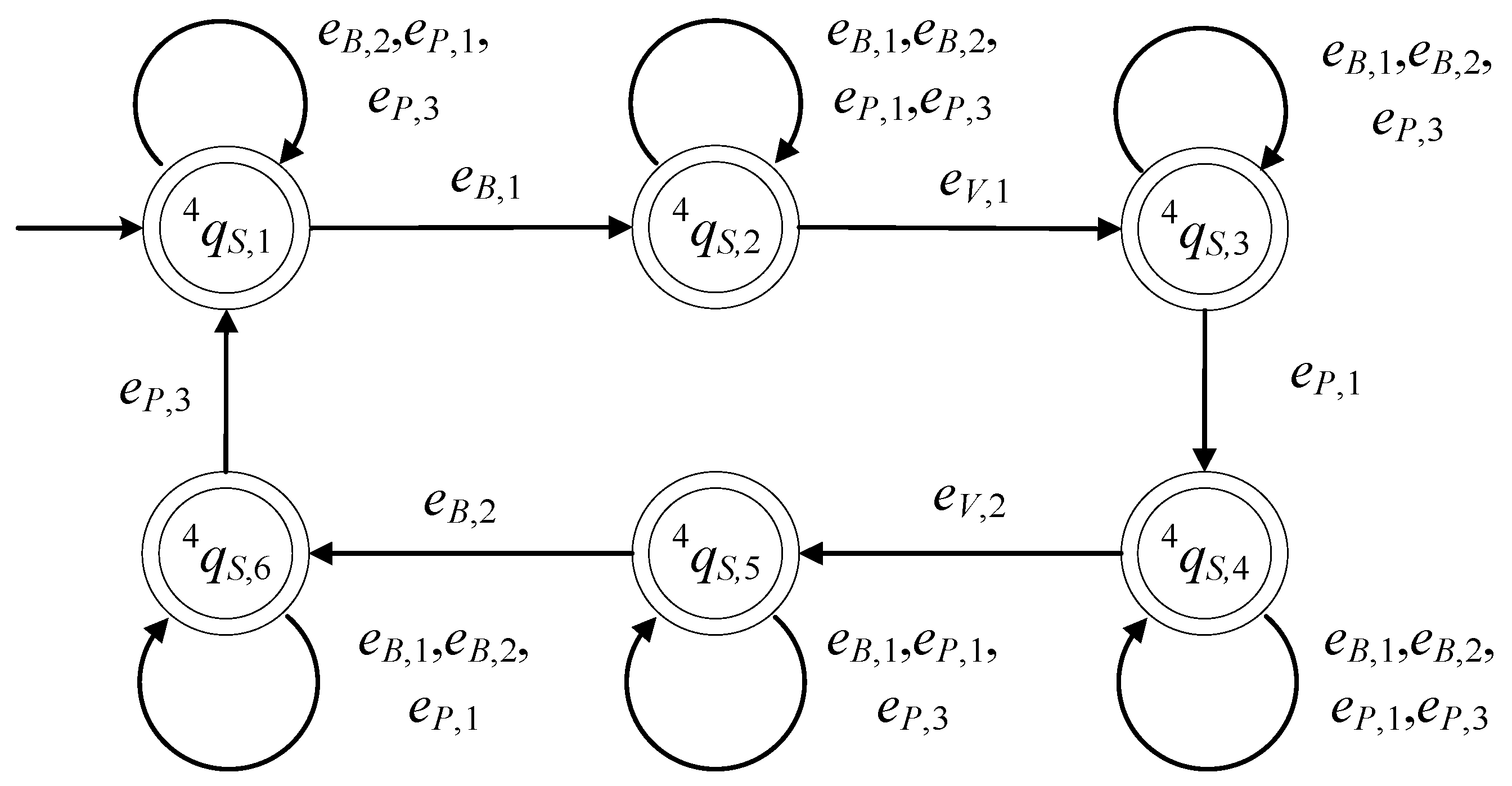
5. Supervisory Control Design

5.1. Realization of Supervisors

Consider the class of supervisor automata [7,8], denoted by S = ( S , E S , f S , S , x S , 0 , S , m ) , where S = { q S , 1 , q S , 2 } is the set of its states. This class is parameterized by four regular languages, expressed by the four regular expressions c 1 , c 2 , c 3 , and c 4 . Let E c , 1 , E c , 2 , E c , 3 , and E c , 4 be the alphabets of the expressions c 1 , c 2 , c 3 , and c 4 , respectively. The alphabet of the supervisor automaton is E S = E c , 1 E c , 2 E c , 3 E c , 4 . Its initial state is denoted by x S , 0 = q S , 1 . For the set of the marked states, it holds that S , m = S , i.e., all states are marked. The active event sets, per state, are defined to be S ( q S , 1 ) = E c , 1 E c , 2 and S ( q S , 2 ) = E c , 3 E c , 4 . The transitions of S , per state and event, are defined to be:
f S ( q S , 1 , e ) = q S , 1 ,    e E c , 1 ,
f S ( q S , 1 , e ) = q S , 2 ,    e E c , 2 ,
f S ( q S , 2 , e ) = q S , 2 ,    e E c , 3 ,
f S ( q S , 2 , e ) = q S , 1 ,    e E c , 4 ,
The complexity triad of S is ( 2 ,   E S , E S ) . Its state diagram is presented in Figure 5. Based on the automaton S , the supervisors of the desired regular languages, given in definitions (1) and (2), are realized.
The supervisor realizing the prefix closed language K 1 1 is denoted by S 1 1 , and it is derived from S by letting c 1 = e V , 1 + e V , 2 + e V , 4 , c 2 = e V , 3 , c 3 = e V , 2 + e V , 3 , and c 4 = e V , 4 . The complexity triad of S 1 1 is ( 2 ,   4 ,   7 ) . The supervisor realizing the prefix closed language K 1 2 is denoted by S 1 2 , and it is derived from S by letting c 1 = e V , 1 + e V , 2 + e V , 3 + e B , 4 , c 2 = e B , 3 , c 3 = e V , 2 + e B , 3 , and c 4 = e B , 4 . The complexity triad is ( 2 ,   4 ,   8 ) . The supervisor realizing the prefix closed language K 1 3 is denoted by S 1 3 and it is derived from S by letting c 1 = e V , 1 + e V , 2 + e V , 3 + e P , 6 , c 2 = e P , 5 , c 3 = e V , 2 + e P , 5 , and c 4 = e P , 6 . The complexity triad of S 1 3 is also ( 2 ,   4 ,   8 ) . The supervisor realizing the prefix closed language K 2 is denoted by S 2 , and it is derived from S by letting c 1 = e P , 3 + e P , 6 , c 2 = e P , 1 , c 3 = e P , 1 + e V , 2 , and c 4 = e P , 3 + e P , 6 . The respective complexity triad is ( 2 ,   4 ,   7 ) . The supervisor realizing the prefix closed language K 3 is denoted by S 3 and it is derived from S by letting c 1 = e V , 1 + e P , 4 + e P , 6 , c 2 = e P , 2 , c 3 = e P , 2 , and c 4 = e P , 4 + e P , 6 . The respective complexity triad is ( 2 ,   4 ,   7 ) .
The supervisor realizing the prefix closed language K 4 is S 4 = ( 4 S , E 4 S , f 4 S , 4 S , x 4 S , 0 , 4 S , m ) . The set of the states of S 4 is 4 S = λ = 1 6 { q 4 S , λ } . The alphabet of S 4 is E 4 S . The initial state is x 4 S , 0 = q 4 S , 1 , and the set of the marked states is 4 S , m = 4 S . The active event sets, per state of S 4 , are:
4 S ( q 4 S , 1 ) = { e B , 1 , e B , 2 , e P , 1 , e P , 3 } ,
4 S ( q 4 S , 2 ) = { e V , 1 , e B , 1 , e B , 2 , e P , 1 , e P , 3 } ,
4 S ( q 4 S , 3 ) = 4 S ( q 4 S , 5 ) = 4 S ( q 4 S , 6 ) = 4 S ( q 4 S , 1 ) ,
4 S ( q 4 S , 4 ) = { e V , 2 , e B , 1 , e B , 2 , e P , 1 , e P , 3 } .
The transitions of the supervisor, per state and event, are:
f 4 S ( q 4 S , 1 , e B , 1 ) = q 4 S , 2 ,
f 4 S ( q 4 S , 1 , e B , 2 ) = q 4 S , 1 ,
f 4 S ( q 4 S , 1 , e P , 1 ) = q 4 S , 1 ,
f 4 S ( q 4 S , 1 , e P , 3 ) = q 4 S , 1 ,
f 4 S ( q 4 S , 2 , e V , 1 ) = q 4 S , 3 ,
f 4 S ( q 4 S , 2 , e B , 1 ) = q 4 S , 2 ,
f 4 S ( q 4 S , 2 , e B , 2 ) = q 4 S , 2 ,
f 4 S ( q 4 S , 2 , e P , 1 ) = q 4 S , 2 ,
f 4 S ( q S , 2 , e P , 3 ) = q 4 S , 2 ,
f 4 S ( q 4 S , 3 , e P , 1 ) = q 4 S , 4 ,
f 4 S ( q 4 S , 2 , e B , 2 ) = q 4 S , 2 ,
f 4 S ( q 4 S , 3 , e B , 2 ) = q 4 S , 3 ,
f 4 S ( q 4 S , 3 , e P , 3 ) = q 4 S , 3 ,
f 4 S ( q 4 S , 4 , e V , 2 ) = q 4 S , 5 ,
f 4 S ( q 4 S , 4 , e B , 1 ) = q 4 S , 4 ,
f 4 S ( q 4 S , 4 , e B , 2 ) = q 4 S , 4 ,
f 4 S ( q 4 S , 4 , e P , 1 ) = q 4 S , 4 ,
f 4 S ( q 4 S , 4 , e P , 3 ) = q 4 S , 4 ,
f 4 S ( q 4 S , 5 , e B , 2 ) = q 4 S , 6 ,
f 4 S ( q 4 S , 5 , e B , 1 ) = q 4 S , 5 ,
f 4 S ( q 4 S , 5 , e P , 1 ) = q 4 S , 5 ,
f 4 S ( q 4 S , 5 , e P , 3 ) = q 4 S , 5 ,
f 4 S ( q 4 S , 6 , e P , 3 ) = q 4 S , 1 ,
f 4 S ( q 4 S , 6 , e B , 1 ) = q 4 S , 6 ,
f 4 S ( q 4 S , 6 , e B , 2 ) = q 4 S , 6 ,
f 4 S ( q 4 S , 6 , e P , 1 ) = q 4 S , 6 .
The complexity triad of S 4 is ( 6 ,   6 ,   26 ) . Its state diagram is presented in Figure 6.

5.2. The Performance of the Controlled System

In order to achieve the desired performance presented in Section 4, using the supervisors introduced in Section 5.1, the controlled automaton is proposed to be the synchronous product of the six supervisors and the total automaton of G F :
G F , c = S 1 1 S 1 2 S 1 3 S 2 S 3 S 4 G F .
From (3), it can be observed that the closed and the marked behavior of the controlled automaton are:
L ( G F , c ) = L ( G F ) P 1 1 1 ( K 1 1 ¯ ) P 1 2 1 ( K 1 2 ¯ ) P 1 3 1 ( K 1 3 ¯ ) P 2 1 ( K 2 ¯ ) P 3 1 ( K 3 ¯ ) P 4 1 ( K 4 ¯ ) .
Using (1) and (2), it holds that:
L m ( G F , c ) = K 1 D , 1 K 2 D , 1 K 3 D , 1 K 1 D , 2 K 2 D , 2 K 3 D , 2 K 1 D , 3 K 2 D , 3 K 1 D , 4 K 2 D , 4 .
The application of the six supervisors to the automaton G F , through the synchronous product in (3), is physically realizable if and only if the transitions of the process G F , activated by the uncontrollable events of G F , are not obstructed by the six supervisors. Clearly, the transitions from the states of G F , being nonaccessible in the synchronous product (3), were not tested. This physical realizability property is clearly equivalent to the controllability (see [8], p. 147) of the prefixed closed languages K 1 1 , K 1 2 , K 1 3 , K 2 , K 3 , and K 4 with regard to G F . To this end, the following proposition are established.
Proposition 1.
The prefixed closed languages K 1 1 , K 1 2 , K 1 3 , K 2 , K 3 , and K 4 are controllable regarding G F .
Proof. 
Here, physical realizability is tested. First, it can be observed that the uncontrollable events of G F , not belonging to the alphabet of a supervisor, are not obstructed in producing transitions. Second, the rest of the uncontrollable events (i.e., the uncontrollable events of the supervisors) are examined one by one. The uncontrollable events of S 1 1 , namely, the uncontrollable events of K 1 1 , are the events e V , 3 and e V , 4 . These events are active events of every state of S 1 1 . Thus, it was concluded that for every q 1 S , 1 , being a state of S 1 1 , and every q F F , it holds that:
If e V , 3 F ( q F ) , then e V , 3 ( 1 S , 1 ( q 1 S , 1 ) F ( q F ) ) .
If e V , 4 F ( q F ) , then e V , 4 ( 1 S , 1 ( q 1 S , 1 ) F ( q F ) ) .
Hence, in the synchronous product S 1 1 G F , the supervisor S 1 1 does not obstruct the transitions of G F being activated by the uncontrollable events e V , 3 and e V , 4 . Thus, the controllability of K 1 1 , regarding G F , is proven. This proof can directly be extended to cover the controllability of K 1 2 by focusing on the uncontrollable events e B , 3 and e B , 4 . Following the same procedure, the controllability of the languages K 1 3 , K 2 , K 3 , and K 4 is also proven by focusing on:
-
The uncontrollable events e P , 3 and e P , 4 for K 1 3 ;
-
The uncontrollable events e P , 1 , e P , 3 , and e P , 6 for K 2 ;
-
The uncontrollable events e P , 2 , e P , 4 and e P , 6 for K 2 ;
-
The uncontrollable events e B , 1 , e B , 2 , e P , 1 , and e P , 3 for K 4 .
According to (5), the performance of the controlled automaton G F , c , regarding its marked behavior, is satisfactory. The closed behavior of G F , c is satisfactory if and only if G F , c is nonblocking, i.e., L m ( G F , c ) ¯ = L ( G F , c ) . This property will be proven in Proposition 2.
Proposition 2.
The controlled automaton G F , c is a nonblocking automaton.
Proof. 
According to Figure 5 and Figure 6, all states of all supervisors are marked states. Thus, in order to investigate nonblocking of the controlled automaton G F , c , it suffices to check if there always exist active events in G F that are not obstructed by the supervisors to trigger at least one transmission from every nonmarked state to a marked state. Since G F is the shuffle of its subsystems, the latter goal is reduced to the existence of appropriate active events in every subsystem that are not obstructed by the supervisors to trigger at least one transmission from every nonmarked state to a marked state. To investigate the problem, it is remarked that, according to Proposition 1, the transmissions triggered by uncontrollable events are not obstructed by the supervisors. Using this remark, it is observed that the events indicating faults and the events indicating fault repairs, being uncontrollable events, are not obstructed to activate transitions of the controlled automaton G F , c to marked states. Hence, in what follows only the nonmarked states, being “nonfaulty” in the subsystems G F B , G F P , and G F V , are examined. Regarding G F B and G F P , it will be proved that the “nonfaulty” and nonmarked states of the synchronous product of the automata G F B , G F P and the respective supervisors have always an uncontrollable event in their active events sets, triggering a transition to a marked state.Particularly, for the subsystem G F B , it holds that the uncontrollable event e B , 2 , being active in the “nonfaulty” and nonmarked state, activates the transition to the marked state (see Figure 3). For the subsystem G F P and according to Figure 4, it is observed that each of the uncontrollable events, e P , 1 and e P , 4 , participates in the active event set of one of the two “nonfaulty” and nonmarked states and activates the transition to the marked state of G F P . For the subsystem G F V and according to Figure 2, the transition from the nonmarked state q F V , 2 , not being a “faulty mode” state to the marked state q F V , 1 is accomplished through the controllable event e V , 2 . It is observed that e V , 2 belongs to the active event sets of all states of the supervisors S 1 1 , S 1 2 , and S 1 3 . Regarding S 3 , it is observed that e V , 2 does not belong to its alphabet. Thus, e V , 2 is not obstructed to activate the transition from q F V , 2 to the marked state q F V , 1 . Regarding S 2 , it is observed that e V , 1 does not belong to the alphabet. Thus, the transition from the marked state q F V , 1 to the unmarked state q F V , 2 is always permissible. If the automaton G F V is at q F V , 2 then S 2 , is at its 1st or its 2nd state. If it is at the 1st state then the uncontrollable event e P , 1 activates the transition to the 2nd, where e V , 2 is an active event, thus allowing the transition from q F V , 2 to q F V , 1 . Regarding S 4 , it is observed that for G F V to be at q F V , 2 , the automaton S 4 must be at q 4 S , 3 or at q 4 S , 4 . The transition from q 4 S , 3 to q 4 S , 4 can be accomplished through the uncontrollable event e P , 1 . Clearly, e V , 2 is an active event of q 4 S , 4 . Thus, the event sequence e P , 1 e V , 2 leads S 4 to the state q 4 S , 5 and G F V to the marked state q F V , 1 . □
From the proof of Proposition 2, the following corollary being of significant practical importance is derived.
Corollary 1.
The nonblocking property of G F , c is sufficiently strong in the sense that its marked states are always accessible from its initial state, through words that do not necessarily include events indicating faults or fault repairs.
In Table 2, the simulation of the controlled automaton G F , c is presented for the same predefined event sequence used for the simulation of G F (see Table 1). The results of the present simulation have also been verified using the discrete event systems simulation software “Supremica”. According to line 5 of Table 2, the event e P , 2 takes place. This means that the pressure in the reactor is high. According to line 6 of the table, the valve closes (event e V , 2 ) and allows the pressure to drop to the desired value. According to line 7 of the table, the event e V , 1 takes place (i.e., the command to open the valve). The controllable event e V , 1 is disabled by the supervisor S 1 3 to trigger transitions. Thus, the valve of the system remains closed. According to line 12 of the table, the event indicating the appearance of a pressure sensor fault takes place (i.e., event e P , 5 ). According to line 14 of the table, the command to open the valve takes place once again, while the pressure sensor is in the faulty mode. The controllable event e V , 1 is disabled by the supervisor S 3 to trigger transitions. Thus, the valve of the system stays closed.

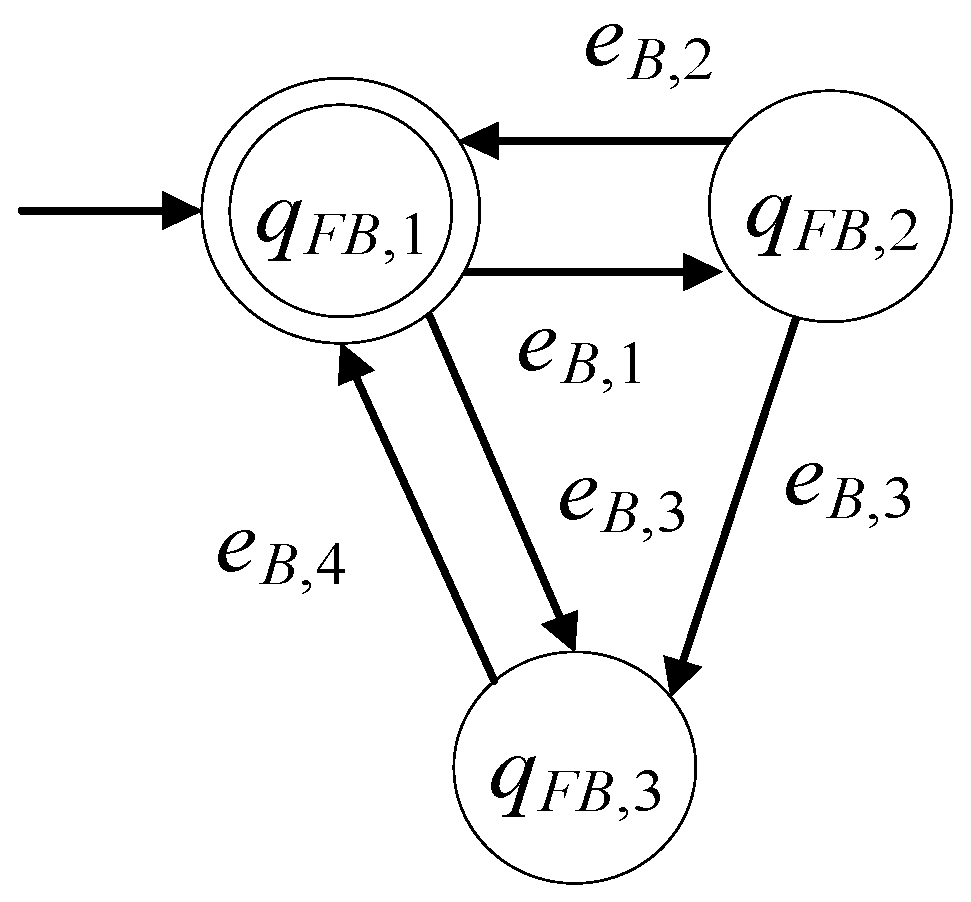
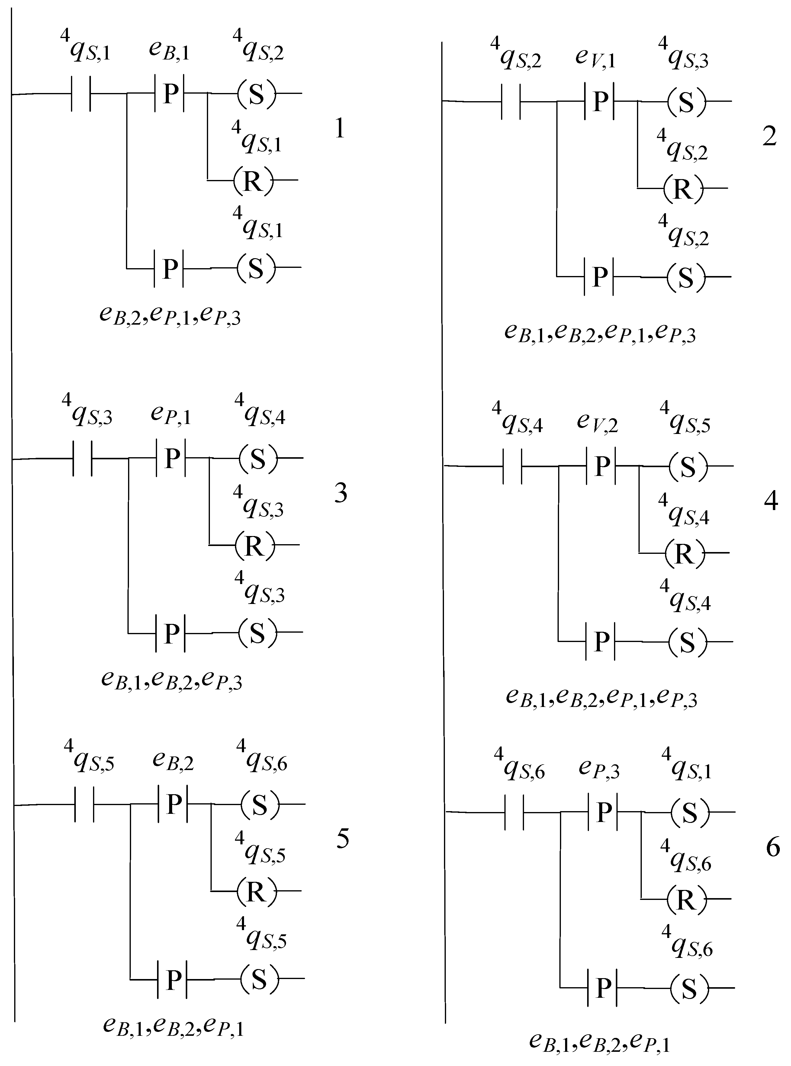
6. Supervisor Implementation

Based on [9,10,11], where the implementation of modular supervisory control schemes in PLC was tackled, it is observed that the parametric expression of the five supervisors, in the present design scheme, facilitates the implementation to local units (i.e., PLCs or PACs). The languages K 1 1 , K 1 2 , K 1 3 , K 2 , and K 3 are realized in the same supervisor form (see Figure 5). This way, five supervisors, namely, the supervisors S 1 1 , S 1 2 , S 1 3 , S 2 , and S 3 can be implemented by a unique function block. This block is proposed to be defined and included in the local library. The supervisor S 4 is implemented by another block. The ladder diagrams of S and S 4 are presented in Figure 7 and Figure 8, respectively. In ladder diagrams, all transitions from each state are grouped. The groups are indexed by the rung number, i.e., in Figure 7 rung 1 indicates the group of all transitions from state q S , 1 and rung 2 indicates the group of all transitions from state q S , 2 . Similarly, in Figure 8 ladder diagram consist of six groups.
Using the methods proposed in [21,22,23,24], it is observed that the present supervisory control scheme is offered for the realization of using the IEC 61499 standard. Using the instructions in [22,24] or even the simulation software “Supremica” (see [23]), the algorithms of the function blocks can easily be developed, and the design of the event execution control is straightforward. Additionally, it is mentioned that the three subsystems of the plant are shuffled, and only the valve has controllable events (automaton G F V ). Thus, the supervisory control algorithm is implementable via quite simple programs, while only a few events are interconnected between the control device of each subsystem. In particular, S 1 1 can be implemented as a local supervisor of G F V , while events not included in the alphabet of S 1 1 (external events) are not required. The supervisor S 1 2 can be implemented as a local supervisor of G F V , and the availability of the “external” events e B , 3 and e B , 4 is required. The supervisor S 1 3 can be implemented as local a supervisor of G F V , and the availability of the “external” events e P , 5 and e P , 6 is required. The supervisor S 2 can be implemented as a local supervisor of G F V , and the availability of the “external” events e P , 1 , e P , 3 , and e P , 6 are necessary. The supervisor S 3 can be implemented as a local supervisor of G F V and the availability of the “external” events e P , 2 , e P , 4 , and e P , 6 is required. Finally, S 4 can be implemented as a local supervisor of G F V , and the availability of the “external” events e B , 1 , e B , 2 , e P , 2 , e P , 1 , and e P , 3 is required.

7. Conclusions

In the present paper, the issue of the preservation of the efficient functionality of a pressurized reactor unit in the presence of actuator and sensor faults was studied. Considering the presence of faults, the pressurized reactor unit was modeled through the modeling of its subsystems in the form of six-tuple finite deterministic automata. The desired behavior of the reactor unit was analyzed into appropriate rules and translated into a set of prefixed closed, regular, desired languages. A modular supervisory control scheme, based on the desired languages, was developed. The controllability of the proposed languages and the nonblocking property of the controlled automaton were proven. The complexities of the derived supervisors and the overall modular supervisory design scheme were computed. The PLC implementations of the derived supervisors were presented in the form of ladder diagrams. It was mentioned that the complexity of the supervisors was low. In addition, it is important to mention that the supervisors are offered for implementation in the form of function blocks in the framework of the IEC 61499 standard.
The issue of the influence of the present supervisors on a gas pipeline network, interconnected with a pressurized gas reactor unit, is currently under investigation. A future perspective of the present results is the extension to larger and more complex reactor units.

Author Contributions

Conceptualization, F.N.K., D.G.F., and G.F.F.; Methodology, F.N.K. and D.G.F.; Validation, F.N.K. and G.F.F.; Investigation, D.G.F. and I.K.; Resources, D.G.F.; Data curation, D.G.F. and I.K.; Writing—original draft preparation, F.N.K. and D.G.F.; Writing—review and editing, D.G.F. and I.K.; Supervision, F.N.K. and G.F.F.; Project administration, F.N.K., D.G.F. and G.F.F. All authors have read and agreed to the published version of the manuscript.

Funding

This research received no external funding.

Conflicts of Interest

The authors declare no conflict of interest.

References

  1. Rotstein, G.E.; Lavie, R.; Lewin, D.R. Automatic Synthesis of Batch Plant Procedures. A Process-Oriented Approach. AIChE J. 1994, 40, 1650–1664. [Google Scholar] [CrossRef]
  2. Koumboulis, F.N.; King, R.E.; Stathaki, A. Logic-Based Switching Controllers—A stepwise safe switching approach. Inf. Sci. 2007, 177, 2736–2755. [Google Scholar] [CrossRef]
  3. Sanchez, A.; Rotstein, G.; Alsop, N.; Macchietto, S. Synthesis and implementation of procedural controllers for event-driven operations. AIChE J. 1999, 45, 1753–1775. [Google Scholar] [CrossRef]
  4. Sanchez, A.; Douriet, J.G.; Ramirez, E. Synthesis of a Class of Discrete-Event Controllers for Large Manufacturing Systems. IEEE Trans. Syst. Man Cybern. Part C Appl. Rev. 2007, 37, 662–669. [Google Scholar] [CrossRef]
  5. Dimitriadis, V.D.; Shah, N.; Pantelides, C.C. Modeling and safety verification of discrete/continuous processing systems. AIChE J. 1997, 43, 1041–1059. [Google Scholar] [CrossRef]
  6. Sanchez, A.; Douriet, J. Efficient Synthesis of a Class of Discrete-Event Controllers for Forced Actions. IFAC Proc. Vol. 2004, 37, 265–270. [Google Scholar] [CrossRef]
  7. Wonham, W.M.; Kai, C. Supervisory Control of Discrete-Event Systems; Springer: Cham, Switzerland, 2019. [Google Scholar] [CrossRef]
  8. Cassandras, C.G.; Lafortune, S. Introduction to Discrete Event Systems, 2nd ed.; Springer: New York, NY, USA, 2008. [Google Scholar] [CrossRef]
  9. Lu, X.; Piétrac, L.; Niel, E. A new approach of modeling supervisory control for manufacturing systems based on SysML. In Proceedings of the 2017 22nd IEEE International Conference on Emerging Technologies and Factory Automation (ETFA), Limassol, Cyprus, 12–15 September 2017. [Google Scholar]
  10. Vieira, A.D.; Santos, E.A.P.; de Queiroz, M.H.; Leal, A.B.; Neto, A.D.D.P.; Cury, J.E.R. A Method for PLC Implementation of Supervisory Control of Discrete Event Systems. IEEE Trans. Control Syst. Technol. 2016, 25, 175–191. [Google Scholar] [CrossRef]
  11. Queiroz, M.H.; Cury, J.E.R. Synthesis and implementation of local modular supervisory control for a manufacturing cell. In Proceeding of the IFAC 6th International Workshop in Discrete Event System, Zaragoza, Spain, 4 October 2002. [Google Scholar]
  12. Morgenstern, A.; Schneider, K. Using Model Checking to Solve Supervisor Synthesis Problems. In Proceedings of the 44th IEEE Conference on Decision and Control, Seville, Spain, 15 December 2005; pp. 2757–2762. [Google Scholar]
  13. Göbe, F.; Ney, O.; Kowalewski, S. Reusability and modularity of safety specifications for supervisory control. In Proceedings of the 2016 IEEE 21st International Conference on Emerging Technologies and Factory Automation (ETFA), Berlin, Germany, 6–9 September 2016; pp. 1–8. [Google Scholar]
  14. Göbe, F.; Aydin, S.; Kowalewski, S. Applicability of supervisory control theory for the supervision of PLC programs. In Proceedings of the 2017 22nd IEEE International Conference on Emerging Technologies and Factory Automation (ETFA), Limassol, Cyprus, 12–15 September 2017; pp. 1–8. [Google Scholar]
  15. Sampath, M.; Sengupta, R.; LaFortune, S.; Sinnamohideen, K.; Teneketzis, D.C. Failure diagnosis using discrete event models. IEEE Trans. Control Syst. Technol. 1996, 4, 105–124. [Google Scholar] [CrossRef]
  16. Wen, Q.; Kumar, R.; Huang, J.; Liu, H. A Framework for Fault-Tolerant Control of Discrete Event Systems. IEEE Trans. Autom. Control 2008, 53, 1839–1849. [Google Scholar] [CrossRef]
  17. Su, R. Supervisor synthesis to thwart cyber attack with bounded sensor reading alterations. Automatica 2018, 94, 35–44. [Google Scholar] [CrossRef]
  18. Gao, C.; Seatzu, C.; Li, Z.; Giua, A. Multiple Attacks Detection on Discrete Event Systems. In Proceedings of the 2019 IEEE International Conference on Systems, Man and Cybernetics (SMC), Bari, Italy, 6–9 October 2019. [Google Scholar] [CrossRef]
  19. Thramboulidis, K. IEC 61499 in Factory Automation. In Advances in Computer, Information, and Systems Sciences, and Engineering; Springer: Dordrecht, The Netherlands, 2006. [Google Scholar] [CrossRef]
  20. Pinto, L.I.; Leal, A.B.; Rosso, R.S.U. Safe dynamic reconfiguration through supervisory control in IEC 61499 com-pliant systems. In Proceedings of the 2017 IEEE 15th International Conference on Industrial Informatics (INDIN), Emden, Germany, 24–26 July 2017; pp. 753–758. [Google Scholar]
  21. Leitão, H.A.S.; Rosso, R.S.U.; Leal, A.B.; Zoitl, A. Fault Handling in Discrete Event Systems Applied to IEC 61499. In Proceedings of the 2020 25th IEEE International Conference on Emerging Technologies and Factory Automation (ETFA), Vienna, Austria, 8–11 September 2020. [Google Scholar]
  22. Cengic, G.; Akesson, K.; Lennartson, B.; Yuan, C.; Ferreira, P. Implementation of full synchronous composition using IEC 61499 function blocks. In Proceedings of the IEEE International Conference on Automation Science and Engineering, Edmonton, AB, Canada, 1–2 August 2005; pp. 267–272. [Google Scholar] [CrossRef]
  23. Akesson, K.; Fabian, M.; Flordal, H.; Malik, R. Supremica—An integrated environment for verification, synthesis and simulation of discrete event systems. In Proceedings of the 2006 8th International Workshop on Discrete Event Systems, Ann Arbor, MI, USA, 10–12 July 2006; pp. 384–385. [Google Scholar]
  24. Cengic, G.; Ljungkrantz, O.; Akesson, K. Formal Modeling of Function Block Applications Running in IEC 61499 Execution Runtime. In Proceedings of the 2006 IEEE Conference on Emerging Technologies and Factory Automation, Prague, Czech, 20–22 September 2006; pp. 1269–1276. [Google Scholar] [CrossRef]
  25. Koumboulis, F.N.; Fragkoulis, D.G.; Menexis, A.N. Supervisory control for flexibility of production manufacturing processes. In Proceedings of the IEEE 21st International Conference on Intelligent Engineering Systems 2017 (INES 2017), Larnaca, Cyprus, 20–23 October 2017. [Google Scholar]
  26. Koumboulis, F.N.; Fragkoulis, D.G.; Ioannou, K.A. Control of Router Nodes in Production Manufacturing Processes. In Proceedings of the 2018 7th International Conference on Systems and Control (ICSC), Valencia, Spain, 24–26 October 2018; pp. 372–377. [Google Scholar] [CrossRef]
  27. Koumboulis, F.N.; Fragkoulis, D.G.; Michalainas, V.C. Modular supervisory control for mining process elevator systems. In Proceedings of the International Conference on Modern Circuits and Systems Technologies (MOCAST), Thessaloniki, Greece, 4–6 May 2017. [Google Scholar]
  28. Koumboulis, F.N.; Fragkoulis, D.G.; Diveris, G.K. Function Supervisors for Storage Systems. In Proceedings of the International Conference on Modern Circuits and Systems Technologies (MOCAST), Thessaloniki, Greece, 7–9 May 2018. [Google Scholar]
  29. Guo, L.; Vincentelli, A.S.; Pinto, A. A complexity metric for concurrent finite state machine based embedded software. In Proceedings of the 8th IEEE International Symposium on Industrial Embedded Systems (SIES), Porto, Portugal, 19–21 June 2013. [Google Scholar]
Figure 1. Schematic of the subsystems of the reactor unit.
Electronics 11 02534 g001
Figure 2. The state diagram of the automaton of the valve including fault.
Electronics 11 02534 g002
Figure 3. The state diagram of the automaton of the switch including faults.
Electronics 11 02534 g003
Figure 4. The state diagram of the pressure sensor including faults.
Electronics 11 02534 g004
Figure 5. State diagram of S.
Electronics 11 02534 g005
Figure 6. State diagram of 4S.
Electronics 11 02534 g006
Figure 7. Ladder diagram of S.
Electronics 11 02534 g007
Figure 8. Ladder diagram of 4S.
Electronics 11 02534 g008
Table 1. A simulation of the transitions of the total automaton.
EventState of the Total AutomatonDescription (Valve, Switch, Sensor)
( q F V , 1 , q F B , 1 , q F P , 1 ) (Closed, Off, Low)
e B , 1 ( q F V , 1 , q F B , 2 , q F P , 1 ) (Closed, On, Low)
e V , 1 ( q F V , 2 , q F B , 2 , q F P , 1 ) (Opened, On, Low)
e P , 1 ( q F V , 2 , q F B , 2 , q F P , 2 ) (Opened, On, Medium)
e P , 2 ( q F V , 2 , q F B , 2 , q F P , 3 ) (Opened, On, High)
e V , 2 ( q F V , 1 , q F B , 2 , q F P , 3 ) (Closed, On, High)
e V , 1 ( q F V , 2 , q F B , 2 , q F P , 3 ) (Opened, On, High)
e P , 4 ( q F V , 2 , q F B , 2 , q F P , 2 ) (Opened, On, Medium)
e B , 2 ( q F V , 2 , q F B , 1 , q F P , 2 ) (Opened, Off, Medium)
e P , 2 ( q F V , 2 , q F B , 1 , q F P , 3 ) (Opened, Off, High)
e V , 2 ( q F V , 1 , q F B , 1 , q F P , 3 ) (Closed, Off, High)
e P , 5 ( q F V , 1 , q F B , 1 , q F P , 4 ) (Closed, Off, Faulty)
e B , 1 ( q F V , 1 , q F B , 2 , q F P , 4 ) (Closed, On, Faulty)
e V , 1 ( q F V , 2 , q F B , 2 , q F P , 4 ) (Opened, On, Faulty)
e P , 6 ( q F V , 2 , q F B , 2 , q F P , 1 ) (Opened, On, Low)
Table 2. Simulation of the controlled automaton.
EventState of the Controlled AutomatonDescription (Valve, Switch, Sensor)
( q F V , 1 , q F B , 1 , q F P , 1 ) (Closed, Off, Low)
e B , 1 ( q F V , 1 , q F B , 2 , q F P , 1 ) (Closed, On, Low)
e V , 1 ( q F V , 2 , q F B , 2 , q F P , 1 ) (Opened, On, Low)
e P , 1 ( q F V , 2 , q F B , 2 , q F P , 2 ) (Opened, On, Medium)
e P , 2 ( q F V , 2 , q F B , 2 , q F P , 3 ) (Opened, On, High)
e V , 2 ( q F V , 1 , q F B , 2 , q F P , 3 ) (Closed, On, High)
e V , 1 ( q F V , 1 , q F B , 2 , q F P , 3 ) (Closed, On, High)
e P , 4 ( q F V , 1 , q F B , 2 , q F P , 2 ) (Closed, On, Medium)
e B , 2 ( q F V , 1 , q F B , 1 , q F P , 2 ) (Closed, Off, Medium)
e P , 2 ( q F V , 1 , q F B , 1 , q F P , 3 ) (Closed, Off, High)
e V , 2 ( q F V , 1 , q F B , 1 , q F P , 3 ) (Closed, Off, High)
e P , 5 ( q F V , 1 , q F B , 1 , q F P , 4 ) (Closed, Off, Faulty)
e B , 1 ( q F V , 1 , q F B , 2 , q F P , 4 ) (Closed, On, Faulty)
e V , 1 ( q F V , 1 , q F B , 2 , q F P , 4 ) (Closed, On, Faulty)
e P , 6 ( q F V , 1 , q F B , 2 , q F P , 1 ) (Closed, On, Low)
Publisher’s Note: MDPI stays neutral with regard to jurisdictional claims in published maps and institutional affiliations.

