Abstract
The feeder terminal unit (FTU) is a critical component of any electric power system that works in a complex electromagnetic environment. However, innovative research of theoretical analysis of electromagnetic–thermal practices inside the FTU system is missing in the literature. This work presents the theoretical methodologies for calculating and analyzing the electromagnetic–thermal influence of FTUs in a high-power electromagnetic (HPEM) environment. The numerical outcomes reveal that the surface of the FTU and connecting cables under powerful electromagnetic pulses (EMP) induce significant electromagnetic fields and high temperatures. Significantly, the electromagnetic pulse and injection of heat through the wires into the FTU may cause interference and possibly damage to the FTU’s circuits and electronics. This work serves as a reference for electromagnetic compatibility (EMC) design of FTUs and provides numerical analysis for ensuring the normal operation of FTU devices under harsh electromagnetic environments.
1. Introduction
The feeder terminal unit (FTU) is an intelligent electronic device designed for the use in feeder automation to collect data from hundreds of feeders and transmit them to the control center [1,2,3]. It has been applied in distribution automation for fault detection, prediction, isolation, and service restoration. In the electric power environment, high-power electromagnetic interferences are increasingly common. These electromagnetic interferences have a serious impact on the surrounding electronic and electrical equipment and may even endanger the safety of workers. Furthermore, because most of these switching devices use pulse width modulation (PWM) technology, their output voltage and current power spectrum are discrete, which will produce a large number of high-order harmonic components related to the switching frequency, causing electromagnetic pollution in the power grid. Therefore, electromagnetic interference analysis of FTUs under a harsh electromagnetic environment becomes more and more important. However, the design and optimization of FTUs currently still relies on time-consuming trial-and-error procedures, engineering experience, and few available measured surface temperature data. Although the electromagnetic interference problem of FTUs need to be solved urgently, research in this area is still in the development stage due to the particularity and complexity of the FTU electromagnetic compatibility.
With the increased computer power and the development of computational methods, numerical simulation has become an effective and alternative tool for better understanding the electromagnetic induction heating process in the integrated circuit (IC) industry [4,5,6,7,8,9]. Electromagnetic and thermal multi-physics numerical simulation algorithms [10,11,12,13,14] for complex three-dimensional (3D) ICs with power supply structures (such as PDN) or cooling structures (such as heat sink, microchannel, etc.) to provide accurate electromagnetic and temperature distribution are the focus of academic and industrial circles and also the research hot spot of the IC simulation industry [15,16,17,18,19,20,21]. However, little information regarding 3D theoretical analysis of electromagnetic–thermal phenomena inside the FTU system has been reported. Under a high-power electromagnetic (HPEM) environment [22,23], the electromagnetic fields may couple the cables and inject into the interior of the FTU and then generate resonance in the internal cavity, which makes the surface temperature of the high-density ICs inside the FTU rise sharply, resulting in interference and even destruction of the performance of internal circuit and electronic devices. Because the electromagnetic induction and tempering features inside the FTU system have not been better addressed, it is important to develop a robust transient electromagnetic–thermal algorithm and apply it to analyze FTU multi-physics behavior.
In this paper, we introduce a 3D electromagnetic–thermal mathematical model coupling Maxwell’s equations and the heat conduction equation. Based on the finite element analysis tool, the electromagnetic–thermal effect of an FTU system under a HPEM environment is analyzed.
The remainder of this paper is divided as follows. Section 2 summarizes the relevant formulae for simulating the multi-physics properties of FTU. Section 3 gives a series of numerical examples for analyzing the electromagnetic–thermal effect of FTU under a high-power electromagnetic environment. Finally, Section 4 briefly concludes this paper.
2. Methodology
The induction heating process for the FTU can be modeled as a coupled electromagnetic–thermal problem. The mathematical analysis of electromagnetic fields can be carried out by solving the frequency–domain Maxwell’s equations.
where is the magnetic field intensity, is the electric field intensity, the constant is the angular frequency, is the wave number, and are relative permittivity and relative permeability, respectively, denotes the permeability for free space, and represents applied electric current density.
After testing Maxwell’s equation by the Galerkin scheme, the discretized system equations can be effectively solved using the finite element method (FEM) method. Note that, under ideal conditions, the electromagnetic power dissipation is completely converted to heat. Thus, the volumetric heat source generated by the eddy current due to the Joule effect can be calculated:
where eddy current density vector can be used to update the temperature and electromagnetic parameters of the material to realize the bidirectional coupling of electromagnetic and heat fields.
The governing equation of heat conduction can be expressed as
where is the density of the material, is the specific heat, k is the thermal conductivity, and T is the temperature. With appropriate boundary conditions [16], this equation can still be solved by the finite element time-domain (FETD) method.
The co-simulation work flow of the electromagnetic–thermal coupling process can be described briefly: Frequency–domain electromagnetic fields are first calculated by solving Maxwell’s equations. The dissipated power is characterized numerically, and it serves as the heat source for thermal simulation. The temperature profile is obtained at the end of each iteration step, and it is used to update all temperature-dependent material parameters in the structures.
3. Analysis of the Electromagnetic–Thermal Effect of the FTU
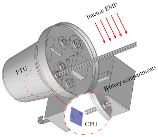
In a complex electric power environment, FTU systems may face high-power microwave interference and high-voltage arc discharge, and even need to be able to shield from lightning strikes. In this section, we utilize numerical simulation tools to analyze the problems of FTU systems exposed to the HPEM environment. Typical FTU structures include battery compartments, metal housings, and internal circuits and chips, as shown in Figure 1. The questions we are interested in are: (1) What is the electromagnetic intensity and surface temperature on the connecting cables and metal housing when an intense electromagnetic pulses (EMP) impacts on the outer surface of the FTU. (2) Whether electromagnetic waves can inject into the FTU and whether electronic equipment can be electromagnetic interfered with or heated up.

Figure 1.
An intense EMP impacts on the FTU system.
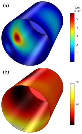
In the numerical simulation, the metal housing of the FTU and other small structures (such as cable joints, fixing screws, etc.) are made of ferroalloy with electrical conductivity of 1.2 × 10, coefficient of thermal conductivity of 56 , and heat capacity at constant pressure of 440 . The connecting cables are made of copper with electrical conductivity of 6 × 10, coefficient of thermal conductivity of 400 , and heat capacity at constant pressure of 385 . A high-power Gaussian electromagnetic pulse with 0.7 is vertically irradiated onto the surface of the connecting cables, and the electromagnetic–thermal co-simulation results are shown in Figure 2.

Figure 2.
Electromagnetic–thermal distribution on the FTU: (a) magnetic field distribution on the FTU; (b) thermal distribution on the FTU.
We can see that strong induced electromagnetic fields are generated on the cables and FTU surface. Due to direct exposure to an intense electromagnetic pulse, the magnetic field intensity at the cable reaches 26.5 A/cm, and the electric field intensity reaches 5 kV/cm, as shown in Figure 2a. In addition, because the FTU metal housing and cables are consumable, the induced current is further converted into thermal energy, as shown in Figure 2b. In five seconds of irradiation, the temperature of the cables and FTU metal housing rises to approximately 260 C. Predictably, in the complex high-power electromagnetic environment, the electromagnetic interference and heat of the FTU housing will have a serious impact on the performance of the electronic and electrical equipment inside, which may even burn out due to overheating.
Because there is induced current in the cable that will generate induced field and further inject into the FTU, the induced electromagnetic waves will oscillate in the FTU’s internal cavity and may produce electromagnetic interference to internal circuits and chips. Figure 3a shows the electric field distribution on the inner surface of the FTU. As we can see, up to 0.55 kV/cm of electric field intensity can be generated on the inner surface of the FTU, which is much stronger than the standard of a high-power electromagnetic environment that was defined by the International Electrotechnical Commission (IEC), which refers to the electromagnetic environment in which the electric field intensity exceeds 0.001 kV/cm. It can be seen that, if the FTU electromagnetic package is not designed efficiently, the electromagnetic interference signal injected from the outside could easily cause a sudden increase in energy density, which will have a serious impact on the electronic and electrical equipment inside the FTU. In addition, the electromagnetic field injected through the cable may also raise the temperature of the FTU’s inner wall, but the temperature increase is not significant because of the low leakage of electromagnetic waves inside the FTU, as shown in Figure 3b.

Figure 3.
Electromagnetic–thermal distribution on the FTU internal surface: (a) electric field distribution on the FTU internal surface; (b) thermal distribution on the FTU.
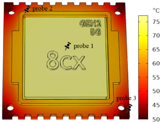
Another question of interest is whether the circuitry or electronic package connected to the cable inside the FTU will heat up. Under the irradiation of an external EMP, we simulated the heating process of a central processing unit (CPU) connected with metal cables (CPU inside the FTU is also shown in Figure 1). It is assumed that the CPU packaging chip is composed of copper alloy, ferroalloy, and PCB substrates. As the cable temperature increases, energy is transferred rapidly to the CPU center and a heating process occurs, as shown in Figure 4. When the irradiation time reaches five seconds, the heated cable causes the CPU temperature to rise sharply, and the central temperature reaches 76 C. However, due to different heat conduction locations and material properties, CPU packaging temperature distribution presents uneven characteristics.

Figure 4.
Thermal distribution on the CPU inside the FTU (contains the locations of three probes).
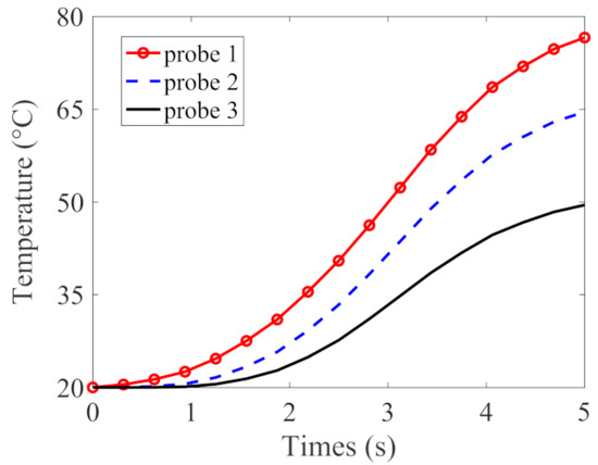
Finally, in order to quantitatively observe the heating process of different materials, we set up three probes on different CPU parts. Probe 1 is placed in the copper alloy, which is located in the center of the packaging structure; probe 2 is placed in the ferroalloy, which is located around the package structure; and probe 3 is placed in the PCB substrate, which is located at the bottom of the package structure. As shown in Figure 5, the temperature of all three probes increased with time. However, because the copper alloy is located in the center of heat conduction and has the highest thermal conductivity, the temperature of probe 1 rises rapidly from room temperature to 76 C. The PCB substrate has the lowest thermal conductivity and is located at the back of the CPU, thus temperature changes are relatively minimal. It can be seen that the external injection of an intense EMP may easily cause a sudden energy accumulation, which may have a serious impact on the performance of electronic and electrical equipment inside the FTU.

Figure 5.
Temperature changes on three probes on the CPU inside the FTU.
4. Conclusions
This study presented an electromagnetic–thermal coupling simulation technique and utilized efficient multi-physical simulation tools to assess the electromagnetic–thermal effect of the FTU. Under extreme EMP irradiation, numerical studies reveal that the connecting cables and metal housing of the FTU create a large induced current and a high temperature. The induced electromagnetic waves and heating impact of the cables can significantly deteriorates the efficacy of the FTU, resulting in severe interference and even damage to the electronic circuits of the FTU. The proposed work presents a novel approach to provide an optimal and electromagnetic compatible layout.
Author Contributions
Methodology and writing, D.Z.; software, Y.C., Y.W. and Y.Z. (Yang Zhao); validation, Z.F., J.D. and L.W.; writing-review and editing, R.C., Y.Z. (Yan Zhen) and H.Z.; methodology, Y.Z. (Yuanguo Zhou) and Q.R. All authors have read and agreed to the published version of the manuscript.
Funding
This work is supported by the laboratory open fund of Beijing Smart-chip Microelectronics Technology Co., Ltd.
Data Availability Statement
Data are available from the corresponding author upon reasonable request.
Conflicts of Interest
The authors declare no conflict of interest.
Abbreviations
The following abbreviations are used in this manuscript:
| FTU | Feeder Terminal Unit |
| HPEM | High-Power Electromagnetic |
| EMP | Electromagnetic Pulses |
| EMC | Electromagnetic Compatibility |
| CPU | Central Processing Unit |
| IEC | International Electrotechnical Commission |
References
- Hu, H.M.; Shi, Y.J.; Zhang, Y.H.; Fu, Y.L. Study on Power Supply of the Feeder Terminal Equipment. Appl. Mech. Mater. 2014, 672–674, 914–919. [Google Scholar] [CrossRef]
- Kizu, K.; Murakami, H.; Natsume, K.; Tsuchiya, K.; Koide, Y.; Yoshida, K.; Obana, T.; Hamaguchi, S.; Takahata, K. Manufacturing design and development of the current feeders and coil terminal boxes for JT-60SA. Fusion Eng. Des. 2015, 98–99, 1094–1097. [Google Scholar] [CrossRef]
- Han, G.Z. Harmonization of Feeder Terminal Unit Information Model Based on IEC 61850 and IEC 61968/61970. Appl. Mech. Mater. 2013, 411–414, 1787–1790. [Google Scholar] [CrossRef]
- Li, E.P. Electrical Modeling and Design for 3D Integration: 3D Integrated Circuits and Packaging. In Signal Integrity Power Integrity and EMC; Wiley: Hoboken, NJ, USA, 2012. [Google Scholar]
- Zeng, K.; Jiao, D. Matrix-free method for transient maxwell-thermal cosimulation in arbitrary unstructured meshes. IEEE Trans. Microw. Theory Tech. 2018, 66, 5439–5448. [Google Scholar] [CrossRef]
- Xie, J.; Xie, B.; Swaminathan, M. Electrical-thermal modeling of through-silicon via (TSV) arrays in interposer. Int. J. Numer. Model. Electron. Netw. Devices Fields 2013, 26, 545–559. [Google Scholar] [CrossRef]
- Huang, W.; Zhang, W.; Chen, A.; Zhang, Y.; Li, M. A co-simulation method based on coupled thermoelectric model for electrical and thermal behavior of the lithium-ion battery. IEEE Access 2019, 7, 180727–180737. [Google Scholar] [CrossRef]
- Xie, J.; Swaminathan, M. Fast electrical-thermal co-simulation using multigrid method for 3D integration. In Proceedings of the IEEE 62nd Electronic Components and Technology Conference, San Diego, CA, USA, 29 May–1 June 2012; pp. 651–657. [Google Scholar]
- Liu, E.X. Multi-physics modeling of through-silicon vias with equivalent-circuit approach. In Proceedings of the IEEE Conference Electrical Performance of Electronic Packaging and Systems (EPEPS), Austin, TX, USA, 25–27 October 2010; pp. 33–36. [Google Scholar]
- Dong, Y.; Tang, M.; Li, P.; Mao, J. Transient Electromagnetic-Thermal Simulation of Dispersive Media Using DGTD Method. IEEE Trans. Electromagn. Compat. 2019, 61, 1305–1313. [Google Scholar] [CrossRef]
- Chen, P.Y.; Zhang, H.H.; Sha, W.E.I.; Ding, D.Z. Transient Electromagnetic-thermal Co-Simulation Based on DGTD Method. In Proceedings of the 2019 International Applied Computational Electromagnetics Society Symposium, Nanjing, China, 8–11 August 2019; pp. 1–2. [Google Scholar]
- Zhang, H.-X.; Huang, L.; Wang, W.-J.; Zhao, Z.-J.; Zhou, L.; Chen, W.; Zhou, H.; Zhan, Q.; Kolundzija, B.; Yin, W.-Y. Massively Parallel Electromagnetic–Thermal Cosimulation of Large Antenna Arrays. IEEE Antennas Wirel. Propag. Lett. 2020, 19, 1551–1555. [Google Scholar] [CrossRef]
- Lu, Y.; Chen, J.; Li, J.; Xu, W. A Study on the Electromagnetic-Thermal Coupling Effect of Cross-Slot Frequency Selective Surface. Materials 2022, 15, 640. [Google Scholar] [CrossRef] [PubMed]
- Liu, H.; Wang, X.; Si, L.; Gong, J. Numerical simulation of 3D electromagnetic-thermal phenomena in an induction heated slab. J. Iron Steel Res. Int. 2020, 27, 420–432. [Google Scholar] [CrossRef]
- Tan, E.L.; Heh, D.Y. Stability analyses of nonuniform time-step LOD-FDTD methods for electromagnetic and thermal simulations. IEEE J. Multiscalemultiphys. Comput. Techn. 2017, 2, 183–193. [Google Scholar] [CrossRef]
- Lu, T.; Jin, J.-M. Electrical-thermal co-simulation for analysis of high-power RF/Microwave components. IEEE Trans. Electromagn. Compat. 2017, 59, 93–102. [Google Scholar] [CrossRef]
- Xue, Y.; Mi, J.; Wen, P.; Ren, Q.; Zhou, Y. Efficient Transient Thermal Analysis Based on Spectral Element Time Domain Method with Curvilinear Hexahedrons. Int. J. Numer. Model. El. 2021, 34, e2814. [Google Scholar] [CrossRef]
- Xie, J.; Swaminathan, M. Electrical-thermal cosimulation with non-conformal domain decomposition method for multiscale 3-D integrated systems. IEEE Trans. Compon. Packag. Manuf. Technol. 2014, 4, 588–601. [Google Scholar] [CrossRef]
- Lu, T.; Jin, J.-M. Electrical-thermal co-simulation for DC IR-drop analysis of large-scale power delivery. IEEE Trans. Compon. Packag. Manuf. Technol. 2014, 4, 323–331. [Google Scholar] [CrossRef]
- Lu, T.; Jin, J.-M. Thermal-aware high-frequency characterization of large-scale through-silicon-via structures. IEEE Trans. Compon. Packag. Manuf. Technol. 2014, 4, 1015–1025. [Google Scholar] [CrossRef]
- Xue, Y.; Ren, Q.; Chen, J.; Zhou, Y. Transient Electromagnetic-Thermal Cosimulation for Micrometer-Level Components. IEEE Trans. Microw. Theory Techn. 2021, 69, 4341–4351. [Google Scholar] [CrossRef]
- Giri, D.V.; Hoad, R.; Sabath, F. High-Power Electromagnetic Effects on Electronic Systems; Artech: Tuen Mun, Hong Kong, China, 2020. [Google Scholar]
- Giri, D.V.; Tesche, F.M.; Baum, C.E. An overview of high-power electromagnetic (HPEM) radiating and conducting systems. URSI Radio Sci. Bull. 2006, 2006, 6–12. [Google Scholar]
Publisher’s Note: MDPI stays neutral with regard to jurisdictional claims in published maps and institutional affiliations. |
© 2022 by the authors. Licensee MDPI, Basel, Switzerland. This article is an open access article distributed under the terms and conditions of the Creative Commons Attribution (CC BY) license (https://creativecommons.org/licenses/by/4.0/).