Abstract
In this study, the contouring control problem of a five-axis machine tool was examined. Due to the rotation axes, there are two coordinate systems involved in the five-axis machine tool, namely the workpiece coordinate system and machine coordinate system. The five-axis machine tool is required to follow a given desired path with tool orientation specified in the workpiece coordinate system. However, the system dynamics of the machine tool is described in the machine coordinates. Kinematic transformations exist between the two coordinate systems. One challenge of the problem is to design a controller in the machine coordinate system that will meet the requirements in the workpiece coordinate system. Another challenge is to minimize both the position contour error and tool orientation error. The method of equivalent errors is adopted to design the contouring controller. The desired path and tool orientation in the workpiece coordinate system are transformed into a five-dimensional hyper-curve in the machine coordinate system. A contouring controller was designed to follow the five-dimensional hyper-curve using the method of equivalent errors. Both numerical and experimental results validate the effectiveness of the proposed contouring control method.
1. Introduction
In recent decades, computer numerical controlled (CNC) manufacturing has developed dramatically and is aiming to develop more functionalities, adaptability, intelligence, etc. [1]. Contouring control is a special type of motion control that is important for multi-axis motion systems such as the CNC manufacturing system. Given a desired path, it is required that the motion system follow the path precisely. In other words, the objective of contouring control is to reduce, by as much as possible, the contour error, which is defined as the distance from the actual position of the motion system to the command path. This problem is fundamentally different from the common tracking control problem, which relates to reducing the tracking error, defined by the distance between the actual and command positions. It is well known that the contouring performance may not be achieved by simply reducing the tracking error. The contouring control problem can be found in a wide variety of applications, including the machining task in a multi-axis machine tool, where the machining accuracy depends solely on the contour error.
Many contouring control methods have been proposed for the multi-axis motion system. The contouring control of two- or three-axis machine tools has been well developed [2,3,4,5,6,7]. The first notable method is the cross-coupled controller (CCC) [8,9,10]. This directly compensates for the contour errors by estimating the contour error with the tracking errors of each axis. However, CCC has some limitations. First, it is limited to two- or three-axis systems. Second, linear and circular paths are preferred. Complicated free-form paths need to be approximated by linear segments and/or circular arcs, which possess larger errors, leading to poor contouring performance. To overcome this difficulty, coordinate transformation methods have been proposed, such as the task coordinate frame method [7,11].
The rapid development of modern industry has led to the high demand for manufacturing system’s having high efficiency and high accuracy. To meet this demand, the five-axis machine tool is widely used in the manufacture of complicated parts for the automotive industry, shipbuilding, the space industry, etc. For the five-axis machine tool, the contouring control problem is more complicated, and involves not only the position contour error, but also the tool orientation error. The position contour error is the normal deviation in the tool tip and the orientation error is the normal deviation in the tool axis orientation. In general, the conventional approach treats the position contour error and tool orientation error separately [12,13]. In [13], two independent controllers were designed for reducing the two different errors: one is the tool tip sliding mode contour controller and the other is the tool orientation contour controller.
However, the position contouring dynamics and orientation dynamics are coupled. To achieve better performance, the two controllers should be designed together in an integrated way. A five-axis machine tool involves the workpiece coordinate system and machine coordinate system. It is required to follow a given desired path, with the tool orientation specified in the workpiece coordinate system. However, the system dynamics of the machine tool is described in the machine coordinates. Kinematic transformations exist between the two coordinate systems. The desired path with tool orientation in the workpiece coordinate system are transformed into a five-dimensional (5-D) hyper-curve in the machine coordinate system; that is, the five-axis machine tool needs to follow a 5-D command path in the machine coordinate frame. In this paper, an integrated contouring controller for the five-axis machine tool is proposed with the method of equivalent errors [14,15]. For an n-axis motion system, one can define n equivalent errors, where there are (n − 1) equivalent contour errors and one tangential error. The definition of equivalent contour errors utilizes the algebraic equations representing the command path. The present system comprises four equivalent contour errors and one tangential error. The 5-DOF system dynamics are transformed into the dynamics of equivalent errors. Then, a controller was designed to stabilize the error dynamics; that is, one can transform the contouring control problem into the stabilization problem for easier design of the complicated contouring controller.
This paper is organized as follows. The problem formulation and system modeling are presented in Section 2. Section 3 introduces the method of equivalent errors and the design of the contouring controller. Simulation results are shown in Section 4 and experimental results are presented in Section 5. Finally, conclusions are drawn in Section 6.
2. Kinematics and Dynamic Modeling of the Machine Tool
This section is concerned with the dynamic model establishment in the Yeong-Chin Machinery (YCM) Five-Axis Vertical Machining Center machine tool (NXV560A). It is a rotary type with parallel axes x, y, and z and rotation axes A and C. Figure 1 shows the exploded view of the system with each component. The mass of each component includes the parts of the leadscrew and the motor.
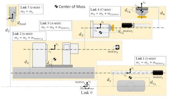
Figure 1.
Exploded view of the five-axis machine (Model: NXV560A).
2.1. Five-Axis Machine Analysis and the Inverse/Forward Kinematics
As shown in Figure 1, it is assumed that the motor and the leadscrew of the motor have no relative movement (translational motion). According to Figure 1, we define the five-axis links, where link 0 is the ground link; link 1 is the y-axis slider-bar component; link 2 is the x-axis slider-bar component; link 3 is the A-axis rotating component; link 4 is the C-axis rotating component; and link 5 is the z-axis slider-bar. Therefore, this mechanism is combined into a set of a four-joint robot (link 1–4) and a spindle slider (link 5). The length between the joints can be clearly defined by each component as shown in Figure 1, denoted by . The location of the mass center of each component is . For the spindle and tool, is the distance between from link 0 (ground link) to link 5 (spindle), and is the total length of the tool and tool holder. The mass of each component is , with , where is the mass of the part body of the x C axis, respectively; is the mass of the spindle; are the masses of the leadscrew and the motor; is the mass of the fixture. The five-axis machine can be represented as a schematic diagram of a mechanism, and the coordinates are defined on each link, as shown in Figure 2.
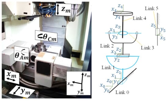
Figure 2.
Schematic diagram of the mechanism.
According to the definition of the coordinates in Figure 2 and parameters in Figure 1, each joint’s coordinate transformation matrix can be obtained as:
where are the machine coordinates. Here and subsequently, the subscript m is used to denote the machine coordinates and w is used to denote the workpiece coordinates. Here, represents the homogeneous transformation matrix from link i to link j [16]. Hence, involves only the translation of the y-axis and involves only the translation of the x-axis. involves the rotation of the A-axis, which will also induce some translation of the coordinate. involves the rotation of the C-axis. Finally, involves only the translation of the z-axis. Thus, the forward and inverse kinematics can be obtained by:
where is the coordinate transformation from the workpiece (link 4) to tool center point. Now, the forward kinematics can be written as:
where = sin(), , i = A, C; α = ( + + ); = ( − − − ); are workpiece coordinates. From Equation (1), the inverse kinematics can be obtained as:
Suppose that the tool vector in workpiece coordinate system () is defined to be pointed at a fixed point . Then, the tool vector can be represented as:
2.2. Dynamic Equation
The dynamic equation of this system can be obtained using the Euler-Lagrange approach and can be written as [17,18]
where ; is the inertia matrix, is the Coriolis and centrifugal forces matrix; is the gravity force. Equation (4) can be rewritten as
where ; ; is the control input.
3. Equivalent Contour Error Model and Contouring Controller Design
3.1. Equivalent Contour Error for Five-Axis Machine
From Equation (4), one can see that the dynamics of the five-axis machine tool are represented in the five-dimensional generalized coordinates . As discussed in the previous section, the desired commands for the five-axis system are described in the workpiece coordinates, which include the desired path and desired orientation. The contouring control problem of the five-axis system requires: (i) the output position (, ,(the tool center point, TCP) follows the desired path; and (ii) the output tool vector () to be the desired orientation. Thus, it is required not only to reduce the position contour error defined by the distance from the output position to the command path, but also to reduce the orientation error defined by the angle difference between the output tool vector and the desired vector. The conventional approach to this problem is to regard the position contouring and orientation contouring problems as separate problems; thus, their controllers have been designed independently (see, e.g., [13]). However, the dynamics of orientation contouring is in fact coupled with that of position contouring. For better performance, the controller should be designed in an integrated way. To this aim, we reconsider the contouring control problem in the machine coordinates.
In general, a desired path with a desired orientation vector in the workpiece coordinates can be represented by a five-dimensional hyper-curve in the machine coordinates, denoted as S. The contouring control problem of the five-axis system can be restated as: requiring the output position to follow the hyper-curve S (the desired path in machine coordinates). The objective is to minimize the real contour error which is the distance between the actual position and the curve S. With this point of view, we integrated the problem of position contouring and orientation contouring, enabling the design of one integrated contouring controller. In this study, the method of equivalent errors was taken for the design of the contouring controller [14]. The key feature of the method is the concept of equivalent contour error defined in the machine coordinates. In general, the desired path S can be represented by a set of four algebraic equations , where . If the actual output is not on S, it will not satisfy the path equation and a nonzero vector will be generated, as shown in Figure 3. This nonzero vector is called the equivalent contour error.
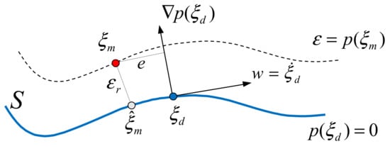
Figure 3.
Actual contour error and equivalent contour error.
Obviously, implies that the actual position is on the desired path and hence . Conversely, if , the actual position should be on the path and hence . Moreover, it is shown in [14] that can be represented by a positive definite quadratic form of ; that is:
for some . Hence, reducing is equivalent to reducing . The proposed method was used to design a controller to minimize the equivalent contour error.
In order to generate the equivalent contour error for the five-axis machine tool, the forward kinematic transformation is needed. Recall that the desired path for TCP and the desired tool orientation vector are described in the workpiece coordinates, as shown in Figure 4. The desired path in the task space can be represented by two equations denoted as and . The tool vector is dependent on the TCP position, such as that given in Equation (3). Since it is a unit vector, we can take two of the three equations to form the path equations denoted as and . The forward kinematics can relate the workpiece coordinates to the machine coordinates as , where is the forward kinematics given by Equation (1). Therefore, one can obtain the path equation in the machine coordinates as:
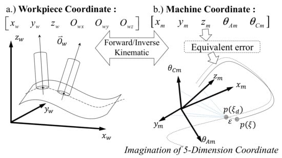
Figure 4.
Coordinate transformation and equivalent error: (a) workpiece coordinate; (b) machine coordinate and equivalent error.
Thus, the equivalent contour error can be defined by .
3.2. Controller Design
In addition to the equivalent contour error, the equivalent errors also include one tangential error for contouring along the trajectory. The tangential error is defined as the projection of the tracking error onto the tangential vector at the command point, i.e., . As a result, the machine coordinates can be transformed into the equivalent errors as
With this transformation Equation (6), the system dynamics, Equation (5), can be transformed into the dynamics of equivalent errors as:
where h = is given by
and
For the error dynamics, Equation(7), one can design a stabilizing controller so that the equivalent errors can be asymptotically stable, which implies that the contour error approaches zero asymptotically. Thus, the contouring control problem becomes a stabilization problem. The configuration of the method of equivalent errors is shown in Figure 5. First, the motion planning for the command path and orientation vector was designed in the workpiece coordinates. Here, the S-type velocity profile is adopted to design the velocity along the desired path [16,19,20]. Then, for the machine coordinates, the commands can be obtained by inverse kinematics, and the path functions can be obtained by forward kinematics. Together with the output position , one can establish the equivalent errors.
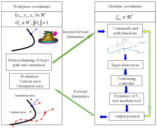
Figure 5.
Configuration of the method of equivalent errors.
Next, the contouring controller can be obtained by designing a stabilizing controller for the error dynamics, Equation(7). Here, the approach of feedback linearization followed by integral sliding mode control (ISMC) is used to design the controller [21,22,23]. Thus, for the dynamics of equivalent errors, Equation (7), we can first design the feedback linearization control as:
where ∈ is a non-singular matrix and v is the new control input to be designed. Then, the closed-loop system becomes
where η = denotes the equivalent error and denotes the uncertainty that cannot be cancelled by the feedback linearization control. Next, an integral sliding manifold is taken as:
The new control input v will contain two parts: equivalent control and switching control , i.e., + . The equivalent control ensures the system stays on the sliding manifold once it is there, when disregarding the uncertainty. That is, will make . By Equations (8) and (9), we have:
which yields:
With the equivalent control, the dynamics of sliding variable with uncertainty become:
Consider a Lyapunov function for a single (the i-th) sliding variable . Here and subsequently, the subscript i indicates the i-th component of a vector. Then, we can obtain:
Assume that ( is the Euclidean -norm), which also implies . The i-th switching control can be designed as:
where is the sign function and is a positive constant. Hence, we have:
which implies that will reach the sliding manifold in finite time. Once it is on the sliding manifold ( for all i), Equation (9) implies that
From Equation (11), the overall switching control can be written as
Finally, combining Equations (10) and (12), the overall ISMC control law is given as
In practical applications, the discontinuous sign function is in general replaced by a smooth function, such as tanh(), to avoid the problem of chattering. Please refer to [24] for more detailed analysis. Finally, the ISMC control law for the present system is given as
where is a boundary layer for the sliding mode. Thus, the overall controller can be obtained as:
where , , , µ are positive control gains. Finally, from the forward kinematics, the output position in the machine coordinates can be used to obtain the TCP and tool vector in the workpiece coordinates. One can then obtain the contour error and orientation error for performance evaluation.
4. Simulation Results and Discussions
The contouring controller of two different paths were numerically investigated. One is a straight line and the other is a circular path. In addition to the method of equivalent errors, the results by the conventional proportional and derivative (PD) controller are also presented for comparison. Thus, there are four cases for the simulation, as listed in Table 1.

Table 1.
The list of simulation cases.
The straight-line path is from X1 = [0.08, 0.03, 0.02] m to X2 = [0.01, 0.05, 0.07] m in the workpiece coordinate frame. The tool’s vector is set as pointing to the fixed point Xc = [0, −0.05, −0.5] m. As mentioned preciously, the S-type velocity profile along the straight line was designed. The total motion time was 2.35 s. For this path, the equivalent errors can be formed as:
where L = ( −)2 + ( −)2 + ( −)2 and (, , can be expressed as functions of the machine coordinates using the forward kinematics, Equation (1). In Equation (13), the functions of and represent two planes parallel to the -axis and -axis, respectively. Their intersection in 3-D space is the straight line passing through X1 and X2. From Equation (3), we have
From the forward kinematics (1), we have
Therefore, we can get
which is used to define the third equivalent contour error . Again, from Equations (1) and (3), one can also obtain:
which is used to define the fourth equivalent contour error .
For the circular path in the workpiece coordinate frame, the center is at the origin with the radius of 0.1 m. The circle is inclined 45° to the -axis. The tool’s orientation vector is pointed to the fixed point Xc = [0, 0.8, −0.8] m from the current position. Again, the S-type velocity profile along the circle was designed. The total motion time was also planned to be 2.35 s. For this path, the equivalent errors can be formed as
where r = 0.1 m is the radius of the circle, and (, , can be expressed as functions of the machine coordinates using the forward kinematics, Equation(1). The first equivalent contour error represents an elliptical cylinder parallel to the -axis. The second equivalent contour error represents a plane parallel to the - axis. The second equivalent contour error represents a plane parallel to the -axis with a tilted angle of 45°. Their intersection in 3-D space is the circle of the desired path. The third and fourth equivalent contour errors can be obtained exactly as in the case of a straight line.
In the numerical simulations, the PD-controller gains (Kp, Kd) and the and the ISMC control gains (b1, b2,, µ) for the linear and circular paths are listed in the Table 2. The sampling time for the simulations is set to 1 ms. The simulation results are shown in Figure 6 and Figure 7, where the position contour errors for all cases are shown in Figure 6 and the orientation errors are presented in Figure 7. For case 1, which is the straight-line path with the PD controller, the root of the mean squared (RMS) position contour error is μm, and the orientation error is ″. For case 2, which is the straight-line path with the equivalent-error controller, the RMS position contour error is μm, and orientation error is ″. For case 3, which is the circular path with the PD controller, the RMS position contour error is μm, and orientation error is ″. For case 4, which is the circular path with the equivalent-error controller, the RMS position contour error is μm, and the orientation error is ″. It is clear that the results of the equivalent errors are significantly better than those of the PD-controller for both linear and circular paths, verifying the effectiveness of the proposed method.

Table 2.
The control parameters of simulation cases.
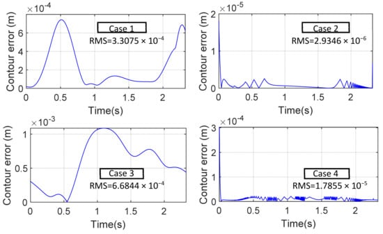
Figure 6.
The position contour errors for the 4 simulation cases.
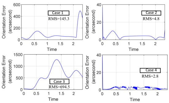
Figure 7.
The orientation errors for the 4 simulation cases.
5. Experimental Results
The proposed contouring controller was also employed in the YCM NXV560A five-axis machine tool to experimentally validate its effectiveness. For the experiment, a conical workpiece was machined by side milling, as shown in Figure 8, where the sizes of the workpiece are indicated. Figure 9 shows a snapshot during the machining and Figure 10 is the finished product. For this experiment, the tool center point needs to follow a circular path having a diameter of 80 mm. The circular path can be described by the intersection of a sphere and a plane, which forms the first two equivalent contour errors. The tool orientation vector is again pointed to a fixed point denoted by (, ,, similar to the simulation cases. Thus, the third and fourth equivalent contour errors are the same as in Equation (8). Therefore, the equivalent errors for this path are given by:
where mm and and are constant coefficients. Again, (, , can be expressed as functions of the machine coordinates using the forward kinematics, Equation (1). For the desired commands, the S-type velocity profile along the circle was designed. The total motion time was planned to be 28 s.
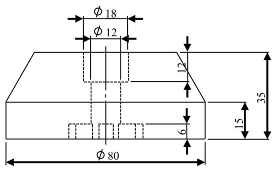
Figure 8.
The conical workpiece for machining.
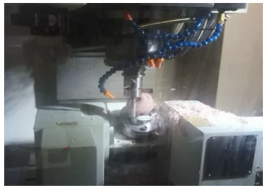
Figure 9.
A snapshot during the five-axis machining.
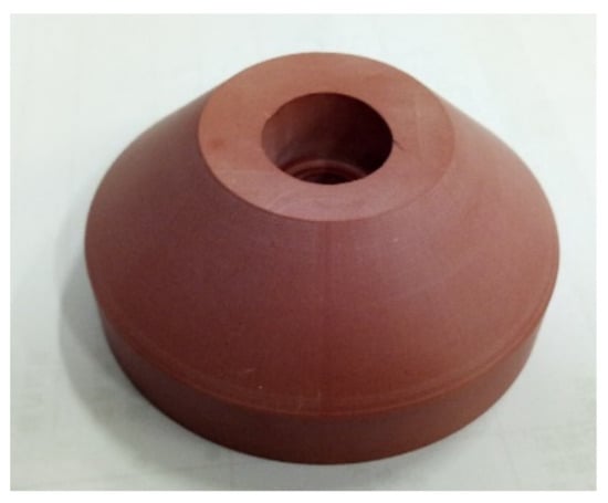
Figure 10.
The finished product.
The ISMC controller was used for the experiment with control gains (b1, b2, , µ) = (350, 114,000, 0.1, 0.05). The controller was implemented using dSPACE’s DS1103 motion control card for real-time control. The sampling time was set to 1 ms. The experimental results are shown in Figure 11 and Figure 12, where the position contour errors are shown in Figure 11 and the orientation errors are presented in Figure 12. The RMS position contour error is μm, and orientation error is ″. The results clearly verify the effectiveness of the proposed method.
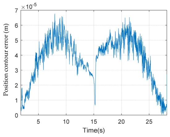
Figure 11.
Experimental results: the position contour errors.
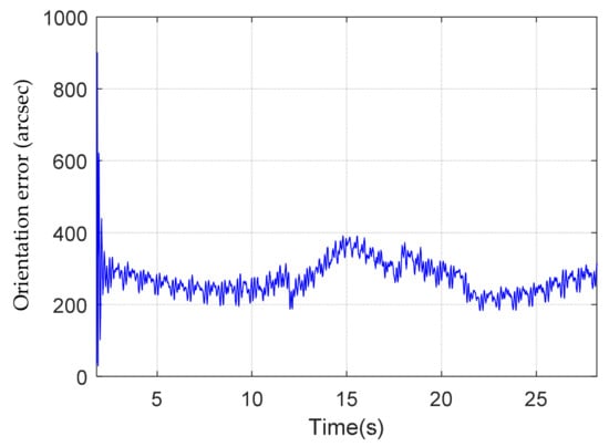
Figure 12.
Experimental results: the orientation errors.
6. Conclusions
The contouring control problem of five-axis machine tools was investigated in this study. The purpose was for the system to follow a given trajectory in the workpiece coordinate system with a specified tool orientation vector. Conventionally, to reduce both the position contour and orientation errors, the controller has been designed separately. However, the contour error and orientation error possess coupled dynamics. For better performance, the method of equivalent errors was applied in this study to design an integrated contouring controller. The trajectory with the tool vector in the workpiece coordinate frame was regarded as a 5-D hyper-curve in the machine coordinate frame. A contouring controller was designed to follow the 5-D hyper-curve by the method of equivalent errors. The proposed controller can simultaneously reduce both position contour error and orientation error. Numerical simulations for the contouring control of linear and circular paths were conducted. For comparison, the simulations with the conventional PD controller were also carried out for both linear and circular paths. It was found that the proposed controller can result in much better performance in either position contour error or orientation error, for both linear and circular paths. An experiment for a conical workpiece was also carried out. The experimental results clearly verify the effectiveness of the proposed method.
Author Contributions
Conceptualization, S.-L.C.; methodology, S.-L.C.; software, M.-H.K.; formal analysis, M.-H.K.; investigation, M.-H.K. and S.-M.H.; resources, S.-L.C.; data curation, M.-H.K. and S.-M.H.; writing—original draft preparation, M.-H.K.; writing—review and editing, S.-L.C.; visualization, M.-H.K. and S.-M.H.; supervision, S.-L.C.; project administration, S.-L.C.; funding acquisition, S.-L.C. All authors have read and agreed to the published version of the manuscript.
Funding
This research was funded by the Advanced Institute of Manufacturing with High-tech Innovations (AIM-HI) from The Featured Areas Research Center Program within the framework of the Higher Education Sprout Project and by Ministry of Science and Technology, Taiwan grant number MOST 110-2218-E-194-009, MOST 111-2218-E-194-005, and MOST 110-2634-F-194-005 And The APC was funded by MOST 111-2218-E-194-005.
Conflicts of Interest
The authors declare no conflict of interest.
References
- Xu, X.W.; Newman, S.T. Making cnc machine tools more open, interoperable and intelligent—A review of the technologies. Comput. Ind. 2006, 57, 141–152. [Google Scholar] [CrossRef]
- Koren, Y. Control of machine tools. Trans. Am. Soc. Mech. Eng. J. Manuf. Sci. Eng. 1997, 119, 749–755. [Google Scholar] [CrossRef][Green Version]
- Koren, Y. Cross-coupled biaxial computer control for manufacturing systems. J. Dyn. Syst. Meas. Control 1980, 102, 265–272. [Google Scholar] [CrossRef]
- Koren, Y.; Lo, C.-C. Variable-gain cross-coupling controller for contouring. CIRP Ann. 1991, 40, 371–374. [Google Scholar] [CrossRef]
- Chen, S.L.; Liu, H.L.; Ting, S.C. Contouring Control of Biaxial Systems Based on Polar Coordinates. IEEE/ASME Trans. Mechatron. 2002, 7, 329–345. [Google Scholar] [CrossRef]
- Huo, F.; Poo, A.-N. Improving contouring accuracy by using generalized cross-coupled control. Int. J. Mach. Tools Manuf. 2012, 63, 49–57. [Google Scholar] [CrossRef]
- Chiu, G.-C.; Tomizuka, M. Contouring control of machine tool feed drive systems: A task coordinate frame approach. IEEE Trans. Control. Syst. Technol. 2001, 9, 130–139. [Google Scholar] [CrossRef]
- Sarachik, P.; Ragazzini, J. A 2-dimensional feedback control system. Trans. Am. Inst. Electr. Eng. Part II Appl. Ind. 1957, 76, 55–61. [Google Scholar] [CrossRef]
- Yeh, S.-S.; Hsu, P.-L. Theory and applications of the robust crosscoupled control design. In Proceedings of the 1997 American Control Conference (Cat. No. 97CH36041), Albuquerque, NM, USA, 4–6 June 1997; Volume 1, pp. 791–795. [Google Scholar]
- Yeh, S.S.; Hsu, P.L. Estimation of the contouring error vector for the cross-coupled control design. IEEE/ASME Trans. Mechatron. 2002, 7, 44–51. [Google Scholar]
- Chiu, G.T.; Yao, B. Adaptive robust contour tracking of machine tool feed drive systems—A task coordinate frame approach. In Proceedings of the 1997 American Control Conference (Cat. No. 97CH36041), Albuquerque, NM, USA, 4–6 June 1997; Volume 5, pp. 2731–2735. [Google Scholar]
- Sencer, B.; Altintas, Y.; Croft, E. Modeling and control of contouring errors for five-axis machine tools—Part I: Modeling. J. Manuf. Sci. Eng. 2009, 131, 031006. [Google Scholar] [CrossRef]
- Sencer, B.; Altintas, Y. Modeling and control of contouring errors for five-axis machine tools—Part II: Precision contour controller design. J. Manuf. Sci. Eng. 2009, 131, 031006. [Google Scholar] [CrossRef]
- Chen, S.-L.; Wu, K.-C. Contouring control of smooth paths for multiaxis motion systems based on equivalent errors. IEEE Trans. Control. Syst. Technol. 2007, 15, 1151–1158. [Google Scholar] [CrossRef]
- Shyh-Leh, C.; Chang-Yan, C. Contouring Control of Robot Manipulators Based on Equivalent Errors. Asian J. Control. 2014, 16, 904–914. [Google Scholar]
- Lu, T.-C.; Chen, S.-L. Genetic-algorithm-based S-curve Acceleration and Deceleration for Five-axis Machine Tools. Int. J. Adv. Manuf. Technol. 2016, 87, 219–232. [Google Scholar] [CrossRef]
- Mercorelli, P.A. Theoretical Dynamical Noninteracting Model for General Manipulation Systems Using Axiomatic Geometric Structures. Axioms 2022, 11, 309. [Google Scholar] [CrossRef]
- Mercorelli, P. Robust decoupling through algebraic output feedback in manipulation systems. Kybernetika 2010, 46, 850–869. [Google Scholar]
- Lu, T.-C.; Chen, S.-L.; Yang, E.C.-Y. Near Time-optimal S-curve Velocity Planning for Multiple Line Segments under Axis Constraints. IEEE Trans. Ind. Electron. 2018, 65, 9582–9592. [Google Scholar] [CrossRef]
- Kornmaneesang, W.; Chen, S.-L. Time-optimal Feedrate Scheduling with Actuator Constraints for 5-axis Machining. Int. J. Adv. Manuf. Technol. 2022, 119, 6789–6807. [Google Scholar] [CrossRef]
- Chen, S.-L.; Chou, C.-Y. Contouring Control of Multi-axis Motion Systems for NURBS Paths. IEEE Trans. Autom. Sci. Eng. 2016, 13, 1062–1071. [Google Scholar] [CrossRef]
- Chen, S.-L.; Tsai, Y.-C. Contouring Control for Multi-axis Motion Systems with Holonomic Constraints: Theory and Application to a Parallel System. Asian J. Control. 2016, 18, 888–898. [Google Scholar] [CrossRef]
- Kornmaneesang, W.; Chen, S.-L.; Boonto, S. Contouring Control of an Innovative Manufacturing System Based on Dual-arm Robot. IEEE Trans. Autom. Sci. Eng. 2022, 19, 2042–2053. [Google Scholar] [CrossRef]
- Khalil, H.K. Nonlinear Systems, 2nd ed.; Prentice Hall: Hoboken, NJ, USA, 1996. [Google Scholar]
Publisher’s Note: MDPI stays neutral with regard to jurisdictional claims in published maps and institutional affiliations. |
© 2022 by the authors. Licensee MDPI, Basel, Switzerland. This article is an open access article distributed under the terms and conditions of the Creative Commons Attribution (CC BY) license (https://creativecommons.org/licenses/by/4.0/).