Review

Hardware-in-the-Loop Simulations: A Historical Overview of Engineering Challenges

Faculty of Electrical Engineering and Computer Science, University of Maribor, Koroška Cesta 46, SI-2000 Maribor, Slovenia
*
Author to whom correspondence should be addressed.
These authors contributed equally to this work.
Electronics 2022, 11(15), 2462; https://doi.org/10.3390/electronics11152462
Submission received: 1 July 2022 / Revised: 30 July 2022 / Accepted: 3 August 2022 / Published: 8 August 2022

Abstract

:
The design of modern industrial products is further improved through the hardware-in-the-loop (HIL) simulation. Realistic simulation is enabled by the closed loop between the hardware under test (HUT) and real-time simulation. Such a system involves a field programmable gate array (FPGA) and digital signal processor (DSP). An HIL model can bypass serious damage to the real object, reduce debugging cost, and, finally, reduce the comprehensive effort during the testing. This paper provides a historical overview of HIL simulations through different engineering challenges, i.e., within automotive, power electronics systems, and different industrial drives. Various platforms, such as National Instruments, dSPACE, Typhoon HIL, or MATLAB Simulink Real-Time toolboxes and Speedgoat hardware systems, offer a powerful tool for efficient and successful investigations in different fields. Therefore, HIL simulation practice must begin already during the university’s education process to prepare the students for professional engagements in the industry, which was also verified experimentally at the end of the paper.

1. Introduction

During the system development process, using parts or complete hardware in the simulation loops is very important for the so-called hardware-in-the-loop (HIL) simulations. The real hardware (when available) is used in the simulation loop instead of strenuous and long-term testing of the control algorithms [1,2]. At the same time, HIL simulation also includes controller-in-the-loop (CIL) simulations, forming the backbone of the automotive, defense, marine, and space industries. This simulation is infallible in testing a component, such as an electronic control unit (ECU), and is connected to the simulation instead of the real equipment under control. The fact is that the actuators are hard to model, and, when they are available, can be incorporated into the simulation loop to improve the simulation.
Usually, the testing of the system and then its evaluation are run in real time. The control input is provided within the desired sampled period in such an embedded system. It is important to point out that the control signal is crucial for the stability of the system. HIL simulation as a tool for testing the control system has been present for the longest time in the aerospace industry: here, the software for flight control systems could be a safety critical issue, and the combination of all these aspects has encouraged its use in the following:
  • Intense pressure to reduce development cycles;
  • Safety requirements which require exhaustive testing of a control system before using on the real plant;
  • The need to prevent costly failures, either in-service or late in the design cycle;
  • Reduced cost and greater availability of off-the-shelf products for HIL simulation.
In the last half-century, HIL simulation has played an essential role in the field of flight simulation [3]. At the same time, broad use of this method can also be found in the testing of missile guidance systems [4]. Even before this, highly maneuverable aircraft technology (HiMAT) was developed by NASA [5]. Within this program, the use of advanced concepts was investigated (such as fly-by-wire and reduced static stability). Additional to NASA’s development of an area of high-fidelity HIL simulations, the USAF Phillips Lab has developed a laboratory to integrate component technologies and demonstrate spacecraft subsystem/payload level capabilities [6].
HIL simulation is developing fast from a system model design, synthesis, and simulation criterion. An HIL simulator is often a powerful tool in many applications, such as airplanes, missiles, and uncrewed aerial- or ground-traffic vehicles, where the autopilots play a crucial and vital role [7]. Through the HIL simulator, the embedded system is forced to operate in real time, such as in the real world with real inputs and outputs. For example, the autopilot fools the aircraft system into thinking that it is flying. Figure 1a shows a general block scheme of an embedded system where an HIL simulator is used for testing, while Figure 1b shows the necessary components of a simple HIL simulator.
Like Gomez in [7] already reported more than 20 years ago, giving monetary judgments about the HIL simulators is tough and ungrateful. Unfortunately, there is almost no off-the-shelf HIL simulator for sale, although a couple of products and providers can come close. For example (according to [7]), if the first self-designed simulator in the mid-1990s cost slightly over EUR 100,000 (with 100 inputs and outputs), then the second identical unit cost about EUR 25,000 to build. This was considered a bargain compared to the multi-million dollar unmanned aerial vehicles (UAVs) they were developing—if the HILS prevented the crash of just one UAV, the company would get its money’s worth. There was another, even more, valuable benefit: a HILS allows the software to be developed and tested without waiting for the actual hardware to be built (or, in this case, built and flown).
In recent years, we have faced very complex power electronic systems, electric drives, and their control. Their use is growing significantly in distributed power generation, such as home and industrial electronics, traction, automotive, hybrid vehicles, aerospace systems, and the marine industry. Based on the significant progress in the field of power semiconductors, and various platforms, such as microcontrollers, microcomputers, and microprocessors, field programmable gate array (FPGA), and digital signal processor (DSP), we are witnessing high-performance electric drives [8]. Advanced software tools, such as MATLAB/Simulink [9] and real-time simulators [10], are used broadly in many engineering fields, i.e., education, research groups, and industry. The involvement of real-time simulations in modern engineering ensures an excellent aid for academia and researchers. It is, however, also very beneficial to have the HIL simulation become a part of the control development toolset [11].

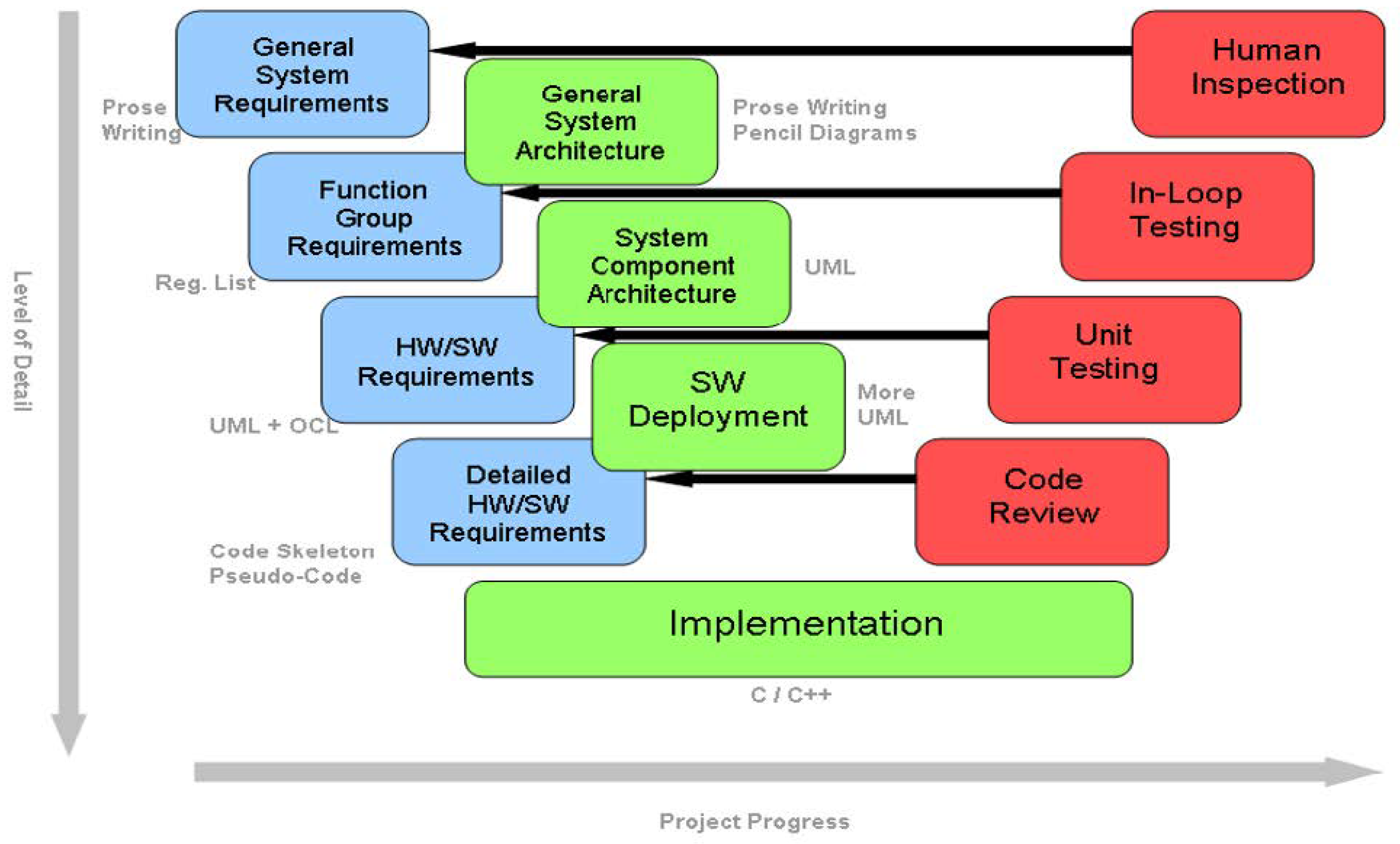
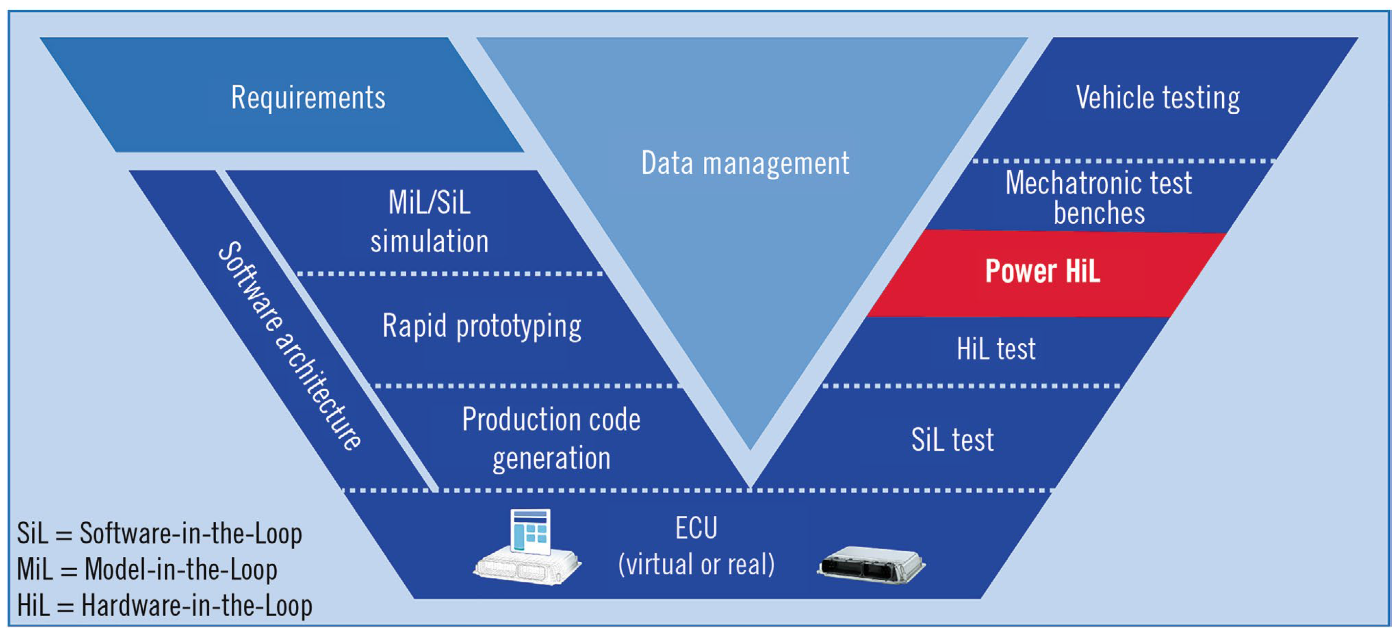
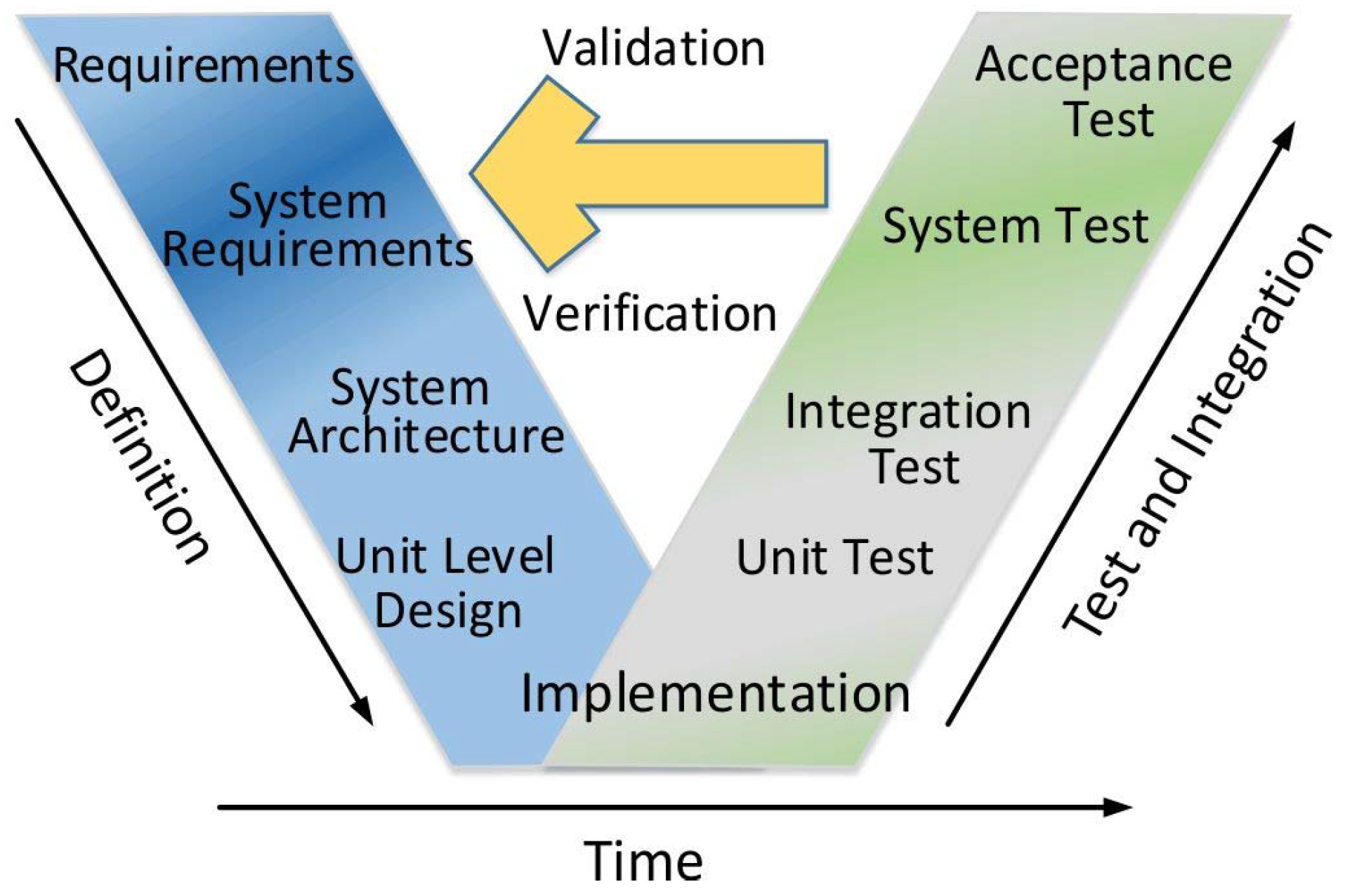
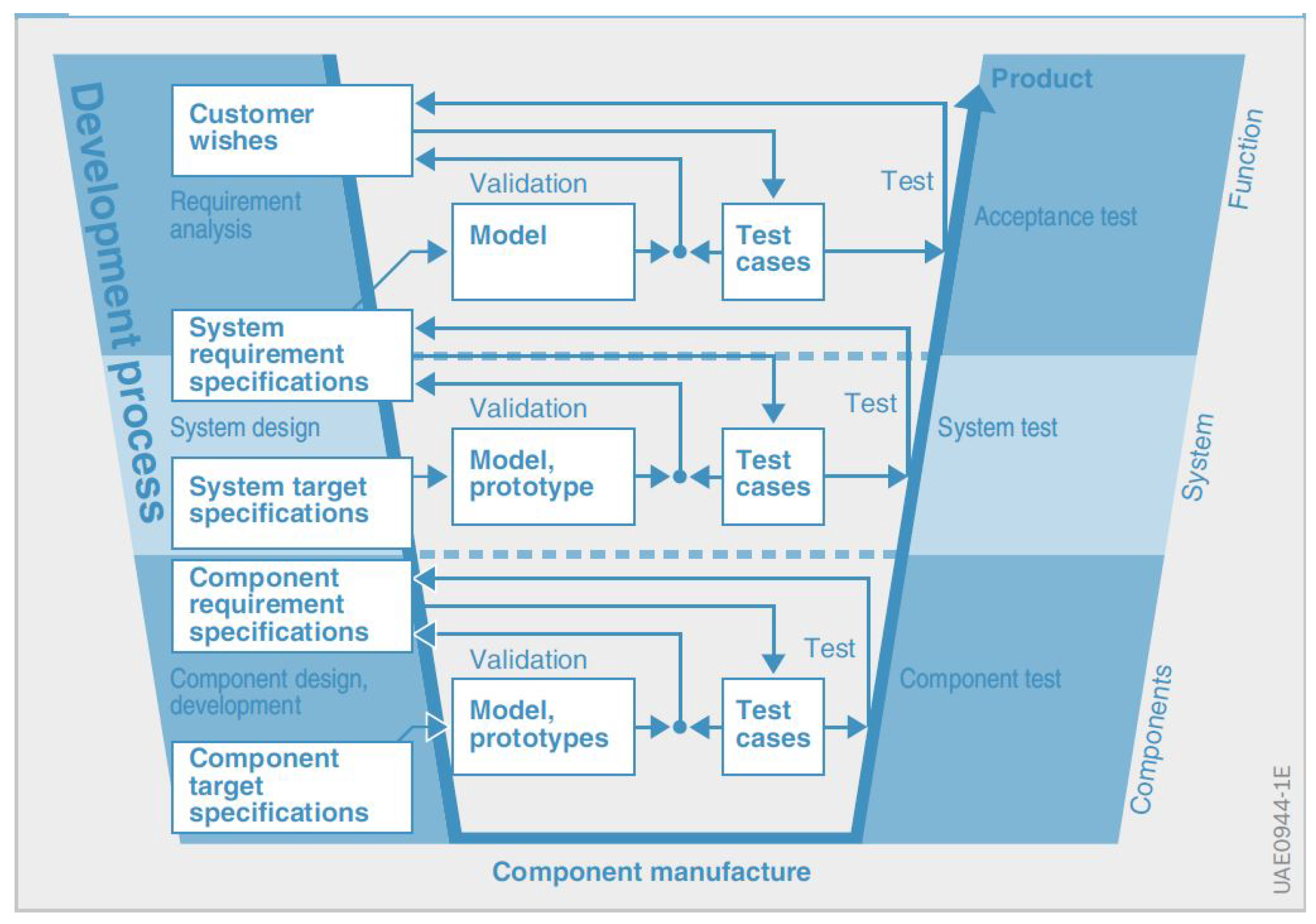
V-Models for the Development Procedures and Functional Safety

The development of medical equipment also requires comprehensive and careful testing procedures as a critical step against validation and successful certification. A new embedded deep brain recording system is reported in [12]. Real-time communication is running during the signal analysis in this rigorous environment. The considered HIL testing system is built on a single board DSP computer (SBC) with high performance, generating numerous analog signals. The development process is shown in Figure 2, where the integrated requirements are on the left side of the typical V model and the corresponding test methods are on the right side. While the requirements are in the blue color, the implementation of them is in green, and the red color on the right side is reserved for the test methods. A standard Ethernet interface is used for communication; the control interface is written using Java, and is not dependent on the computer’s platform.
In the automotive industry of the modern era, electric mobility is a significant trend, where power electronics are the main component. Through sophisticated power electronics systems with embedded control, the supplying voltage is transformed to the necessary AC or DC voltages. In [13], dSpace offers safe testing through the power hardware-in-the-loop (Power HIL or PHIL) systems, where a relevant emulation is used for the simulated signals (Figure 3) to validate the ECUs with software-in-the-loop (SIL) in HIL environments. The ECU software is, in a SIL solution, certified in a virtual environment. The ECU software can then be approved with no ECU hardware at all. The requested object model and the software run on a PC using particular tools. The test execution is also possible in the cloud with included scaling as well.
A design methodology (called functional safety) is accepted widely in all significant fields of industry to avoid the undesirable risk of physical injury or damage to people’s health. The human aspect plays an essential function during the development of hardware and software, making it practically impossible to be error-free [14]. The growing complexity of modern power electronics systems demands strong electrical safety requirements and tests of all components in road vehicles. However, it must assure strong functional safety performance as well. A basic standard relevant to most fields of the industry is dealing with functional safety [15]. However, different industry domains require typical requirements; therefore, supplemental standards are needed for functional safety. A functional safety standard for vehicles in the automotive industry is IEC/ISO 26262 [16]. On the contrary, in aerospace, there are two standards: DO-178/ED-12 for software certification requirements [17], and DO-254/ED-80 for the electronic hardware [18]. More precisely, the DO-178/ED-12 and DO-254/ED-80 are not, in fact, standards, but the relevant authorities, the Federal Aviation Administration (FAA) and European Aviation Safety Agency (EASA), treat them as de facto standards.
Figure 4 shows the functional safety V-model development process, which begins with the product’s requirements’ collection and presents the foundation for standards. The system’s architecture follows these requirements. The system is divided into separate units for their development. The implementation is enabled by writing the software (coding) and hardware design. Next, the testing of each unit as an autonomous system or software follows. The integration tests are provided for verifying the units’ joint operations. The system test follows this step, combining all units into the entire system or product. Finally, for a successful functional safety development process, the validation of the designed system is concluded with an acceptance test to comply with the requirements.
While different industries need specific standard requirements, some parallels are always possible: Figure 5 shows primary analogies for automotive and aerospace. In addition to the terminology, the documents, processes, and methods are different. However, the documentation can be reused for transferring between the fields. Nevertheless, the guidelines must be considered and followed during the whole process, particularly in aerospace, where suitable authorities, such as EASA and FAA, must be included in the project within the initiation phase.
To summarize, in the case of safety-critical applications in the industry, functional safety and HIL simulation are the most significant methods for reliable production. The following text will discuss the historical overview of different HIL simulation fields through particular examples within the automotive industry [19,20,21,22,23,24,25,26,27,28,29,30,31,32,33,34,35,36], electric drive control [37,38,39,40], power electronics converters [41,42,43,44,45,46,47,48,49], electric grid applications [50,51,52,53,54,55,56,57,58,59], railway traction systems [60,61,62], and education [63,64,65,66]. For that purpose, one master thesis within our research group was provided in this study year [66], dealing with the HIL simulations, including CIL for the automotive industry. In conclusion, the importance will be emphasized of different HIL simulation techniques for all fast-growing branches of industry.

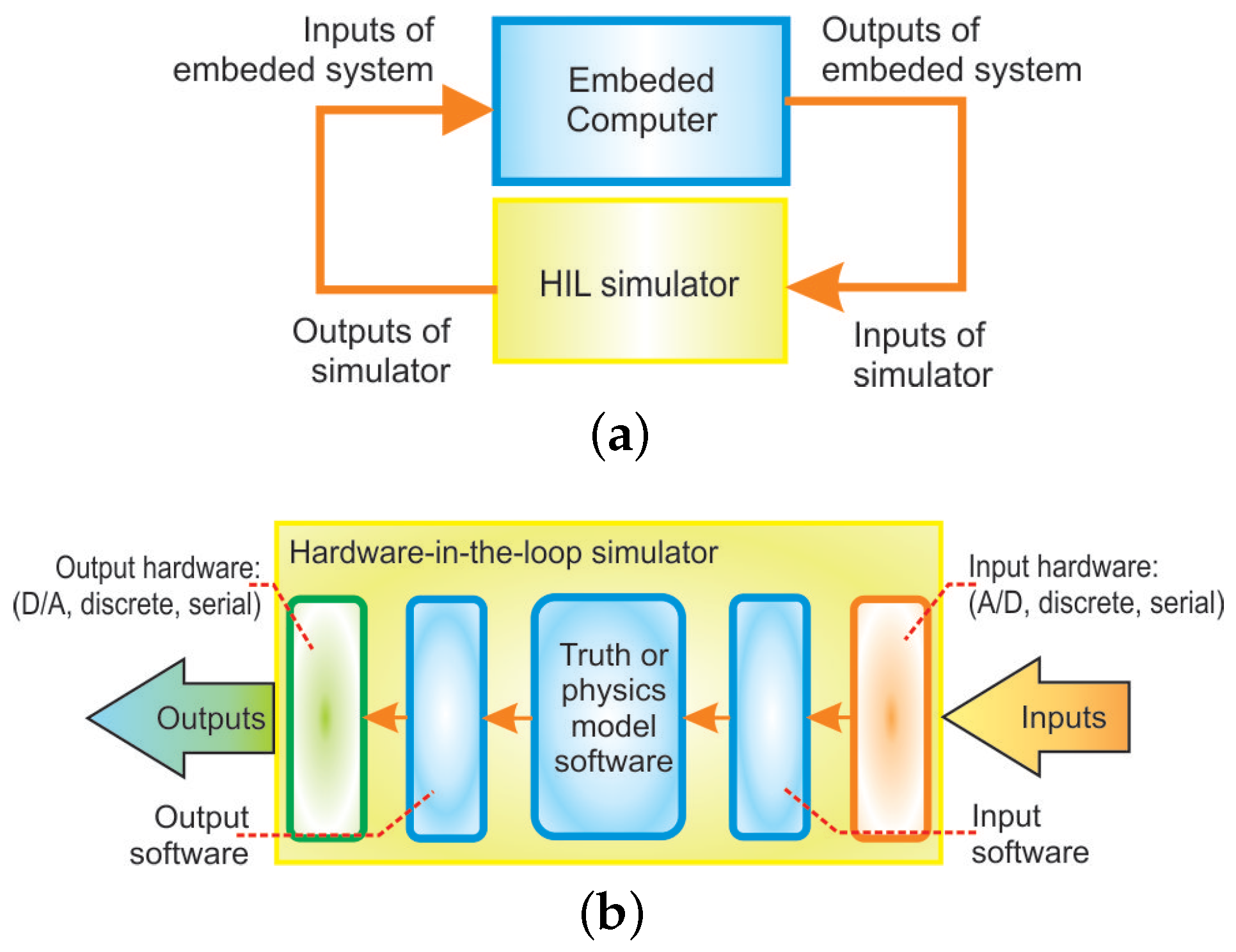
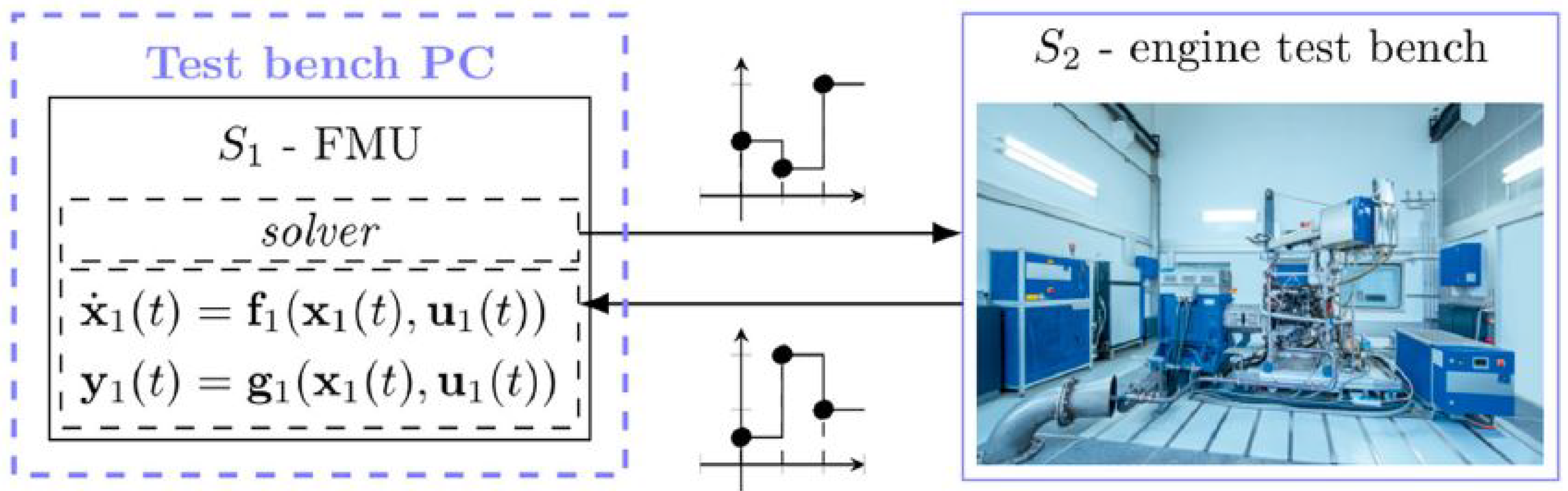
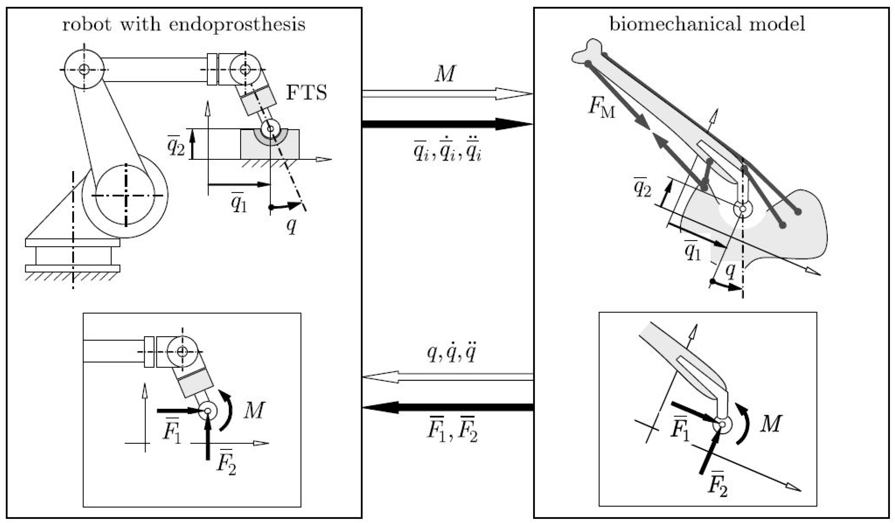
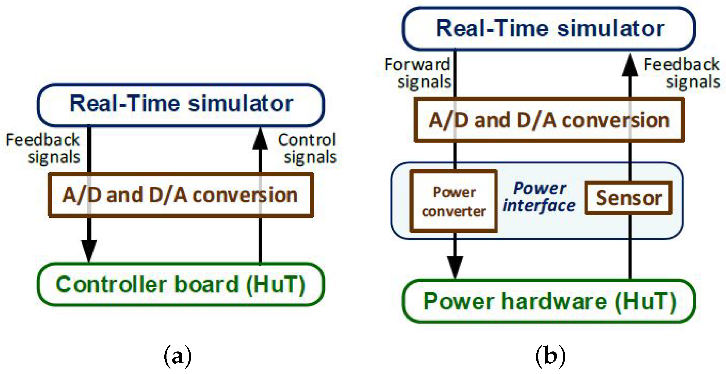
2. Hardware-in-the-Loop Simulation: Principles and Fields of Interest

A brief overview of the critical factors and applications of HIL simulation is given in the first section, with a focus on its transformation from a control validation tool into a system development conception. In the literature, there are various definitions of HIL simulation, some of which will be discussed here. Furthermore, Fathy in [23] defines a HIL simulator as “a setup that emulates a system by immersing faithful physical replicas of some of its subsystems within a closed-loop virtual simulation of the remaining subsystems”. This definition emphasizes an essential characteristic of the HIL simulator: the bidirectional interactions (with closed-loop) must be included between its physical and virtual ingredients. It is often also possible to assume unidirectional interactions between a given simulation structure’s virtual and physical parts with a slight fidelity loss. For example, when simulating the response of a virtual building to physically measured earthquake signatures, the building’s influence on the earthquake origins can be neglected (see Figure 6a). Furthermore, it is possible to neglect the influence of the chassis’s vertical motion on the road profile when simulating the response of a physically prototyped car chassis to a virtual road profile (see Figure 6b). In both considered cases, this leads to a driving subsystem that can be simulated or measured offline, and a guided subsystem that can be simulated using the outputs of the driving subsystem. Instead of realizing such decoupled simulators, we are faced with the challenge of designing a closed-loop HIL simulator, as shown in Figure 6c.

2.1. HIL Simulation in the Automotive Area

A controller’s estimation using HIL simulation has been in practice for many years. Since flight control systems are considered safety critical, this technique has been used in aerospace from the beginning [1,6]. The HIL methodology produces comprehensive control system testing for preventing damageable and costly failures. Moreover, HIL simulations reduce the time of development, and can enable more tests than are available on the real system.
Since the 1990s, numerous research and development (RD) groups in the automotive industry have employed HIL simulation for testing embedded ECUs [11,19]. With certainty, intensive and complex integration tests on the real vehicle can be bypassed by using this method. Therefore, the development time can be reduced significantly, and high quality can be assured. Indeed, in the automotive industry, HIL simulation is becoming a de facto standard for ECU development.
The integration of digital control systems characterizes the development of many modern products and processes. HIL simulation is required strongly during the design, testing of control systems, and implementation, where some control-loop components are real hardware, and some are simulated [20]. The controlled process consists of actuators, physical processes and sensors, which can then be simulated either fully or partially (see Figure 7).
A single, or several electronic load emulation (ELE) parallel-connected modules are coupled with the power control unit’s interface. The real-time models control each particular model (e.g., the real-time battery model replaces the physical battery, and the real-time electric motor model replaces the motor). Now, the voltages and currents are generated by the ELE modules, and calculated in the models directly at the terminals of the motor and the battery (see Figure 8). Finally, the resulting system offers improved testing for lower prices than standard mechanical testing, short development times, upgraded safety concerning LV 123 [67], and ISO 21498 standards [68].

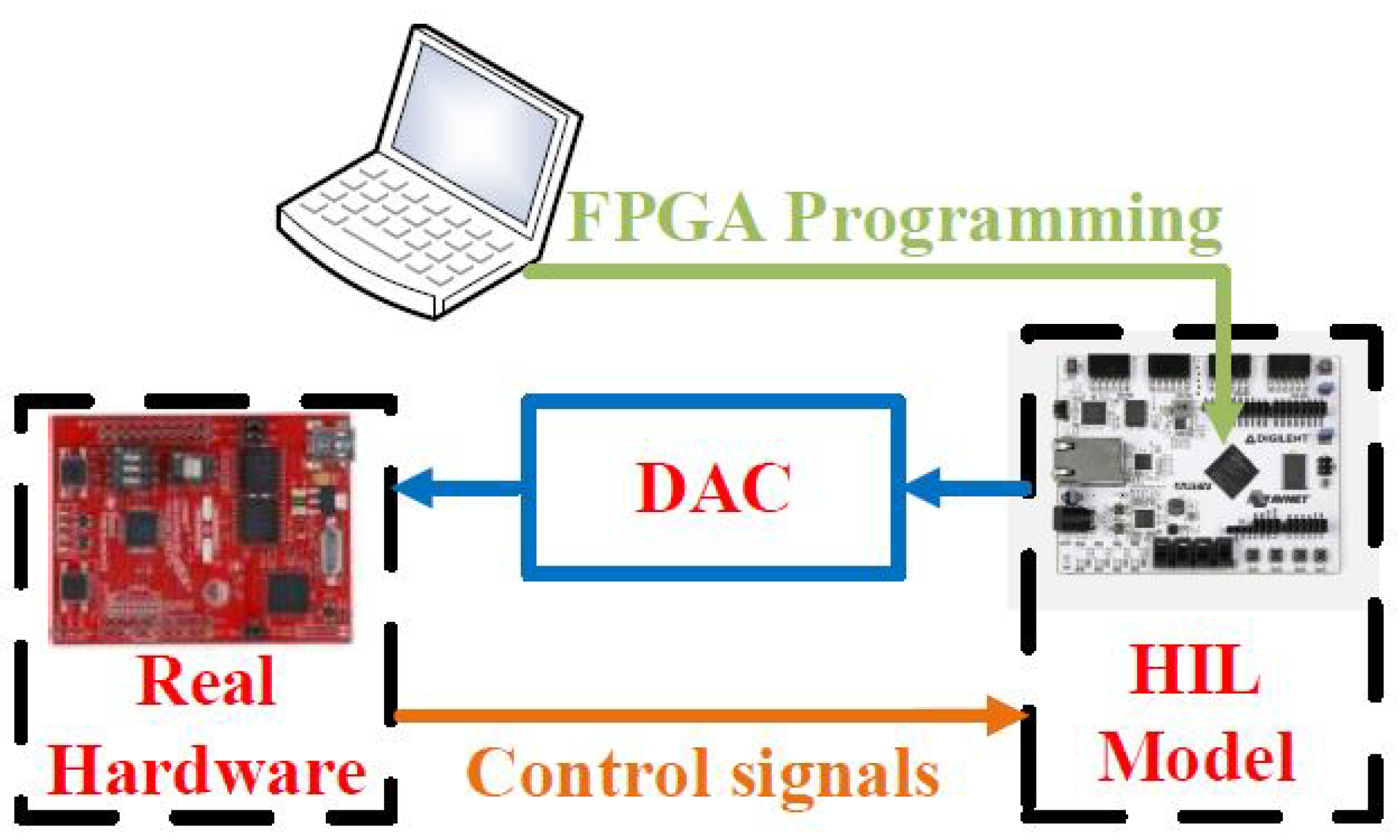
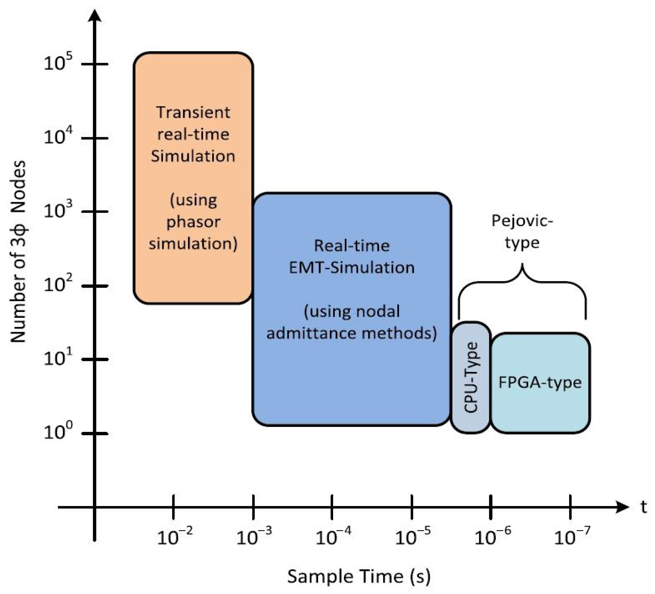
2.1.1. Real-Time HILTesting with FPGA Acceleration

HIL testing is a real-time simulation that enables the testing of the embedded code without the real system hardware. The system can be tested for abnormal and faulty conditions, which could damage the hardware. Validating embedded code for prototypes presents a challenge, due to the risk of hardware damage preventing the system from being tested across a complete range. Real-time execution is the key benefit of the system when using hardware in the loop testing. Specific issues make running a real-time model challenging and depend on the minimum step time. For higher dynamics systems, such as power electronics, where the real-time step is at the level of microseconds, there is no referral as to whether the CPU of FPGA is better for the simulation of the systems with switching dynamics. When choosing the proper combination, it is beneficial to use both CPUs and FPGAs in HIL testing, where desktop simulation is processed by multiple cores executed on FPGAs. Vendors such as dSpace use paths to accelerate real-time execution by creating a desktop simulation model that can be converted to HDL to be run on FPGA, and thereby program the real-time machine by bitstream. The level of integration between simulation tools and FPGA tools, in this case, Xilinx Vivado, depends merely on the HIL system design, where the FPGA tools are incorporated in the system design and not accessed directly. Xilinx FPGA is also used in Matlabs Speedgoat. Other vendors, such as Typhoon HIL, use custom FPGA solvers.

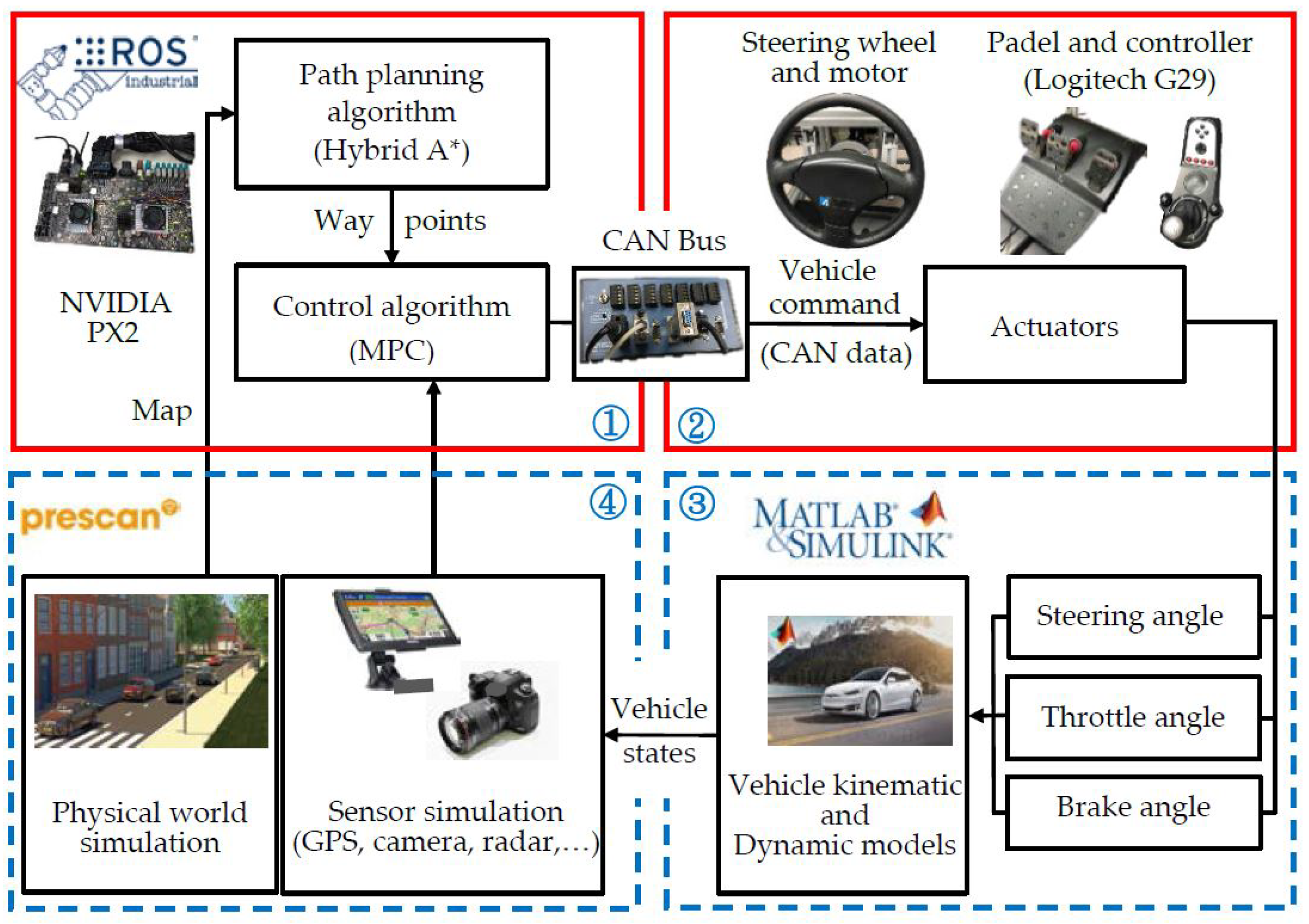
2.1.2. Automotive and HIL Simulation Examples

In developing a power-train system, simulation engineers usually simulate the dynamics of the engine in a closed loop with a simulated control unit. Eventually, they conduct a HIL simulation of the simulated engine dynamics in a closed loop with the real ECU. The inaccuracy problem in the established simulations is discussed in [21]. The problems are essential to the techniques currently available to simulate event-based systems, that is, the time-consuming variable-step algorithms. Such inaccurate conventional fixed step algorithms can be solved using the novel MATLAB/Simulink toolbox RT-Events Blockset for system modeling and the RT-LAB environment for distributed simulation. The compensation for the events during the sampling time is the fundamental idea behind the RT-Events library of blocks. By using this new toolbox with the RT-Event Blockset, modeling and simulating the internal combustion (IC) V-6 engine system adequately is possible.
Additionally, in the late 1990s, one novel HIL scale vehicle testbed, called the Illinois roadway simulator (IRS), was used for studying control and vehicle dynamics [22]. An overview of the system and particular hardware issues is presented here. By using scaled vehicles, verification was made between vehicle responses of full-scale and scaled-down vehicles in the ratio of 1:10. In the end, the IRS was used to examine the effect of actuator dynamics on a particular vehicle control application.
The use of HIL simulation for the system-level experimental evaluation of powertrain interactions and development of strategies for clean and efficient propulsion as a state-of-the-art engine-in-the-loop (EIL) simulation structure is discussed in [23]. This structure includes a real diesel engine connected to an accurate real-time driver, driveline, and vehicle models, through a highly responsive dynamometer. Different conventional and hybrid powertrains enable both performance and fuel economy prediction verification. Additionally, the facility can replicate the highly dynamic interactions occurring within a real powertrain, and measure their influence on transient emissions and visual signature through advanced instruments. The viability of this structure for integrated powertrain system development is illustrated through a case study exploring the development of advanced high mobility multipurpose wheeled vehicle (HMMWV) powertrains.
Distributed embedded automotive control systems play an essential function in current automotive design, and there is an urgent demand to investigate the impact of different design decisions on reliability and safety [24,25]. In the modern passenger vehicle, dozens of ECUs are connected to various sensors, actuators, and units, to assure high-level functionality and services. An appropriately detailed HIL simulation is a highly effective method to perform the testing for such an investigation. A novel HIL testbed has been developed for this goal in the Embedded Systems Laboratory at the University of Leicester (see Figure 9) [25]. Detailed descriptions of the vehicle and engaged driver models are presented in the designed simulator. Finally, the system’s performance is demonstrated through an example that is based on an adaptive route control.
In [26], a high accuracy, cost-effective, and experimental HIL steer-by-wire test setting is described, which offers an outline of the real-time steering simulator. A nonlinear tracking controller is implemented in the haptic interface, to guarantee that the steering mechanism follows the operator’s commands. At the same time, the driver receives a tunable force feedback. Improved steering functionality with the variable-geometry suspension-based steering control system is performed by HIL simulation in [27].
When development investments for integration, validation and testing of new electric powertrains should be reduced, the development assignments must be moved to earlier phases of the project. Special HIL procedures for electric traction machines were designed at the RWTH Aachen University for this purpose [28]. The traction machine is tested via a load machine within that test bench setup. The DC-supplied inverter is connected to the traction machine. A dSpace Autobox control module communicates via Gigalink with a dSpace real-time Scalexio simulator [69]. The Scalexio simulator performs the test bench control at a sample rate of 1 ms, with control algorithms for the load machine, the traction machine, and the DC supply. Simultaneously, the electrical, mechanical, and thermal measurements are conducted by the FEV Europe GmbH Aachen automation system, and transmitted to the Scalexio simulator via a deterministic EtherCAT communication module (Figure 10).
Recently, the European Union (EU) lawmaking introduced rules about emission restrictions for light-duty vehicles, making the economy the main challenge for automotive engineers. An IPG CarMaker hybrid vehicle model is reported in [29], which includes a designed dual-clutch transmission system. The hybrid drivetrain model is connected to the test system with an IC engine by a real-time HIL simulation. The electric powertrain is virtual, and defined in the application (Figure 11a). Figure 11b shows the experimental test setup, equipped with a ZSG416, 4-cylinder engine with a capacity of 1600 cm3. Three different gear changing strategies were used to keep the physical characteristics of the drivetrain unchanged. At the end of the driving cycle, the fuel economy of the hybrid electric vehicle was improved by 15.75% with the same electric current consumption.
In developing the automotive ECU, exact simulation models of the ECU sensors and actuators are required for HIL simulation. By using the MATLAB SimMechanics Toolbox (now Simscape Multibody [70]), a complete dynamic mathematical model of an automotive windshield wiper system is developed and validated in [30], following the classic V-model for product development from [19] (Figure 12).
The tightened demand for more efficient vehicles requires strict energy consumption regulations strongly for improved fuel economy and reduced emissions as a response to the growing deficiency of natural resources and global environmental problems. Regardless of whether the vehicles are entirely battery electric (BEV), full-hybrid electric (HEVs), or plug-in hybrid electric (PHEVs), batteries always play the most critical and central role. Lithium-ion batteries are preferred in automotive applications because of several outstanding characteristics, such as rapid charging time, low self-discharge rate, high-energy density, and efficient power output, which benefit their use in automotive applications. In the HEVs, the lithium-ion batteries’ state of charge (SOC) is estimated and validated experimentally by the HIL, as reported in [31]. The setup consists of a 1.25 kWh 48 V lithium-ion battery with a numerical model via an RC equivalent circuit with temperature dependence. Figure 13 presents the flowchart of the proposed approach. The SOC of the battery is estimated by artificial neural networks (ANNs) in real-time with a 2% accuracy.
Road forces on the tire are provided to the steering wheel through an equivalent torque for an improved driving feeling in the driver’s hands. The HIL approach analyzes and validates the effect of the steering electrical torque feedback in the vehicle’s handling [32]. A dynamic car model with a 14-degree-of-freedom (DOF) is then simulated, including tires, the engine, and the steering system mechanism. The primary advantage of the 14-DOF model against other simpler models (e.g., three- and seven-DOF models) is that it is formed of full six-DOF models for the damping system dynamics and the body of the vehicle. The 14-DOF model of the damping system is presented in Figure 14. A damper and a spring are between each wheel’s body and suspension arm. The final results confirm that the torque feedback enables the driver to handle the vehicle satisfactorily, improving their perception of the surrounding conditions.
Autonomous driving is becoming more popular, daily. In [33], a dynamic path planning and model predictive control (MPC) is applied to simulate parking and self-driving for an electric van on an HIL simulation control system. The hardware simulator system consists of a Nvidia drive PX2 with a robot operating system (ROS), electric power steering system, accelerator, and brake pedals. The HIL simulation control system for experiments contains two parts, as shown in Figure 15. First, the hardware part in the red quadrants 1 and 2 consists of a Nvidia AutoChauffeur PX2, a power steering wheel with a motor, an accelerator, and a controller (Logitech G29) for the brake pedal. Next, the software part is in the blue quadrants 3 and 4. Finally, an actual test was performed on this HIL simulation control system, to verify the feasibility of turning from manual to self-driving mode, dynamic route planning, obstacle avoidance, and auto-parking.

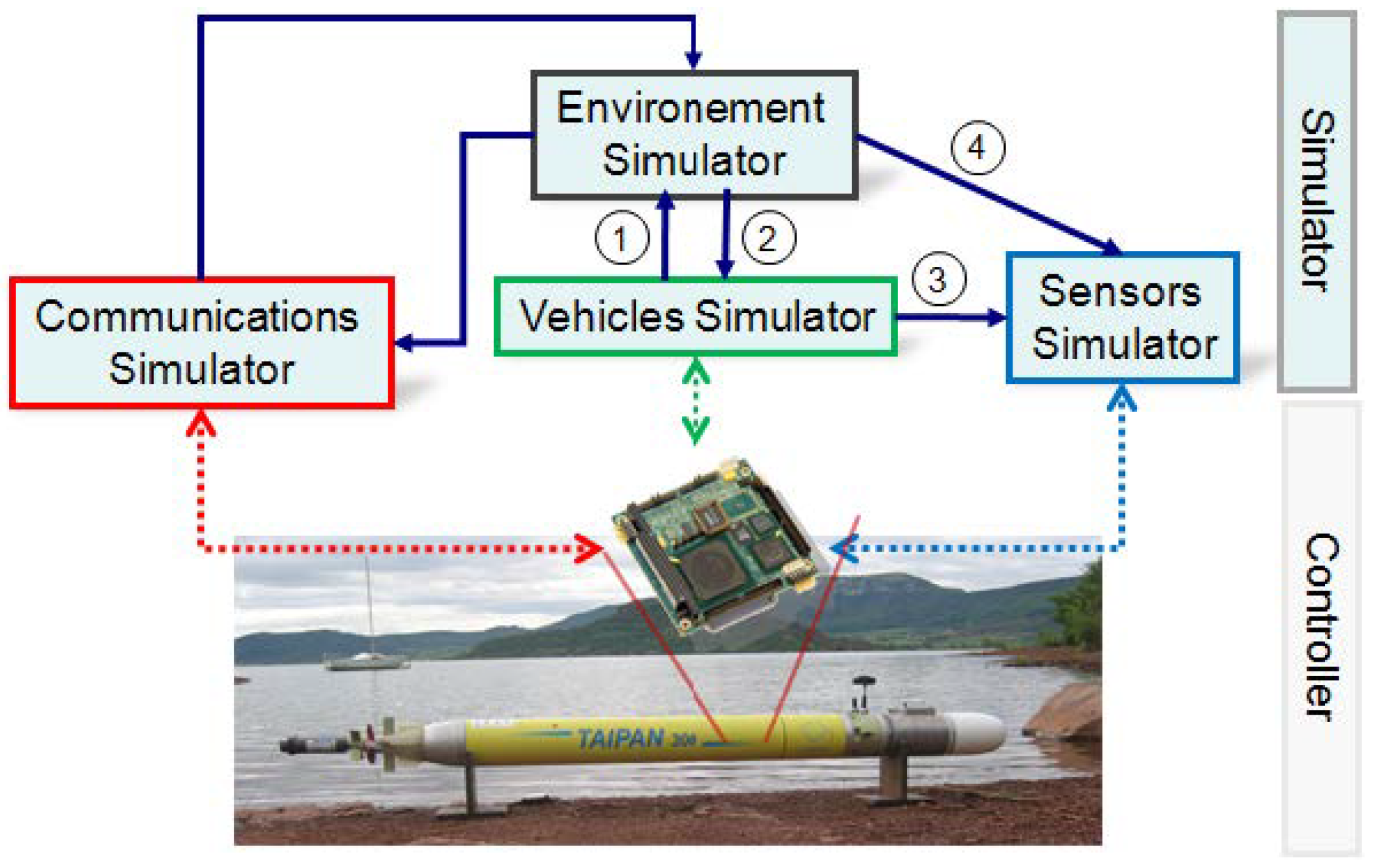
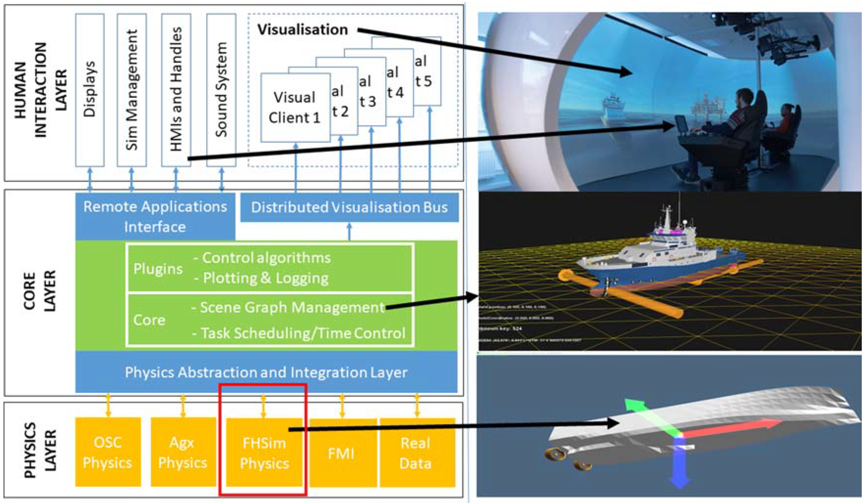
2.1.3. Marine Traffic and HIL Simulation Examples

A new HIL simulation structure is considered in [34] for a better overview of the available marine robotics simulators for multi-vehicle cooperation. A real-time multi-vehicles hybrid simulator (called Thetis ) with communication abilities for heterogeneous vehicles is presented in [35] (see Figure 16). It allows HIL simulations, including using virtual sensors to present a virtual world, and supports communication between the vehicles.
Abstract, or existing systems’ behavior, can be displayed through digital models or virtual prototypes (VPs). VPs are helpful in offshore operations in procedure planning, design, control system testing, proof of concept for new equipment or methods, and expert crew training. In addition, VPs can be used in full mission simulators with crews of maritime and offshore engineers, in which case they combine with control systems, such as handles and dynamic positioning systems. A creative framework for rapid VP of ships for hardware- and human-in-the-loop simulations is presented in [36]. The assembled data in a sea trial achieved on a research vessel validated the outcomes of precise positioning.
Figure 17 presents the modularity of modern simulation and co-simulation software, which can be analyzed in layered modules. Control commands and photo-realistic visualization are essential in the upper (or human interaction) layer. A middle (or core) layer synchronizes and connects all the modules. The lower (or physics) layer delivers the actual calculation data, such as the ship’s simulation engine FHSim in the red box (in Figure 17).

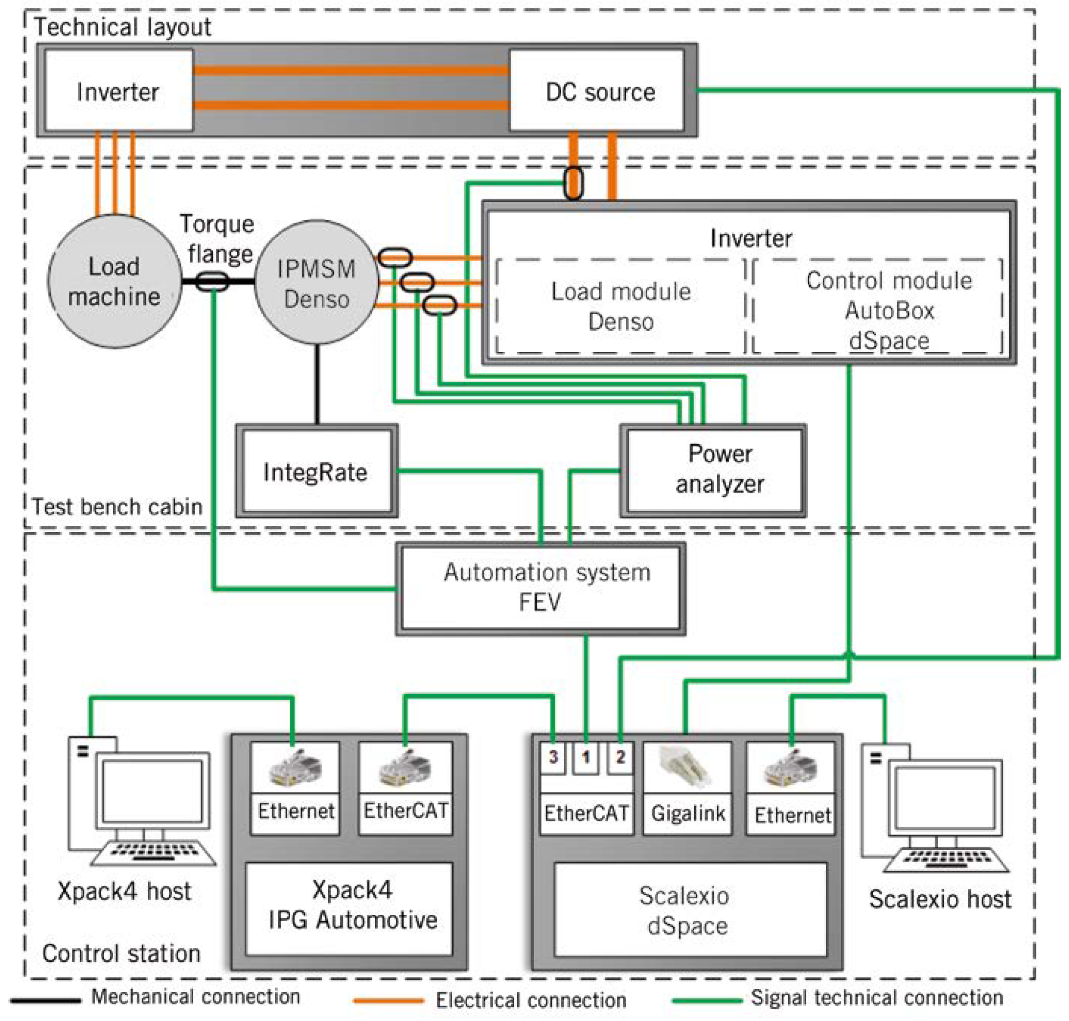
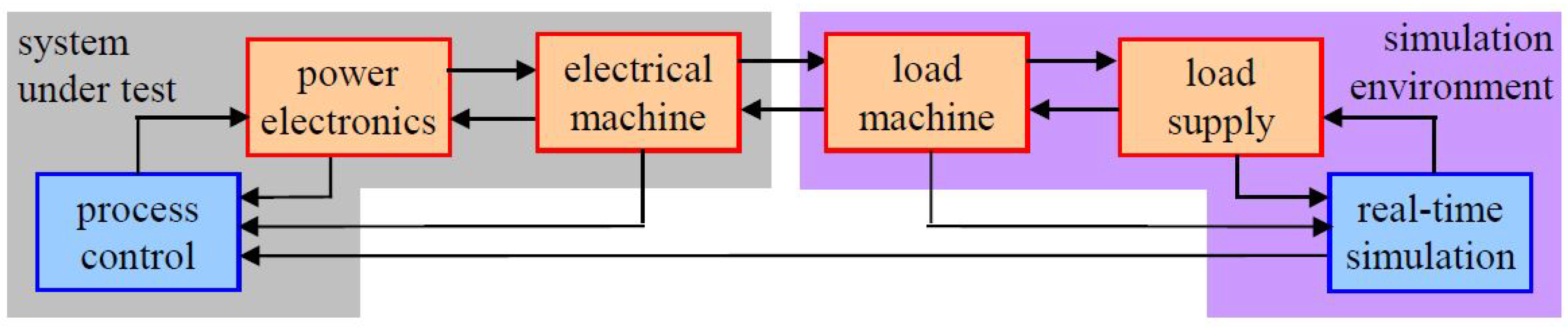
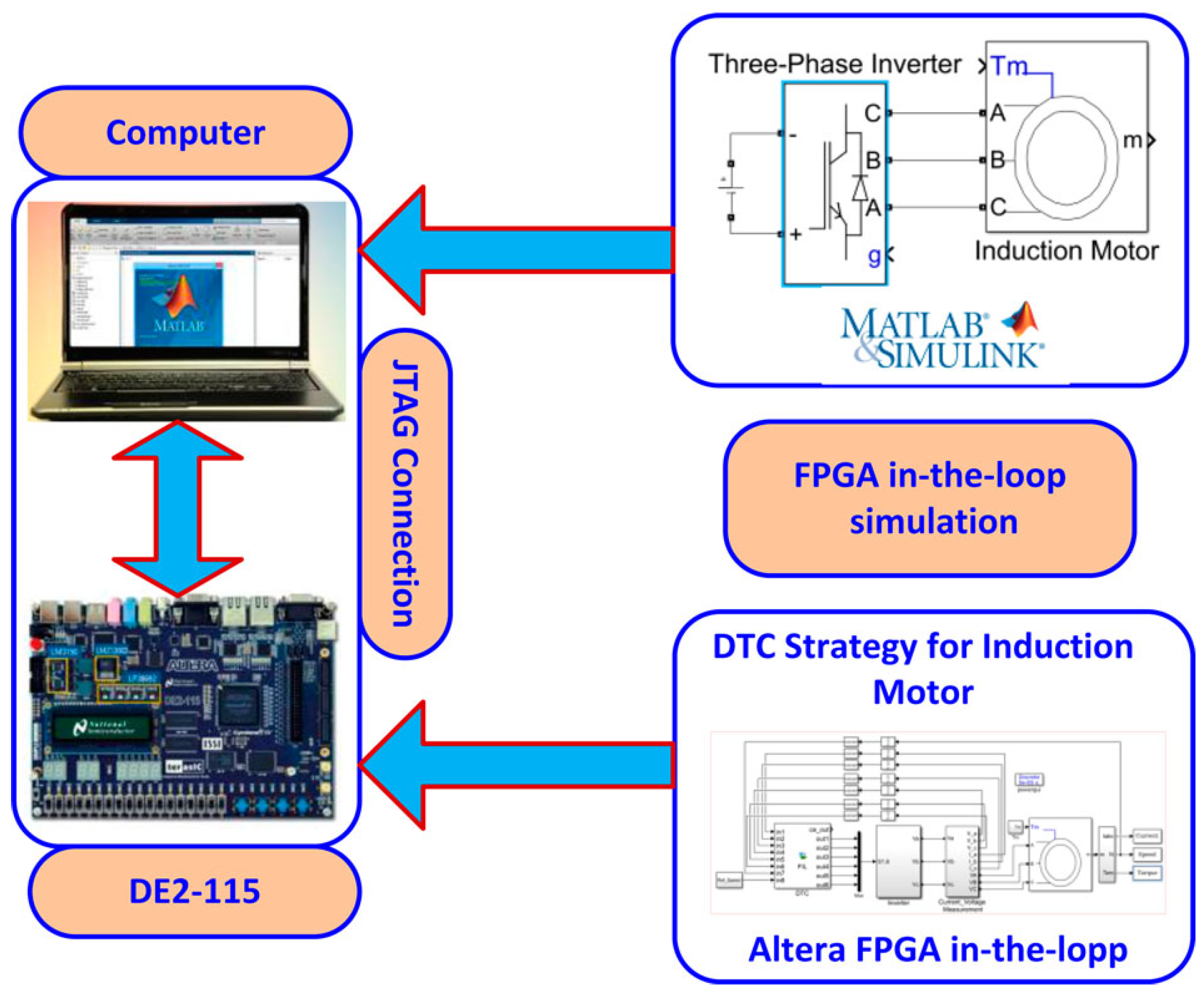
2.2. HIL Simulation in Electric Drives

In industrial applications, the use of electric drives is increasing. Simulations software is a dominant primary measure for achieving the needed performance of the drive and its control [37]. Simple models then replace the power system to determine and adjust the control algorithm. HIL simulations are welcome for validation tests before implementation on real processes. In HIL simulation, one or several real devices are used instead of their simulation models in the simulation software. The further parts of the process are simulated in parallel computers or on a controller board [1]. Multiple software simulation tools enable control system development in the studied case. The computation time can be reduced through many simplifications. Prior to a real-time implementation of the complete control and the system (e.g., vehicle, train, and grid), HIL simulations could be a practical and helpful intermediate step. In such a way, a hardware unit is introduced into the loop with its real restrictions. Based on [37], there are three types of HIL simulation: at the signal, power, and mechanical levels. The most important is the last one, with testing the complete drive (control, power electronics, and electric machine) and simulating the mechanical part (Figure 18).
Mechanical inputs and outputs are forced through the simulation system on the electrical test machine. Simultaneously, the controller unit under test receives measurements on the mechanical part. The additional electrical machine (or load machine) is a controlled electro-mechanical load supplied by a second power electronics set (or load supply). The second controller board (real-time simulation) is needed to control the load machine and send virtual mechanical “measurements” to the controller board under test. The interface between the simulation setting and the system under test corresponds to mechanical variables.
In modern industrial applications, high-performance alternating current (AC) drivers are designed and used extensively to control induction motors. They enable the control of the rotor position, motor speed, or torque in specific working fields. The scalar or vector control process is usually applied on AC drives. However, the scalar control method is preferable in applications that do not require high performance, because its implementation is low cost and simple [71]. Finally, the mechanical part measurements must be sent to the controller under test.
On the other hand, in the vector control method, the flux and torque of the motor are controlled independently of each other as in a direct current (DC) motor. However, the mathematical model of the induction motors has a complex structure with time-dependent parameters, including high-order and non-linear differential equations. Because of the complex structure, the control of an induction motor is more demanding than the control of a DC motor. The vector-controlled AC drives were first started by a study by the German engineer Blaschke in 1971 [72]. Since then, the vector control strategy has been the basis of high-performance AC drive systems, and has been researched thoroughly in many studies. Indeed, the direct torque control (DTC) and the field-oriented control (FOC) methods, both from the vector control methods, are used widely today.

Electric Drives and HIL Simulation Examples

In [38], the possibility of using the HIL simulation for considering the total energy residual (TER) was presented in [38]. The proposed approach was verified with the standard co-simulation (or distributed simulation), to demonstrate that TER can be used to compare non-iterative Jacobi and Gauss–Seidel co-simulation masters. An example with the defined global error demonstrates that the prescribed value of TER can determine the benefits of a specific co-simulation master correctly. An HIL simulation (Figure 19) introduces hardware into a co-simulation loop, and demands all slaves to run in real time. Finally, the experiments show that this approach assures the speed-controller parameters for the engine effectively.
The hysteresis-based DTC of a three-phase induction motor was performed experimentally in [39]. The DTC algorithm was modeled using a high-performance hardware environment, FPGA in-the-loop. The dSPACE DS1103 controller board was applied for the experimental part, and the hardware modeling was performed in the standard development board Altera DE2-115 (Figure 20). All DTC algorithms were tested within the FPGA platform with the same sampling time for both applications. The hardware simulation analysis in FPGA was run within the MATLAB/Simulink program. A comparison between the experimental results and the hardware simulation results received from the FPGA shows that the DTC algorithm could be provided quickly in an FPGA platform without experimental installation. Finally, the obtained voltage, current, and velocity waveforms were comparable.
An upgrade of the organized operation of several electrical drives with a sophisticated supervisory control system is integrated within any robot. For simulating constraint elements of mechanical systems like joints or bearings in their environment, Ref. [40] proposes an HIL simulator. The concept is based on two different kinds of coupling between the actual mechanical component and the numerical simulation process according to the contact element’s unconstrained and constrained spatial directions. According to Figure 21, with a high-payload robot, the six-dimensional HIL simulator was developed to test total hip endoprostheses under different dynamic load conditions. Off-the-shelf commercial implants can also be compared using the HIL simulator, concerning their dynamic way of behaving under reproducible circumstances. Due to the muscular and soft tissue structures’ uncertain parameters, the biomedical model of the anatomical habitat cannot be exact. The relative comparison of implants under physiological load conditions represents a basic jump beyond the existing joint endoprostheses testing.

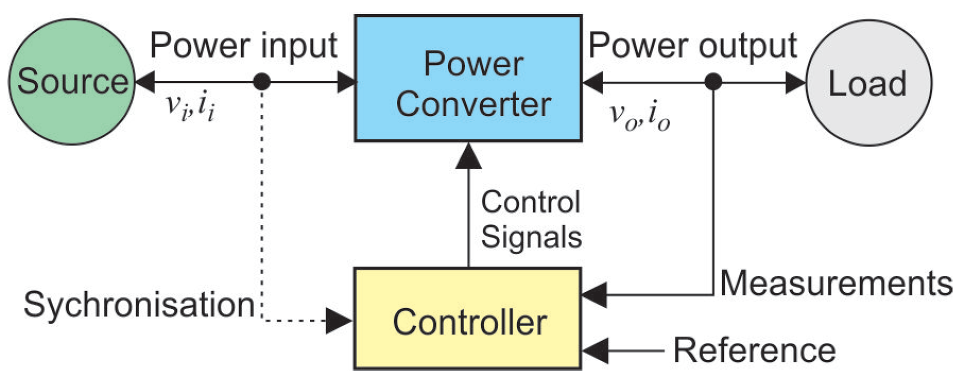
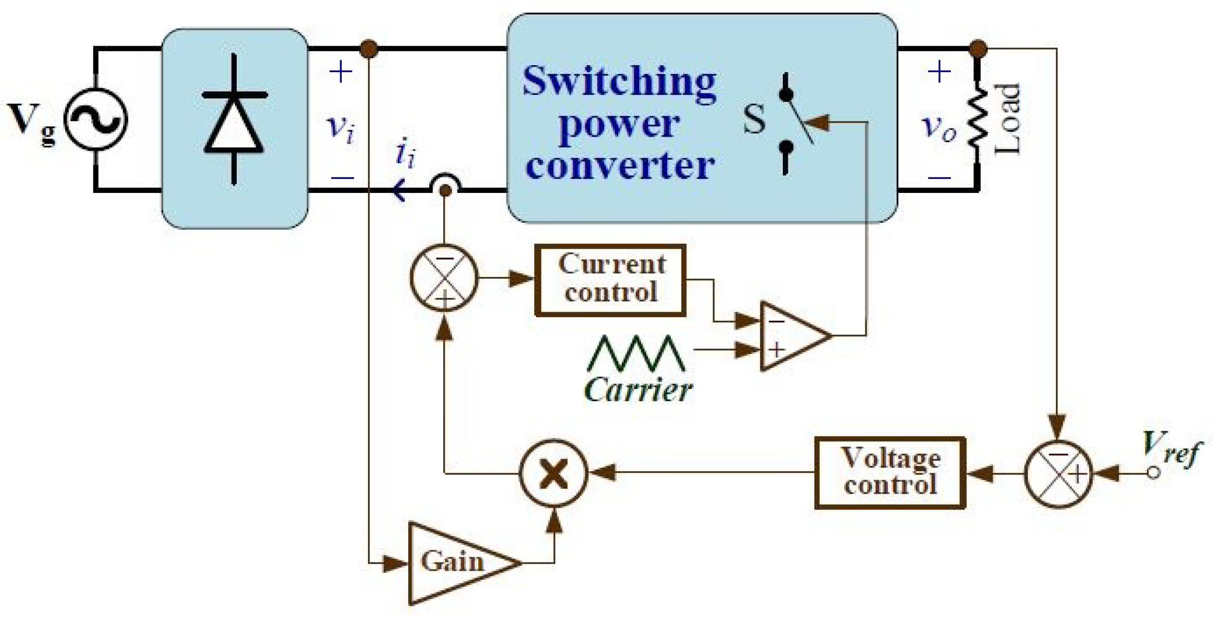
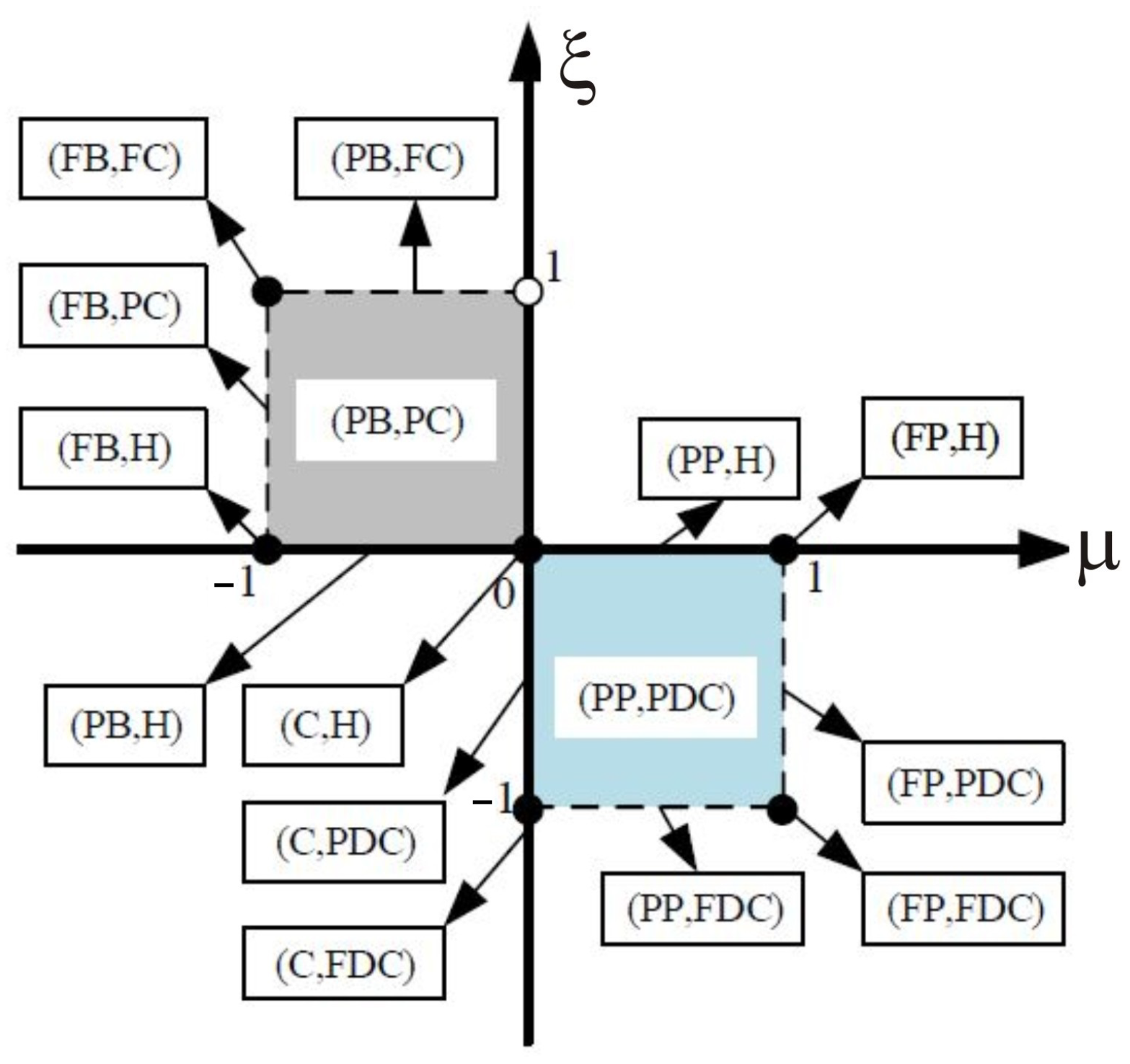
2.3. Power HIL Simulation for Power Electronics Converters

In general, the main task of power electronics converters is to process and control the flow of electric energy by supplying voltages and currents in a shape that is required by a load [73]. Figure 22 shows a power electronics system in a block diagram. The power input to the power converter system is usually single- or three phase from the grid at a line frequency of 50 or 60 Hz (but it could also be a photovoltaic, wind power generation, fuel-cell, or a battery in the automotive). The load requires the processed outputs (voltage, current, frequency, and the number of phases). A feedback controller compares the output of the power converter with the desired (or reference) values, and acts in a way to minimize the error. The power flow through such systems may also be reversible (in the case of active load, e.g., automotive or power factor correction (PFC) circuits), thus interchanging the input and output roles.
Applications of the HIL techniques for the simulation of switching-mode power supplies (SMPS) have been growing over the last 10 years due to the low cost of their safety. Furthermore, the outcome of HIL techniques has improved with incorporating DSPs and FPGAs, allowing faster and more accurate real-time simulations [41,42,43].

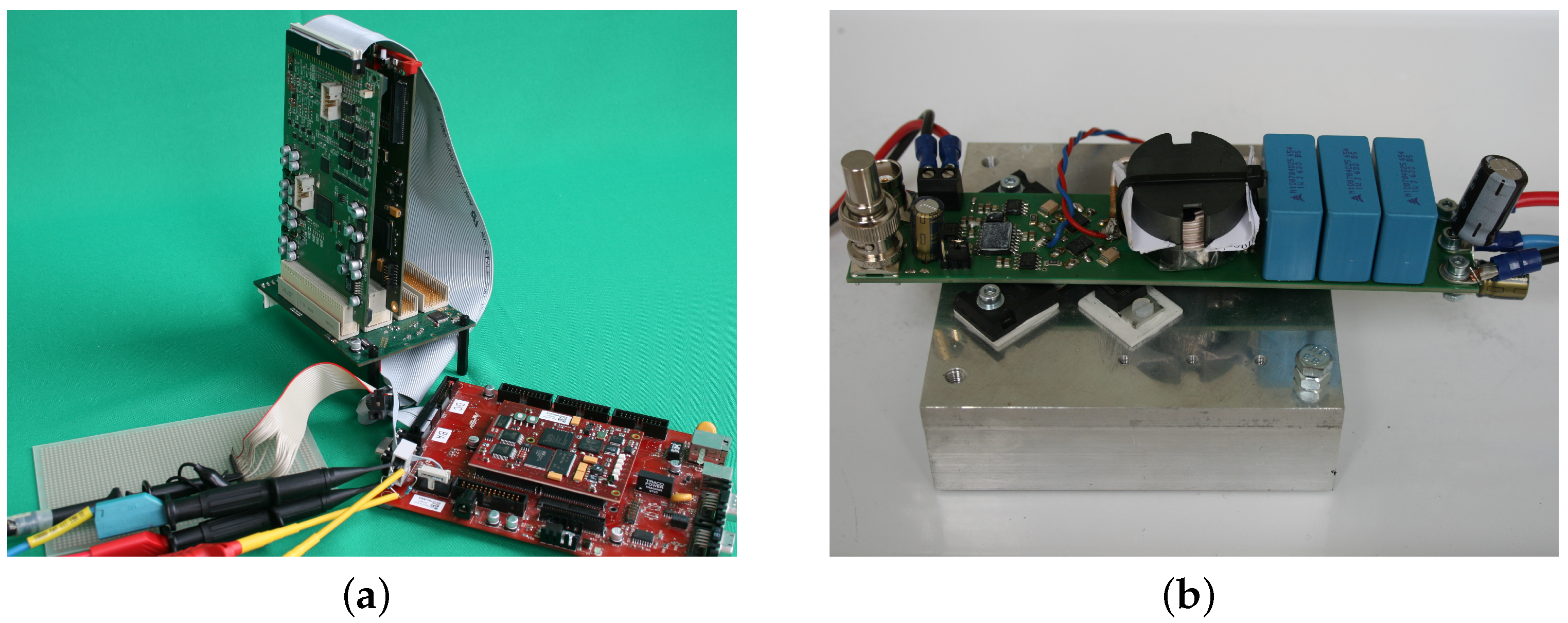
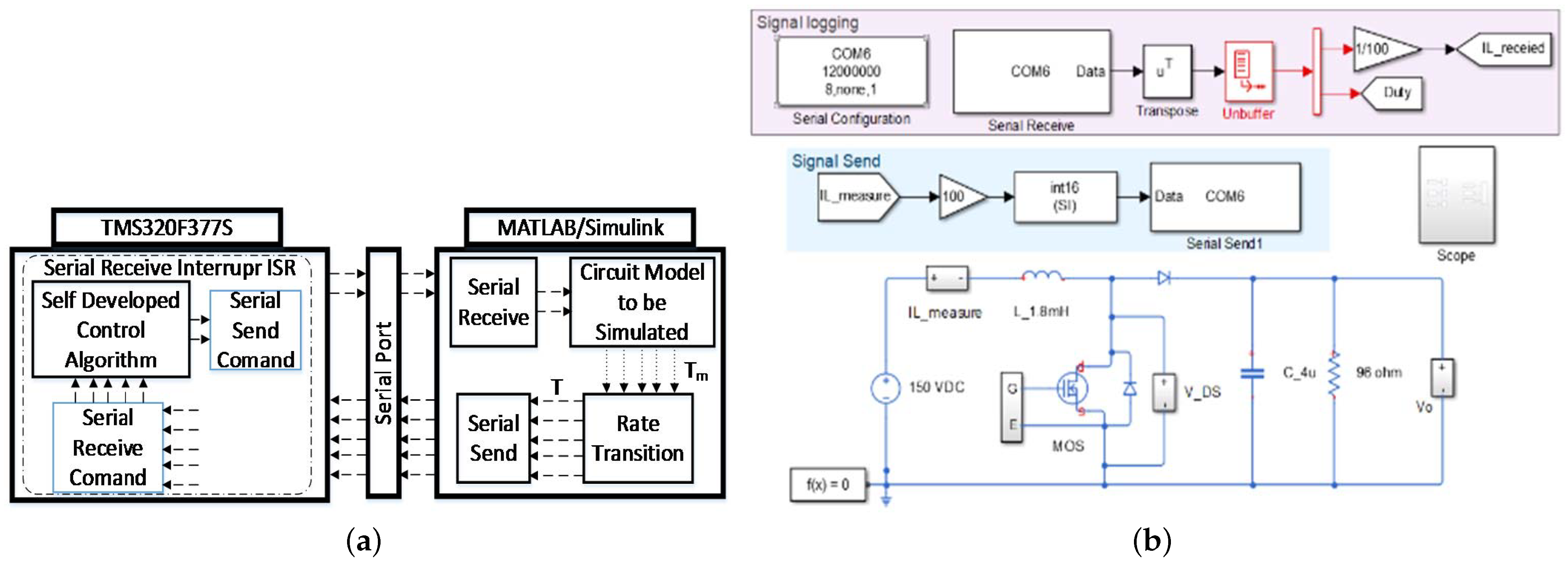
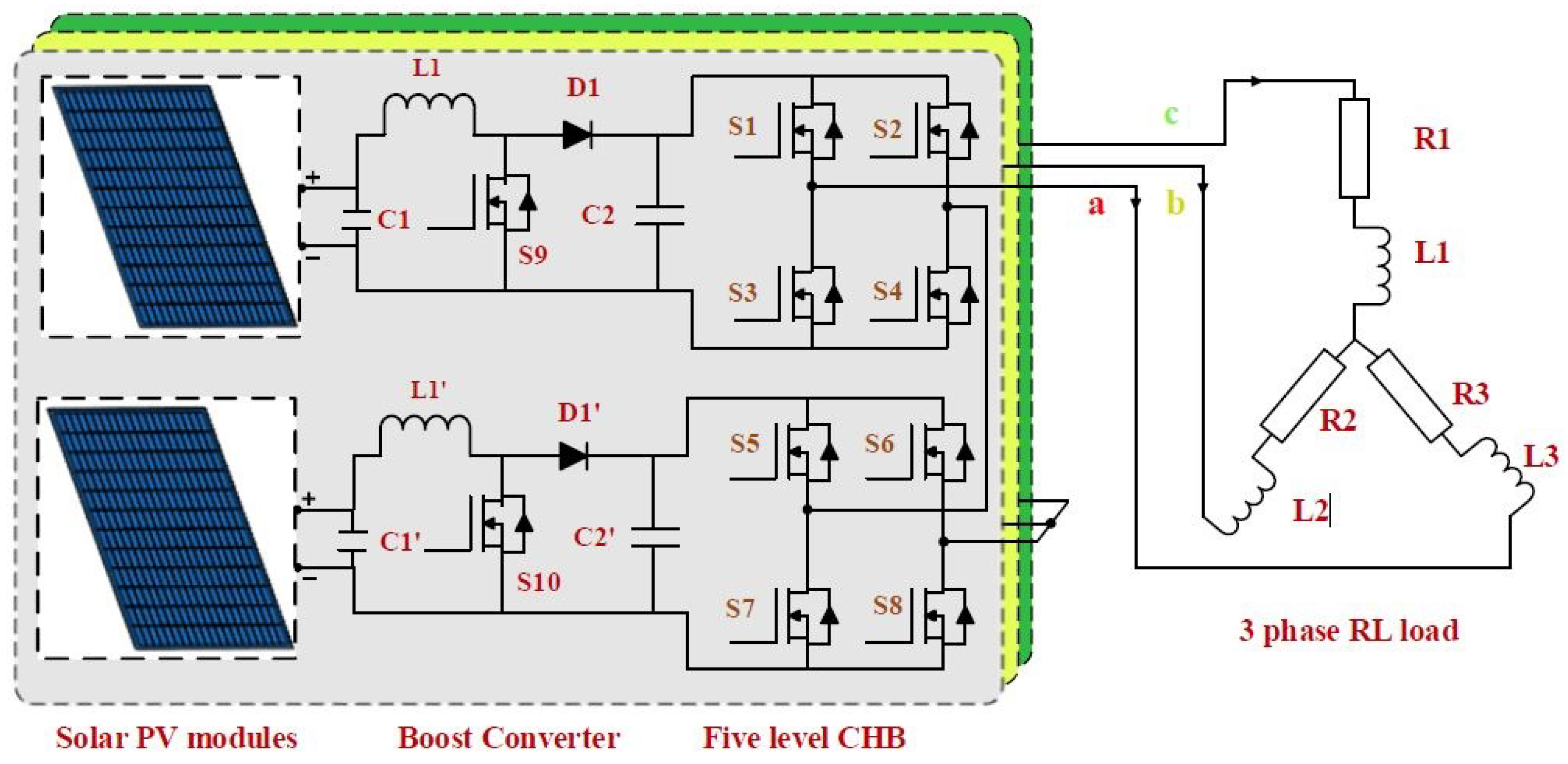
PE Converters and HIL Simulation Examples

Such a hardware platform is introduced through the modular design and open interfaces in [41] for a real-time simulation of a buck converter with a time-step of 1 μs without FPGA co-processing. The comparison is also provided between the obtained simulation results and the real hardware measurements (Figure 23). A description is presented of digital real-time simulation, including modeling and integration, a hardware platform for code execution, implementation of software, and hardware-in-the-loop testing.
In [42], the HIL performance of four popular numerical methods—1st order forward Euler, 2nd order Adams–Bashforth, 2nd order Runge–Kutta, and 4th order Runge–Kutta—were compared and evaluated through the best accuracy outcome. The topology under study was an asynchronous buck converter. All the considered methods were implemented in FPGA to simulate a simple power converter independently and as a part of the HIL system, including a DA converter. Then, the hardware synthesis results were obtained, with the minimum execution time for each method. The results show that even Runge–Kutta methods can achieve the best accuracy outcome. Once the accuracy limiting factors in real environments and the cost performance index (CPI) were considered, the simplest methods (1st order forward Euler and 2nd order Adams–Bashforth) achieved the best overall performance.
An implementation example of the communication process between the MATLAB/Simulink and digital signal processing unit during the simulation of the power converter control is presented in [44]. The application of the HIL is of great importance for the designer to estimate the effect of the digital signal processing unit on the controller response and system stability. In this application, a DC-DC boost converter operated as the maximum power point tracker, and the predicted current controller was implemented based on the perturb and observe algorithm of the photovoltaic system. The circuit of the boost converter was realized in the Simulink, while the entire control scheme was programmed on the digital signal processing unit. As shown in Figure 24a, the rate transition block was used to determine the operating frequency of the DSP board, since it can differ from the sampling frequency of the Simulink model. In this figure, T denotes the period of the data received from the controller output, and T m represents the sampling period of the MATLAB/Simulink model. As can be observed from the figure, two data are sent to the MATLAB/Simulink by the DSP and the five data are sent to the DSP by the MATLAB/Simulink during the experimental verification of the DC-DC boost converter control system. It was observed that there is a time delay of two sampling periods of MATLAB between the received data and transmitted data in the analysis of the boost converter. This delay is independent of the solver integration time step.
The DC to DC boost converter shown in Figure 24b is controlled by the pulse width modulation technique, and is used to track the maximum power point and to increase the PV output voltage. The boost converter parameters are designed to operate in the continuous current mode. Tracking of the maximum power point during the operation is obtained by the perturb and observe (P&O) method that is programmed in the DSP. The perturbation of the duty cycle generated by the DSP is used to test the cooperation of MATLAB and DSP. For the control and performance of the DC-DC converter during the transients (during the disturbance application on the duty cycle) the circuit’s dynamic model is used, derived using small-signal analysis [74].
In addition to the previous HIL simulations of basic DC-DC converters (i.e., buck and boost), investigation of the Ćuk converter is also provided through the HIL experiment. Several modeling methods for a fractional-order Ćuk converter operating in continuous conduction mode (CCM) are investigated in [45]. To establish the model, the state-space averaging method is used first. Based on the obtained model the transfer functions are derived, using the equations for the inductors’ current and capacitor voltage. Then, the dynamic model of the converter is obtained through application of the equivalent small parameter method. The Oustaloup filter principle [75] is used to construct the approximate models of fractional-order capacitors and inductors that consist of integer-order components, for the converter circuit model building purpose. The comparison of the different modeling method done through the presented simulation results shows that the equivalent small parameter method (ESPM) principle has some advantages over the other methods. Finally, the HIL experiment verified the effectiveness of the circuit model.
In [46], the authors compare different design alternatives for HIL emulation of two power converters in FPGAs (i.e., buck- and full-bridge converters; see the system in Figure 25). The various numerical formats (fixed and floating-point) and different approaches (pure VHSIC hardware description language (VHDL), automated MATLAB HDL code, high-level synthesis (HLS) and intellectual properties (IPs)) were proposed, to design power converters models. Despite the fact that the proposed models are simple power electronics HIL systems, the idea can be extended to any HIL system. The design efforts for different coding methods and numerical formats were evaluated through two synthesis tools (Precision and Vivado), and an analytical discussion was performed in terms of area and speed. The other models were synthesized as ad-hoc modules in general-purpose FPGAs. The NI myRIO device is an example of a commercial tool implementing HIL models. The comparison confirms that the application (frequency, complexity, etc.) and designers’ constraints, such as coding expertise, design effort and available area, determine the optimal design method.
A review of the state-of-the-art HIL techniques and digital control techniques for single-phase power electronic converters for PFC is given in [47]. The PFC approach plays a crucial role in single- and three-phase electrical power systems, enabling the control of output DC voltage while ensuring that the line current waveform complies with the prescribed grid standards. The verification of the single-phase power converter operation implies significant complexity and cost, since its behavior is tested through hundreds-of-milliseconds-long simulations. The control systems have to be tested in nominal, abnormal, and fault conditions, in which the equipment could be damaged. As already stated, the HIL simulation is a cost-effective technique that allows the power converter to be replaced by a real-time simulation model. So, the need to build prototypes is eliminated in the early stages for the development and validation of the controller. However, the performance vs. cost trade-off associated with HIL simulation depends crucially on the power system dynamic models. It is used for replicating the electrical grid, power converter, and the load, the hardware platform chosen to build it, e.g., the microprocessor or FPGA, and the required number of channels and I/O types to test the system.
As shown in Figure 26a, the HIL simulation system is called a controller hardware-in-the-loop (CHIL) when the actual control is part of the hardware model. In these systems, there is no real energy exchange since the energy system is emulated virtually. When energy transfer is involved in the simulation, the system is called PHIL (Figure 26b). Here, the internal emulation of the power system is in one part, while the rest of the system is realized as an externally connected real hardware power device. In this case, there is a need for an energy source (power supply) or energy sink.
Generally, there are two loops for the control in a PFC: near unity power factor operation is achieved by an internal fast current loop, and the output voltage is stabilized by an external slow voltage loop. In such a case, three variables are usually employed for the control purpose: input current and voltage and output voltage ( i i , v i and v o , see Figure 27), although control scheme proposals without a current sensor can be also found in the literature [76].
According to [77], based on the adopted current control techniques, the digital control of the PFCs can be classified into four groups:
  • Group I: Operation in discontinuous conduction mode (DCM) or at the boundary condition (BCM);
  • Group II: Linear control of the average current;
  • Group III: Non-linear carrier (NLC) control of the line current;
  • Group IV: Phasor-based control.
As known formally, in the Group II control approaches (shown in Figure 27), there are several widespread switching converters investigated and developed with the following advantages included:
  • Its bandwidth of the current acquisition stage is smaller than in the non-linear version.
  • The bidirectional PFCs (H-bridge converters) allow the energy recovery, but the non-linear control the non-stable operating conditions may be exhibited.
Ref. [49] focuses on the three-phase cascaded H-bridge (CHB) multi-level inverter (MLI) topology fed by the solar photovoltaic (PV) module. Solar PV is receiving extensive attention from investors and researchers worldwide. It is becoming the primary source of electrical energy generation among other non-conventional renewable sources, due to its low operating cost, low noise, high modularity, no rotating parts, and low maintenance [78].
To maintain the maximum power and constant voltage for MLI, the perturb and observe (P&O) maximum power point tracking (MPPT) technique is employed, where the sine pulse width modulation (SPWM) can be implemented as a unipolar or bipolar switching scheme. Performance parameters, such as root mean square (RMS) fundamental voltage, total harmonic distortion (THD), switching loss, switching stress, and efficiency of the MLI output voltage, are calculated and compared for both unipolar and bipolar schemes. The control algorithm is also validated in HIL using the Typhoon HIL 402 emulator, and the obtained results are discussed extensively. Figure 28 shows the model of the proposed single phase system consisting of two solar PV modules, two DC-DC boost converters, and two units of CHB, to assure five level output voltage. Three single-phase systems are parallel connected to feed a 3-phase star connected RL-load. Power MOSFET switches are used since they offer high efficiency when operating at high frequency.

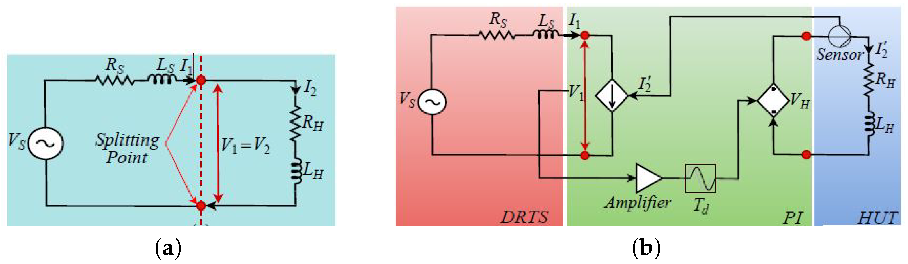
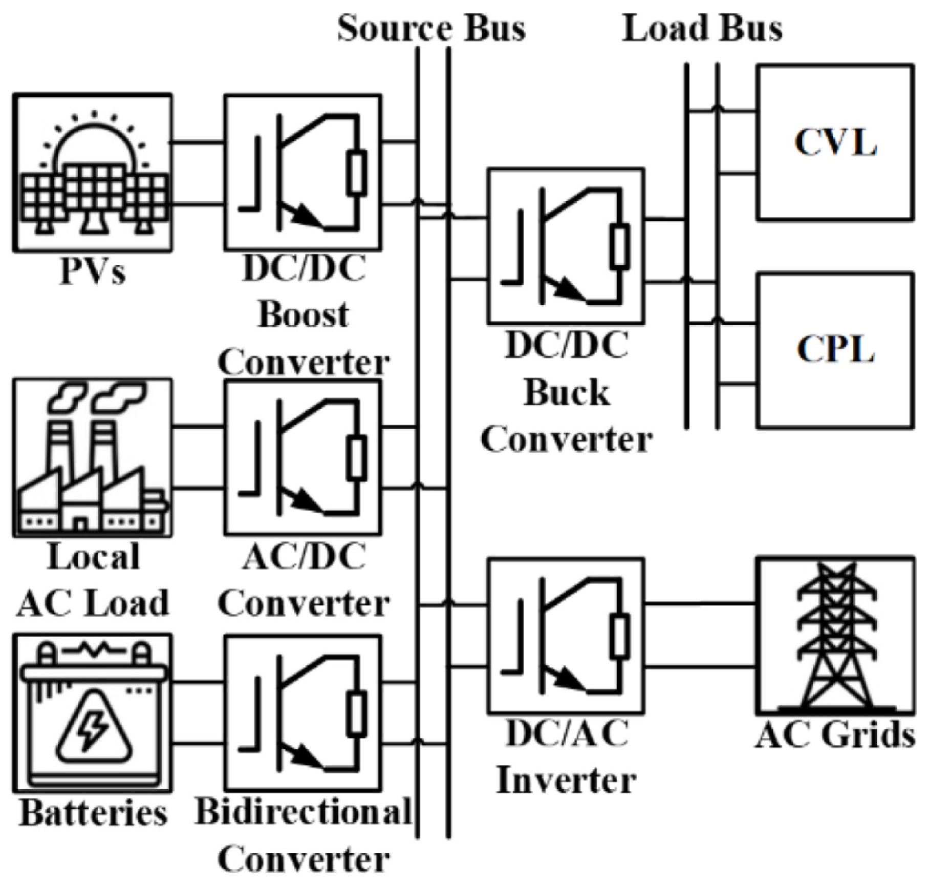
2.4. Power HIL Simulation for Grid Applications

PHIL simulations can be used for the testing of an electric component, as well as for electric tests of hardware interacting with complex systems. The advantages of a pure software simulation and a hardware system test are combined by using PHIL simulations. At present, PHIL simulations, unfortunately, are not “plug and play”, and prior to starting a PHIL experiment in a laboratory, some crucial considerations have to be noted. The contributions in [50,51] focus on the improvement of the connection between the hardware part of a PHIL simulation with the real-time computing system through the introduction of an additional current filter into the feedback path. The stability margin of the simulation setup improves drastically with the added filter. This method employs a PV inverter connected to a low voltage AC grid with linear and nonlinear loads. The PV inverter is connected as real hardware to the simulation environment, while the low voltage AC grid and the loads are simulated. The stable PHIL experiment that gains insight into the interaction between the PV inverter and the nonlinear load is assured by the introduced feedback current filter.
The controllability, usability, and implementation of the key components are crucial for the setup of a PHIL simulation. The real-time capability of models, solvers, and computing systems is required urgently for setting up fast PHIL simulation systems. Modern simulation methods are important for fast and efficient PHIL simulations [51] (see Figure 29). The Pejovic or associated discrete circuit (ADC) solver [79] is a particular type of classic nodal admittance (CNA), in which the admittance matrix remains constant, even with switches that change status (ON/OFF). The switches are modeled with small inductance in the ON state and a small capacitance in the OFF state. The method is exceptionally rapid because it requires no matrix inversion or lower/upper (LU) factorization during the real-time loop.

Grid Applications and Power HIL Simulation Examples

Increased penetration of high-voltage DC (HVDC) and flexible AC transmission systems (FACTS) in the AC network impact the grid performance and reliability. When HVDC links are connected nearby, such devices may have unwanted interaction and affect the AC network’s performance. Vendors, utilities, or third parties conduct off-line and real-time simulations to assess these risks. The objective in [52] is to describe the use of HIL simulation with physical control and protection (C&P) cubicles in an industrial context. The electricity transmission system operator of France—RTE (Réseau de Transport d’Électricité) facilities conducts three innovative projects with a focus on interaction studies, and [52] presents the results. Each case provides challenges and experiences for interaction studies in HIL simulations.
A demanding drastic reduction of greenhouse gas emissions in the energy sector requires a fundamental transition of the energy supply, affecting the grid’s stability [53,54]. Today, we face a significant increase in distributed energy resources (DERs), such as wind power plants, solar PV, and battery energy storage systems (BESS), into the electric grid. These additional generation units are spread out in the distribution grid, and create a new situation where the power does not flow in one direction from the transmission grid down to the distribution grid, but also flows back up to the transmission grid. In [55] a Phasor-based control (PBC) approach is proposed for DERs control, with the goal to relieve various constraints in the distribution grid.
PHIL simulations enable large-scale power systems to be tested and verified in the real-time simulation environment. They offer an effective way to conduct a non-destructive investigation of the complex power system in extreme scenarios. In [53], the authors propose a hybrid compensation scheme to compensate for the time delay in the PHIL configuration, in order to synchronize the PHIL output signal and promote the accuracy and stability of the PHIL simulation. Figure 30 illustrates the PHIL configuration with a naturally coupled power system and voltage-type ideal transfer model (ITM) interface algorithm. Here, the authors implement a model-based compensator to shift the time delay out of the PHIL closed loop, to improve the PHIL stability where a time delay compensation model and its equivalent inverse model are employed for this purpose. A digital linear-phase frequency sampling filter (FSF) and phase lead compensator were employed as compensation models for the time delay compensation, and for reshaping the phase curve on a harmonic-by-harmonic basis. The performance and effectiveness of the proposed hybrid scheme for the stability improvement and phase curve reshaping were verified through time-domain simulation results.
In [56], an adaptive continuous control set model predictive control (CCS-MPC) is proposed to solve the instability problem caused by the constant power load (CPL) in a DC-DC buck converter in DC microgrids. Wide application of new efficient energy systems, DC micro-networks, appear in data centers, telecommunications power systems, and electric transport (such as EVs, ships, and aircraft). Figure 31 shows a typical structure of a DC microgrid with cascaded distributed power architectures. The applied parallel feed-forward algorithm (PFA), which is designed to estimate the load and input voltage variations, is based on the energy storage elements in the circuit (inductor and capacitor) dynamic models. Here, the MATLAB simulations, rapid-control-prototype (RCP) and HIL experimental results, verify the robustness of the adaptive CCS-MPC controller. Moreover, an investigation of its dynamic performance, comparative simulations, and HIL experiments confirm its superiority against other nonlinear controllers.
In [57], the authors consider the built-in three-phase transmission line models based interfacing technique. The models that are available through simulation platforms perform the real-time root mean square (RMS)- electromagnetic transient (EMT), multi-rate, and multi-domain co-simulation. The main objective here is to show the application of this kind of simulation in HIL testing of protecting relays. Therefore, the authors consider two well-known platforms: OPAL-RT with its ePhasorSym tool for RMS simulation, and RTDS for EMT simulation. However, due to its sufficient generality, the proposed technique can be applied on other real-time simulation platforms with similar built-in transmission line models.
In today’s development of wind turbine test benches, manufacturers conduct realistic ground-level tests using HIL systems. In [58], a state-of-the-art of test rigs is presented, equipped with an innovative HIL system that enables ground-based testing of full-scale wind turbines in the multi-megawatt regime. A state estimator and an internal wind turbine model comprising an aeroelastic rotor model for reference generation are integral parts of control loops for the setpoint tracking and active drivetrain damping of the proposed system. As shown in Figure 32, with HIL functionality, the equipped test rig consists of software parts such as electric motors, and hardware parts such as the wind-load-unit (WLU), which form the test bench’s drive unit and power the mounted device under test (DUT) mechanically. The introduced HIL simulation system at a test rig with a mounted state-of-the-art 3MW full-scale wind turbine is validated experimentally in detail. The obtained experimental results confirm that the system is able to emulate the cabin ground level drivetrain dynamics, while assuring stable operation over the full wind speed range.
An active disturbance rejection controller (ADRC) based MPPT strategy is proposed in [59], with the goal to improve the efficiency of the wind power generation, where an HIL test system is used, based on the LabVIEW FPGA platform (Figure 33). The whole configuration, mathematical model, operation principle, and MPPT control strategy of the wind power generation were analyzed first. Finally, the authors conducted the HIL real-time simulation tests under various wind speed conditions. The presented results prove the efficiency of the ADRC-based MPPT strategy, and demonstrate that the HIL system is a suitable tool for the development of wind power generation plants.

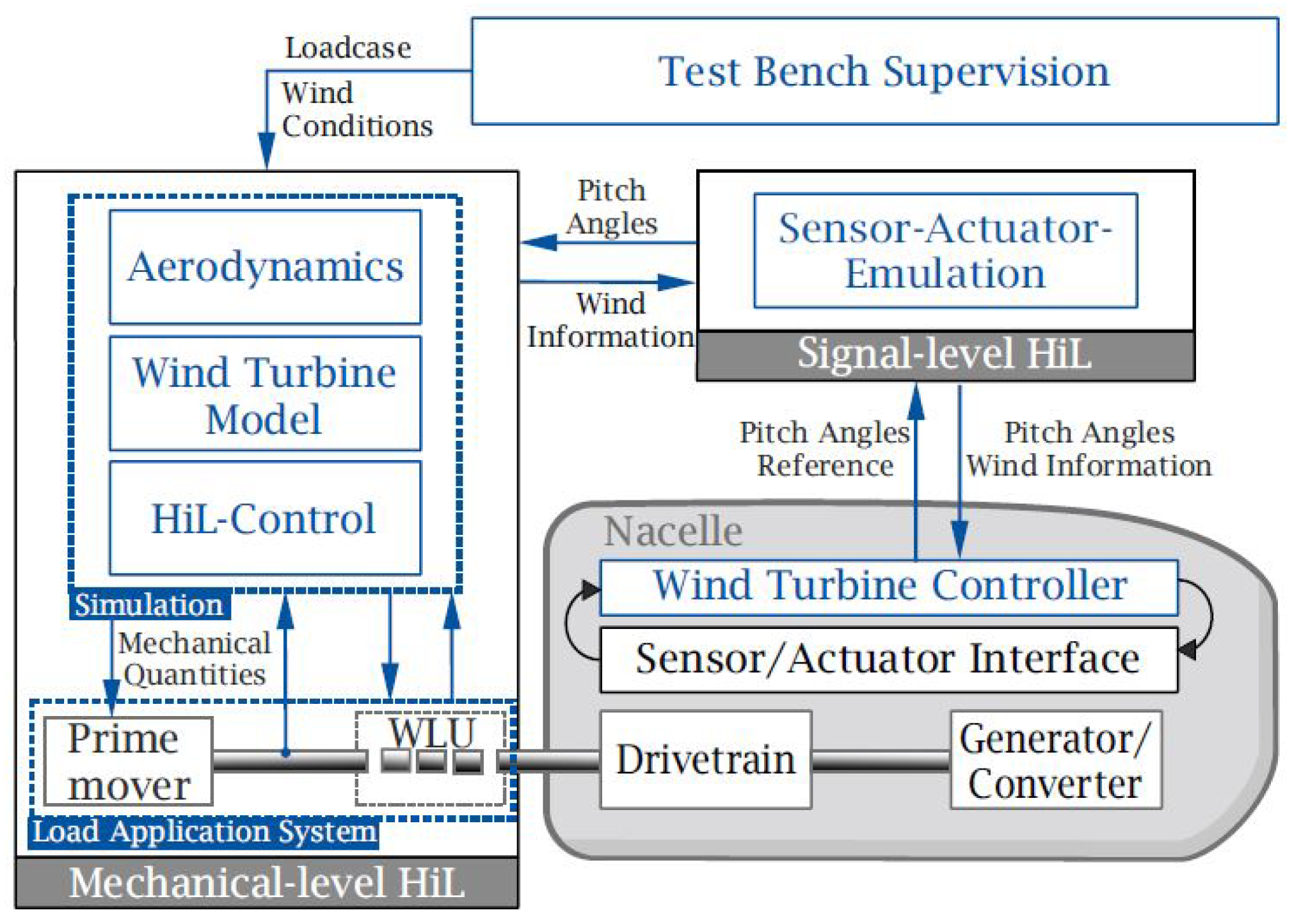
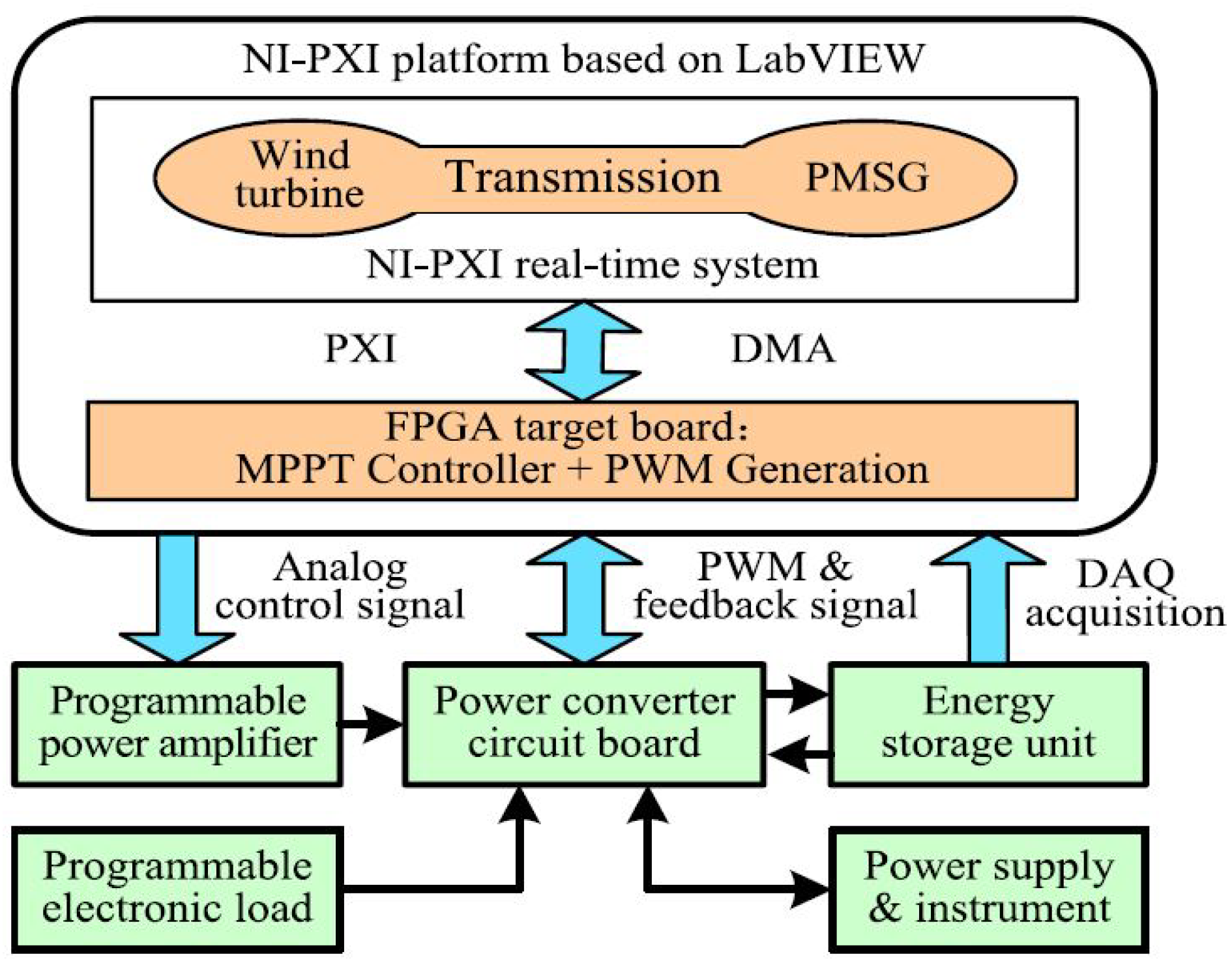
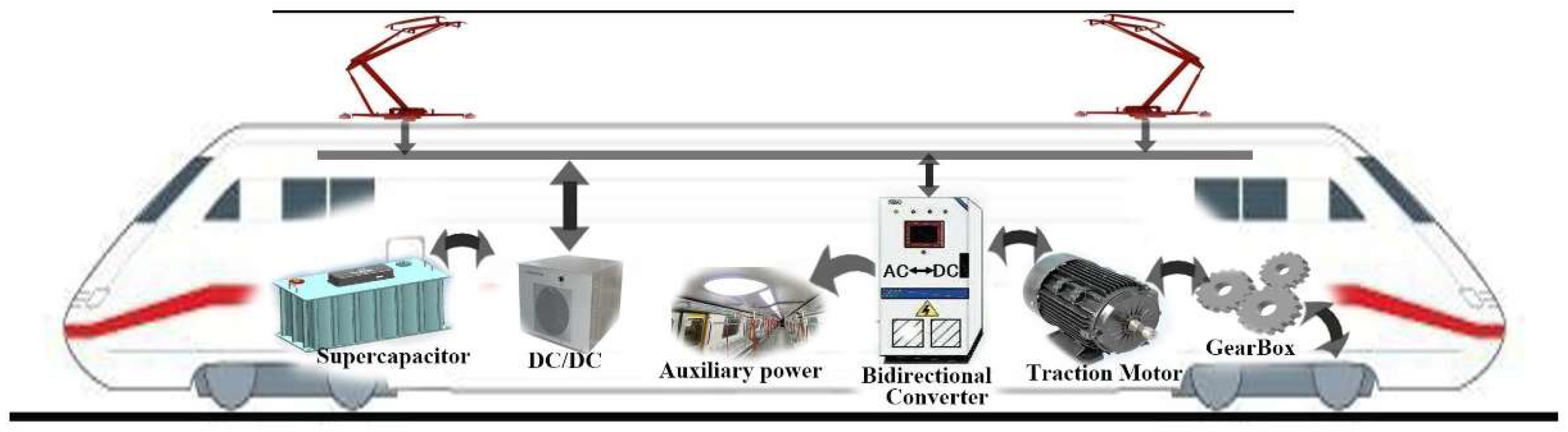
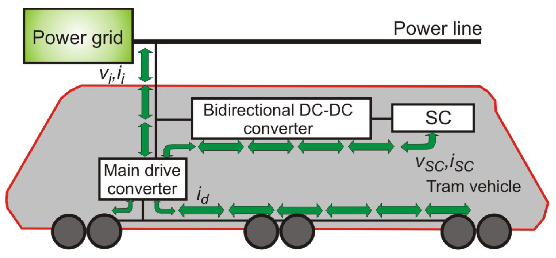
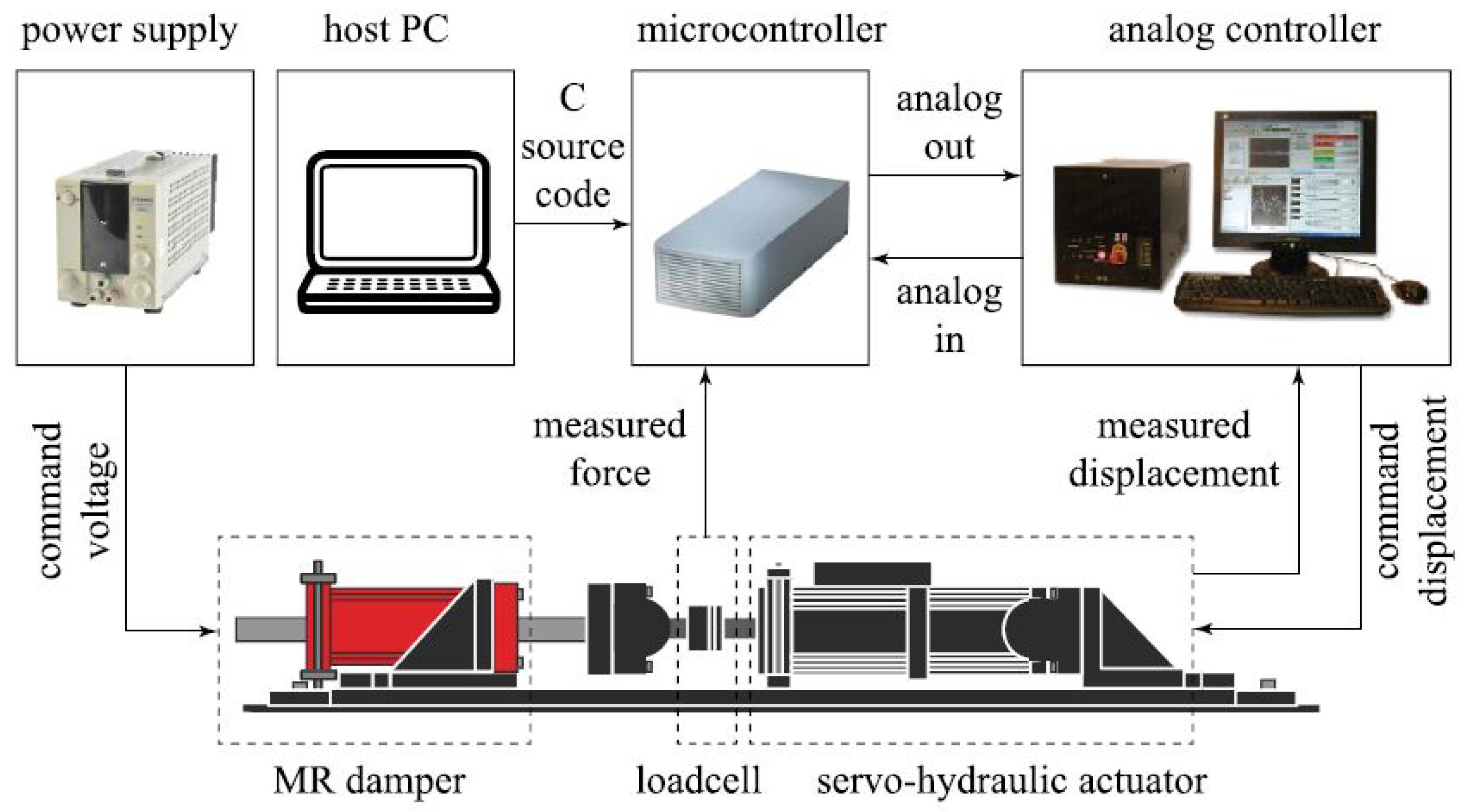
2.5. HIL Simulation in Railway Systems

The electrification of rail transport is improving all the time. With the increasing scale of urban rail transit, the energy waste cause at a train’s electric braking has been also growing. Usage of an on-board energy storage device [60,61] provides an effective energy-saving scheme that absorbs the regenerative braking energy of an electric train. In high-power electric-drive systems, such as railway vehicles, regenerative braking systems are an efficient way to decrease the energy waste, and, thus, increase the energy efficiency. The stability of the supply network can also be improved.

Railway Systems and HIL Simulation Examples

Depending on the design of the regenerative braking system, a semi-autonomous driving of the rail vehicle, i.e., driving without using energy from the power line, is a realistic solution. Testing a regenerative braking system in an electric vehicle during development is costly and potentially dangerous. For this reason, HIL simulation where the physical parts of the system are replaced by the simulation models, is a valuable and helpful technique to provide the real-time system’s testing. In [60], a control strategy utilizing regenerative braking energy with an on-board supercapacitor (SC) for energy saving is researched in detail. After modeling the electric train’s equivalent circuit model (Figure 34), the analysis of the on-board SC charge and discharge processes is conducted, based on its simplified model. Using the relation of the SOC at the SC development, the energy consumption function of the electric train based on the power flow is obtained, and the multi-objective optimization function is derived.
A description of the operation mode of an electric train can be as follows: Partial Power (PP), Full Power (FP), Coasting (C), Partial Brake (PB) and Full Brake (FB). Furthermore, the description of the SC operating mode can be as follows: Partial Charge (PC), Full Charge (FC), Hold (H), Partial Discharge (PDC) and Full Discharge (FDC). Let the variable μ be an equivalent to the tractive force coefficient of the train, and the variable ξ an equivalent to the working mode of the SC. Then, in Figure 35, the corresponding relationship is shown between ξ and μ . The objective function is solved with the dynamic programming (DP) based approach that is verified by simulations. The simulation results illustrate that the weight coefficient of each objective function affect the saved energy amount, and the most extensive energy-saving ratio is up to 18.23%.
In [61], the authors presented a HIL simulation of a tram regenerative braking system performed on a scaled model of a tram vehicle. First, by using a measured speed profile to validate the tram, the SC, power grid model, and the energy control algorithm simulations are enabled off-line. The voltage and current references for SC are related to the actual train speed, and calculated based on the train’s inertial forces and SC SOC [80]. Verification of the results follows in the real-time HIL simulation experiment, in which the tram and power grid emulation is possible using LiFEPO4 batteries and a three-phase converter. The three-phase bidirectional converter, which enables the energy flow within the regenerative braking system, is controlled by the energy flow controller, as shown in Figure 36. Finally, the results of a scaled model validate and confirm the applicability of the simulated regenerative braking system in a tram vehicle.
It is also essential to consider the dynamic response of railway bridges, as the risk of resonance is increased by trains’ high-velocity dependent loading. Increasing train speeds and loads demands the elastic properties of railway bridges [62]. One solution is installing magnetorheological dampers, as the structure’s response originating from moving loads could be controlled by alternating the input current to the damper (Figure 37 provides a schematic of the hardware and experimental setup). However, such units’ complexity results in problems in modeling their behavior accurately. In this context, a numerical bridge model and a full-scale physical magnetorheological damper are integral parts of a test frame. Nevertheless, similar approaches were applied previously for other types of structures and external loads in studies covering HIL simulations.

2.6. Power HIL Simulation and Education

MATLAB by MathWorks, Inc. [81] is used widely in the dynamic system and controls analysis and simulation areas in the industry and at universities for educational purposes. MATLAB with add-on components called toolboxes is the primary “engine”. Simulink is a MATLAB add-on that provides a graphical user interface for model development and system simulation [9]. The real-time toolboxes and Speedgoat real-time target machines (see Figure 38) can generate real-time code for Simulink models [10], and take you from simulation to RCP and HIL testing in a single click. Every target machine is configured to meet your specific requirements, such as sample rates and I/O. Simulink driver blocks, example models and cables, as well as terminal boards, allow you to configure all I/O and protocols seamlessly, and to connect with your test infrastructure. It generates, compiles, and creates real-time executable code for Simulink models, eliminating the need for the user written low-level code. The capabilities of MATLAB, not only in the digital prototyping arena, but also in the HIL arena, are enhanced greatly with add-on components called toolboxes. All real-time target machines can be scaled and expanded without compromising latency or performance. Fully developed fletched rack systems enable maximum exploitation with multiple interconnected systems, such as real-time target machines, uninterruptible power supplies, inverters, and power amplifiers. Finally, students can generate real-time code quickly with minor changes. They can simulate and test control designs and the dynamics of electric vehicles and powertrains, wind turbines, electric motors, power converters, battery management systems, autonomous systems, robots and manipulators, and other devices. It is a valuable teaching tool, meaning that the learning and understanding of fundamental concepts presented in class can be enhanced and reinforced, by providing the real-time HIL response, where the changes in the reference input or control parameters help to explain the system’s behavior.

Education and Power HIL Simulation Examples

Nevertheless, in [63,64,65,66], the authors discuss the development of real-time digital control systems with HIL for modeling and controls’ education. Using a single environment for analysis of dynamic systems, development of control laws, and simulation evaluations has many advantages when compared to multi-environment systems. That is especially true in educational setups where students are not required to learn and get familiar with several software tools. This approach frees up time for activities that strengthen the learning of the presented basic concepts.
Furthermore, the authors in [63] discuss the software and hardware tools used in developing and implementing the educational environment for digital control algorithm development and testing. Figure 39 shows the structure of the overall host-target real-time control system. The control algorithms using Simulink blocks, and the interactive real-time system monitoring are implemented on the host–target environment. The interactive feature is helpful in an educational environment. Another important advantage of using MATLAB-based tools is that the controller operation verification is possible before switching to the real HIL. The fast experimentation and performance comparison between real and simulated systems is enabled when a single environment is used for both Simulation and HIL control.
In addition to [63], the following article from the same authors, Ref. [64], discusses the case where an HIL magnetic levitation (maglev) device is part of a real-time digital control environment used for modeling and controls’ education purposes, with the focus on neural network (NN) feedforward-loop control. This real-time digital control environment consists of two personal computers (host and target). The advanced control algorithms realized by using Simulink blocks (allowing the interactive real-time system monitoring and experimentation) are implemented in the host–target environment. Thus, the students could compare the developed algorithms’ performance, discuss each algorithm’s merits, and decide which approach should be selected, with respect to the process requirements, easily.
Last but not least, within our research group, HIL simulation is also present during the education process, confirming one master thesis in this study year [66]. This master’s thesis presents the testing of a realistic system applied in the automotive industry using the HIL method. Figure 40 shows the HIL testing approach, in which the hardware tested is a built-in controller, and the system model replaces (simulates) the physical system.
We used the dSpace Scalexio LabBox equipment shown in Figure 41a [69]. The system includes a processor module with an Intel i7 processor, an FPGA module, a module with an input–output unit, and a module with controller area network (CAN) and local interconnect network (LIN) communication link.
In the HIL test case, the controller for the pump was under test. For testing on a real system, a physical pump with other components had to be provided, along with the possibility of changing environmental impacts. Based on the environmental changes, these would be detected by sensors, and, consequently, the controller would adapt the speed control of the pump. A simulated model replaced the pump and sensor’s physical model, which was done on an FPGA platform that allows real-time implementation. The pump model was implemented on the FPGA part of the simulated model, as this allows faster calculation of the motor responses than the processor. The physical controller (Figure 41b) is connected to LabBox over two harness connectors for the signal exchange, and to the computer via the CAN and LIN connections provided by Scalexio. The values that would otherwise have to be measured by sensors were simulated, and sent via communication links to the controller. The model was tested as to whether the measured values and responses matched the expected ones. On the processor part of the model inside Scalexio, the test cases were programmed as needed to be performed. The requirements obtained for one test case usually required relatively similar circumstances, but depending on the complexity of the test, they may have covered a slightly broader scope of verification of system performance. The benefits of HIL testing are prevalent, as triggering errors would be pretty difficult when testing on a real system. Meanwhile, in HIL testing, we can set the parameters, we want to check if necessary. Thus, error triggering depends only on the code in the test sequence carried out by ControlDesk. The start of the execution of the test was triggered by CAN communication. Finally, Figure 42 shows an example of the operation of the HIL system when an error is triggered in step 5.11, leading to a successful pump test.
Figure 42 merely presents one test sequence executed on the HIL system to get an insight into testing procedures. Not to go into detail, the signals are prepared and presented in a ControlDesk environment for the pump test consisting of six steps. The introduced test includes a change in the amplitude of the position sensor with the intent to trigger a fault. System calibration and steps with correct fault detection are performed consequently. The faulty operation is detected clearly, providing two pulses in the 6th and 7th signals in the row where the deviance in the amplitude is detected, and the fault is triggered with the measured time response.
At the end of the test sequence, the data were saved, including the history of the CAN communication and the signals being read. Thus, it is possible to review and evaluate the test later without the need for additional measurements repeatedly. The graph in the ControlDesk also contains a time indicator that displays the values of all signals on the graph at a given time. This was an indispensable tool in evaluation. ControlDesk allows data to be stored so they can also be read with Python code, allowing the automatic evaluation of tests.

3. Conclusions

In summary, a setup that prototypes parts of a given system in hardware is a HIL simulator. By sustaining the bidirectional information flow between these physical and virtual subsystems, a HIL simulator emulates the rest virtually. A controller design and testing by integrating a control unit into hardware with virtual models of the devices and controlled systems is the most traditional application of the HIL simulation concept.
Recently, the HIL simulation concept has spread and become essential in different steps of the system life cycle, such as the design, development, implementation, and testing of various applications in the aerospace, automotive, marine, and defense industries, robotic systems, and power lines. The system’s efficiency and reliability can be increased in a practical way by using suitable hardware in the loop during different system design stages. Additionally, in the software and hardware design procedure, many errors, as well as their interconnections, can be avoided by proper investigation. The growing activities of HIL simulation confirm its benefits, including the following:
  • Cost effectiveness;
  • Rapid prototyping;
  • Fidelity and verisimilitude (credibility);
  • Simulation speed;
  • Repeatability and stability;
  • Non-destructive nature;
  • Comprehensiveness;
  • Flexibility;
  • Parameter study, sensitivity analysis and optimization;
  • Safety;
  • Concurrent system engineering;
  • Automated testing.
Due to its many significant advantages, and because there is no alternative for particular situations, one could hardly criticize HIL systems as an approach. Nevertheless, the shortcomings of HIL systems can be recognized as follows:
  • No standard solutions, slow integration;
  • No internal system under test information;
  • Non-perfect virtualization and parameters, such as bus length, terminations, and back-feeding voltages related issues.
A HIL simulator will not give any information directly about the state of the tested control system since it only acts as a black box tester. It can only read the embedded system’s output. When the embedded software goes wrong, there may or may not be enough information in those few outputs to determine what part of the software was executing, or what the values of the internal variables were. The disadvantages are also the time-consuming preparations of test scenarios for the abnormal and faulty conditions, where the whole HIL system must be tuned from the model to the final real-time signal execution to expose the faulty operation. Preparing the tests to identify faulty operations is often more time consuming than the test execution itself. With the increased complexity of models and integration of different tools in the HIL system, the upload time to the processor/execution part is also extended.
Generally, the HIL simulation concept has become state of the art in supporting development activities in different industries, and universities are integrating this concept rapidly into engineering study programs.

Author Contributions

Conceptualization, F.M. and M.T.; methodology, F.M.; validation, F.M., M.T. and A.H.; formal analysis, F.M., M.T. and A.H.; investigation, F.M.; resources, F.M.; data curation, F.M., M.T. and A.H.; writing—original draft preparation, F.M.; writing—review and editing, F.M.; visualization, F.M.; supervision, F.M., M.T. and A.H. All authors have read and agreed to the published version of the manuscript.

Funding

This research was funded by the Slovenian Research Agency (Research Core Funding No. P2-0028).

Institutional Review Board Statement

Not applicable.

Informed Consent Statement

Not applicable.

Data Availability Statement

Not applicable.

Conflicts of Interest

The authors declare no conflict of interest.

Abbreviations

The following abbreviations are used commonly in this manuscript:
ACAlternating current
ANNArtificial neural network
BCMBoundary continuous mode
BESSBattery energy storage resource
BEVBattery electric vehicle
CCMContinuous conduction mode
CHILController HIL
CPLConstant power load
DCDirect current
DCMDiscontinuous conduction mode
DOFDegree of freedom
DSPDigital signal processor
DUTDevice under test
ECUElectronic control unit
EILEngine in the loop
ELEElectronic load emulation
ESAEuropean Aviation Safety Agency
ESPMEquivalent small parameter method
FAAFederal Aviation Administration
FPGAField programmable gate array
HDLHardware description language
HEVHybrid electric vehicle
HILHardware-in-the-loop
HUTHardware under test
HVDCHigh-voltage DC
ICInternal combustion
MLIMultilevel inverter
MPPTMaximum power point tracking
PFCPower factor correction
PHEVPlug-in hybrid electric vehicle
PHILPower HIL
PVPhotovoltaic
RCPRapid control prototype
SMPSSwitching mode power supply
SOCState of charge
SPWMSine pulse width modulation
THDTotal harmonic distortion
VHSICVery high-speed integrated circuits
VPVirtual prototype
WLUWind load unit

References

  1. Maclay, D. Simulations get into the loop. IEE Rev. 1997, 43, 109–112. [Google Scholar] [CrossRef]
  2. Bacic, M. On hardware-in-the-loop simulation. In Proceedings of the Conference on Decision and Control/European Control Conference, Seville, Spain, 12–15 December 2005; pp. 3194–3198. [Google Scholar] [CrossRef]
  3. Dillard, A.E. Real-time operational evaluations using advanced flight simulators. In Proceedings of the Digital Avionics Systems Conference, Bellevue, WA, USA, 31 October–7 November 1998; pp. E16-1–E16-8. [Google Scholar] [CrossRef]
  4. Pace, P.E.; Nishimura, B.H.; Morris, W.H.; Surratt, R.E. Effectiveness calculations in captive-carry HIL missile simulator experiments. Trans. Aerosp. Electron. Syst. 1998, 34, 124–136. [Google Scholar] [CrossRef]
  5. Evans, M.B.; Schilling, L.J. The Role of Simulation in the Development and Flight Test of the HiMAT Vehicle. NASA Technical Memorandum 84912. 1984. pp. 1–37. Available online: https://ntrs.nasa.gov/citations/19840013469 (accessed on 30 May 2022).
  6. Leitner, J. Space technology transition using hardware in the loop simulation. In Proceedings of the Aerospace Applications Conference, Aspen, CO, USA, 10 February 1996; pp. 303–311. [Google Scholar] [CrossRef] [Green Version]
  7. Gomez, M. Hardware-in-the-Loop Simulation. Available online: http://jmargolin.com/uavs/jm_rpv2_npl_14.pdf (accessed on 26 May 2022).
  8. Ingalalli, A.; Satheesh, H.; Kande, M. Platform for hardware in loop simulation. In Proceedings of the SPEEDAM, Capri, Italy, 22–24 June 2016; pp. 41–46. [Google Scholar] [CrossRef]
  9. Simulink; MathWorks, Inc.: Natick, MA, USA; Available online: https://www.mathworks.com/products/simulink.html (accessed on 12 June 2022).
  10. Simulink Real-Time; MathWorks, Inc.: Natick, MA, USA; Available online: https://www.mathworks.com/products/simulink-real-time.html (accessed on 12 June 2022).
  11. Hanselmann, H. Hardware-in-the-loop simulation testing and its integration into a CACSD toolset. In Proceedings of the Computer-Aided Control System Design Symposium, Dearborn, MI, USA, 15–18 September 1996; pp. 152–156. [Google Scholar] [CrossRef]
  12. Vogt, S.M.; Klostermann, M.; Kundu, A.; Andruschenko, S.; Hofmann, U.G. Hardware-in-the-loop testing for closed-loop brain stimulators. In Proceedings of the ECIFMBE, Antwerp, Belgium, 23–27 November 2008; pp. 1128–1132. [Google Scholar] [CrossRef]
  13. Puschmann, F. Safe testing through power hardware-in-the-loop systems. ATZ Electron. Worldw. 2021, 16, 50–53. [Google Scholar] [CrossRef]
  14. Milanovič, M.; Rodič, M.; Truntič, M. Functional safety in power electronics converters. In Proceedings of the EDPE, Dubrovnik, Croatia, 4–6 October 2017; pp. 1–14. [Google Scholar] [CrossRef]
  15. IEC 61508-1:2020; Functional Safety of Electrical/Electronic/Programmable Electronic Safety-Related Systems—Part 1: General Requirements, Edition 2.0. IEC: Geneva, Switzerland, 2010. Available online: https://webstore.iec.ch/publication/5515 (accessed on 6 June 2022).
  16. ISO 26262-1:2011; Road Vehicles—Functional Safety—Part 1: Vocabulary. International Organization for Standardization: Geneva, Switzerland, 2011. Available online: https://www.iso.org/obp/ui/#iso:std:iso:26262:-1:ed-1:v1:en (accessed on 6 June 2022).
  17. RTCA Inc. DO-178C/ED-12C: Software Considerations in Airborne Systems and Equipment Certification; Technical Report DO-178C; RTCA Inc.: Washington, DC, USA, 2012; Available online: https://en.wikipedia.org/wiki/DO-178C (accessed on 6 June 2022).
  18. RTCA Inc. DO-254, Design Assurance Guidance for Airborne Electronic Hardware; RTCA Inc.: Washington, DC, USA, 2000; Available online: https://en.wikipedia.org/wiki/DO-254 (accessed on 6 June 2022).
  19. Bosch, R. (Ed.) Automotive Electrics and Automotive Electronics, 5th ed.; John Wily and Sons Ltd.: Hoboken, NJ, USA, 2007. [Google Scholar] [CrossRef]
  20. Isermann, R.; Schaffnit, J.; Sinsel, S. Hardware-in-the-loop simulation for the design and testing of engine-control systems. Control Eng. Pract. 1999, 7, 643–653. [Google Scholar] [CrossRef]
  21. Rabbath, C.A.; Abdoune, M.; Belanger, J.; Butts, K. Simulating hybrid dynamic systems. IEEE Robot. Autom. Mag. 2002, 9, 39–47. Available online: https://www.academia.edu/26135462/Simulating_hybrid_dynamic_systems (accessed on 2 August 2022). [CrossRef]
  22. Brennan, S.; Alleyne, A.; DePoorter, M. The Illinois roadway simulator-a hardware-in-the-loop testbed for vehicle dynamics and control. In Proceedings of the ACC, Philadelphia, PA, USA, 26 June 1998; pp. 493–497. [Google Scholar] [CrossRef]
  23. Fathy, H.K.; Filipi, Z.S.; Hagena, J.; Stein, J.L. Review of hardware-in-the-loop simulation and its prospects in the automotive area. In Proceedings of the Modeling and Simulation for Military Applications, Orlando, FL, USA, 17–21 April 2006; SPIE: Bellingham, DC, USA, 2006; Volume 6228. [Google Scholar] [CrossRef]
  24. Short, M.; Pont, M.J. Hardware in the loop simulation of embedded automotive control system. In Proceedings of the Intelligent Transportation Systems, Vienna, Austria, 16 September 2005; pp. 226–231. [Google Scholar] [CrossRef]
  25. Short, M.; Pont, M.J. Assessment of high-integrity embedded automotive control systems using hardware in the loop simulation. J. Syst. Softw. 2008, 81, 1163–1183. [Google Scholar] [CrossRef] [Green Version]
  26. Setlur, P.; Wagner, J.; Dawson, D.; Powers, L. A hardware-in-the-loop and virtual reality test environment for steer-by-wire system evaluations. In Proceedings of the ACC, Denver, CO, USA, 4–6 June 2003; pp. 2584–2589. [Google Scholar] [CrossRef]
  27. Fényes, D.; Fazekas, M.; Németh, B.; Gáspár, P. Implementation of a variable-geometry suspension-based steering control system. Veh. Syst. Dyn. 2022, 60, 2018–2035. [Google Scholar] [CrossRef]
  28. Etzold, K.; Fahrbach, T.; Herold, K.; Andert, J. Thermal Hardware-in-the-Loop Tests of Electric Traction Machines. ATZ Worldw. 2019, 121, 50–55. [Google Scholar] [CrossRef]
  29. Bagameri, N.; Varga, B.O.; Moldovanu, D.; Csato, A.; Karamousantas, D. Optimizing Shifting Schedule and Hardware-in-the-Loop Simulation of a Hybrid Vehicle Based on Dual Clutch Transmission. In Proceedings of the Automotive and Transport Engineering, Cluj-Napoca, Romania, 30 September 2018; pp. 320–327. [Google Scholar] [CrossRef]
  30. Dooner, M.; Wang, J.; Mouzakitis, A. Dynamic modelling and experimental validation of an automotive windshield wiper system for hardware in the loop simulation. Syst. Sci. Control Eng. 2015, 3, 230–239. [Google Scholar] [CrossRef]
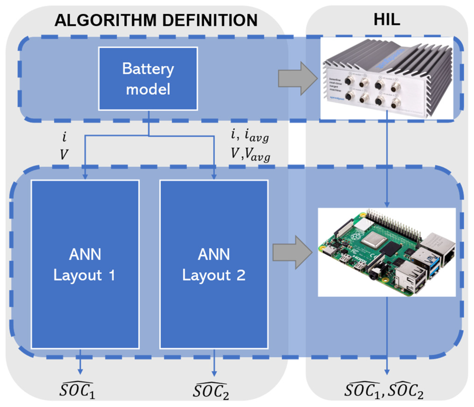
  31. Luciani, S.; Feraco, S.; Bonfitto, A.; Tonoli, A. Hardware-in-the-loop assessment of a data-driven state of charge estimation method for lithium-ion batteries in hybrid vehicles. Electronics 2021, 10, 2828. [Google Scholar] [CrossRef]
  32. Samiee, S.; Nahvi, A.; Azadi, S.; Kazemi, R.; Hatamian Haghighi, A.R.; Ashouri, M.R. The effect of torque feedback exerted to driver’s hands on vehicle handling—A hardware-in-the-loop approach. Syst. Sci. Control Eng. 2015, 3, 129–141. [Google Scholar] [CrossRef] [Green Version]
  33. Chung, Y.; Yang, Y.-P. Hardware-in-the-loop simulation of self-driving electric vehicles by dynamic path planning and model predictive control. Electronics 2021, 10, 2447. [Google Scholar] [CrossRef]
  34. Parodi, O.; Lapierre, L.; Jouvencel, B. Hardware-in-the-loop simulators for multi-vehicles scenarios: Survey on existing solutions and proposal of a new architecture. In Proceedings of the Intelligent Robots and System, St. Louis, MO, USA, 10–15 October 2009; pp. 225–230. [Google Scholar] [CrossRef] [Green Version]
  35. Parodi, O.; Creuze, V.; Jouvencel, B. Communications with Thetis, a real time multi-vehicles hybrid simulator. In Proceedings of the International Society of Offshore and Polar Engineers, Vancouver, BC, Canada, 6–11 July 2008; pp. 1–8. Available online: https://www.researchgate.net/publication/29608446_Communications_with_Thetis_a_Real_Time_Multi-vehicles_Hybrid_Simulator (accessed on 2 August 2022).
  36. Major, P.; Zghyer, R.; Zhang, H.; Hildre, H.P. A framework for rapid virtual prototyping: A case study with the Gunnerus research vessel. Ship Technol. Res. 2021; ahead of print. [Google Scholar] [CrossRef]
  37. Bouscayrol, A. Different types of hardware-in-the-loop simulation for electric drives. In Proceedings of the ISIE, Cambridge, UK, 30 June–2 July 2008; p. 2146. [Google Scholar] [CrossRef]
  38. Glumac, S.; Varga, N.; Raos, F.; Kovačić, Z. Co-simulation perspective on evaluating the simulation with the engine test bench in the loop. Automatika 2022, 63, 275–287. [Google Scholar] [CrossRef]
  39. Gundogdu, A.; Celikel, R.; Dandil, B.; Ata, F. FPGA in-the-loop implementation of direct torque control for induction motor. Automatika 2021, 62, 275–283. [Google Scholar] [CrossRef]
  40. Kähler, M.; Woernle, C.; Bader, R. Hardware-in-the-loop-simulaton of constraint elements in mechanical systems. In Computational Kinematics; Kecskeméthy, A., Müller, A., Eds.; Springer: Berlin, Germany, 2009; pp. 159–166. [Google Scholar]
  41. Adler, F.; Benigni, A.; Stagge, H.; Monti, A.; De Doncker, R.W. A new versatile hardware platform for digital real-time simulation: Verification and evaluation. In Proceedings of the COMPEL, Kyoto, Japan, 10–13 June 2012; pp. 1–8. [Google Scholar] [CrossRef]
  42. Yushkova, M.; Sanchez, A.; de Castro, A. Strategies for choosing an appropriate numerical method for FPGA-based HIL. Int. J. Electr. Power Energy Syst. 2021, 132, 107168. [Google Scholar] [CrossRef]
  43. Cirugeda-Roldan, E.M.; Martínez-García, M.S.; Sanchez, A.; de Castro, A. Evaluation of the different numerical formats for HIL models of power converters after the adoption of VHDL-2008 by Xilinx. Electronics 2021, 10, 1952. [Google Scholar] [CrossRef]
  44. Durbaba, E.; Akpinar, E.; Balikci, A.; Azizoglu, B.T.; Kocamis, A.E. Fast prototyping of a photovoltaic system by using DSP in MATLAB simulation loop. In Proceedings of the IECON, Lisbon, Portugal, 14–19 October 2019; pp. 1769–1773. [Google Scholar] [CrossRef]
  45. Wang, X.; Qiu, B.; Wang, H. Comparisons of modeling methods for fractional-order Cuk converter. Electronics 2021, 10, 710. [Google Scholar] [CrossRef]
  46. Zamiri, E.; Sanchez, A.; Yushkova, M.; Martínez-García, M.S.; de Castro, A. Comparison of different Design Alternatives for Hardwarein-the-Loop of Power Converters. Electronics 2021, 10, 926. [Google Scholar] [CrossRef]
  47. Lamo, P.; de Castro, A.; Sanchez, A.; Ruiz, G.A.; Azcondo, F.J.; Pigazo, A. Hardware-in-the-loop and digital control techniques applied to single-phase pfc converters. Electronics 2021, 10, 1563. [Google Scholar] [CrossRef]
  48. Stefanski, L.; Bernet, D.; Schnarrenberger, M.; Rollbuhler, C.; Liske, A.; Hiller, M. Cascaded H-bridge based parallel hybrid converter - A novel topology for perfectly sinusoidal high power voltage sources. In Proceedings of the IECON, Lisbon, Portugal, 14–19 October 2019; pp. 1639–1646. [Google Scholar] [CrossRef] [Green Version]
  49. Ansari, M.A.; Rahman, K.; Roomi, M.M.; Pervez, I.; Lodi, K.A.; Tariq, M.; Mishra, N. Solar PV fed three phase cascaded H bridge multi-level inverter. In Proceedings of the IECON, Singapore, 18–21 October 2020; pp. 3325–3330. [Google Scholar] [CrossRef]
  50. Lauss, G.; Lehfuss, F.; Viehweider, A.; Strasser, T. Power hardware in the loop simulation with feedback current filtering for electric systems. In Proceedings of the IECON, Melbourne, VIC, Australia, 7–10 November 2011; pp. 3725–3730. [Google Scholar] [CrossRef]
  51. Lauss, G.; Faruque, M.O.; Schoder, K.; Dufour, C.; Viehweider, A.; Langston, J. Characteristics and design of power hardware-in-the-loop simulations for electrical power systems. IEEE Trans. Ind. Electron. 2016, 63, 406–417. [Google Scholar] [CrossRef]
  52. Saad, H.; Rault, P.; Dennetière, S.; Schudel, M.; Wikstrom, C.; Sharifabadi, K. HIL simulation to assess interaction risks of HVDC systems for upcoming grid development. In Proceedings of the IECON, Singapore, 18–21 October 2020; pp. 5041–5048. [Google Scholar] [CrossRef]
  53. Feng, Z.; Peña-Alzola, R.; Seisopoulos, P.; Guillo-Sansano, E.; Syed, M.; Norman, N.; Burt, G. A Scheme to improve the stability and accuracy of power hardware-in-the-loop simulation. In Proceedings of the IECON, Singapore, 18–21 October 2020; pp. 5027–5032. [Google Scholar] [CrossRef]
  54. Resch, S.; Friedrich, J.; Wagner, T.; Mehlmann, G.; Luther, M. Stability analysis of power hardware-in-the-loop simulations for grid applicationss. Electronics 2022, 11, 7. [Google Scholar] [CrossRef]
  55. Baudette, M.; Swartz, J.; Moffat, K.; Pakshong, J.; Chu, L.; Gehbauer, C.; von Meier, A. Hardware-in-the-loop benchmarking setup for phasor based control validation. IFAC-PapersOnLine 2021, 54, 747–752. [Google Scholar] [CrossRef]
  56. Zhou, J.; Hassan, M.A.; Zhang, J.; Zhang, Z.; Wu, S.; Hou, M.; Li, Y.; Li, E.; Guerrer, J.M. A novel continuous control set model predictive control to guarantee stability and robustness for buck power converter in DC microgrids. Energy Rep. 2021, 7, 1400–1415. [Google Scholar] [CrossRef]
  57. Espinoza, R.F.; Justino, G.; Otto, R.B.; Ramos, R. Real-time RMS-EMT co-simulation and its application and its application in HIL testing protective relays. Electr. Power Syst. Res. 2021, 197, 107326. [Google Scholar] [CrossRef]
  58. Basler, M.; Leisten, C.; Jassmann, U.; Abel, D. Experimental validation of inertia-eigenfrequency emulation for wind turbines on system test benches. In Proceedings of the IECON, Singapore, 18–21 October 2020; pp. 205–212. [Google Scholar] [CrossRef]
  59. Wu, A.; Mao, J.-F.; Zhang, X. An ADRC-based hardware-in-the-loop system for maximum power point tracking of a wind power generation system. IEEE Access 2020, 8, 226119–226130. [Google Scholar] [CrossRef]
  60. Liu, W.; Xu, J.; Tang, J. Study on control strategy of urban rail train with on-board regenerative braking energy storage system. In Proceedings of the IECON, Beijing, China, 29 October–1 November 2017; pp. 3924–3929. [Google Scholar] [CrossRef]
  61. Pavlović, T.; Župan, I.; Šunde, V.; Ban, Ž. HIL simulation of a tram regenerative braking system. Electronics 2021, 10, 1379. [Google Scholar] [CrossRef]
  62. Tell, S.; Andersson, A.; Najafi, A.; Spencer, B.F., Jr.; Karoumi, R. Real-time hybrid testing for efficiency assessment of magnetorheological dampers to mitigate train-induced vibrations in bridges. Int. J. Rail Transp. 2021, 10, 436–455. [Google Scholar] [CrossRef]
  63. Shiakolas, P.S.; Piyabongkarn, D. Development of a real-time digital control system with a hardware-in-the-loop magnetic levitation device for reinforcement of controls education. IEEE Trans. Educ. 2003, 46, 79–87. [Google Scholar] [CrossRef]
  64. Shiakolas, P.S.; Van Schenck, S.R.; Piyabongkarn, D.; Frangeskou, I. Magnetic levitation hardware-in-the-loop and MATLAB-based experiments for reinforcement of neural network control concepts. IEEE Trans. Educ. 2004, 47, 33–41. [Google Scholar] [CrossRef]
  65. Kuperman, A.; Rabinovici, R. Virtual torque and inertia loading of controlled electric drive. IEEE Trans. Educ. 2005, 48, 47–52. [Google Scholar] [CrossRef]
  66. Sagmeister, P. System Models for HIL Testing in Automotive Industry on FPGA with dSpace Software. Master’s Thesis, University of Maribor, Maribor, Slovenia, May 2022. (In Slovene). [Google Scholar]
  67. Niechcial, F. LV 123: Understand Test Requirements and Implement Them Effortlessly. Electrical Normative Basics and Practical Challenges for Vehicle Components and Systems. Available online: https://www.volta.it/wp-content/uploads/2017/11/07-FN_LV-123_E_2017-06-06-Frank-Niechcial.pdf (accessed on 6 June 2022).
  68. ISO 21498-1; Electrically Propelled Road Vehicles—Electrical Specifications and Tests for Voltage Class B Systems and Components—Part 1: Voltage Sub-Classes and Characteristics. International Organization for Standardization: Geneva, Switzerland, 2021. Available online: https://www.iso.org/obp/ui/#iso:std:iso:21498:-1:ed-1:v1:en (accessed on 2 August 2022).
  69. dSPACE, ControlDesk: SCALEXIO. Available online: https://www.dspace.com/en/inc/home/products/hw/simulator_hardware/scalexio/scalexio_labbox.cfm (accessed on 29 June 2022).
  70. Simscape Multibody; MathWorks, Inc.: Natick, MA, USA; Available online: https://www.mathworks.com/products/simscape-multibody.html (accessed on 12 June 2022).
  71. Bose, B.K. Power Electronics and Motor Drives: Advances and Trends; Academic Press: Cambridge, MA, USA; Elsevier: Amsterdam, The Netherlands, 2006. [Google Scholar]
  72. Blaschke, F. A newmethod for the structural decoupling of AC induction machines. In Proceedings of the IFAC, Dusseldorf, Germany, October 1971; pp. 1–15. [Google Scholar]
  73. Mohan, N.; Undeland, T.M.; Robbins, W.P. Power Electronics and AC Drives, 2nd ed.; Prentice Hall: Hoboken, NJ, USA; John Wiley & Sons, Inc.: New York, NY, USA, 1989. [Google Scholar]
  74. Bryant, B.; Kazimierczuk, M.K. Small-signal duty cycle to inductor current transfer function for boost PWM DC-DC converter in continuous conduction mode. In Proceedings of the ISCAS, Vancouver, BC, Canada, 23–26 May 2004; pp. 856–859. [Google Scholar] [CrossRef]
  75. Das, S.; Pan, I.; Saha, S.; Kumar, A.; Das, S.; Gupta, A. Revisiting Oustaloup’s recursive filter for analog realization of fractional order differintegrators. In Proceedings of the International Conference on Energy, Automation and Signal, Bhubaneswar, India, 28–30 December 2011; pp. 1–6. [Google Scholar] [CrossRef]
  76. Sanchez, A.; de Castro, A.; López, V.M.; Azcondo, F.J.; Garrido, J. Single ADC digital PFC controller using precalculated duty cycles. IEEE Trans. Power Electron. 2014, 29, 996–1005. [Google Scholar] [CrossRef] [Green Version]
  77. López, F.; López-Martín, V.M.; Azcondo, F.J.; Corradini, L.; Pigazo, A. Current-sensorless power factor correction with predictive controllers. IEEE J. Emerg. Sel. Top. Power Electron. 2019, 7, 891–900. [Google Scholar] [CrossRef]
  78. Hacke, P.; Lokanath, S.; Williams, P.; Vasan, A.; Sochor, P.; TamizhMani, G.S.; Shinohara, H.; Kurtz, S. A status review of photovoltaic power conversion equipment reliability, safety, and quality assurance protocols. Renew. Sustain. Energy Rev. 2018, 82, 1097–1112. [Google Scholar] [CrossRef]
  79. Pejovic, P.; Maksimovic, D. A method for fast time-domain simulation of networks with switches. IEEE Trans. Power Electron. 1994, 9, 449–456. [Google Scholar] [CrossRef]
  80. Ciccarelli, F.; Iannuzzi, D.; Tricoli, P. Control of metro-trains equipped with onboard supercapacitors for energy saving and reduction of power peak demand. Transp. Res. Part C 2012, 24, 36–49. [Google Scholar] [CrossRef]
  81. Matlab; MathWorks, Inc.: Natick, MA, USA; Available online: https://www.mathworks.com/products/matlab.html (accessed on 12 June 2022).
Figure 1. HIL simulator: (a) Block diagram of embedded system connected to a HIL simulator; (b) components of a simple HIL simulator [7].
Electronics 11 02462 g001
Figure 2. The V-shape model for the development process [12].
Electronics 11 02462 g002
Figure 3. Validation procedure in the development cycle (© dSpace) [13].
Electronics 11 02462 g003
Figure 4. The functional safety development via V model [14].
Electronics 11 02462 g004
Figure 5. Comparison of software V cycle for aerospace and automotive [14].
Electronics 11 02462 g005
Figure 6. Interactions of physical and virtual prototypes: (a) when virtual models are driven; (b) when physical prototypes are driven and (c) with closed-loop (bidirectional) HIL simulation [23].
Electronics 11 02462 g006
Figure 7. HIL simulations: possible hybrid structures [20].
Electronics 11 02462 g007
Figure 8. Power HIL design (© dSpace) [13].
Electronics 11 02462 g008
Figure 9. Simulator user interface [25].
Electronics 11 02462 g009
Figure 10. HIL testing system for electric traction machines (© RWTH Aachen University) [28].
Electronics 11 02462 g010
Figure 11. Hybrid drivetrain model: (a) IPG CarMaker driveline model; (b) HIL system setup [29].
Electronics 11 02462 g011
Figure 12. V model for product development [19].
Electronics 11 02462 g012
Figure 13. State of charge estimation block scheme from [31].
Electronics 11 02462 g013
Figure 14. The 14-DOF model of the damping system [32].
Electronics 11 02462 g014
Figure 15. HIL simulation control system and experimental structure [33].
Electronics 11 02462 g015
Figure 16. Simplified architecture of Thetis [34].
Electronics 11 02462 g016
Figure 17. Software architecture for HIL, humans-in-the-loop virtual prototyping simulation [36].
Electronics 11 02462 g017
Figure 18. Mechanical level HIL simulation [37].
Electronics 11 02462 g018
Figure 19. The HIL simulation organized as a distributed simulation [38].
Electronics 11 02462 g019
Figure 20. Block scheme of the FPGA in-the-loop simulation [39].
Electronics 11 02462 g020
Figure 21. Mechatronic HIL joint simulator [40].
Electronics 11 02462 g021
Figure 22. Block diagram of the power electronic system [73].
Electronics 11 02462 g022
Figure 23. Digital real-time simulation system: (a) real-time simulator setup; (b) step-down converter [41].
Electronics 11 02462 g023
Figure 24. HIL simulation system: (a) general system architecture; (b) Simulink model of DC-DC boost converter [44].
Electronics 11 02462 g024
Figure 25. Block scheme of the HIL system with FPGA [46].
Electronics 11 02462 g025
Figure 26. Basic HIL simulation systems: (a) CHIL; (b) PHIL [47].
Electronics 11 02462 g026
Figure 27. Linear current control techniques in PFCs [47].
Electronics 11 02462 g027
Figure 28. Cascaded H-bridge multilevel inverter with PV modules in three-phase system [49].
Electronics 11 02462 g028
Figure 29. Relevant time steps in state-of-the-art simulation methods for real-time simulations [51].
Electronics 11 02462 g029
Figure 30. (a) A voltage divider system; (b) power HIL system with ideal transfer model interface algorithm [53].
Electronics 11 02462 g030
Figure 31. A generic scheme of DC microgrid systems [56].
Electronics 11 02462 g031
Figure 32. Relevant time steps for real-time simulation in state-of-the-art simulation methods [58].
Electronics 11 02462 g032
Figure 33. Architecture of the HIL system [58].
Electronics 11 02462 g033
Figure 34. The electric train with on-board super capacitor [60].
Electronics 11 02462 g034
Figure 35. The relation between ξ and μ [60].
Electronics 11 02462 g035
Figure 36. Regenerative braking system with indicated power flow in a tram [61].
Electronics 11 02462 g036
Figure 37. Experimental hardware and communication signals [62].
Electronics 11 02462 g037
Figure 38. Speedgoat real-time target computers [10].
Electronics 11 02462 g038
Figure 39. Host–target real-time control system structure [63].
Electronics 11 02462 g039
Figure 40. HIL testing setup.
Electronics 11 02462 g040
Figure 41. (a) The Scalexio LabBox modular real-time system; (b) the controller PCB.
Electronics 11 02462 g041
Figure 42. Example of successful test results.
Electronics 11 02462 g042
Publisher’s Note: MDPI stays neutral with regard to jurisdictional claims in published maps and institutional affiliations.

