Article

Seamless Capable PV Power Generation System without Battery Storage for Rural Residential Load

1
Department of Electrical Engineering, Chitkara University Institute of Engineering and Technology, Chitkara University, Punjab 140417, India
2
Department of Electrical Engineering, University of Kashmir, Srinagar 190006, India
3
BEARS, University Town, NUS Campus, Singapore 138602, Singapore
4
Division of Electrical Power Engineering, School of Electrical Engineering, Faculty of Engineering, Universiti Teknologi Malaysia (UTM), Johor Bahru 81310, Malaysia
5
Department of Electrical Engineering, National Institute of Technology Srinagar, Srinagar 190006, India
6
Department of Electrical Engineering, College of Engineering, King Saud University, Riyadh 11421, Saudi Arabia
7
Ingenium Research Group, Universidad Castilla-La Mancha, 13071 Ciudad Real, Spain
*
Authors to whom correspondence should be addressed.
Electronics 2022, 11(15), 2413; https://doi.org/10.3390/electronics11152413
Submission received: 15 June 2022 / Revised: 11 July 2022 / Accepted: 28 July 2022 / Published: 2 August 2022

Abstract

:
The presented system is a three-phase three-wire (3P–3W), seamless, capable, dual-stage PV power generation system without battery storage for rural residential loads to ensure a continuous power supply during the daytime. This system effortlessly shifts from the grid-connected (GC) mode to the standalone (SA) mode when the grid utility is unavailable. During the GC mode, a voltage source converter (VSC) is regulated by the polynomial zero-attracting least mean square (PZA-LMS) algorithm-based current control scheme. During the GC mode, the power balance is achieved at the point of common coupling (PCC) by exchanging active power with the grid, whereas the VSC delivers reactive power. Considering the low efficiency of PV power generation systems, an incremental conductance (InC)-based maximum power point tracking (MPPT) algorithm is necessary for the maximum power extraction out of a PV array. During the unavailability of the grid, the presented system operates in the SA mode, when the load is delivered with PV power only via VSC. Considering the high cost of the battery storage system (BSS), bi-directional converter, and charge control circuitry incurred by rural consumers, they were omitted from the system. Without a BSS, the InC-based MPPT is executed in the derated mode, extracting the PV power to exactly match the load demand. Without derated PV power generation operation, the load may be damaged due to excess PV power flow to the load end or the load may remain underpowered, leading to load shedding or complete disconnection. A synchronous reference frame (SRF)-based voltage control scheme is responsible for the VSC control during the SA operation of the system. The presented system performance was observed and found satisfactory during the irradiation variation, load balancing, islanding, and re-synchronization of the grid. The presented system was found to carry out harmonics suppression and active and reactive power balance at the PCC during both the GC and SA modes. The grid’s total harmonics distortion (THD) levels were shown to be kept below 5% as per the IEEE 519 standard in the GC mode.

1. Introduction

Renewable energy systems (RESs) have emerged as a reliable and viable option for green energy generation. With the latest advancements in power electronics and control techniques, end users’ acceptance of RESs has expanded multifold in the last decade. RESs have emerged as a sustainable, viable, abundant, and pollution-free energy source despite the scarcity of fossil fuels [1]. Worldwide, government policies encourage the growth and utilization of RESs [2]. The PV generation system predominates over the wind energy system in terms of lower initial investment, less maintenance, and a readily available and scalable nature. PV generation systems have become an obvious choice for low and medium-power rating plants for residential and commercial purposes.
Rural electrification is a challenging task for any developing country [3]. Moreover, maintaining a continuity of supply to the rural load is further complicated and exhaustive for the utilities. Rural consumers require photovoltaic (PV) power generation systems of low and medium power ratings. PV systems such as distributed generators (DG) reduce power transmission costs and losses and improve system reliability.
PV power generation can be achieved in standalone and grid-connected (GC) modes [4]. However, due to rapidly changing environmental conditions, PV power generation continuously varies, thus creating reliability issues. The demand and supply mismatch between variable PV power generation and local loads in a standalone PV system can only be managed with the use of an energy storage element [5]. Due to the possibility of hazards, a battery storage system necessitates additional installation space, frequent maintenance, a hefty initial cost, and careful supervision [6]. In contrast, grid-integrated PV systems exploit the grid as a battery storage system because of its electron bank property. The grid works as an infinite sink when the power generation is abundant. However, when the PV array power output is scarce, the grid serves as a constant voltage source, delivering load demand [7].
There are two types of PV power generation system configurations, i.e., single-stage and dual-stage [8]. The single-stage configurations consist of only one conversion stage: DC–AC via a voltage source converter (VSC). The single-stage PV system has better efficiency, fewer components, and lower control complexity, but it requires more PV panels in series that create a local hotspot in the PV array to match the adequate DC bus voltage V dc . A DC–DC boost converter is provided in the dual-stage configuration to maintain a stable PV voltage V PV during irradiation variation. Moreover, the dual-stage configuration of PV generation systems is globally preferred [9].
The use of a battery storage system (BSS) with a PV generation system improves the system’s reliability and helps maintain the continuous power supply to the load during the nighttime and the unavailability of the grid. However, the use of a BSS also has several drawbacks. Despite many advantages, the cost of a BSS is considerably high, around 50% of the total PV generation cost, making it less attractive to rural consumers [6]. Moreover, an use of a BSS with PV is not very effective in agricultural applications, e.g., water pumping. Another issue is the active power curtailment that occurs during excess PV power generation (when a BSS is fully charged and the grid is absent) in a PV–BSS system [10,11,12]. Due to excess PV power, V dc will increase and affect the system’s stability. Battery life is also adversely affected by excess PV power generation.
Due to the low efficiency of PV arrays, it is essential to extract maximum power out of them. Numerous maximum power point tracking (MPPT) algorithms for maximum power extraction (MPE) have been proposed in the literature. In [13,14], commonly used MPPT techniques and their classification and summarization were discussed along with their hardware implementations. Conventional MPPT algorithms, e.g., perturb and observe (P&O) and incremental conductance [15], are generally preferred over complex MPPT algorithms due to their ease of implementation, better tracking accuracy, and speed. Artificial intelligence-based MPPT techniques [16], e.g., artificial neural networks and fuzzy logic-based algorithms, have been proposed to achieve better steady-state performance, thus reducing power oscillations at the maximum power point (MPP). Several meta-heuristic optimization techniques have also been implemented to achieve MPPT during sudden irradiation change and partial shading conditions, i.e., whale optimization, particle swarm optimization, and salp swarm optimization. Considering its low computational complexity and adequate accuracy and tracking speed, the presented system was simulated with an InC-based MPPT algorithm in the GC mode [14]. During SA operation, the same InC MPPT was implemented in the derated mode to achieve excess PV power curtailment while maintaining the system’s stability. In [17], power oscillations reduction and stability enhancements were achieved with derated MPPT operation. In [10], modified P&O in the derated mode provided excess PV power curtailment. In [9], better power quality and fault ride-through capability were claimed with InC MPPT utilized during the GC mode and derated InC MPPT utilized during the SA mode. In [18], the cost-effectiveness of using a derated MPPT algorithm instead of a BSS was studied.
A seamless, capable PV generation system effortlessly allows for the transition of VSC control without any disturbance on the load and grid side [19]. During the GC mode, the grid acts as a battery, delivering required power at the point of common coupling (PCC) and absorbing the generated excess PV power. However, the integration of PV systems with the grid raises several power quality issues that are further alleviated during weak grid conditions, i.e., abnormal grid voltage, load unbalancing, rapidly changing irradiation levels, and faulty conditions [20]. An adequate VSC control with an effective filtering capability is essential for performing multifunctional operations, i.e., power quality enhancement at the PCC, load balancing, and active and reactive power balance [21]. Numerous VSC controls belonging to the time domain, frequency domain, and adaptive controls have been elaborated in the literature. The synchronous reference frame (SRF) technique belongs to the time domain, which has an adequate steady-state operation. The phase-locked loop in the SRF technique increases its computational complexity and reduces its convergence speed during the dynamic state [22]. Frequency-domain controls, e.g., Kalman filtering-based algorithms, suffer from a high computational burden. Extended Kalman filters are also widely acclaimed VSC controls, although their design and tuning are complex. The least mean square (LMS) and least mean fourth (LMF) are among the most widely used adaptive algorithms. The LMS algorithm offers better steady-state performance, but its performance deteriorates during the dynamic state. The LMF acts as a higher-order filter toward noise signals during a dynamic state, but its steady-state performance becomes compromised. Both LMS and LMF algorithms have sparse system identification. The advanced derivatives of LMS, i.e., hyperbolic cosine LMS (HCLMS) and variable step-size LMS (VSS-LMS), offer better filtering capabilities and convergence rates [23]. Maximum correntropy criteria (MCC)-based adaptive algorithms utilize Gaussian kernel function for handling Gaussian and non-Gaussian noises but suffer in system identification.
The zero-attracting (ZA) principle is used with adaptive control to detect near-zero coefficients [24]. The ZA-LMS and resized ZA-LMS (RZA-LMS) algorithms offer better system identification in which the near-zero coefficients are forced to zero. The presented system implements polynomial ZA LMS (PZA-LMS) for VSC switching signal generations. The objective function of PZA-LMS is made with the conjunction of l 0 norm and l 2 norm for the system identification [25]. The l 0 norm is approximated using an α order polynomial to achieve better filtering and convergence speed. During the SA mode, VSC control shifts from the current control algorithm to the voltage control algorithm [26], which also performs multifunctional operations, e.g., power quality improvements, delivers required reactive power to the load, and balances active power at the PCC.
The presented system is a seamless, capable, three-phase three-wire (3P–3W) PV generation system with battery storage for rural electrification as a BSS significantly increases the cost and payback period of PV generation systems. The proposed system utilizes the grid as a battery during the GC mode to maintain the PCC power balance, whereas during the SA mode, InC-based MPPT is operated in a derated mode to satisfy the load demand and active power curtailment. The PZA-LMS-based VSC control effectively identifies the noise signals due to the non-linearity of the load. It generates specific fundamental load current components for better filtering and faster convergence. The PZA-LMS performs multiple operations, i.e., harmonics elimination, load balancing, and active and reactive power balancing, during steady-state and dynamic states.
The main attributes of the proposed work are as follows:
  • The seamless transition of VSC control from PZA-LMS algorithm-based current control to SRF-based voltage control without any transient in the load and grid side.
  • InC MPPT operates in a derated mode to offer excess PV power curtailment, reduces overall cost in the absence of a battery, and results in a lower payback period.
  • The PZA-LMS algorithm offers better sparse system identification without forcing near-zero coefficients to zero, better filtering, and faster convergence speeds.
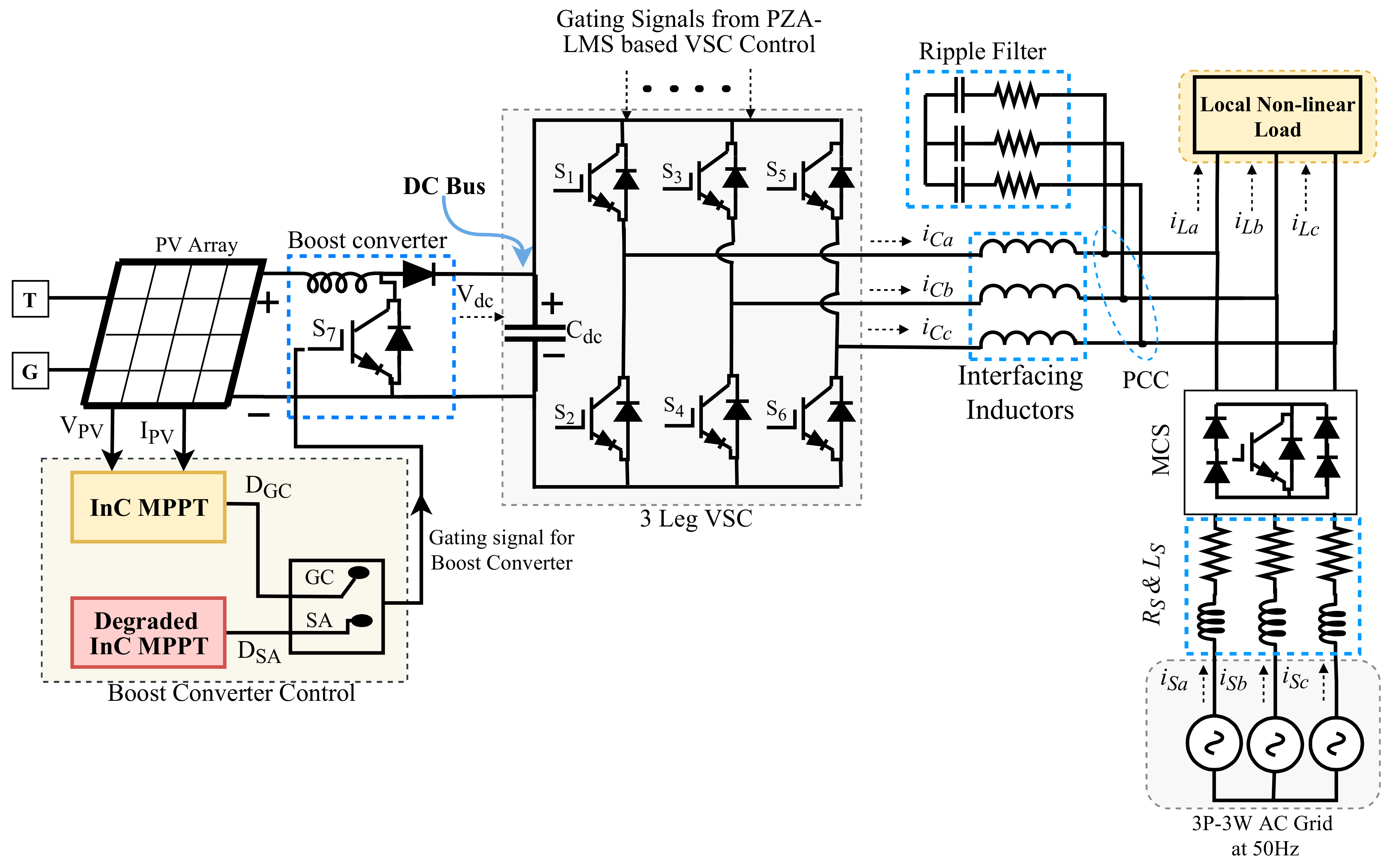
2. Proposed System

Figure 1 shows the presented system’s topology. A PV array of 32 kW is connected to the DC bus through the DC–DC boost converter, which the InC MPPT controls. During the GC mode, conventional InC MPPT performs MPE, whereas the same InC algorithms work in the derated mode during the SA mode for power curtailment. The coupling capacitor C d c acts as a DC bus. PZA-LMS controls the three-leg VSC during the GC mode and SRF during the SA mode. The ripple filters and interfacing inductors reduce the VSC voltage and current ripples. The three-phase grid is connected to the PCC through a master control switch (MCS) and non-linear load.

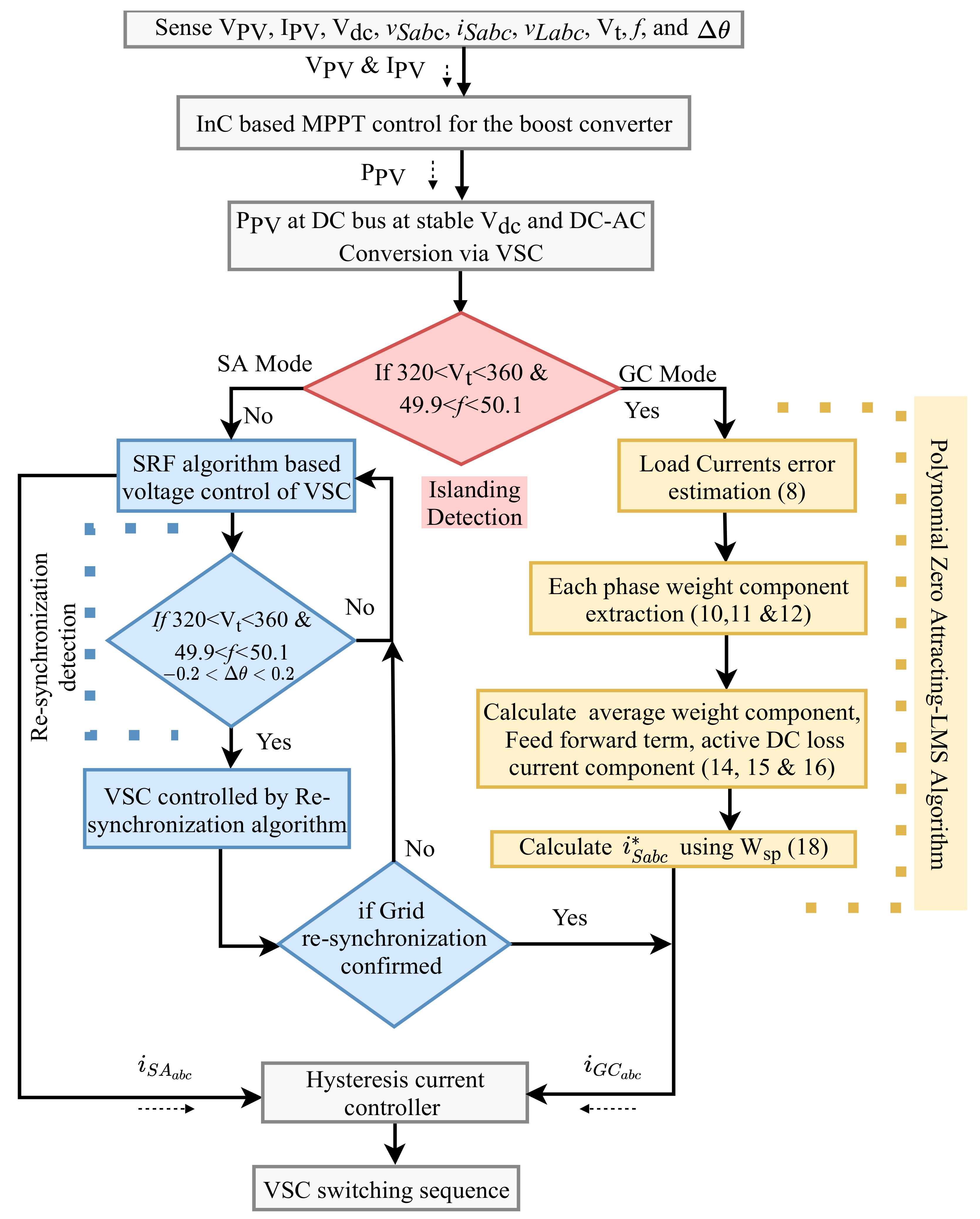
3. Research Methodology

Figure 2 shows the research methodology. PV voltage and current V PV   and   I PV , V dc , source voltages and currents v S a b c   and   i S a b c , load voltages and currents v L a b c   and   i L a b c , grid voltage magnitude V t , frequency (f), and phase angle θ are sensed by the system. The PV power P PV is delivered to the DC bus via a boost converter. The grid islanding is detected as per V t and f, which further make the system operate under the SA or GC modes, respectively. During the GC mode, PZA-LMS control generates the VSC switching pulses. During the SA mode, the SRF voltage control of VSC produces switching sequences. The incoming grid is re-synchronized by seamlessly shifting the VSC control from SRF voltage control to PZA-LMS control once the re-synchronization is confirmed.

4. Control Algorithms

The presented system function mainly utilizes two controls: (1) an InC MPPT and derated InC MPPT-based boost converter control and (2) a PZA-LMS-based VSC control.

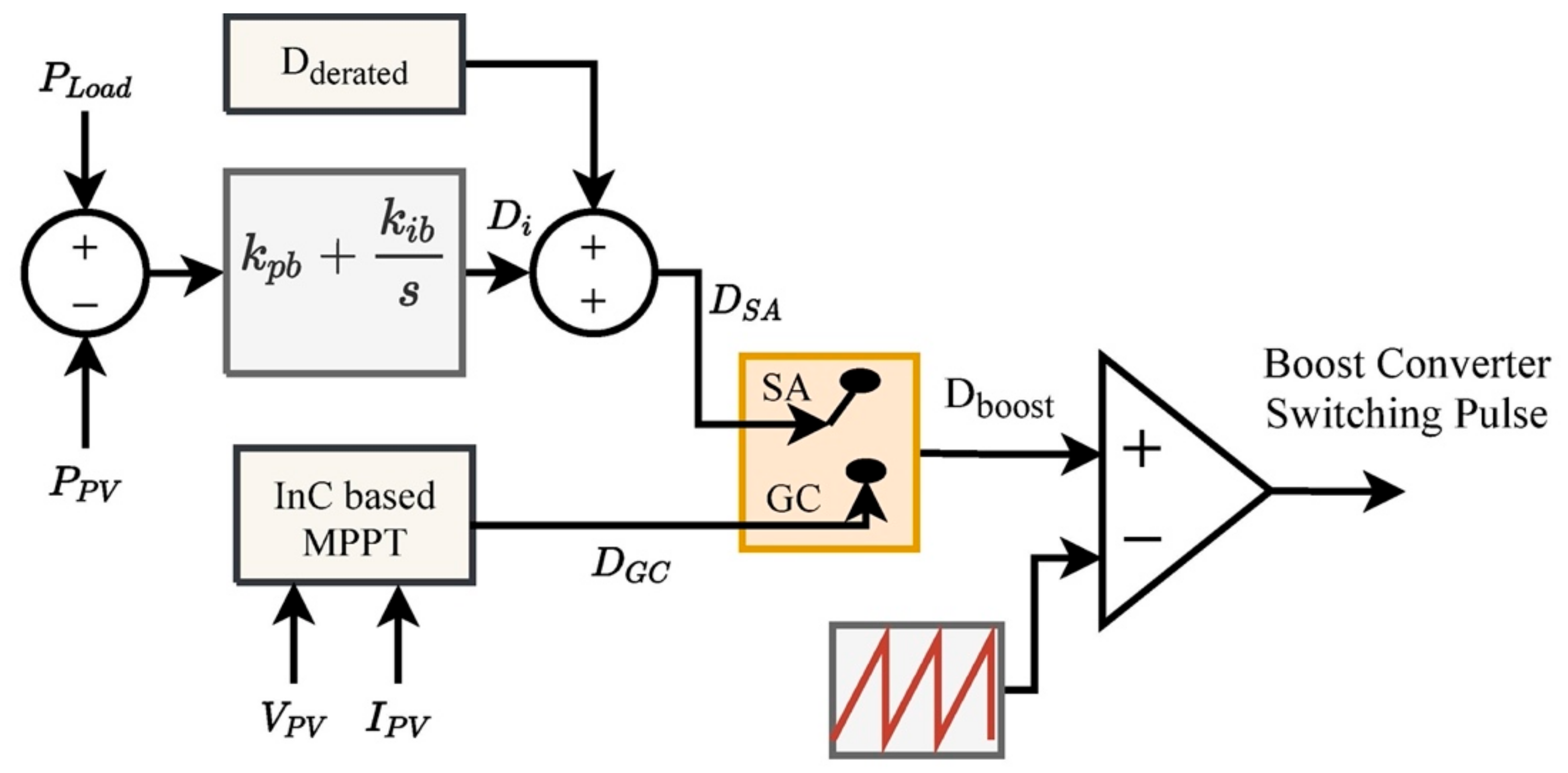
4.1. InC MPPT Control in GC Mode

The InC algorithm is employed for MPE out of the PV array during GC operation. The sensed V PV and P PV deliver the duty cycle D GC by applying the chain rule of derivatives of products, resulting in:
Δ I PV Δ V PV = I PV V PV
At   MPP   Δ I P V Δ V P V = 0
D G C = 1 V PV V dc

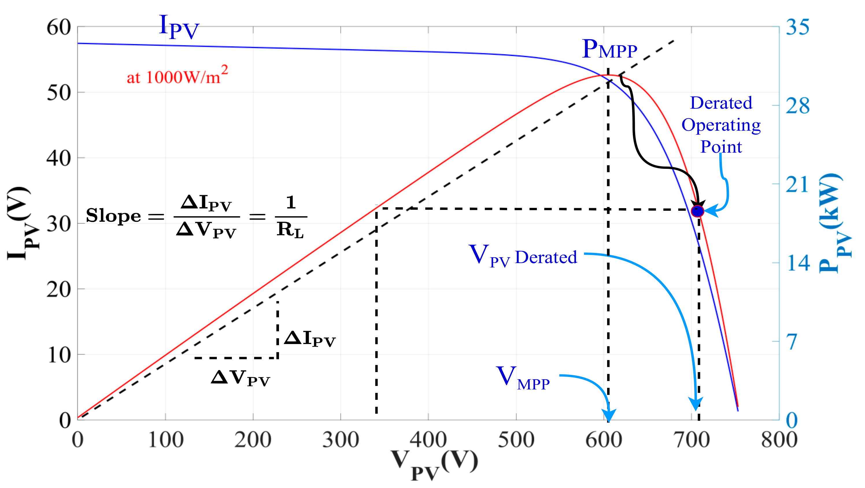
4.2. Derated InC MPPT Control in SA Mode

Figure 3 shows the boost converter control algorithm during the SA mode. The comparison of load demand ( P Load ) and P PV is provided to the proportional integral (PI) controller, and D d e r a t e d is added to incorporate the load requirement term as:
D d e r a t e d = P PV P Load 1 V PV V dc
Overall D S A is configured as:
D i n + 1 = D i n + k p P Load P PV + k i s P Load P PV
D S A n + 1 = D i n + 1 + D d e r a t e d
During the SA mode, the InC MPPT is operated in the derated mode to deliver sufficient load power and curtail the rest of the power in the absence of the grid during derated operation.
Figure 4 shows the PV power curve during the GC and SA modes. In the SA mode, the PV power extracted from InC MPPT is drastically reduced depending on the P Load . The PV voltage and current at MPP ( V MPP and I MPP ) also change to derated V PV and derated I PV , respectively, during derated operation.

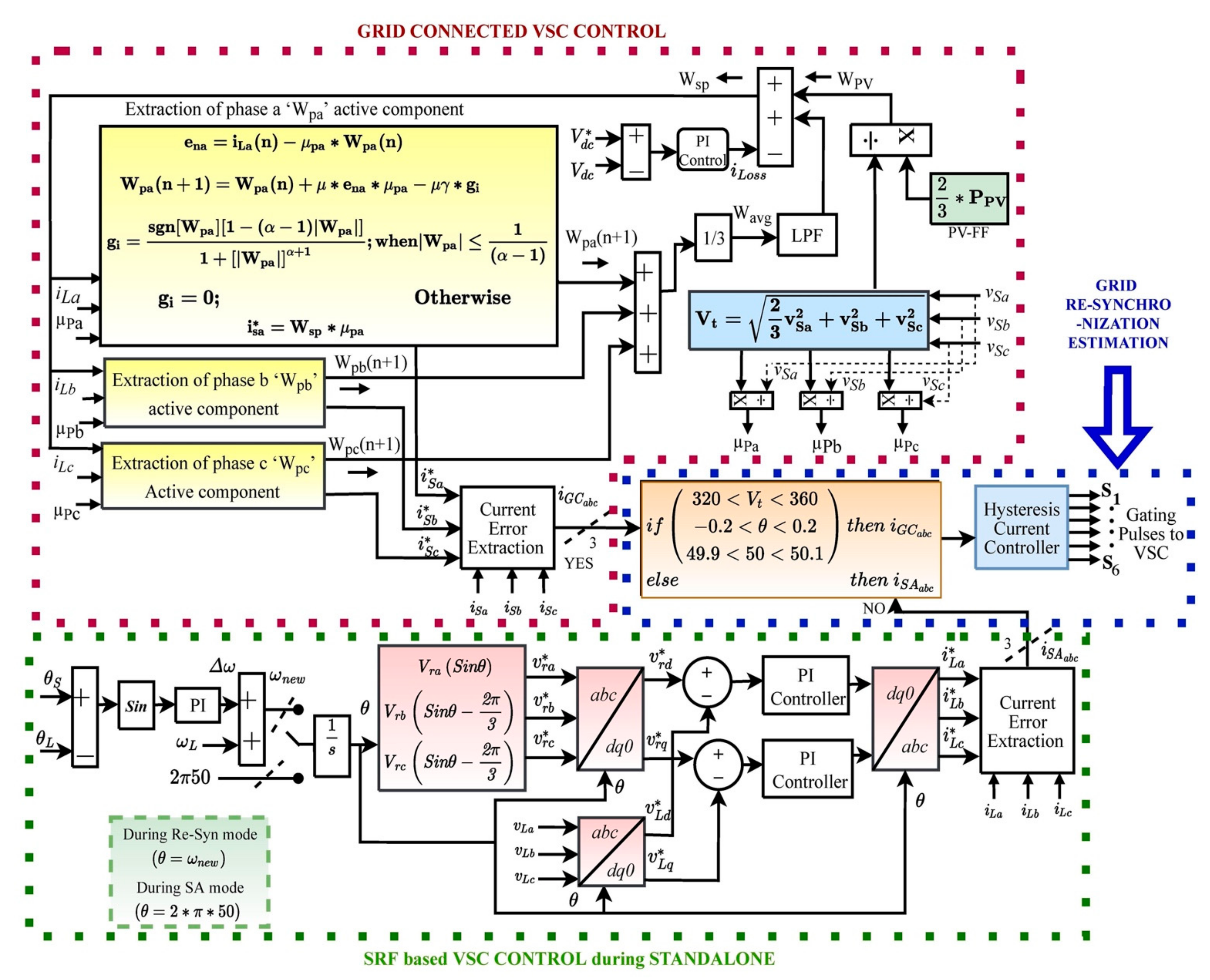
4.3. PZA-LMS Based VSC Control during GC Mode

Figure 5 shows the PZA-LMS-based VSC control for the GC mode. The system identification of sparse networks performed by PZA-LMS algorithm-based VSC control is crucial for detecting and filtrating impulse noises. The ZA feature detects the near-zero coefficient and considers their weights (without significantly changing their magnitude) during system identification.
The overall objective function of PZA-LMS is obtained as:
W p x n + 1 = W p x n μ ξ l 2 n W p x n μ γ ξ l 0 n W p x n ;   ( where   x = a ,   b ,   c )
ξ l 2 n W p x n = e n x n × μ p x ;   ( where   x = a ,   b ,   c )   and
ξ l 0 n W p x n = g p x n = s g n W p x n 1 α 1 W p x n 1 + W p x n α + 1 ; W p x n 1 α 1 0 ;   O t h e r w i s e
Here, PZA-LMS is implemented for the extraction of fundamental load current components. Each phase error signal is generated as a function of load currents i L a b c in phase unit templates μ p a , μ p b   , μ p c and overall weight component W sp as:
e n x = i L x µ p x × W s p ; where   x = a , b , c
The in-phase current components μ p a , μ p b   , μ p c are generated as a function of each phase grid voltage component v S a , v S b , v S c and V t as:
μ p x = v S x V t = v S x 2 3 v S a 2 + v S b 2 + v S c 2 ; where   x = a , b , c
Each phase’s weight components are calculated as:
W p a n + 1 = W p a n + μ × μ p a × e na n μ × γ × g pa n
g p a n = s g n W p a n 1 α 1 W p a n 1 + W p a n α + 1 ; W p a n 1 α 1 0 ;   O t h e r w i s e
W p b n + 1 = W p b n + μ × μ p b × e nb n μ × γ × g pb n
g p b n = s g n W p b n 1 α 1 W p b n 1 + W p b n α + 1 ; W p b n 1 α 1 0 ;   O t h e r w i s e
W p c n + 1 = W p c n + μ × μ p c × e nc n μ × γ × g pc n
g p c n = s g n W p c n 1 α 1 W p c n 1 + W p c n α + 1 ; W p c n 1 α 1 0 ;   O t h e r w i s e
Here, α is the polynomial term inversely proportional to the zero-attracting term. The average weight component, feed-forward, and DC loss current components terms are calculated as:
W avg = 1 3 W p a + W p b + W p c
Wpv = 2 3 V PV × I PV V t
i L o s s n + 1 = i L o s s n + k p V dc * V dc + k i / s V dc * V dc
The W sp is the overall weight generated as a function of W avg , W pv , and loss component of current i L o s s as:
W sp = W avg W pv + i L o s s
The reference signals i s a * , i s b * ,   and   i s c * during the GC mode are generated as:
i s a * = W s p × µ p a ,   i s b * = W s p × µ p b , i s c * = W s p × µ p c ,
The reference currents are delivered to the hysteresis current controller (HCC) for the switching signal generation.

4.4. SRF Based VSC Control during SA Mode

Figure 4 shows the VSC control during standalone operation, where the reference load voltages are converted into a dq0 frame using Park’s transformation as:
v r d * v r q * v r 0 * = 2 3 c o s θ s i n θ 1 2 c o s θ 2 π 3 s i n θ 2 π 3 1 2 c o s θ + 2 π 3 s i n θ + 2 π 3 1 2 × v r a * v r b * v r c *
The reference voltages v r d q 0 * are compared with the load voltage v L d q 0 * and further converted into the reference current signals i L a b c * with the help of phase-locked loop for the SA mode control.

4.5. Islanding and Re-Synchronization Control of VSC Control

When the grid is about to re-synchronize, the resynchronization control tries to match the load and grid voltages phases, and it further develops the v r a b c * signal. Before confirming re-synchronization, the voltage magnitude, phase angle and frequency of the incoming grid and SA system are matched. The system is observed during islanding, and re-synchronization is confirmed within 3–4 cycles.

5. Results and Discussion

The presented system was studied under (1) the GC mode during steady-state, irradiation variations, and load unbalancing; (2) the SA mode during steady-state and irradiation variation with derated InC MPPT; and (3) islanding and re-synchronization.

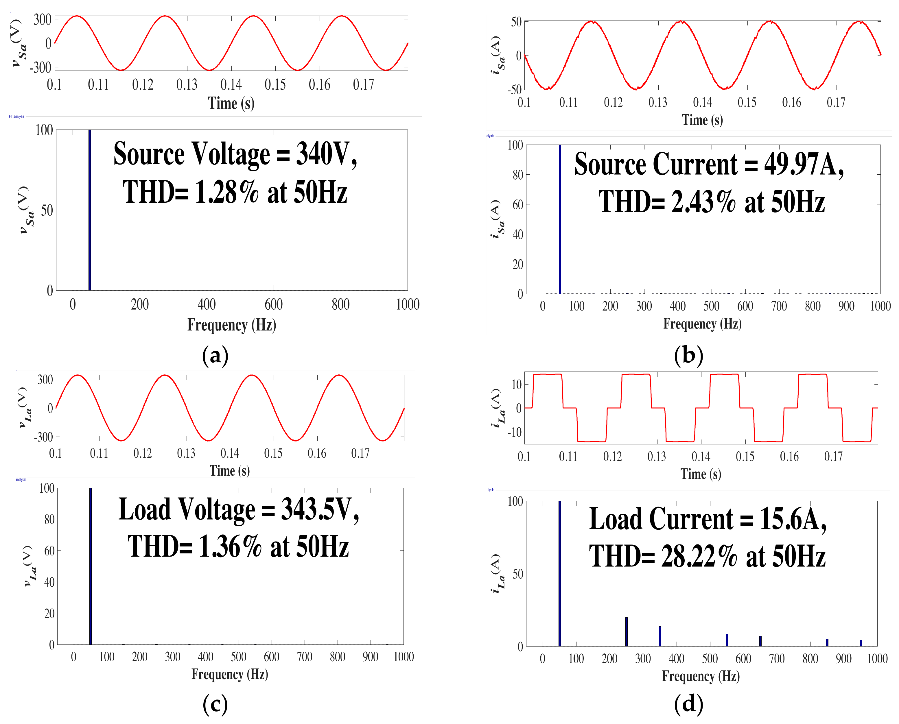
5.1. Steady-State Analysis during GC Mode

The steady-state performance was analyzed under a fixed irradiation level of 1000 W/m2. Figure 6a–d shows the total harmonics distortion (THD) analysis of the grid and load side, i.e., v S a , i S a , v L a and i L a . The grid THD levels were maintained well below 5% limit as per the IEEE 519 standard with non-linear load attached to the PCC. The THD results confirm that the PZA-LMS-algorithm-based VSC control effectively executed harmonics elimination at the PCC. The load’s current THD levels were at 28.22%.

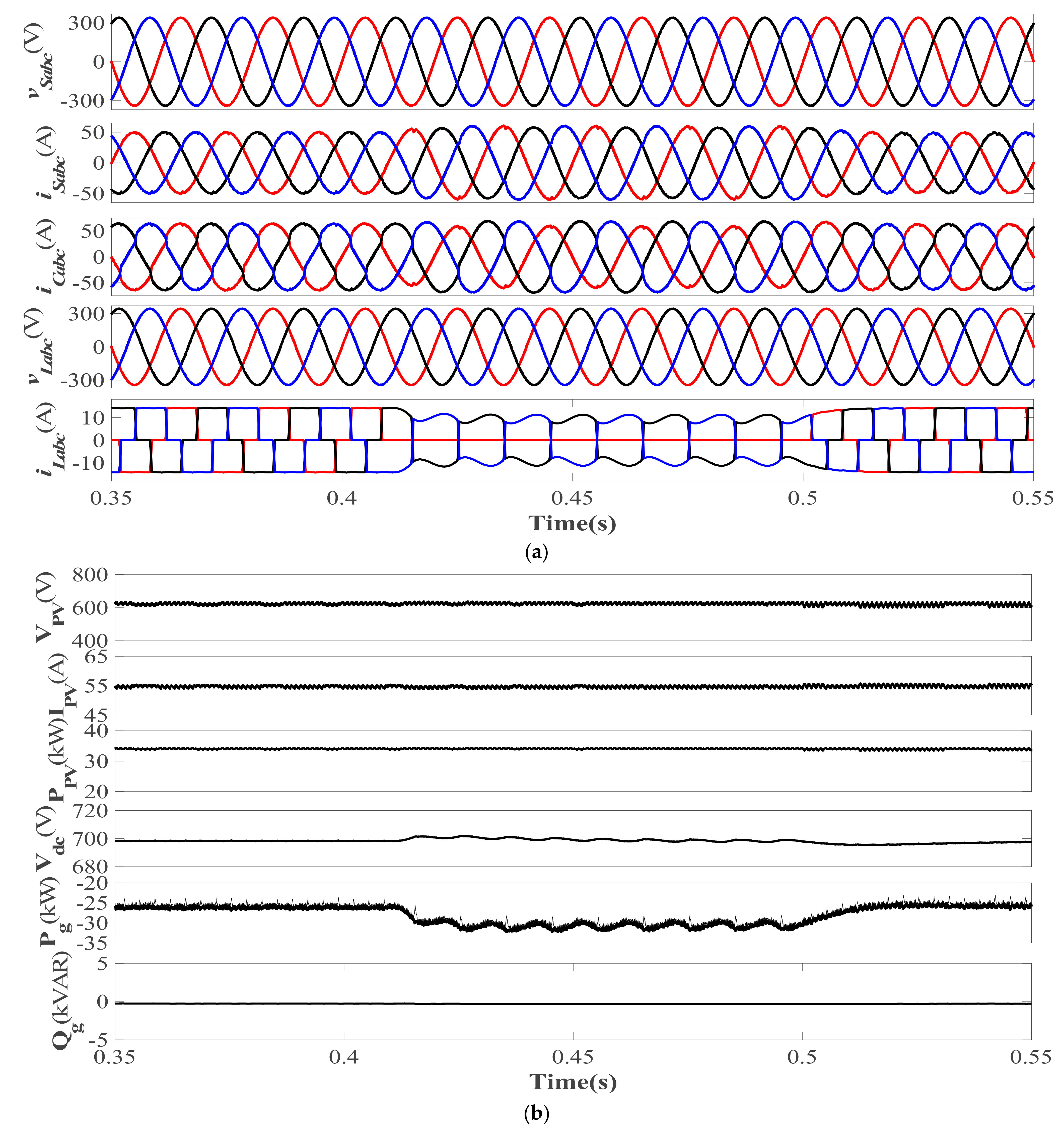
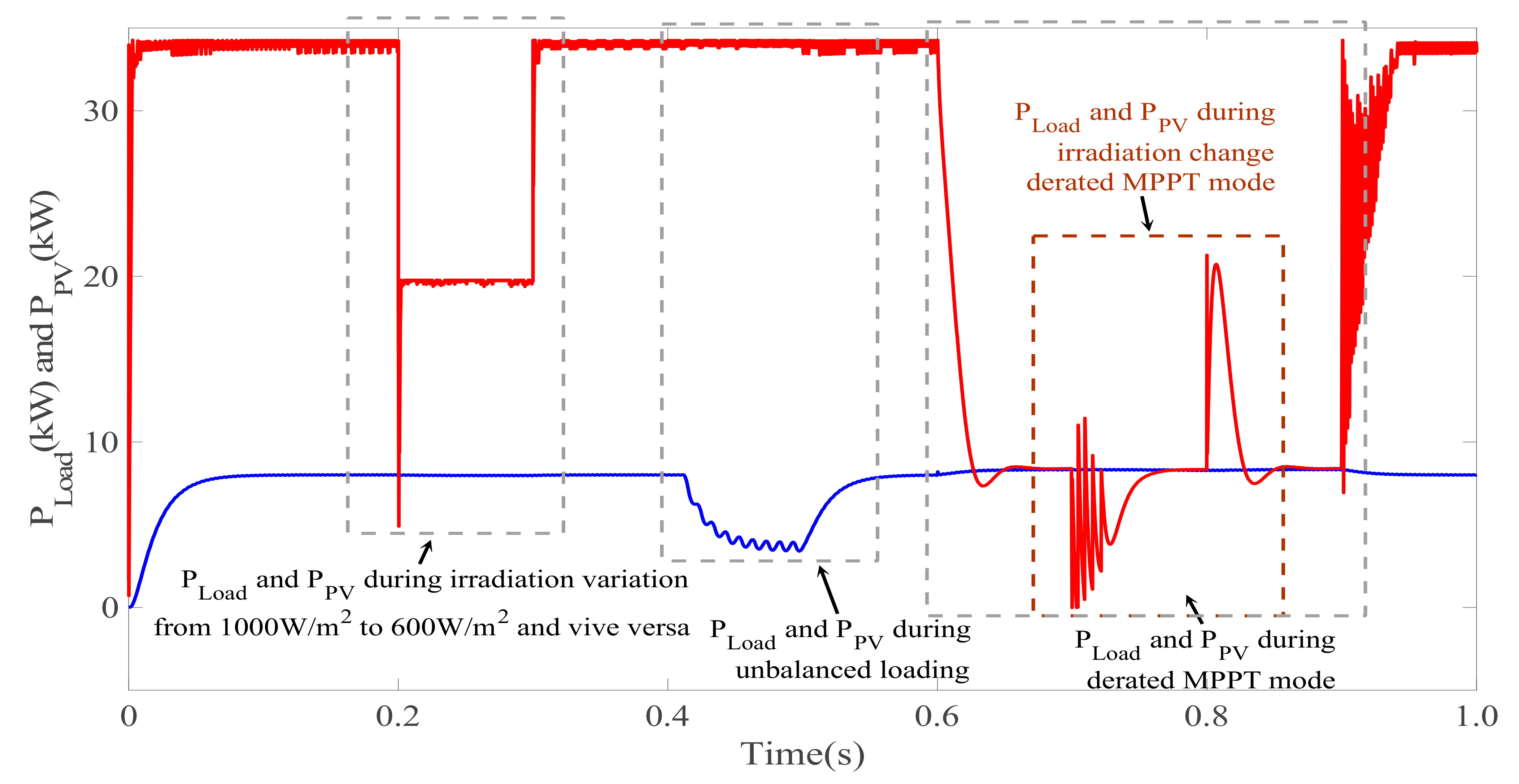
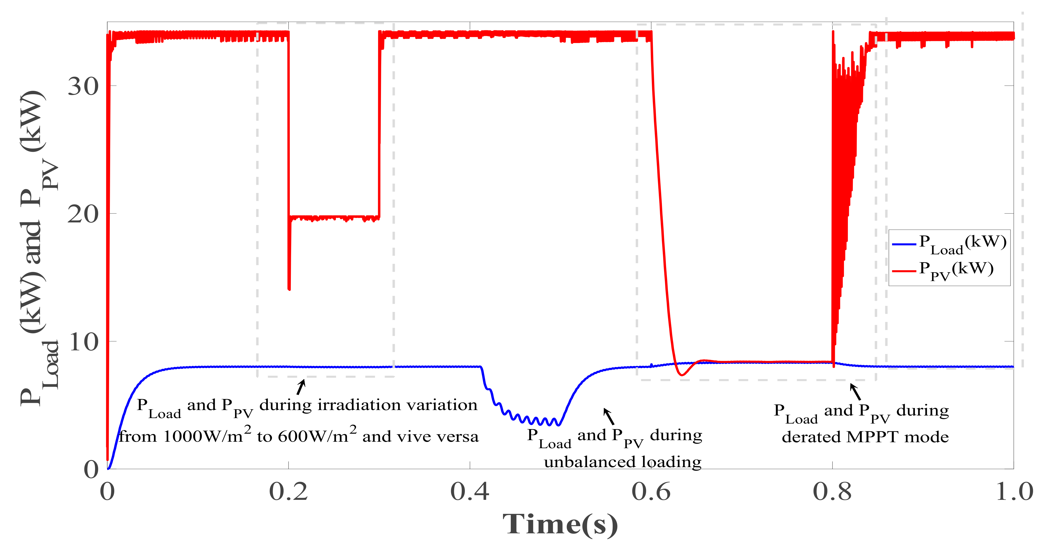
5.2. Irradiation Variation Analysis during GC Mode

Figure 7a,b shows the irradiation variation analysis of the system during the GC mode, when the solar insolation level was reduced from 1000 W/m2 to 600 W/m2 and vice versa. Figure 7a shows that the grid voltage and currents ( v s a b c and i s a b c ,   respectively ) in phase opposition as excess PV power was provided to the grid P g through the PCC. As the irradiation level was reduced, P g was also reduced, resulting in the reduced magnitude of i S a b c as well. The VSC current ( i C a b c ) magnitude was also reduced as the VSC handled less power. The load current ( i L a b c ) was distorted due to the non-linear load attached to the PCC. The magnitude of load voltage ( v L a b c ) remained the same as grid voltage during the GC mode. Figure 7b shows that the PV current and power ( I PV and P PV , respectively) reduces with solar irradiation levels. The V dc was maintained at the desired level. Moreover, the reactive power Q g exchange with the grid remained almost zero as VSC delivered the required Q g to the load.

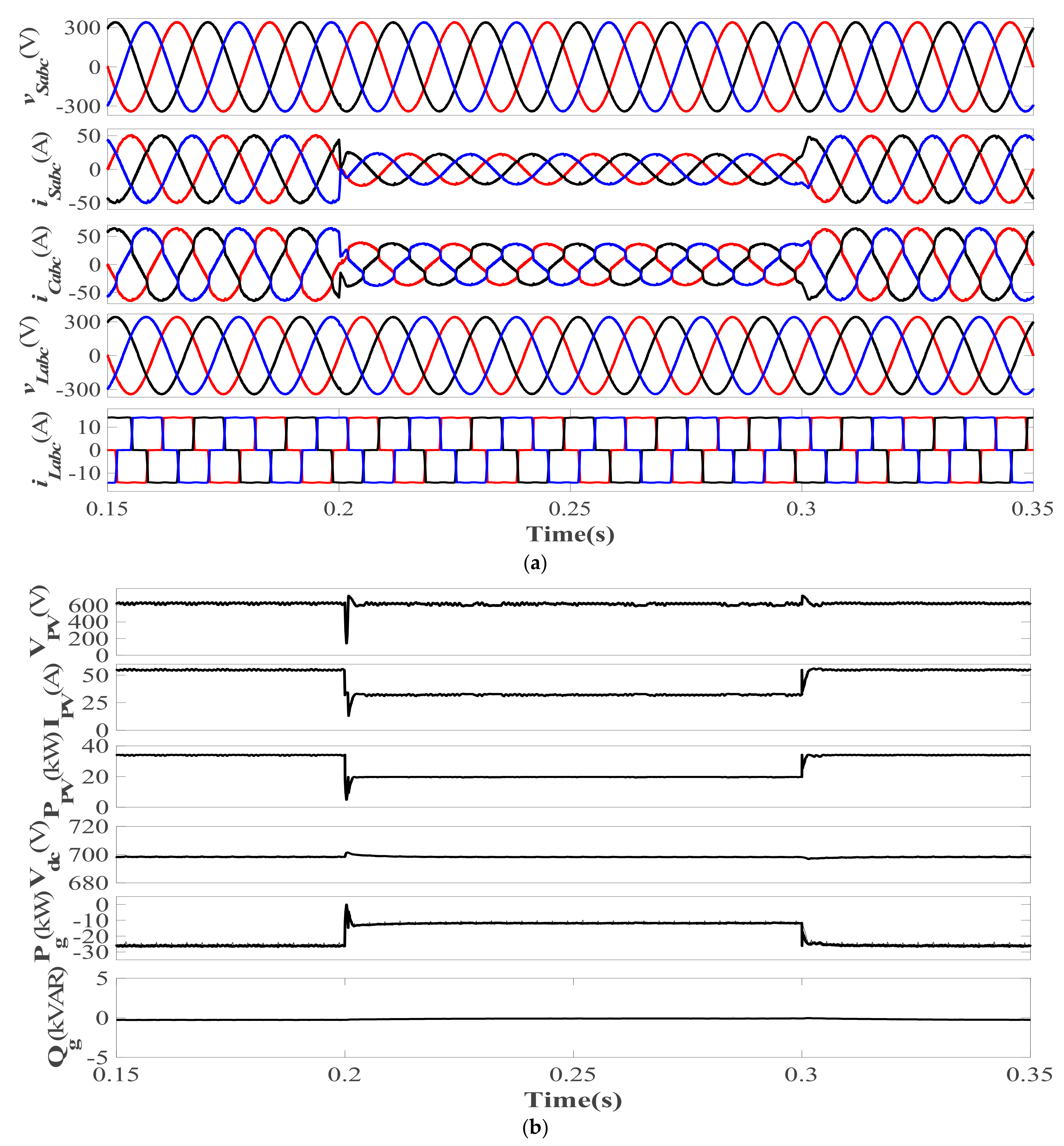
5.3. Load Unbalancing Analysis during GC Mode

Figure 8a,b shows the load unbalancing analysis during the GC mode, when the solar insolation level was kept fixed at 1000 W/m2. Figure 8a shows that v s a b c and i s a b c were 180 0 out of phase as P g was delivered to the grid. With unbalanced loading, phase ‘a’ of the grid became disconnected from the system. The unbalanced load demand was reduced to 66% of its balanced demand as only two phases remained connected to the grid, indicating the reduced load demand. The P g magnitude increased (became more negative) and there increased the i s a b c magnitude. Figure 8b shows that V PV ,   I PV and P PV remained unaffected. The V dc maintained its required voltage level. The Q g exchange with the grid also remained zero.

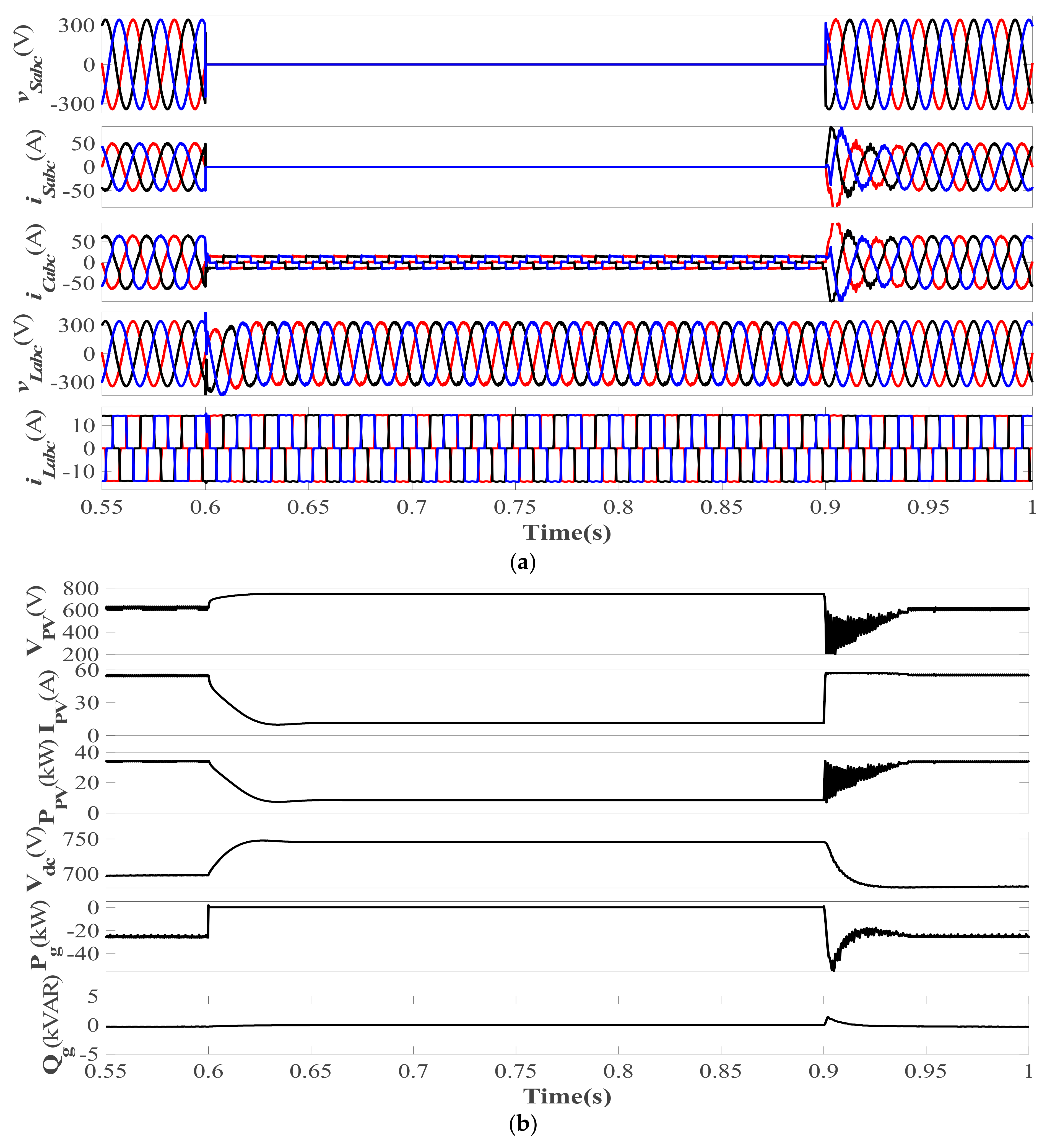
5.4. Islanding and Re-Synchronization Analysis

Figure 9a,b shows the islanding and re-synchronization operation when the grid was intentionally islanded with the help of a three-phase MCS switch. Figure 9a shows that the v s a b c became zero with grid islanding, also making the i s a b c zero. The i C a b c magnitude was drastically reduced as VSC only had to manage load demand. During the SA mode, the v L a b c maintained its sinusoidal nature and desired magnitude with the help of the SRF-based voltage control of the VSC. Figure 9b shows the SA operation, when InC MPPT operated in the derated mode. The I P V and P P V were significantly reduced due to the derated mppt as only load demand has to be fulfilled by the PV system. The V d c in the SA mode was also controlled by derated InC MPPT, stabilizing the system only according to the load demand. The P g and Q g exchange with the grid became zero in the SA mode.

5.5. Derated InC MPPT Operation Analysis in SA Mode

During the SA mode, the derated InC MPPT controls the DC bus and tries to extract only that much power, which is much needed by the load itself. The PV generation must match the load demand in the SA mode to verify the excess PV power curtailment. As shown in Figure 10, the SA mode was simulated for 0.6–0.8 s. During the GC mode, InC MPPT extracted maximum power from the PV system, whereas during the SA mode, P P V perfectly matched with P L o a d , accruing the excess PV power curtailment and reducing the need for a costly BSS.

5.6. Steady-State Analysis during SA Mode

Figure 11a,b shows the THD analysis of the load side during the SA mode. The SRF-based voltage control also performed the harmonics elimination, and the v L a THD level was maintained below 5% as per the IEEE 519 standard, whereas the i L a THD levels were very high due to the non-linearity of the load attached to the PCC.

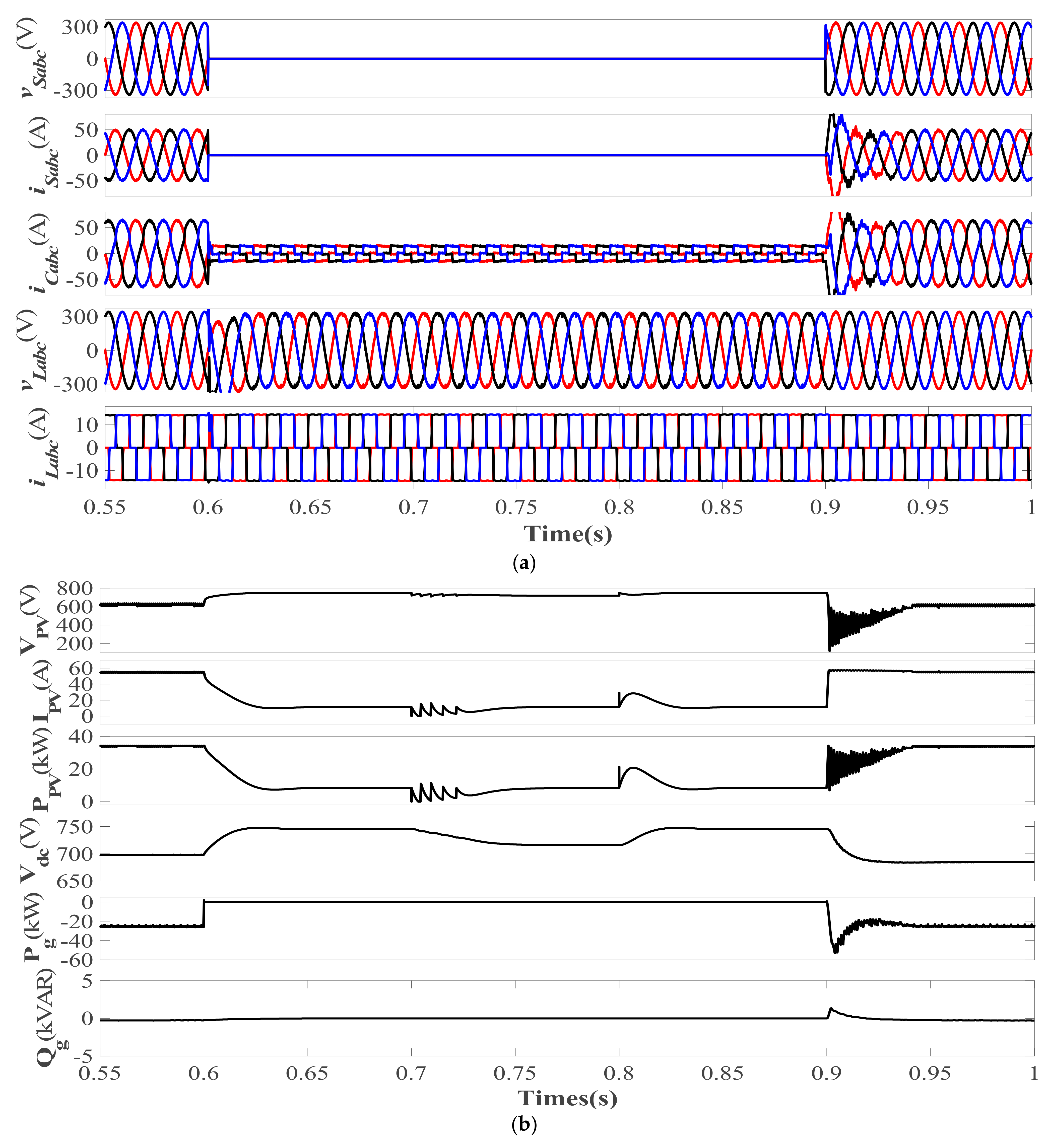
5.7. Irradiation Variation Analysis during SA Mode

Figure 12a,b shows the system’s performance during irradiation change from 1000 W/m2 to 600 W/m2 during the SA mode, when the derated InC MPPT algorithm controlled the DC bus. Figure 12a shows that the v L a b c was maintained at the desired level during islanded operation. Figure 12b shows the effect of irradiation change during the SA mode on I PV and P PV . The I PV and P PV showed minor variations with solar insolation changes. The V dc variations were prominent because derated InC MPPT controlled the DC bus and maintained the system’s stability.
Figure 13 shows the derated InC MPPT performance during irradiation variation in the SA mode from 0.7 s to 0.8 s of simulation time, when derated MPPT tried to deliver fixed power to the load P PV varies but due to irradiation change in the SA mode.

6. Conclusions

A 3P–3W, seamless, capable PV generation system without a BSS was presented for rural electrification in this study. The seamless capability allows the system to operate with and without grid supply, which is achieved via the effortless transition of VSC control from PZA-LMS-based current control during the GC mode to SRF-based voltage control during the SA mode without any transients on the grid and load side. The cost of a BSS is directly incurred by an end consumer without any government subsidies, which increases the overall cost of PV power generation and payback time, reducing the viability of a PV power generation system in a rural area. The presented system without a BSS was able to supply a local load during the daytime with the help of derated InC MPPT. During the GC mode, InC MPPT extracts maximum power from PV arrays and delivers it to the grid. In the SA mode, derated InC MPPT performs excess PV power curtailment by controlling the boost converter to meet the load demand in the absence of a BSS. During both the GC and SA modes, the presented system performs multifunctional operations, i.e., harmonics suppression, load balancing, power quality enhancements during weak grid conditions, and active and reactive power balancing at the PCC. The multifunctional operations occur during steady-state and diverse dynamic states, i.e., irradiation variation, unbalanced loading, and islanding and re-synchronization. The presented system was shown to be able to maintain grid THD below 5% and re-synchronize the system with the grid utility in less than 10 cycles, satisfactorily performing as per the IEEE 519 and IEEE 1547 standards.

Author Contributions

The presented work was developed by the following contributions: Conceptualization, M.C., I.H., A.A., H.M., F.P.G.M. and M.A.A.; methodology, M.C., I.H., A.A., H.M. and M.A.A.; software, F.P.G.M., M.C., I.H., A.A., H.M. and M.A.A.; validation, M.C., I.H., A.A., H.M. and M.A.A.; formal analysis, F.P.G.M., M.C., I.H., A.A., H.M. and M.A.A.; investigation, M.C., I.H., A.A., H.M. and M.A.A.; resources, F.P.G.M., M.C., I.H., A.A., H.M. and M.A.A.; data curation, M.C., I.H., A.A., H.M. and M.A.A.; writing—original draft preparation, M.C., I.H., A.A., H.M.; F.P.G.M. and M.A.A.; writing—review and editing, M.C., I.H., A.A., H.M., F.P.G.M. and M.A.A.; visualization, M.C., I.H., A.A., H.M. and M.A.A.; supervision, F.P.G.M. and M.A.A.; project administration, H.M. and M.A.A.; funding acquisition, H.M. and M.A.A. All authors have read and agreed to the published version of the manuscript.

Funding

The authors extend their appreciation to the Researchers Supporting Project at King Saud University, Riyadh, Saudi Arabia, for funding this research work through the project number RSP-2021/278. The authors would like to acknowledge the support from Intelligent Prognostic Private Limited Delhi, India Researcher’s Supporting Project.

Institutional Review Board Statement

Not applicable.

Informed Consent Statement

Not applicable.

Data Availability Statement

Not applicable.

Acknowledgments

The authors would like to acknowledge the support from Universiti Teknologi Malaysia (UTM), Johor Bahru 81310, Malaysia; support from Ingenium Research Group, Universidad Castilla-La Mancha, 13071 Ciudad Real, Spain; support from King Saud University, Saudi Arabia; and support from Intelligent Prognostic Private Limited Delhi, India Researcher’s Supporting Project.

Conflicts of Interest

The authors declare no conflict of interest.

Nomenclature

μ p x   x = a : b , c In-phase components
V t Voltage magnitude (V)
I PV PV Current (A)
V PV PV Voltage (V)
P PV PV Power (kW)
D GC Grid-Connected Duty Cycle
V dc DC Bus Voltage (V)
P Load Load Demand (kW)
D derated Derated Duty Cycle
D SA Standalone Duty Cycle
V MPP Voltage at MPP (V)
I MPP Current at MPP (A)
e n x   x = a , b , c Error signals
v S a b c Source voltage (V)
i S a b c Source current (A)
v L a b c Load voltage (V)
i L a b c Load current (A)
W p x   x = a , b , c Each phase’s Weight signals
μ Step Size
W pv Feed-forward term
W avg Average weight signals
W sp Overall weight
i S x * x = a , b , c Reference source current (A)
v r d q o * Reference Load Voltages in dq0 frame (V)
v L d q o * Load Voltages in dq0 frame (V)
i L a b c * Reference Load Currents (A)
i C a b c Compensator Currents (A)
P g Active Power delivered to Grid (kW)
Q g Reactive Power delivered to Grid (kVAR)
3P–3WThree-phase three-wire
GCGrid-Connected
SAStandalone
VSCVoltage source converter
LMSLeast Mean Square
PZA-LMSPolynomial Zero-Attracting LMS
PCCPoint of Common Coupling
InCIncremental conductance
MPPTMaximum Power Point Tracking
MPPMaximum Power Point
SRFSynchronous Reference Frame
BSSBattery Storage System
THDTotal Harmonics Distortion
RESsRenewable Energy Systems
DGDistributed Generators
MPEMaximum Power Extraction
P&OPerturb and Observe
MPPMaximum Power Point
LMFLeast Mean Fourth
HC-LMSHyperbolic LMS
VSS-LMSVariable Step-Size LMS
MCCMaximum Correntropy Criteria
RZA-LMSResized Zero-Attracting LMS
MCSMaster Control Switch
PIProportional Integral

References

  1. Ines Come Zebra, E.; van der Windt, H.J.; Nhumaio, G.; Faaji, A.P.C. A Review of Hybrid Renewable Energy Systems in Mini-Grids for off-Grid Electrification in Developing Countries United States Agency for International Development. Renew. Sustain. Energy Rev. 2021, 144, 111036. [Google Scholar] [CrossRef]
  2. Smirnova, E.; Kot, S.; Kolpak, E.; Shestak, V. Governmental Support and Renewable Energy Production: A Cross-Country Review. Energy 2021, 230, 120903. [Google Scholar] [CrossRef]
  3. Bhamu, S.; Bhatti, T.S.; Pathak, N. Modelling and Dynamic Stability Study of Interconnected System of Renewable Energy Sources and Grid for Rural Electrification. Int. J. Emerg. Electr. Power Syst. 2019, 20, 1–14. [Google Scholar] [CrossRef]
  4. Naqvi, S.B.Q.; Singh, B. A PV-Battery System Resilient to Weak Grid Conditions with Regulated Power Injection and Grid Supportive Features. IEEE Trans. Sustain. Energy 2022, 13, 1408–1419. [Google Scholar] [CrossRef]
  5. Chong, L.W.; Wong, Y.W.; Rajkumar, R.K.; Isa, D. Modelling and Simulation of Standalone PV Systems with Battery-Supercapacitor Hybrid Energy Storage System for a Rural Household. Energy Procedia 2017, 107, 232–236. [Google Scholar] [CrossRef]
  6. Zarina, P.P.; Mishra, S. Cost Benefit of Using Deloaded PV Instead of Battery. In Proceedings of the IEEE International Conference on Power Electronics, Drives and Energy Systems, 2016 IEEE International Conference on Power Electronics, Drives and Energy Systems (PEDES), Trivandrum, India, 14–17 December 2016. pp. 1–4. [CrossRef]
  7. Velasco De La Fuente, D.; Trujillo Rodríguez, C.L.; Garcerá, G.; Figueres, E.; Ortega Gonzalez, R. Photovoltaic Power System with Battery Backup with Grid-Connection and Islanded Operation Capabilities. IEEE Trans. Ind. Electron. 2013, 60, 1571–1581. [Google Scholar] [CrossRef]
  8. Zhu, Y.L.; Yao, J.G.; Wu, D. Comparative Study of Two Stages and Single Stage Topologies for Grid-Tie Photovoltaic Generation by PSCAD/EMTDC. In Proceedings of the 2011 International Conference on Advanced Power System Automation and Protection, Beijing, China, 16–20 October 2011; Volume 2, pp. 1304–1309. [Google Scholar] [CrossRef]
  9. Srinivas, V.L.; Singh, B.; Mishra, S. Fault Ride-Through Strategy for Two-Stage Grid-Connected Photovoltaic System Enabling Load Compensation Capabilities. IEEE Trans. Ind. Electron. 2019, 66, 8913–8924. [Google Scholar] [CrossRef]
  10. Kumar, V.; Singh, M. Derated Mode of Power Generation in PV System Using Modified Perturb and Observe MPPT Algorithm. J. Mod. Power Syst. Clean Energy 2021, 9, 1183–1192. [Google Scholar] [CrossRef]
  11. Sahoo, S.; Mishra, S.; Jha, S.; Singh, B. A Cooperative Adaptive Droop Based Energy Management and Optimal Voltage Regulation Scheme for DC Microgrids. IEEE Trans. Ind. Electron. 2020, 67, 2894–2904. [Google Scholar] [CrossRef]
  12. Alam, M.J.E.; Muttaqi, K.M.; Sutanto, D. Mitigation of Rooftop Solar PV Impacts and Evening Peak Support by Managing Available Capacity of Distributed Energy Storage Systems. IEEE Trans. Power Syst. 2013, 28, 3874–3884. [Google Scholar] [CrossRef] [Green Version]
  13. Mao, M.; Cui, L.; Zhang, Q.; Guo, K.; Zhou, L.; Huang, H. Classification and Summarization of Solar Photovoltaic MPPT Techniques: A Review Based on Traditional and Intelligent Control Strategies. Energy Rep. 2020, 6, 1312–1327. [Google Scholar] [CrossRef]
  14. Motahhir, S.; el Hammoumi, A.; el Ghzizal, A. The Most Used MPPT Algorithms: Review and the Suitable Low-Cost Embedded Board for Each Algorithm. J. Clean. Prod. 2020, 246, 118983. [Google Scholar] [CrossRef]
  15. Karami, N.; Moubayed, N.; Outbib, R. General Review and Classification of Different MPPT Techniques. Renew. Sustain. Energy Rev. 2017, 68, 1–18. [Google Scholar] [CrossRef]
  16. Villegas-Mier, C.G.; Rodriguez-Resendiz, J.; Álvarez-Alvarado, J.M.; Rodriguez-Resendiz, H.; Herrera-Navarro, A.M.; Rodríguez-Abreo, O. Artificial Neural Networks in Mppt Algorithms for Optimization of Photovoltaic Power Systems: A Review. Micromachines 2021, 12, 1260. [Google Scholar] [CrossRef] [PubMed]
  17. Zarina, P.P.; Mishra, S. Power Oscillation Reduction Contribution by PV in Deloaded Mode. In Proceedings of the 2016 IEEE 6th International Conference on Power Systems (ICPS), New Delhi, India, 4–6 March 2016; pp. 128–131. [Google Scholar] [CrossRef]
  18. Kumar, V.; Singh, M. Reactive Power Compensation Using Derated Power Generation Mode of Modified P&O Algorithm in Grid-Interfaced PV System. Renew. Energy 2021, 178, 108–117. [Google Scholar] [CrossRef]
  19. Liu, H.; Zhang, W.; Sun, B.; Member, S.; Loh, P.C.; Wang, W.; Xu, D.; Blaabjerg, F. Seamless Transfer Scheme with Unified Control Core for Paralleled Systems. IEEE Trans. Power Electron. 2019, 34, 6286–6298. [Google Scholar] [CrossRef]
  20. Naqvi, S.B.Q.; Kumar, S.; Singh, B. Three-Phase Four-Wire PV System for Grid Interconnection at Weak Grid Conditions. IEEE Trans. Ind. Appl. 2020, 56, 7077–7087. [Google Scholar] [CrossRef]
  21. Zhang, Q.; Mao, M.; Ke, G.; Zhou, L.; Xie, B. Stability Problems of PV Inverter in Weak Grid: A Review. IET Power Electron. 2020, 13, 2165–2174. [Google Scholar] [CrossRef]
  22. Chankaya, M.; Hussain, I.; Ahmad, A.; Malik, H.; García Márquez, F.P.; Márquez, F.P.G. Generalized Normal Distribution Algorithm-Based Control of 3-Phase 4-Wire Grid-Tied PV-Hybrid Energy Storage System. Energies 2021, 14, 4355. [Google Scholar] [CrossRef]
  23. Chankaya, M.; Hussain, I.; Ahmad, A.; Malik, H.; García Márquez, F.P. Multi-Objective Grasshopper Optimization Based MPPT and VSC Control of Grid-Tied PV-Battery System. Electronics 2021, 10, 2770. [Google Scholar] [CrossRef]
  24. Bhattacharjee, S.S.; Ray, D.; George, N.V. Adaptive Modified Versoria Zero Attraction Least Mean Square Algorithms. IEEE Trans. Circuits Syst. II Express Briefs 2020, 67, 3602–3606. [Google Scholar] [CrossRef]
  25. Maheshwari, J.; George, N.V. Polynomial Sparse Adaptive Algorithm. Electron. Lett. 2016, 52, 2063–2065. [Google Scholar] [CrossRef]
  26. Chankaya, M.; Ahmad, A.; Hussain, I. Path-Finder Optimization Based Control of Grid-Tied PV Hybrid Energy Storage System. IETE J. Res. 2021, 1–18. [Google Scholar] [CrossRef]
Figure 1. Proposed topology.
Electronics 11 02413 g001
Figure 2. Research methodology.
Electronics 11 02413 g002
Figure 3. Boost converter control during SA mode.
Electronics 11 02413 g003
Figure 4. Derated operation of InC MPPT during SA mode.
Electronics 11 02413 g004
Figure 5. PZA-LMS-based VSC control.
Electronics 11 02413 g005
Figure 6. (ad) THD analysis of v S a , i S a , v L a   and   i L a .
Electronics 11 02413 g006
Figure 7. Irradiation variation analysis during GC mode of (a) v s a b c , i s a b c , i C a b c , v L a b c ,   and   i L a b c ; (b) V PV , I PV , P PV ,   V dc ,   P g , and Q g .
Electronics 11 02413 g007
Figure 8. Load unbalancing analysis during GC mode of (a) v s a b c , i s a b c , i C a b c , v L a b c ,   and   i L a b c ; (b) V PV , I PV , P PV ,   V dc ,   P g , and Q g .
Electronics 11 02413 g008
Figure 9. Grid islanding and re-synchronization analysis of (a) v s a b c , i s a b c , i C a b c , v L a b c ,   and   i L a b c ; (b) V PV , I PV , P PV ,   V dc ,   P g , and Q g .
Electronics 11 02413 g009
Figure 10. Load and PV power variations with InC MPPT in GC mode and derated InC MPPT in SA mode.
Electronics 11 02413 g010
Figure 11. (a,b) THD analysis of v L a   and   i L a .
Electronics 11 02413 g011
Figure 12. Irradiation variation analysis during SA mode of (a) v s a b c , i s a b c , i C a b c , v L a b c ,   and   i L a b c ; (b) V PV , I PV , P PV ,   V dc ,   P g , and Q g .
Electronics 11 02413 g012
Figure 13. Load and PV power variations with InC MPPT in GC mode and derated InC MPPT in SA mode during irradiation variations.
Electronics 11 02413 g013
Publisher’s Note: MDPI stays neutral with regard to jurisdictional claims in published maps and institutional affiliations.

