1. Introduction
With the continuous increase of data and devices in wireless networks, existing wireless networks face difficulty in increasing traffic load. Consequently, the next generation of mobile cellular communication and networking has emerged [
1].
At the same time, global operators face many challenges in 5G network development, with insufficient coverage, difficult construction and high investment, and high operating expenses. By now, the global population using mobile services has reached 5.3 billion, accounting for 67% of the total global population. The number of 5G connections will increase from 8% of the total number of connections in 2021 to 25% in 2025, and it is expected that 5G connections will account for one-fourth of the total mobile connections in 2025. However, some developing regions and countries around the world still do not have mobile communication coverage. How to let more developing regions also enjoy mobile communications and experience the convenient life brought by 5G is a problem that the global communications industry needs to solve. In addition, operator revenue will increase from USD 1.08 trillion in 2021 to USD 1.16 trillion in 2025, and operator expenses are expected to reach USD 620 billion from 2022 to 2025, 85% of which will be spent on 5G development [
2]. In addition to the purchase of an expensive wireless spectrum, 5G construction uses higher frequency bands, greater bandwidth, higher base station construction densities, and higher power consumption and construction costs per station. How to reduce the cost of 5G network construction and operation is a common and urgent problem for global operators.
5G wireless network sharing can effectively improve the utilization of spectrum resources, rapidly form advanced mobile networks, accelerate infrastructure networks, and promote the development of the digital economy [
3]. Wireless network sharing has a long history, and since the 3G era, some European operators proposed demands for mobile communication network sharing. Network sharing among global operators has been occurring, and various forms of sharing have emerged [
4,
5,
6]. The 3rd-Generation Partnership Project (3GPP) first developed the 3G network sharing standard in Release 6 [
7]. TS 23.251 defines the Multi-Operator Core Network (MOCN) network-sharing architecture, including basic functions such as system information broadcast and network selection as well as basic requirements for UE, base station, core network, and other devices to support network sharing [
7], Ref. [
8] and others define interface protocols to support related network sharing requirements. 3GPP successively clarified the 4G and 2G network-sharing specifications in Release 8 and Release 10. Release 15 started to support 5G MOCN radio access network sharing and standardized radio access network sharing in terms of network architecture, air interface, NG interface, and XN interface protocols. Ref. [
9] defines the MOCN sharing architecture under 5G stand-alone (SA) networking. With the new demand for network sharing, 3GPP standards continue to evolve, and new radio (NR) networks can evolve from non-stand-alone (NSA) networks to SA networks. The system model figure and specific solutions for 5G access network sharing are described in
Section 3.
The IP multimedia subsystem (IMS) is an all-IP system designed to assist mobile operators to deliver next-generation interactive and interoperable services over an architecture providing the flexibility of the Internet [
10]. Voice is a real-time service with tight delay requirements; thus, it requires a robust underlying radio network to ensure an optimal user experience [
11]. 3GPP has adopted GSMA IR.92 IMS profile for voice and SMS [
12] and GSMA IR.94 IMS profile for conversational video [
13] to provide high-quality IMS-based voice services over NR radio access. 3GPP Release15 has provided voice services for 5G users based on IMS. IMS-based voice over new radio (VoNR), as the target voice solution for operators, can fully utilize the advantages of high spectrum utilization, fade resistance, high bandwidth, and high capacity of 5G wireless technology. It provides users with shorter voice access latency and an ultra-high definition communication experience [
14]. VoNR is the target voice solution for 5G networks [
15].
However, in the early stage of network construction, constrained by the low penetration of 5G UE, insufficient network coverage, and the long-term coexistence of 4G and 5G, the premature scale deployment of VoNR will bring frequent 4/5G handover. Handover is the basis for service continuity in mobile networks, supporting the movement of UE between different base stations or access points (AP) provided with multiple access technologies [
16]. The frequent handover will increase delay and affect user experience. In the last decade, many investigations on handover cases have also been conducted. According to the studies, refs. [
17,
18,
19] focus on handover efficiency. Ref. [
20] focuses on handover tools and architectures. However, there is no research analyzed so far for the voice handover performance of 5G network-sharing architecture under different evolutionary stages.
Frequent handover increases time delay and introduces user security issues that affect the user experience. The related state-of-the-art communication and data-sharing security studies are analyzed in [
21,
22,
23]. This paper focuses on the time delay caused by handover. In different stages of 5G evolution, with different network structures and deployment scales, how to develop 5G voice solutions that meet the network deployment route and improve call quality is one of the important issues that urgently need to be solved.
In the 5G NSA deployment phase, long-term evolution (LTE) and NR are used in dual-connection mode. 5G NR is added to the existing 4G network as a capacity extension. Following the 4G EPC, the 4G network remains the primary control network. 5G NR supports only best-effort data transmission. Voice is guaranteed service continuity via voice over long-term evolution (VoLTE). The performance of VoLTE was studied in [
24].
When evolving to 5G SA network sharing initially without VoNR feature, voice services can be a fallback to 4G LTE network with the help of EPS fallback as a temporary transition solution. Similar to CS fallback in the 4G era, under EPS fallback, the 5G NR network does not provide voice services [
25]. The handover/redirection is initiated by the 5G base station (gNodeB) to the 4G core network (EPC), and the UE falls back to the 4G network, where the delay will be increased.
As 5G SA networks mature, voice services can be carried by 5G with VoNR. All services are carried through the 5G network, but the voice needs to be controlled by IMS. Under VoNR, the UE resides in the 5G network, and both voice and data are carried in 5G. In poor-coverage areas of 5G signal, 4/5G handover-based interoperability can be achieved, and the LTE networks provide voice services. Similar to the single radio voice call continuity (SRVCC) of 4G, the VoNR also supports smooth handover between VoNR and VoLTE through the Inter-RAT handover mechanism [
26].
The remainder of the paper is organized as follows.
Section 2 introduces the motivation and contribution.
Section 3 investigates the technical details of the 5G access network-sharing solution. In
Section 4, the call setup flow of VoLTE under NSA sharing, EPS fallback, and VoNR under SA sharing are investigated.
Section 5 provides the experimental results and analysis of VoLTE, EPS fallback, and VoNR.
Section 6 summarizes the conclusion.
2. Motivation and Contribution
The focus of this study is the call setup delay and handover delay for VoLTE, EPS fallback, and VoNR performance in the 5G sharing network.
Global operators face many challenges in 5G network development, with insufficient coverage, difficult construction and high investment, and high operating expenses. Most operators worldwide are in the 5G NSA deployment phase right now [
27]. This study first proposes a sharing architecture for 5G access networks in response to the real problem of slow progress in 5G construction faced by global operators.
Regardless of which network configuration solutions, voice service demand is a key aspect of 5G network construction [
28]. Providing stable and high-quality voice services to users is an important part of the 5G experience. The performance of VoLTE, EPS fallback, and VoNR is the key issue to ensure a better voice experience in NR networks. The relevant parameters are given in [
29,
30]. However, the existing voice solutions research is only up to 4G networks, e.g., [
11]. 5G network-sharing studies are only limited to the architectural level, e.g., [
31]. There is no research yet on voice solutions for the full network evolution phase from NSA to SA for 5G sharing networks.
The contribution in this paper is in three-fold. Firstly, we present voice solutions for different 5G sharing network evolution stages, including VoLTE in the NSA stage, EPS fallback in SA early stage, and VoNR in SA mature stage. Secondly, the theoretical analysis of each involved solution is presented, giving the main concepts and their potential results for deployment in current 5G sharing networks. We compare and analyze the call setup time delay of three voice solutions. The handover process involved is highlighted. The call flow and relevant call setup KPIs are established and analyzed in detail for the redirection and handover strategies. Thirdly, this study performs practical verification and analysis by building test environments based on mainstream equipment vendors in the first actual commercial 5G sharing networks. The best practices and optimization techniques for VoLTE, EPS fallback, and VoNR are provided based on live network performance and the targeted end-user experience. This is also the first study of sharing voice solutions in different evolutionary stages of 5G in the world, analyzing and verifying from theoretical and experimental perspectives.
3. 5G Access Network Sharing
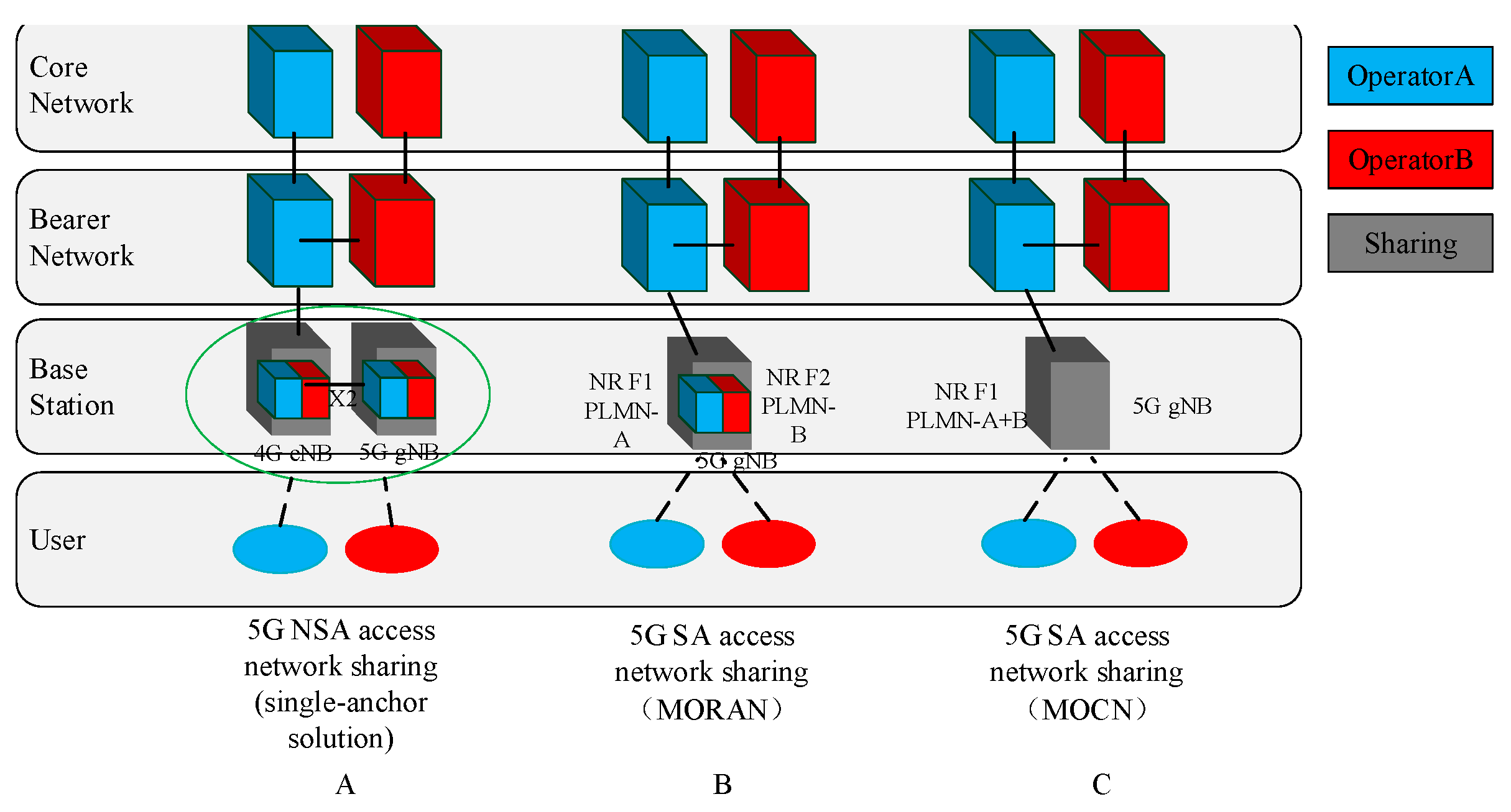
5G access network sharing can be divided into two schemes: multi-operator radio access network (MORAN) and MOCN. MORAN configures an independent carrier for each sharing operator, which broadcasts its respective network public land mobile network (PLMN) ID on the respective carrier. Each carrier is independently configured and managed. The gNodeB on the wireless side uses logically separate cells for users of operators. Users of each operator access their respective independent cells by identifying their respective PLMN. gNodeB connects users to their respective core networks based on their respective carriers, as shown in
Figure 1B. In studies of recent years, [
31] focuses on the architecture of 5G access network sharing; ref. [
32] focuses on data automatic configuration in 5G sharing networks; and ref. [
33] focuses on networking and multi-service bearer based on 5G sharing networks.
The MOCN configures one or more carriers to achieve frequency-resource sharing. MOCN realizes cell-level sharing with the same cell-level parameters. Multiple PLMNs are broadcast simultaneously within one cell. The base station connects the users to their respective core networks according to the PLMN information, as shown in
Figure 1C.
In the NSA sharing scheme, EPC and the 5G core network (5GC) are built separately. The two core networks are connected to the 5G NR stations and anchor 4G stations (eNodeB). Both gNodeB and anchor eNodeB need to be shared, as shown in
Figure 1A. Anchor points are configured independently using dual carriers. The user equipment (UE) should adopt the LTE-NR dual-connection and dual-registration strategy. Control plane anchoring and voice service bearing are dependent on 4G. The user plan bears on 4G or/and 5G. The enabled X2 interface between eNodeB and gNodeB is used for achieving user separation and interoperability.
NSA access network sharing can evolve to SA sharing. The SA access network-sharing architecture is shown in
Figure 1B,C. Only gNodeBs are required to connect to the 5GC of the sharer. The core network does not need to be modified. gNodeBs are enabled for base station sharing, and eNodeBs of each party are configured as neighbors. 5G network construction is decoupled from 4G. There is no need for various complex anchor collaboration schemes; thus, 4 and 5G do not affect the experience of each other.
4. Voice Services Based on 5G Sharing
5G voice continues the VoLTE feature IP-based solution. However, considering the complexity and authentication security issues of interoperability with other network standards, 3GPP defines 5G to only interoperate with 4G and no longer interact with 2G/3G. IMS is the foundation for 5G users to use voice communication services.
On the other hand, as mentioned above, compared to the 4G network scenario, 3GPP Release 15 defines two deployment options for 5G NR, SA, and NSA modes. Accordingly, the voice solution also needs to be selected based on the existing network architecture, and a suitable voice network construction plan needs to be developed based on the network scenario and network construction rhythm. Therefore, the paper gives an achievable evolutionary path, as shown in
Figure 2.
At the beginning of 5G, the voice and data networks are separated. Voice is provided through EPC + LTE with VoLTE. With the adoption of 5GC, voice services continue to be provided through EPC + LTE, with EPS fallback as the voice solution. Finally, after the 5G network is deeply optimized, the VoNR feature is gradually implemented.
Handover is involved regardless of the voice solutions. The process of handover based on service type is shown in
Figure 3.
In the process of handover, there will be a handover delay, which is the delay of the radio resource control (RRC) process plus the interrupt delay. The equation is:
The
is the RRC process delay, defined in Section 12 of TS 38.331 [
8], while the interrupt delay
is calculated as follows:
is the time required to search the target cell when the target cell is not already known when the handover command is received by the UE. If the target cell is known, then
= 0 ms. If the target cell is an unknown intra-frequency cell, and the target cell Es/Iot ≥ −2 dB, then
= Trs ms. If the target cell is an unknown inter-frequency cell, and the target cell Es/Iot ≥ −2 dB, then
= 3 * Trs ms. Regardless of whether DRX is in use by the UE,
shall still be based on non-DRX target cell search times.
is the interruption uncertainty in acquiring the first available physical random access channel (PRACH) occasion in the new cell.
can be up to the summation of static shared beam (SSB) to PRACH-occasion association period and 10 ms. SSB to PRACH occasion-associated period is defined in Table 8.1-1 of TS 38.213 [
34].
is time for UE processing.
can be up to 20 ms.
is time for fine time tracking and acquiring full timing information of the target cell.
= Trs.
is time for SSB post-processing.
can be up to 2 ms. Trs is the SSB measurement timing configuration (SMTC) periodicity of the target NR cell if the UE has been provided with an SMTC configuration for the target cell in the handover command; otherwise, Trs is the SMTC configured in the measObjectNR having the same SSB frequency and subcarrier spacing. If the UE is not provided SMTC configuration or measurement object on this frequency, the requirement in this clause is applied with Trs = 5 ms, assuming the SSB transmission periodicity is 5 ms. There is no requirement if the SSB transmission periodicity is not 5 ms. In the interrupt requirement, a cell is known if it meets the relevant cell identification requirements within the last 5 s; otherwise, it is unknown [
35].
4.1. NSA Sharing VoLTE Process
In NSA networking architecture, voice service is provided by VoLTE, bearing in LTE. NR is not involved in voice service. Voice continuity interoperability between 5G and 4G is not considered. At this time, UE needs to enable the VoLTE feature and support dual connection, supporting data transmission and reception on 5G and 4G radio access at the same time. The advantage of this solution is its minimal impact on the 4G core network. The disadvantage is that, if switching to 2G/3G with SRVCC, the NR link will be removed, and data service rates will deteriorate rapidly.
This paper proposes two implementation solutions of VoLTE bearer for NSA users.
The first type is VoLTE bearing in the 4G shared anchor cell of the contractor. Users can reside in anchor points for VoLTE service. In this way, VoLTE directly initiates on the current resident operator. It only needs to configure the sharer VoLTE to be carried on the 4G carrier according to the business priority policy. This solution has less access delay.
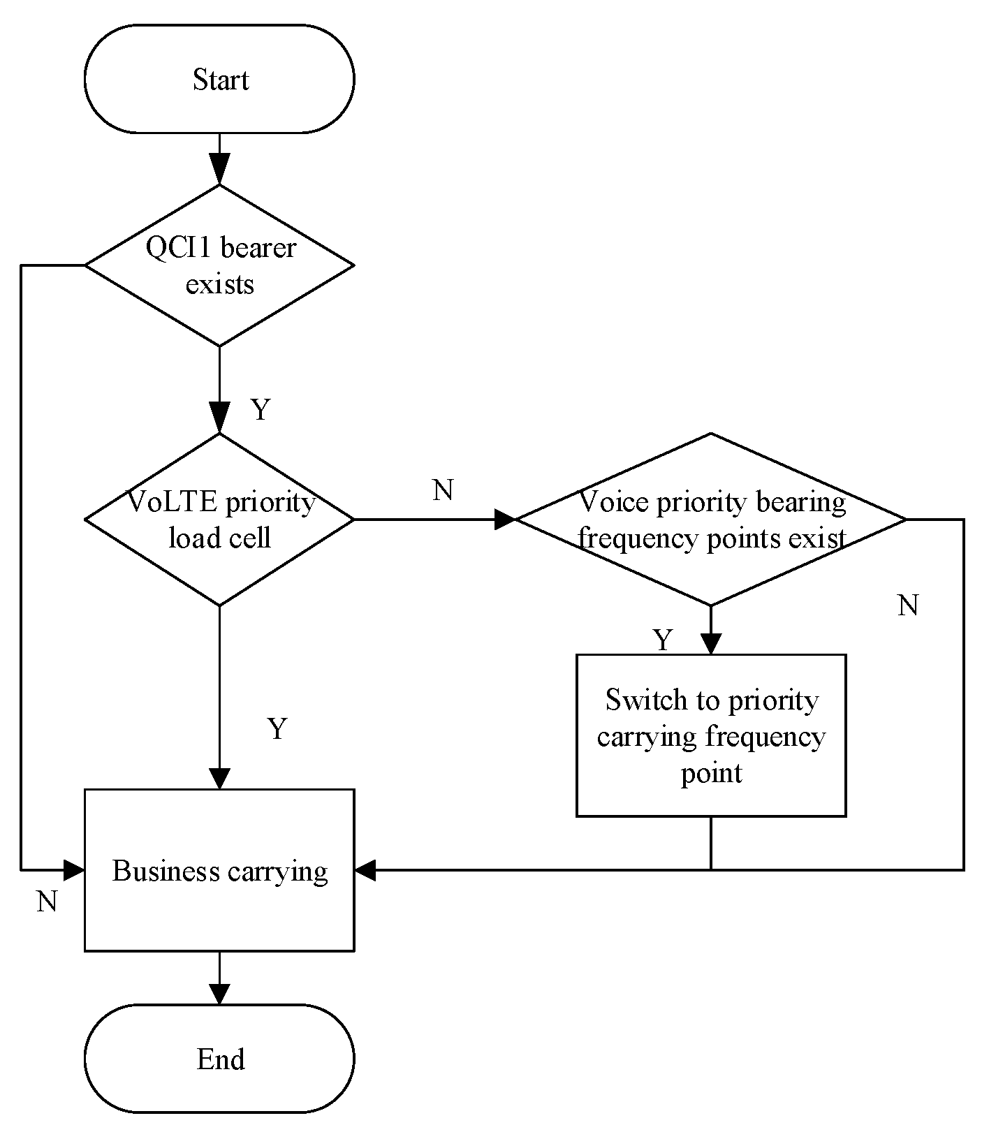
The second type is that VoLTE is carried on the home 4G cell, and when VoLTE service is established, a service-based handover to the respective home 4G network is established. The focus of this solution is how the 5G UE can realize the VoLTE service bearing on the home 4G network. This solution requires the shared anchor eNodeB of the contractor to support the PLMN-based configuration of the neighbor list and frequency priority setting based on PLMN. The VoLTE must be configured based on the service priority policy to be carried on the specific 4G carrier first. In the shared area, the 5G UE resides on the 4G anchor point of the contractor. When the 4G anchor point of the contractor receives the request for VoLTE initiated by the 5G UE, i.e., setup request of quality of service (QoS) class identifier (QCI) 1, the 4G anchor point of the contractor triggers the service-based inter-frequency handover so that the 5G UE returns to the specified 4G for VoLTE service. In this way, each shared operator has an LTE carrier specifically bearing the VoLTE feature. However, the sharing VoLTE user makes an additional inter-frequency handover at the initiation service stage, which increases the VoLTE access delay. The handover flow is shown in
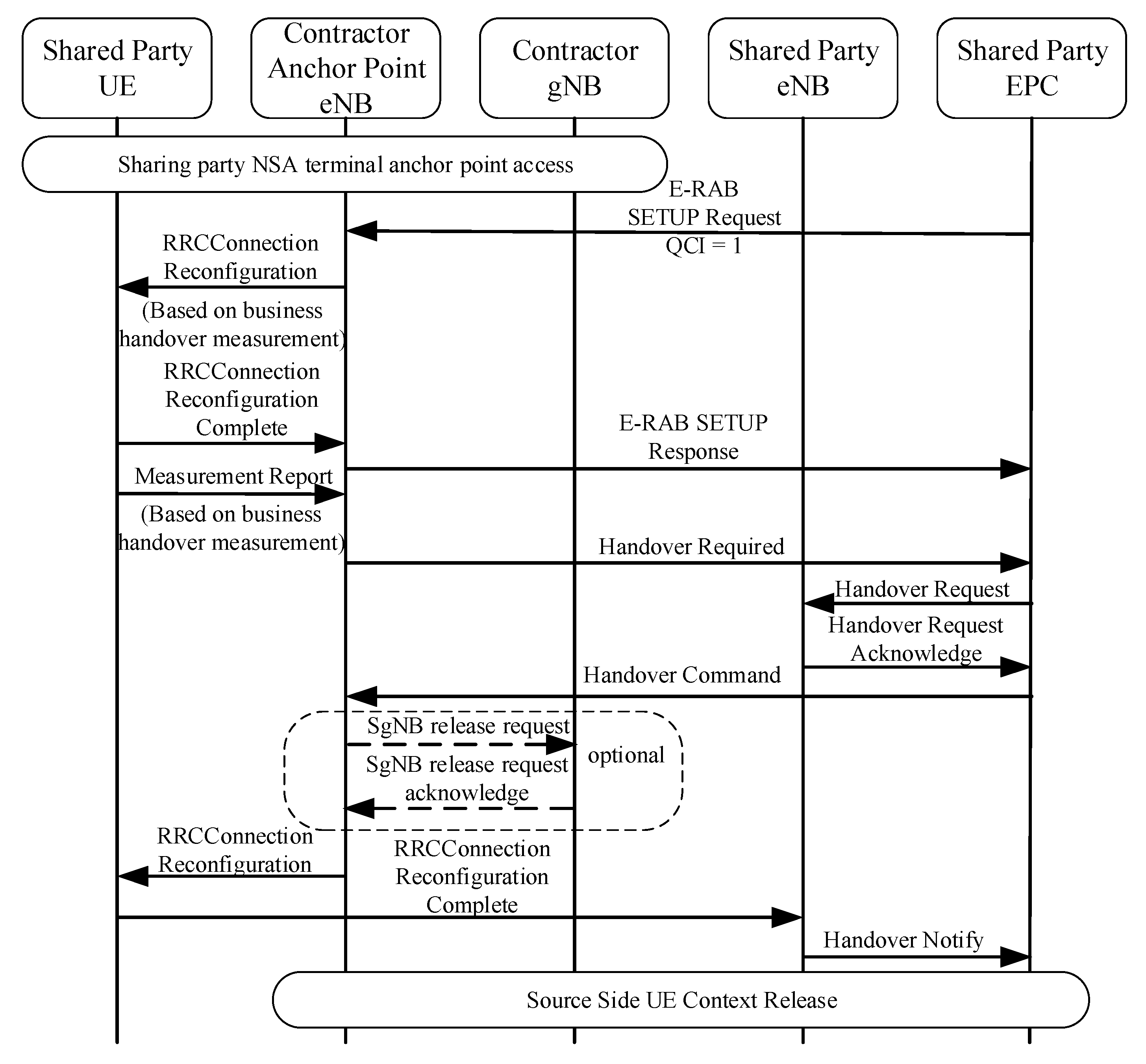
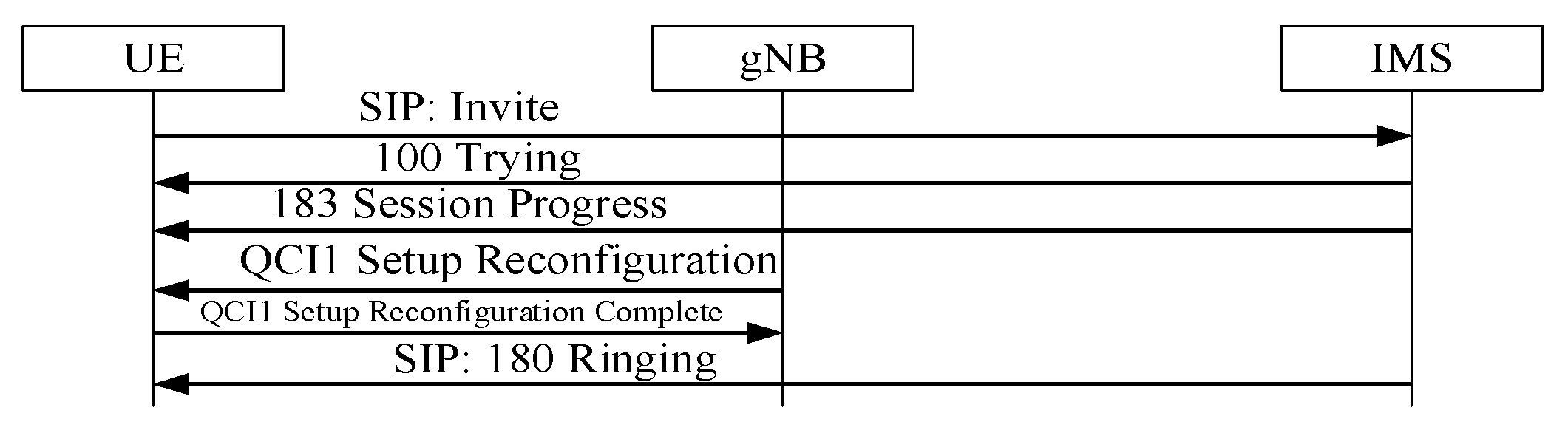
Figure 4.
As can be seen in
Figure 4, in the handover process, the sharer EPC first initiates an evolved radio access bearer (E-RAB) setting a request message to the contractor anchor eNodeB. The contractor anchor eNodeB initiates an RRC connection configuration instruction to the sharer UE based on the service handover measurement. After receiving the configuration completion feedback, the contractor anchor eNodeB sends an E-RAB setting response to the sharer EPC to complete the E-RAB setting process. After receiving the measurement report of the sharer UE, the contractor anchor eNodeB sends a handover request to the sharer EPC. Interaction is performed between the sharer EPC and the sharer eNodeB to complete the handover request confirmation. The sharer EPC sends a handover command to the contractor anchor eNodeB. Afterward, the SgNodeB release can be performed between the anchor eNodeB and gNodeB of the contractor, and this step is optional in voice service. After the contractor anchor eNodeB sends the RRC connection configuration to the sharer UE, the UE feeds back a completion indication of the RRC connection configuration to the sharer eNodeB. Finally, the sharer eNodeB sends a handover notification to the sharer EPC to complete the handover process.
The symbols used to evaluate the communication costs are listed in
Table 1. For each handover protocol, all the communication costs of the handover phases are summed to represent the communication cost for that protocol. These symbols are used to represent the cost of communication between different entities.
For the communication cost shown in
Figure 4, in addition to the regular VoLTE delay, such as the sharer NSA UE anchor access delay and the source-side UE release context delay, the additional handover adds four times of communication between the sharer UE and the contractor eNodeB, one time of communication between the sharer UE and eNodeB, four times of communication between the contractor eNodeB and the sharer EPC, and three times of communication between the sharer eNodeB and the sharer EPC. In addition, SgNodeB is released as a non-essential process. The whole communication cost can be written as:
is the sharer NSA UE anchor access delay; is the source-side UE release context delay; is the SgNodeB release delay, including two times of communication between the contractor anchor eNodeB and the contractor gNodeB if it is configured to require release.
4.2. SA Sharing EPS Fallback Process
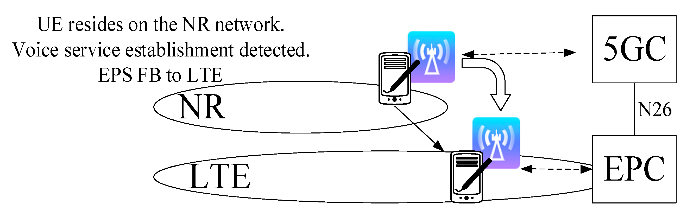
At the early stage of SA sharing network deployment, VoNR is not mature, and EPS fallback is needed as a temporary transition solution to fallback the voice service to the LTE network, as shown in
Figure 5. gNodeB needs to enable the base station sharing function and configure both eNodeBs as neighbors [
36].
EPS fallback can be implemented based on either handover or redirection. The process is shown in
Figure 6.
4.2.1. EPS Fallback Based on Handover
As can be seen in
Figure 6A, the UE sends a SIP INVITE message to the 5GC requesting the voice session setup after the 5G entry registration process. After the gNodeB receives the PDU SESSION RESOURCE MODIFY REQUEST message, it directs the gNodeB to establish a voice-dedicated bearer for 5QI1. Afterward, the gNodeB sends the inter-system B1 event measurement and receives the measurement report. gNodeB replies to the 5GC rejecting the setup of PDU Session 5QI1 and directs ims-voice-eps-fallback-or-fallback-triggered. gNodeB determines based on the handover parameter configuration and UE capability. The EPC establishes a handover request to the eNodeB and, after receiving the response, sends a successful handover request response message from the eNodeB to the 5GC. 5GC establishes a handover command to the gNodeB. gNodeB sends a handover command to the UE. Finally, the handover-based EPS fallback is completed. The terminal access unit (TAU) process and the process of setup VoLTE will be specifically analyzed in the subsequent sections on the call setup delay.
The communication cost of handover-based EPS fallback is shown in Equation (4).
As can be seen in
Figure 6A, there are fifteen times of communication between UE and gNodeB, seven times of communication between gNodeB and 5GC; two times of communication between 5GC and EPC, and between EPC and eNodeB, the communication between the remaining entities is only one time.
4.2.2. EPS Fallback Based on Redirection
As can be seen in
Figure 6B, after the 5G registration process, the pre-process is the same as the handover-based EPS fallback. After the gNodeB responds to the 5GC that the UE context setup is done, it will send a blind A2 event measurement control to the UE. Then, the UE responds that the RRC connection reconfiguration is completed. For the blind A2 event, gNodeB sends RRC release with target frequency and other information to UE, which performs random access to the target LTE cell based on the target frequency and other information. UE receives the random access response from the target LTE cell. At this point, the redirection-based EPS fallback process is completed.
Equation (5) is the calculation method of voice access delay under redirection.
is the redirection judgment delay. There are thirteen communications between UE and gNodeB, two communications between UE and eNodeB, andthree times of communications between gNodeB and 5GC. The meanings of the remaining parameters in Equation (5) are the same as those investigated in
Table 1.
Subsequently, EPS Fallback voice service is taken over by VoLTE; 5G only conducts data service and only conducts interoperability with 4G to ensure voice service continuity. It should be noted that EPS fallback allows 5G UE to reside in 5G NR but does not provide voice service. Due to the delay in the fallback process, the call setup time increases.
4.3. SA Sharing VoNR Process
VoNR refers to voice services carried end-to-end by NR, 5GC, and IMS [
37,
38]. When the VoNR feature is mature, only the gNodeB is shared. NR accesses 5GC to provide the voice service through VoNR. VoNR services are bearing in the 5G network, which can realize the unification of data and voice services in the same network. Compared with EPS fallback, the advantages of VoNR are apparent: firstly, there is no need to fall back, so the call setup delay is shorter; secondly, it supports 5G voice and data services concurrently, as shown in
Figure 7.
The VoNR handover process involves interoperation between 5G and 4G. 5GC and EPC complete the handover and contextual information interoperation through the N26 interface during the handover process to ensure the continuity of the session. The flow of VoNR is shown in
Figure 8.
In the past network era, networks in high-frequency bands have had a coverage discontinuity problem [
25], especially in mobile scenarios, where most users have a short residency time in the band, and 5G is no exception. Due to the discontinuous network coverage caused by the high-frequency band of 5G, by the edge of 5G, VoNR will switch to the respective 4G via N26 when it is unable to provide voice services, similar to the SRVCC scheme in the 4G era [
39]. The residency time in this region can be modeled by a hyper-exponentially distributed random variable. As shown in Equation (6),
is the average rate, and
is the mobility variability parameter.
The VoNR solution also supports smooth handover between VoNR and VoLTE through the Inter-RAT handover mechanism [
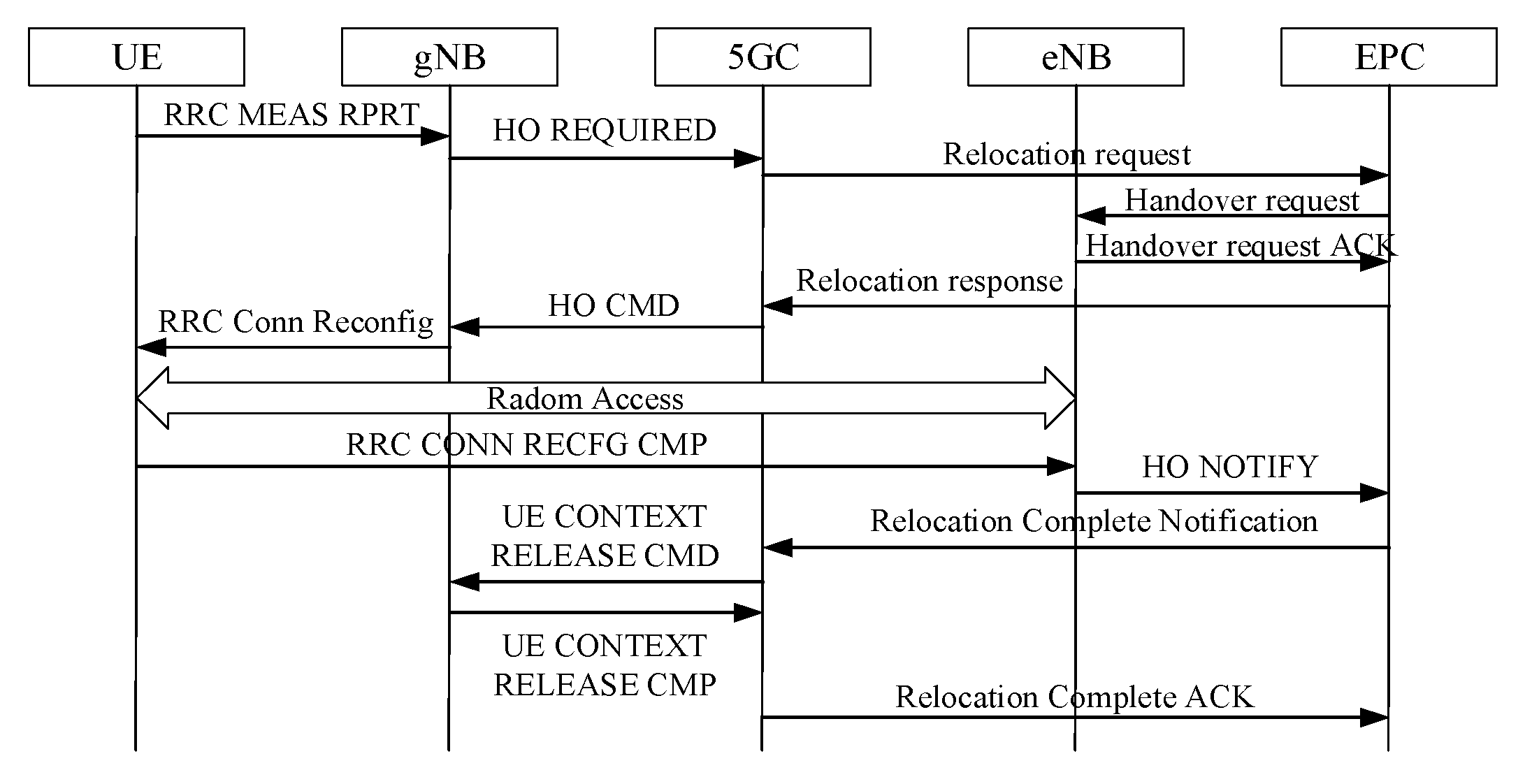
38]. Its handover flow is shown in
Figure 9.
The whole handover process can be divided into six steps: firstly, the UE needs to send the measurement report to the gNodeB; secondly, the gNodeB executes the handover judgment and then initiates the handover request to the 5GC; thirdly, the target eNodeB prepares for the handover and then sends the handover indication; fourthly, the UE initiates random access at the target eNodeB; fifthly, the UE switches to the target cell; finally, the source gNodeB is notified of the handover completion, and the UE context is released.
Equation (7) is the calculation method of handover delay from VoNR to VoLTE.
is the time delay of the UE to initiate random access in eNodeB. The rest of the parameters are investigated in the same way as in
Table 1.
As can be seen in
Figure 9, there are two times of communication between UE and gNodeB; one time of communication between UE and eNodeB; four times of communication between gNodeB and 5GC; four times of communication between 5GC and EPC; and three times of communication between EPC and eNodeB.
Based on theoretical analysis, the access delay of VoLTE’s non-back-to-home solution is shorter than the back-to-home solution in the NSA sharing phase, about 2.0 s, which is more recommended. The setup delay of EPS fallback based on handover or redirection is about 3.0~4.0 s in SA–SA calls, which increases compared with VoLTE setup delay. Because of the large time delay introduced, EPS fallback can only be used as a transition solution in the early SA sharing deployment. The theoretical VoNR setup delay is about 1.5~2.0 s, which is the lowest and the ideal solution.
5. Performance Analysis
5.1. Testing Environment
The data were processed from field measurements with a large sample size (i.e., 50 VoLTE/EPS-fallback/VoNR calls for each scenario). The performance testing was conducted in the same-area LTE/NR commercial networks. The test area has residential buildings, industrial parks, small commercial streets, and schools, which is a typical general urban test scenario. The network architecture is shown in
Figure 1. Network uplink and downlink configuration: 30% loading.
In the NSA sharing VoLTE feature test, two carriers were configured at operator A as anchor point carriers for operator A and operator B, respectively, broadcasting their respective PLMNs, which were used independently by operator A and operator B. The shared area was configured by the contractor, and the shared NR base station was closed.
We next verified whether users of different operators could fall back to their respective 4G networks when EPS fallback was adopted as a handover/redirection strategy. In this case, the 5G cells were configured as sharing carriers, and the 4G cells of operators A and B were set up with each other in a neighboring relationship. The 4G cell was configured to cover the same area as the 5G SA cell.
In the VoNR test, the NR cell supported the VoNR feature, and the LTE cell supported the VoLTE feature. NR cells and LTE cells were working properly and configured with neighbors.
The carrier configuration is shown in
Table 2.
During the test, for the SIM cards of both sides, data services were contracted by the default bearer QCI9 and kept the priority of SIM cards in each test area consistent. QCI1 was used by both the contractor and the sharer of the voice-dedicated load.
The results were derived from the UE side through post-processing scripts of the collected logs.
5.2. NSA Sharing VoLTE Performance Analysis
We conducted access tests for different types of UEs under the two solutions in
Section 4.1 separately. The test results are as follows.
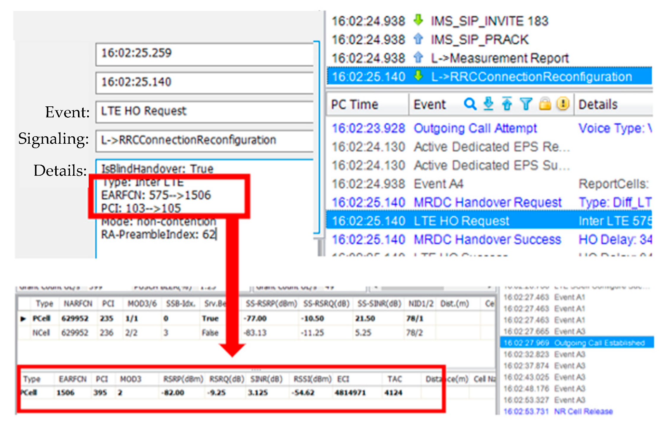
In the sharer 5G UE–sharer 5G UE call scenario, sharer 5G UE resided on the sharer anchor frequency point 575, PCI 103, and initiated VoLTE request. After establishing bearer with QCI of 1, triggers switched to the VoLTE-dedicated frequency point 1506. VoLTE was successfully established, as shown in
Figure 10.
In the contractor 5G UE–contractor 5G UE call scenario, like the sharer 5G UE–sharer 5G UE call scenario, the contractor UE switched from anchor frequency 100 to VoLTE-dedicated frequency 1825.
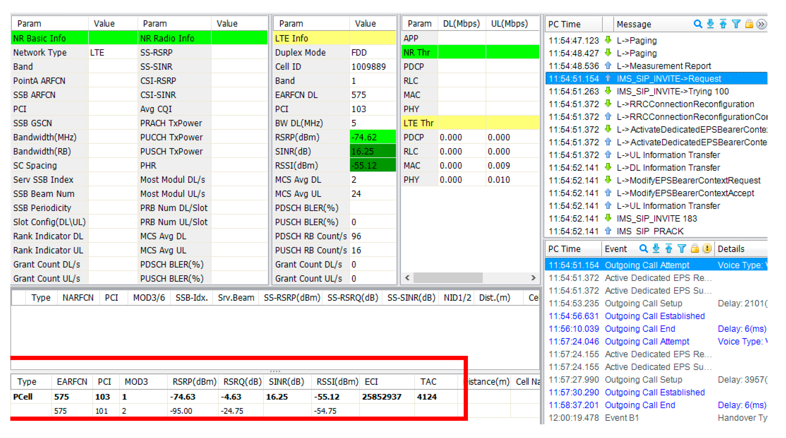
In the sharer 5G UE–sharer 5G UE call scenario, the sharer 5G UE resided on anchor frequency 575 to initiate VoLTE and established the QCI1 bearer. VoLTE setup to release was completed at anchor frequency 575, as shown in
Figure 11.
In the contractor–contractor 5G UE call scenario, from service setup to release, it was also always done at the anchor 100 frequency point.
It can be seen that the actual process is consistent with
Section 4.1. This shows that both solutions are technically achievable. VoLTE bearing in the contractor 4G shared anchor cell solution has the advantage of eliminating the time delay caused by handover.
Since there is one more handover process in the VoLTE setup process in the return to the home frequency point scheme, we conducted experiments on this. We compared the average call setup delay of the sharer NSA UE returning the specified frequency point and not returning the specified frequency point, and the results are shown in
Figure 12.
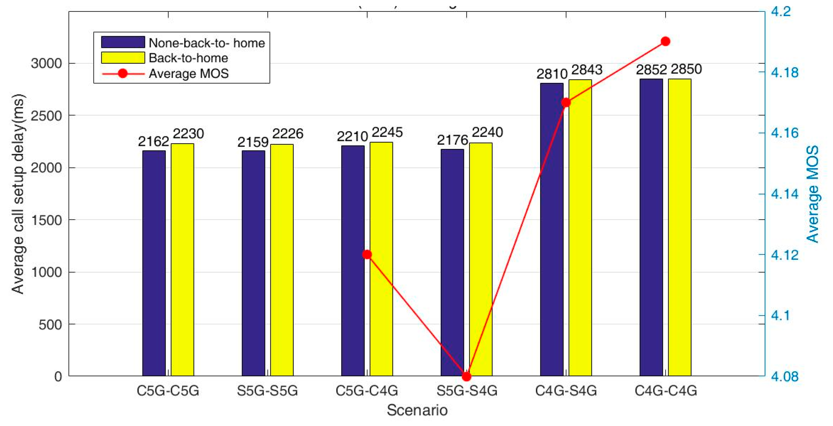
In
Figure 12, C5G/C4G means contractor 5G/4G, and S5G/S4G means shared 5G/4G. It can be seen that various combinations of VoLTE call setup delay are within 2.9 s. The delay of the back-to-home solution 5G–5G call as sharer is around 2228 ms, and the delay of the non-back-to-home solution is around 2161 ms regardless of operator A or B. The overall VoLTE setup delay of back to home is about 68 ms longer than not returning.
Figure 13 shows that the single-end handover brings 35 ms, and both NSA UEs need 70 ms for handover, which is the same as the actual delay difference.
The VoLTE call setup delay for 5G NSA UE to 4G LTE UE is around 2.2 s. The VoLTE call setup delay for 4G LTE UE to 4G LTE UE is around 2.8 s. 5G to 4G delay is better than 4G to 4G, as the wireless side does not bring too much delay due to the different wireless node networking.
The VoLTE call setup delay of the contractor 5G NSA UE to the contractor 4G LTE UE back-to-home solution is better than that of the non-back-to-home solution, with an average difference of 35 ms. This is because the 5G NSA UE of the contractor in the back-to-home network scenario needs to experience one additional handover.
Similarly, for the VoLTE call setup delay of 5G NSA UE on the sharer to 4G LTE UE on the sharer, the average value of the two solutions differs by 64 ms, which is because 4/5G UE in the back-to-home network solution needs to experience two additional handovers (both UEs need to handover to the dedicated frequency). When the contractor 4G LTE UE calls the sharer 4G LTE UE, the difference in delay between the two solutions is 33 ms, which is due to one additional handover of the sharer 4G LTE UE. The 4G LTE UE to the 4G LTE UE, both from the contractor, has almost no difference in delay, as no handover is required for either solution.
The setup delay of sharer networks is, overall, about 4 ms shorter than the contractor, which is mainly suspected to be caused by the geographical proximity of the core network and thus can be ignored. The mean opinion score (MOS) of VoLTE service under each UE is normal, and the average value of NSA UE MOS is about 4.10; the average 4G MOS is about 4.17.
The following conclusion can be drawn: in the 5G NSA sharing stage, VoLTE is not much improved compared with 4G, all around 2.2~2.8 s. The contractor and the sharer have the same delay, and sharing brings no additional difference in experience. The back-to-home solution is slightly worse than the non-back-to-home solution in terms of delay, which is brought about by the additional handover, with the handover delay of a single-end UE being around 35 ms. In summary, in the 5G NSA sharing VoLTE service scenario, the non-back-to-home solution can reduce the call setup delay. Therefore, from the time delay perspective, it is recommended to use the non-back-to-home voice solution.
5.3. SA Sharing EPS Fallback Performance Analysis
We conducted EPS fallback call setup tests based on handover and redirection in
Section 4.2 separately. The test results are as follows.
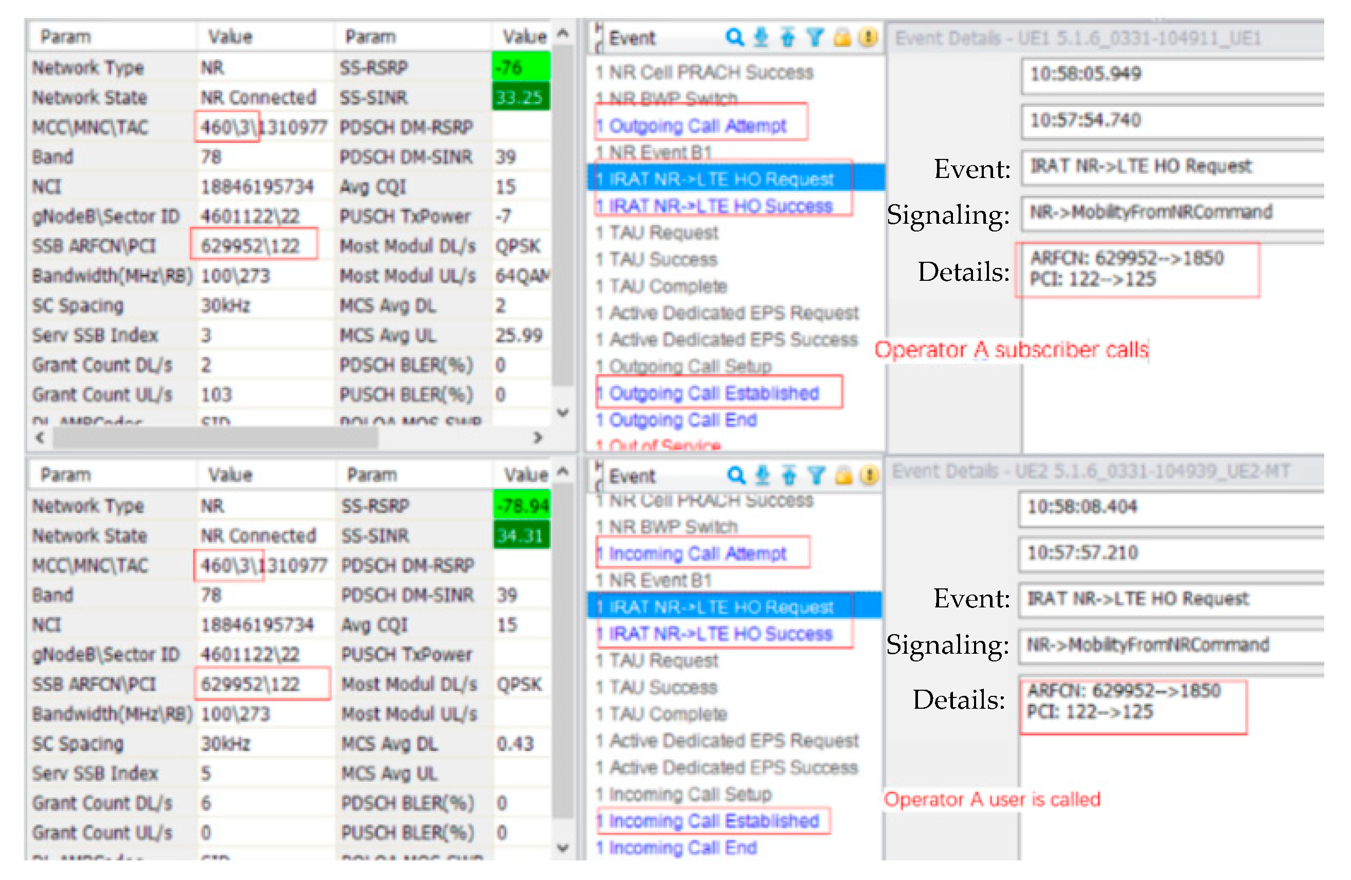
UE1 initiates a voice service request to UE2, which can be seen in the IRAT NR→LTE HO request message ARFCN: 629952(5G) to 1850(4G), PCI:122(5G) to 125(4G), after which IRAT NR→LTE HO success and outgoing call are received. For the operator A user, based on the handover back to the LTE network of operator A, voice service is established successfully, and the call is normal. The UE supports the normal fallback of voice services based on different PLMNs to their respective 4G networks through PSHO. The signaling flow is shown in
Figure 14.
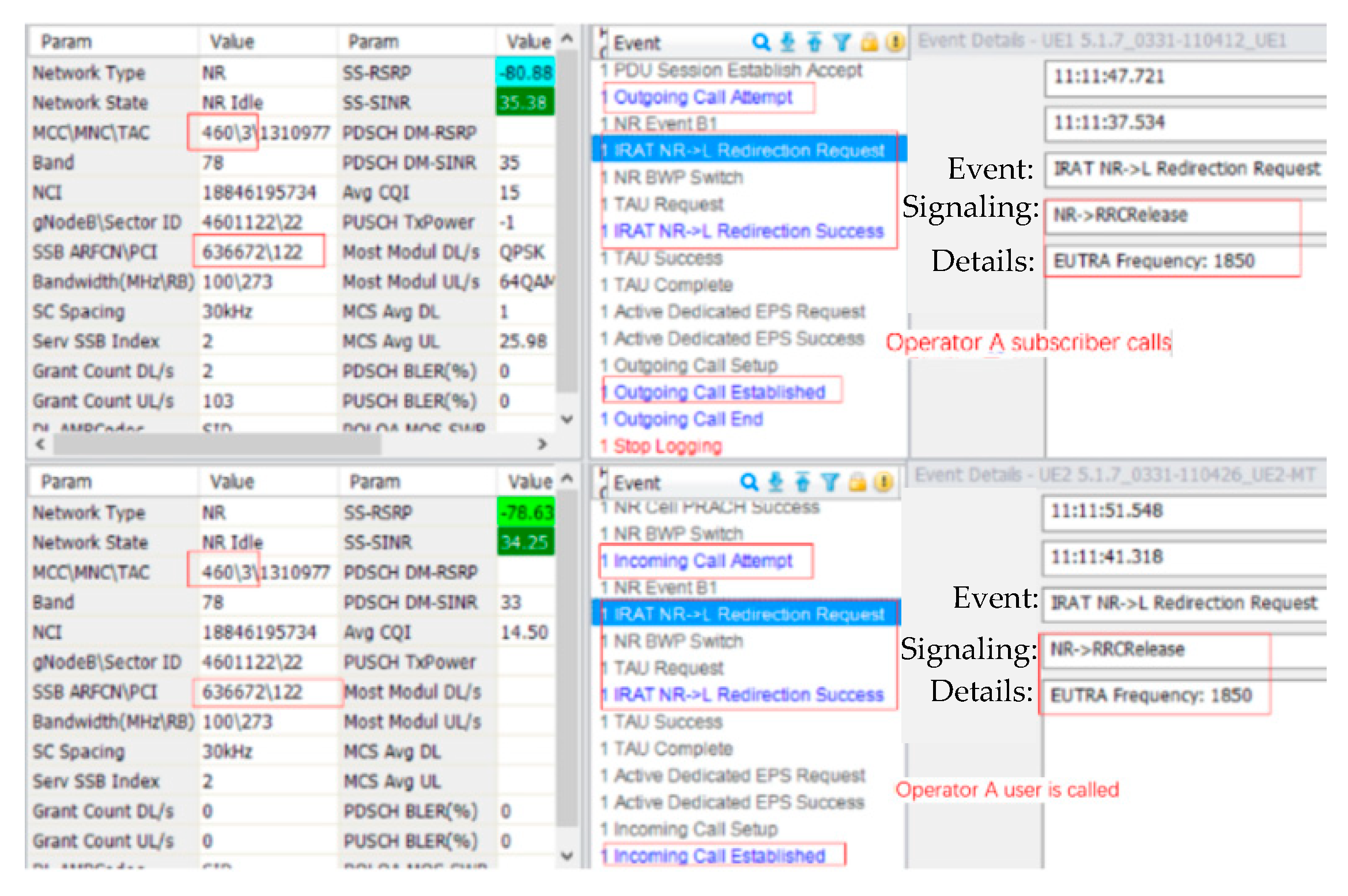
UE1 initiates a voice service request to UE2, which can be seen in the IRAT NR→ L redirection request message EUREA frequency: 1850 (carrier A 4G), after which IRAT NR→ L redirection success and outgoing call are received. In the established message, it can be seen that the user of operator A can fall back to the LTE network of operator A based on redirection under the 5G network of operator B. The voice service is established successfully, and the call is normal. The signaling flow is shown in
Figure 15.
Voice services are established on the SA sharing 5G network, and UE can fall back to the 4G network by handover/redirection. Both options are achievable.
Due to the different handover and redirection processes, experiments were conducted to compare the call setup delay, and the results are shown in
Table 3.
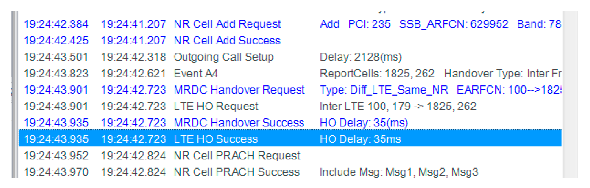
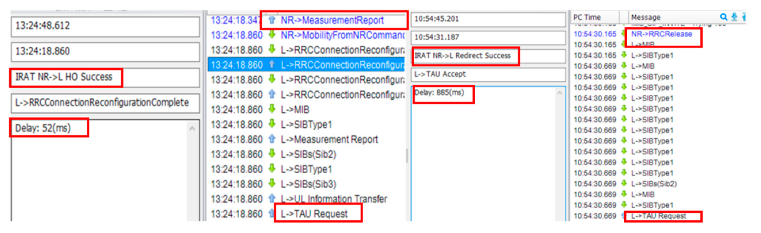
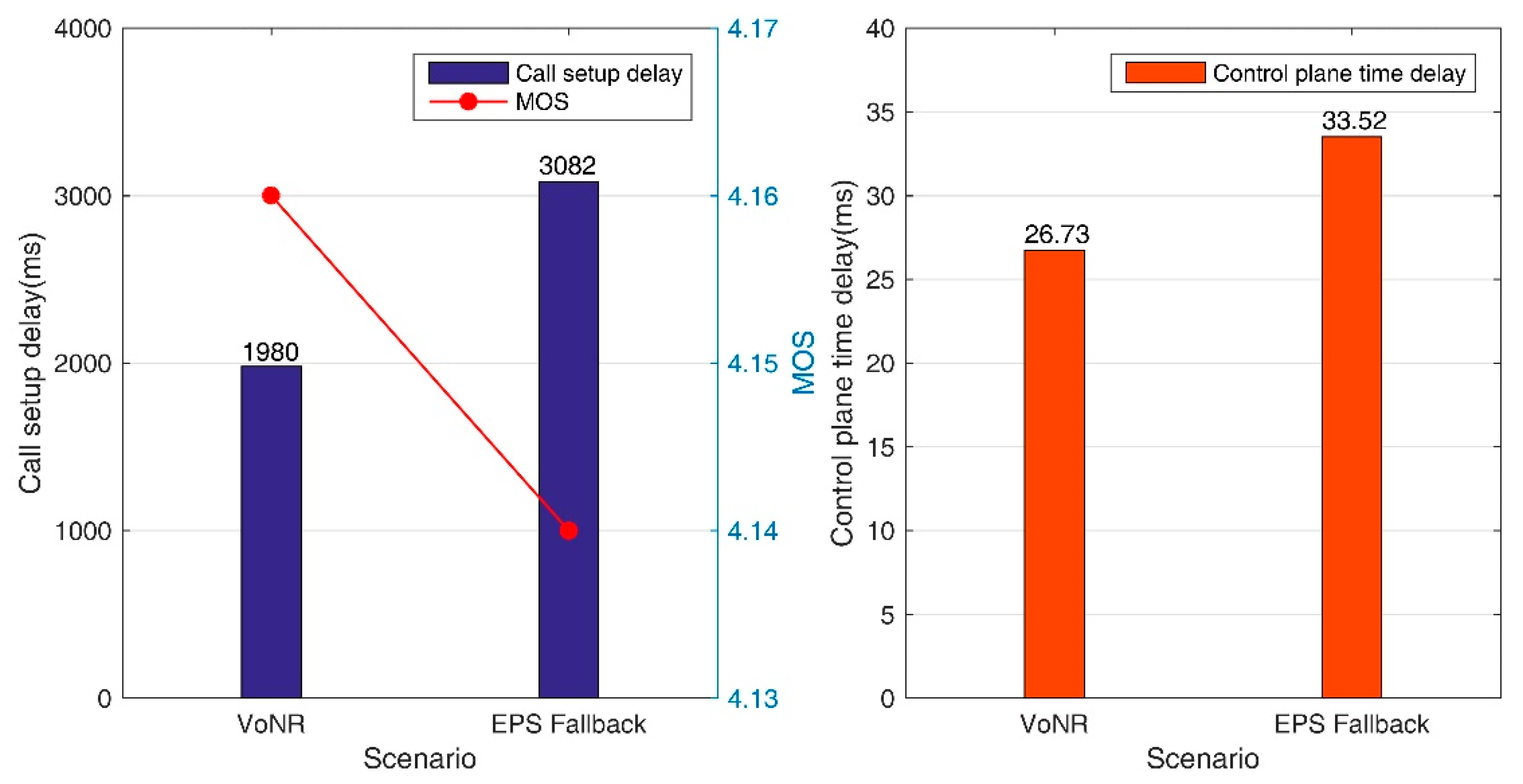
The setup delay based on handover is 3082 ms and on redirection is 3911 ms. Handover-based EPS fallback call setup delay is shorter than redirection: about 830 ms. The difference in call setup delay between the two is mainly reflected in the delay difference between the handover and redirection process. The delay of the handover process is 52 ms, and the delay of the redirection process is 885 ms, as shown in
Figure 16.
As can be seen in the
Figure 6 comparison, there is an RRC release process for redirection. The handover process is that the RRC is always in the connected state, and the redirection is that when the RRC is in the connected state, it needs to be released first and then reconnected on another frequency through the redirected frequency and initiates random access again. This is also the main reason why the delay of the redirection process is longer than that of the handover.
In contrast, the handover-based EPS fallback scheme can save the process of returning to the idle state and then access, which can greatly shorten call setup delay and can improve voice service experience in the early stage of 5G SA network construction.
The average call setup delay for the handover-based EPS fallback is longer than the NSA delay investigated in
Section 4.2: about 850 ms. The 4G network fallback is more complicated than the handover process when setup voice service by VoLTE, thus increasing the voice setup call duration. At the same time, data traffic will also be transmitted over LTE, which will significantly reduce the data rate and affect the user experience.
This shows that EPS fallback can only play a transitional role in terms of voice continuity assurance in the early stages of 5G SA deployment based on 5GC. However, the high setup delay and reducing data rate will affect the user experience to a certain extent.
5.4. SA Sharing VoNR Performance Analysis
5.4.1. Comparison of VoNR and EPS Fallback
The call setup delay of EPS Fallback–EPS Fallback call is about 1102 ms longer than that of the VoNR–VoNR call. The control plane delays are also generally longer compared to the VoNR–VoNR call. As can be seen from the setup flow in
Figure 8, the VoNR voice setup process has no handover or redirection process compared to EPS fallback. After SIP invite, it enters the process of QCI1 bearer information distribution, and upon completion, it initiates SIP 180 ringing. Compared to EPS fallback, it eliminates TAU and other related delays. Therefore, the VoNR setup delay will be much shorter than that of EPS fallback.
At the same time, the MOS of VoNR is better than EPS fallback. Therefore, from the perspective of time delay or user experience, VoNR is the more recommended voice solution.
5.4.2. Handover from VoNR to VoLTE
Experiments were performed on Inter-RAT-based VoNR to VoLTE handover according to
Section 4.3 5G network coverage discontinuity scenario. The test results are shown in
Table 4.
The average setup delay is 1032 ms, which is much shorter than the EPS fallback setup delay. VoNR to VoLTE can achieve smooth handover. For the 5G-to-4G handover delay, the control plane delays are better than EPS fallback.
According to
Figure 6 and
Figure 8 and Equations (4), (5) and (7), it can be seen that during the handover process from VoNR to VoLTE, there is less interoperation between the UE and the gNodeB. In Equation (7), the coefficient of δ is 2, indicating that the UE has only two communications with the gNodeB in the whole process. In the process of EPS fallback, whether it is based on handover or redirection, it can be seen from Equations (4) and (5) that the coefficient of δ is over 10, indicating that the UE communicates with the gNodeB over 10 times in the whole process. Therefore, theoretically, the handover delay from VoNR to VoLTE should be shorter than the handover or redirection delay of EPS fallback. The test results in this chapter also fully confirm the results of the theoretical analysis in
Section 4.
Based on the field network verifications, the following conclusions can be drawn: In the 5G NSA sharing VoLTE service scenario, the non-back-to-home voice solution is consistent with the theoretical analysis and has a smaller call setup delay of about 2.2 s. The handover-based EPS fallback has a shorter call setup delay of about 0.8 s compared with the redirection, but since the fallback is more complex than the handover process in VoLTE, the call setup delay is 0.9 s higher than the VoLTE solution. VoNR has the best network setup delay of about 2.0 s according to field experiments. Therefore, voice service needs to evolve to VoNR as soon as possible to bring a better network experience to users.
6. Conclusions
In this paper, all the results presented are based on commercially available NSA/SA shared networks. Firstly, we investigated the basic architecture of 5G sharing. Subsequently, an achievable theoretical solution of the voice service under different evolutionary stages was conducted: VoLTE at the NSA sharing stage, EPS fallback at the early stage of SA sharing, and VoNR at the SA sharing maturity stage. After theoretical analysis, the NSA sharing VoLTE setup delay is about 2.0~3.0 s, the EPS fallback setup delay based on handover or redirection is about 3.0~4.0 s, and SA sharing VoNR setup delay is about 1.5~2.0 s.
Realistic testing environments of this study were built based on widespread equipment suppliers in the first live commercial 5G sharing networks. We thus conducted field tests on each solution. The performance of VoLTE in both back-to-home and non-back-to-home construction solution was verified in the NSA sharing VoLTE stage. Both are technically achievable. It is found that the VoLTE at NSA is not much improved compared with 4G, all around 2.2~2.8 s, which is consistent with the theoretical analysis value. There is almost no difference in delay between the contractor and the sharer, and sharing brings no additional difference in experience. The back-to-home solution is slightly worse than the non-back-to-home solution in terms of delay, which is brought about by the additional handover, with the handover delay of a single-end UE being around 35 ms.
In EPS fallback test, it was first verified that EPS fallback can be achieved based on either handover or redirection. Therefore, in the initial stage of SA network construction, EPS fallback is a practical voice solution. The average setup delay is about 3.1 s for handover-based EPS fallback and about 3.9 s for the redirection-based version. This is consistent with the theoretical analysis. The average setup delay based on redirection is relatively high. Thus, from the perspective of delay, it is more highly recommended to deploy handover-based EPS fallback.
In the SA sharing VoNR test, the average VoNR setup delay was obtained at about 1.9 s. Compared with EPS fallback, it was reduced by about 1.1 s, the VoNR control plane delay was shorter, and the MOS value was higher, which verifies the superiority of VoNR. Meanwhile, at the 4/5G border, it was verified that VoNR can switch to VoLTE to ensure the continuity of voice service and saved 33 ms compared to EPS fallback.
In summary, the paper provides a variety of solutions to improve voice services in different evolutionary stages of 5G sharing networks. From the theoretical and practical analysis, it can be verified that EPS fallback can only be deployed as a transition solution. VoNR as the ultimate voice solution can bring the lowest access delay, further simplify the implementation process, and improve the best voice quality. Operators worldwide can deploy as needed based on the current network.
Due to factors such as network load and lack of users, the research is not comprehensive enough. This is where the follow-up improvement of this paper is needed. The subsequent work of the paper includes research on how to further improve VoNR quality and call performance, a detailed evaluation of call jitter, packet loss error rate, etc.


