Abstract
This article presents a modified active-disturbance-rejection control (ADRC) combined with a sliding mode control (SMC) regarding the tracking control problems for plants with unmatched uncertainty. The proposed modified active-disturbance-rejection control with sliding mode (ADRC-SM) employs a reduced-order extended state observer (ESO) for estimating various uncertainties of system in time, including unmatched and matched uncertainties. Meanwhile, a novel reaching law of SMC was designed by using the cycloid function as the main controller of ADRC, which ensures the robustness of the uncertain system. Due to the reduced-order ESO tracking and compensating for various uncertainties in the system as a total disturbance, the upper bound of the disturbance in the SMC is relaxed. The gain coefficient of the reaching law only needs to be designed to be larger than the limit of the lumped disturbance; thus, the chattering problem is greatly reduced. The designed new reaching law of the cycloid function shortens the time for the system state’s convergence to the sliding mode’s surface. The cycloid function replaces the switching function in the traditional reaching law, making the actual control input continuous and shortening the approach time. Compared with traditional ADRC-SM, the use of multiple ESOs or intelligent algorithms to approximate plant parameters can be avoided, the design is simplified, its robustness is enhanced, computational costs are reduced, and the convergence time is reduced. The controlled object with unmatched uncertainty is transformed into a system with matched uncertainty using state-space transformation, which reduces the complexity of the controller’s design. In addition, the stability analysis of the closed-loop system is carried out based on the Lyapunov method. Simulations and experiments verify that the modified ADRC-SM has the merits of fast response, small overshoot, small steady-state error, strong anti-interference competence, and high control accuracy.
1. Introduction
Uncertainty in real control systems refers to unmodeled dynamics, parameter changes, disturbances, etc. [1]. The existence of these uncertainties will destroy the control performance of the system, and it is difficult to undertake the stable motion of the system [2]. According to the location of uncertainty in the control system, it can be roughly divided into two groups: matched and unmatched uncertainty. Matching uncertainty generally refers to the presence of disturbance and control inputs in the same channel, and non-matching uncertainty refers to their occurrence in different channels [3]. The uncertainty present in many practical systems may not satisfy the common matched condition [4,5], such as flexible articulated manipulators [6], active vehicle suspensions, etc. Due to the existence of flexible structures, it is difficult to control such systems with unmatched uncertainty [7]. In the magnetic levitation system, the perturbation of the track input and the control input act on different channels [8]. For PMSM, the disturbance caused by parameter uncertainty and the disturbance caused by load torque changes enter the system through different channels of control inputs [9]. Another typical example is a flight system in which the concentrated disturbance torque does not pass through the input channel but directly affects the state, which is caused by unmodeled dynamics, parameter changes and external wind [10].
In order to effectively control the unmatched dynamic uncertainty in the system and to improve control accuracies, researchers have proposed a very diverse control strategies from different perspectives. For example, the most widely used PID control is robust to the uncertainty of the plant, but it is weak in coping with time-varying perturbations [11]. The adaptive control can be adjusted online according to the previous state of the system, and it iteratively updates to obtain an optimal solution for the system [12]. However, in the iterations of parameter estimation, the results of the transient response can lead to large errors [13]. Robust control can overcome model uncertainty, but it can only cope with a limited range of uncertainty [14]. Intelligent control algorithms such as fuzzy neural network can solve the unknown uncertainty problem of the system by applying a large amount of pre-training. However, its function approximator has a large amount of computation, slow convergence, and it is hard to ensure the stability of the system when the system’s state changes suddenly [15].
In the process of traditional SMC dealing with such systems, the sliding motion is susceptible to mismatch uncertainty [16]. A simple and effective solution is to add an integral action to the control law to counteract the steady-state error [17]. Of course, the integral action will also induce bad performance such as overshoots and long approach times, reducing nominal control performances [18]. Another straightforward solution is to obtain new control laws. A novel SMC method based on a disturbance observer (DOB) was developed in [19] to counteract mismatched perturbations, constructing a novel sliding mode surface incorporating perturbation estimations. Numerical experiments demonstrate that the proposed novel SMC is robust to mismatched uncertainty and has improved control performances than traditional SMCs and integral SMCs. The chatter problem in these methods is still a serious problem that needs to be solved. In the disturbance observer-based control method, an efficient disturbance observer is first needed to estimate time-varying uncertainties [20]. ADRC is a approach proposed by Prof. Han [21] for attributing various uncertainties in the system to total disturbances. Professor Gao [22] further proposed the corresponding linear control method. The characteristic of this method is that the controller does not completely depend on the plant and has strong adaptability. It is one of the better solutions to the uncertainty problem of the plant in practical engineering applications. The literature [23] proposed an SM-ADRC. The sliding mode is mainly used to deal with the disturbance estimation error of ESO to improve the sensitivity and anti-disturbance competence of the controller relative to terminal load changes. However, there is an error when ESO estimates disturbances, and the robustness and anti-disturbance of ADRC are limited by using the ESO estimate as the feedback control law. Moreover, the switching term in the traditional sliding-mode reaching law has a certain ability to suppress unknown modeling and external disturbances while also exciting high-frequency dynamics. Therefore, the key to SMC is to accurately compensate for disturbances and to decrease arrival times [24,25]. The improvement of the reaching law is a valid and simple method for reducing the reaching time [26], which can directly improve the dynamic performance of the SMC in the arrival stage, and at the same time, it can reduce the flutter [27].
Aiming at the above problems, this paper designs an improved ADRC-SM based on a novel reaching law, which converts the state variables of the original system into errors and predicts the uncertainty and environmental disturbances of the system. Combined with the ESO, the multi-channel nonlinear uncertainty in the system is observed and compensated, which effectively reduces the chattering phenomenon of the control output and improves the robustness of the controller. Then, a new brachistochrone reaching law (BRL) is designed so that the initial state can quickly reach the designed sliding surface (SF). We solve the problem in which the nonlinear system cannot guarantee control accuracies due to the existence of non-matching uncertainty; we enhance the anti-interference ability of the system, and then we shorten the approximation time. The method of combining reduced-order ESO with the SMC proposed in this study is different from the controller structure applied in power converters proposed by [28]. The contributions of this study can be summarized in three points: (i) Distinct from the existing reaching law, the brachistochrone reaching law introduces the cycloid function into the reaching law for the first time. It is a novel reaching law with a simple structure. (ii) Compared with the traditional reaching law and exponential reaching law, the SMC based on the brachistochrone reaching law proposed has a shorter convergence time. (iii) Compared with the existing SMC, the proposed modified ADRC- SM has a faster convergence speed under the same level of control inputs while effectively alleviating the flutter.
The rest of this study is organized as follows. The problem’s motivation and formulation are provided in Section 2. The proposed BRL and its performance analysis are introduced in Section 3. This section also provides the design of a universal manifold of the controller. In Section 4, both the experiment and simulation consequences with corresponding analyses are provided. Section 5 provides a brief conclusion of the paper.
2. Problem Motivation and Formulation
In this study, we consider single input single output system with unmatched uncertainties in the following form:
where , , and denote the system’s state vector, the system’s output, and the control input, respectively. represents an unmatched uncertainty, which may be caused by parameter perturbations and unmodeled dynamics. represents a matched uncertainty, which may be caused by external disturbances. They are all unknown nonlinear functions coupled by state variables and time and in different channels.
Assumption 1.
The reference signal and its derivatives are bounded. There exists a positive to meet for .
Assumption 2.
The two uncertainty quantities and are second-order continuously differentiable and bounded, satisfying , where is a continuous function. In addition, there exists a continuous function, , and it satisfies .
The reference signal is , the control target is to design the controller input, , so that the system output, , tracks the reference signal. To this end, we make the same assumptions as in Reference [29]. The assumptions adopted in this study are different with from the hypothesis in [30] and broader than the assumptions in [31].
Considering the strong robustness of SMC, it is used to settle the control problem of the above system. As the main part of SMC, there are several mainstream reaching laws, each with its own characteristics.
- (1)
- The conventional reaching law is defined as follows [25] (CRL):
Remark 1.
The conventional reaching law has an obvious contradiction. In order to obtain a shorter the arrival time and improve the tracking ability of the system, the larger gain,, is the superior option. However, increasing the gain,, will cause the control input to oscillate, increasing the steady-state error of the system.
- (2)
- The power reaching law is defined as follows [32] (PRL):
Remark 2.
The PRL is introduced into sliding surface,, and induces a higher approach speed in the initial approach of the system’s state variables. When the state variableis near the SF, the approach speed of the system experiences a decrease inand it approaches close to zero. Compared with the traditional approach law, the chattering effect is weakened. Chattering cannot be eliminated theoretically due to the existence of the sign function.
- (3)
- Exponential reaching law (ERL) [33]:
The expression of is as follows:
where and are strictly positive, and meets condition .
The time integration of (7) provides the arrival time, , which is the reaching time for error vector for obtaining .
Remark 3.
The ERL is modified based on the traditional reaching law so that the controller can adapt to the gain of the sign function. The large chattering caused by the large gain of the CRL is avoided. When the system reaches the SF, the gain decreases gradually to limit chattering.
- (4)
- Reaching law of a special power function (SPRL):
The nonlinear function, , is described as follows:
where is a strictly positive, and meets condition .
Remark 4.
is a discontinuous function, and is the interval length of the symmetric linear segment ofnear the origin. Since thefunction is smooth continuous near the origin, it enables the system to reach the SF quickly and attenuates the high frequency signal in the control input.
- (5)
- Double hyperbolical reaching law (DHRL) [11]:
The hyperbolic tangent function is as follows.
The hyperbolical cosine function is as follows:
where , , , and are positive parameters.
Remark 5.
The outstanding feature of DHRL is that when the initial state,, is far from SF, it not only ensures accelerated convergence but also infinitely approaches the equilibrium point. However, it does not reach or cross the equilibrium point; thus, chattering caused by the sign function in CRL cannot be induced into the control action.
The most common reaching laws mentioned above all have their characteristics. Almost all of them can approach the equilibrium point quickly and weaken the chattering phenomenon to some extent. Neither the CRL nor the ERL can eliminate chattering theoretically. The approach speed of the PRL to the SF is zero, thus smoothly entering the sliding mode and eliminating the amount of chattering. However, as it moves further away from the SF, its approach speed decreases. Increasing the gain reduces the approach time, but it will introduce flutter. Achieving the goal of alleviating chattering while reaching the SF in the shortest amount of time is the focus of this paper.
3. Proposition of BRL and Design of Controller
3.1. Design of the Brachistochrone Reaching Law (BRL)
Suppose A and B are two points on different vertical lines in a straight plane. Among all plane curves connecting A and B, a particle with an initial velocity of zero, acting only by gravity, takes the shortest amount of time to travel from point A to point B along the brachistochrone, also known as the cycloid. The mathematical definition of the brachistochrone is as follows: When a circle moves along a straight line, the trajectory formed by a certain point on the boundary of the circle, as shown in Figure 1, and the polar coordinate system’s expression are as follows.
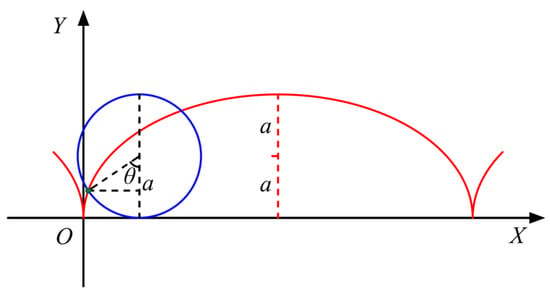
Figure 1.
Schematic diagram of the brachistochrone.
The brachistochrone has the property of reaching the end point the fastest. Inspired by the rapid convergence of the cycloid, the brachistochrone reaching law based on the cycloid function is designed as follows:
where is a strictly positive. The switching function in the conventional reaching law is replaced by the cycloid function. The centrosymmetric nonlinear function is constructed as follows:
where is a strictly positive. is a piecewise discontinuous function, and is the interval length of the symmetric linear segment of near the origin. The parameter——can be adjusted for different stages of according to design’s requirement.
The BRL divides the approaching process of SMC into two states. At the stage far from the SF, the exponential reaching law in [24] is adopted. The farther the distance from the SF, the greater the arrival rate, which can effectively and quickly pull the state variable close to the SF.
By observing the above laws, the common reaching law is generally observed to be faster when it is far from the SF, and it slows down when it approaches the SF. The nonlinear function, , is designed as brachistochrone in the interval . That is, when the state is near the SF, the reaching law obeys the brachistochrone so that the state variable approaches the SF. The designed nonlinear function is smooth and discontinuous. The parameters of the BRL can be adjusted according to the cycloid function to meet different requirements of the approach speed. When the state variable reaches the design range, it can reach the specified position in the shortest amount of time.
Near the origin, the smooth continuous function replaces the function in the reaching law, theoretically avoiding chattering in the control input. The cycloid has the characteristic of the shortest arrival time, and the end of the cycloid coincides with the desired line. Taking the brachistochrone as the reaching law, the time for approaching the SF can be shortened.
In order to further study the performance of BRL, CRL, PRL [33], ERL [34], and SPRL are selected as comparison objects in this paper. Of course, due to different structures for each approaching law, a completely fair environment cannot be set up. By analyzing the structure, we set similar gain values as far as possible, which can reflect the convergence performance of different approaching laws to a certain extent. The CRL is given by (8) with . The PRL is given by (10) with and . The ERL is given by (12) with , , , and . The SPRL is given by (15) with , and . Parameters of the BRL are set as and . The initial value of the simulation analysis is set to 6, and the results are shown in Figure 2.
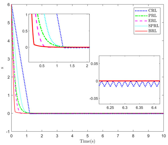
Figure 2.
Simulation of different reaching laws.
It is obvious from Figure 2 that the BRL has faster convergence speeds and converges more smoothly. More importantly, the chatter in the steady-state stage is effectively alleviated, while the convergence rate of the other four approaching laws is slow, and chattering still exists at the equilibrium point.
SMC is a type of variable structure control (VSC). In the control application of VSC, the state response of the system can be divided into three stages, namely reaching mode (RM), sliding mode (SM), and steady-state mode (SS). In practical applications, the switching of the VSC system rarely occurs on the switching plane. Therefore, the switching plane of the VSC system is called an ideal switching plane. For second-order systems, there are generally two acceptable sliding-mode state trajectories. Trajectories of type-I are ideal trajectories and type-II are trajectories with bandwidths. In this paper, a new control strategy is designed based on the type-I trajectory. In order to satisfy the two conditions of the type-I trajectory, the state is required to reach the switching plane at the switching time, and the natural dynamics of the object coincide with the ideal switching plane. A new reaching law is designed for the former condition, and for the latter, ESO is used to compensate the multi-channel’s uncertainty in the system in time. Reference [35] focuses on second-order non-linear discrete systems with matched disturbances. On the basis of the former, the control method proposed in this study has expanded applicability and can be applied to systems with mismatching disturbances.
3.2. Design of the Modified ADRC-SM
For system (1), the traditional SMC’s design is as follows.
- Step 1: Construct the error dynamics system
The tracking error is described as follows.
- Step 2: Construct a typical sliding surface—.
Select the control input, , that drives error vectors to reach the sliding surface.
- Step 3: Design the reaching law—.
- Step 4: Construct the Lyapunov function.
It is necessary that the designed reaching law satisfies (22).
- Step 5: Design control input—
According to the relation and condition of (18)–(20), the control input, , can be expressed in the following form.
After simplification, the control input can be expressed as follows.
Assumption 3.
There is a continuous function satisfying .
According to Assumption 3, inequality can be obtained. To ensure stability, equation must be satisfied, and the reaching law gain of the designed controller must be designed as , where is a very small positive number.
Equation (25) is decomposed as follows:
where
Considering that and are unknown, they cannot be explicitly expressed and computed in the control law. Assume so that all uncertainties in the original system (1) are bundled together and can be estimated uniformly. In order to compensate for the unknown perturbation while reducing computational complexities, a reduced-order ESO [36] is used to improve the control accuracy of the system.
For the second-order nonlinear system (1) using closed-loop controls, the existing state variables can be converted into measurable or computable error variables, and the error state equation is as follows.
Consider that both state as the derivative of and the second derivative of are computable. We can design a reduced-order ESO as follows to reduce unnecessary computational efforts:
where and are the gains that have to be designed for the reduced-order ESO and the estimation of the disturbance, respectively. Then, Equation (30) can be written as follows.
The results from the step 5 can be organized as follows.
Substituting (32) in (31) yields the following.
Thus, (33) is shortened to the following form.
Integrating both sides of Equation (34) yields the following.
Since , Equation (25) can be further expressed as follows.
3.3. Stability Analysis of the Proposed Controller
In this section, our main results are formulated. Firstly, we prove the convergence of reduced-order ESO. Then the stability convergence of the main controller based on the novel reaching law is provided.
By Assumption 2, the function and are first-order differentiable and their derivatives are bounded. From Equation (29), it can be known that the total disturbance, also satisfies the first-order differentiability, and its derivative is bounded. The error dynamics is Equation (29), and the corresponding reduced-order ESO is Equation (30). The subtraction can be obtained as follows.
The variable is introduced to make . It is simplified as follows.
The transfer function of the tracking error for the observer system is described as follows.
According to the final value theorem, the following can be obtained.
Equation (40) shows that the tracking error of the observer tracking disturbance will eventually converge to zero with time, which proves the stability of the reduced-order ESO.
In order to verify the stability of the modified ADRC-SM, the Lyapunov function is chosen as follows:
According to the stability standard, the controlled system is asymptotically stable when Equation (42) is established.
By combining Equations (20) and (38), we obtain the following.
According to the stability analysis of the previous observer, it can be concluded that . Obviously, there are three situations:
- (1)
- : where . Because of and , ;
- (2)
- : where , , ;
- (3)
- : where , , .
In conclusion, the new reaching law (15) satisfies the Lyapunov stability condition . In other words, the BRL designed in this work can ensure the reachability of the sliding mode motion of the system’s state. Since ESO has accurately estimated the perturbation, the estimation error, , is much smaller than perturbation . Therefore, the reaching law gain of the modified ADRC-SM can be designed to be much smaller than that of the traditional SMC, and the chattering phenomenon can be moderated to a certain extent, which will be demonstrated in subsequent simulation studies.
Theorem 1.
For (15), system states and tend to zero within a variable time . If , the upper limit of approaching time is . If , the approaching time is greater than zero and less than . The convergence time has an upper bound related to the initial value of the state-.
Proof of Theorem 1.
According to the initial value of the SF, the arrival time of the BRL can be divided into two cases, which are and :
- (1)
- .
When the initial value- of the sliding state is less than , according to Equation (15), the reaching law at this point is described as follows.
On the other hand, it could be written as follows.
Considering that Equations (44) and (45) are symmetric functions centered around (0,0), we can only consider one side.
Supposing is the arrival time of Equation (15) and , take and then ; we can obtain the following.
Substituting (43) into (46) yields the following.
Integrating both sides of Equation (47) provides us with the following equation.
Assuming and the initial condition is and substituting into (49), we obtain the following.
If , it should be noted that . Since leads to , in such cases, the reaching time is obtained as follows.
According to the range of , the following results can be obtained.
- (2)
- .
When is greater than , first reaches and then ; then, the total approach time is . According to (20), the expressions of and are as follows.
Therefore, when , the total reaching time is obtained as follows.
According to the range of , the following results can be obtained.
The method of selecting parameter in BRL is the same as the conventional reaching law. denotes the range of the brachistochrone. Obviously, the larger is, the smaller the approach time . A suitable can be selected according to design requirements. In practice, it is not possible to increase endlessly, and the physical limits of electronic components should also be considered. □
4. Simulation and Experiment
To verify the convergence characteristic and anti-interference of the controller proposed in Section 3, two sets of simulations and experiments are set up. In the first group, different reaching laws were used as a contrast; in the second group, the disturbances in different channels were used as contrast.
4.1. Simulation
Firstly, we selected two types of reference signals to testify the validity of the BRL by comparing other approaching laws, namely step and sinusoidal signals. The simulation was built on the Simulink platform, and the sampling time was fixed at 1 ms. The simulation time is set to 10 s. According to the parameters collected in Table 1, the response results of different approach laws without interference are shown in Figure 3, Figure 4, Figure 5 and Figure 6 and Table 2. Control objects are uniformly set as follows.

Table 1.
Parameters of the presented control algorithm.
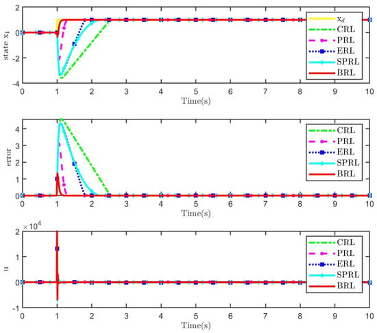
Figure 3.
Tracking results of different reaching laws under step signals.
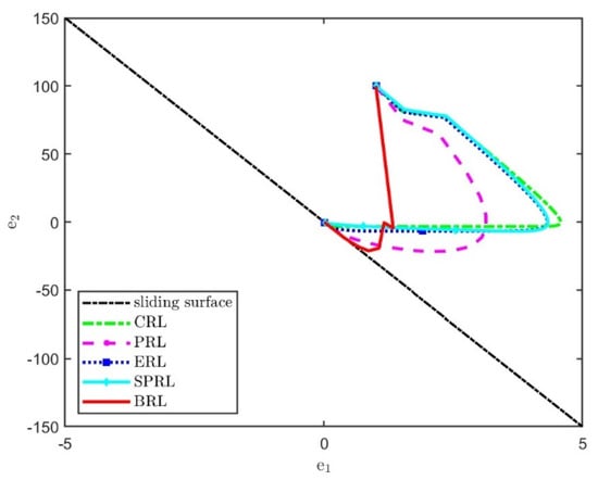
Figure 4.
Sliding mode motions for different reaching laws under step signals.
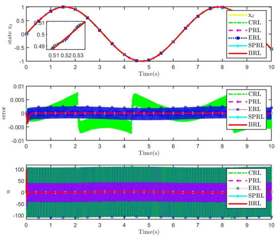
Figure 5.
Tracking results of different reaching laws under a sinusoidal signal.
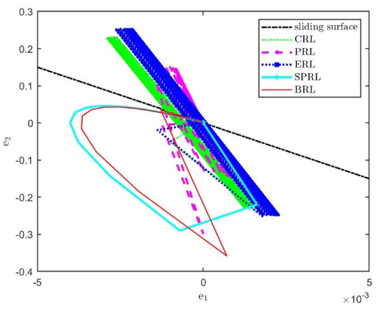
Figure 6.
Sliding mode motions for different reaching laws under sinusoidal signals.

Table 2.
Quantitative comparison of results of sinusoidal signals.
The results show that, under the step signal, the state of modified ADRC-SM based on the proposed BRL rapidly approaches the desired signal. Compared with other approaching laws, the overshoot is low. The phase diagram in Figure 4 shows that BRL has the shortest path to the sliding surface, ensuring a fast dynamic tracking response. Under the sinusoidal signal, the state of the controller based on the proposed BRL approaches the desired signal rapidly, and the error is small. The phase diagram in Figure 6 shows that BRL has the shortest path to the sliding surface without chattering. From the perspective of power consumption, the control input of BRL does not switch at high frequency, resulting in low energy consumption. The designed BRL ensures fast dynamic tracking responses and avoids input chattering in control signals.
It is obvious from Table 2 that several reaching laws eventually tend to become steady and track the desired attitude instructions accurately. By comparing the basic indexes of response tracking performance, it is found that the dynamic response of the proposed reaching law is slightly rapid, and the tracking error is reduced. In addition, the BRL can effectively eliminate chattering in both transient and static phases compared to the input chattering that occurs in conventional reaching laws, naturally yielding a weakened dissipation in control efforts.
To better demonstrate the capability of the designed control scheme in tackling matched and unmatched uncertainty, two case responses (with matched and with unmatched uncertainty) are implemented. At the same time, an unknown system dynamics estimator (USDE) [37] is introduced as a comparison object. The object model with matched uncertainty is uniformly set as (58) for simulation verifications, and the results are shown in Figure 7 and Figure 8. The object model with unmatched uncertainty was uniformly set as (59) for simulation verification, and the results are shown in Figure 9 and Figure 10. The controller parameters are collected in Table 3, including the initial conditions .
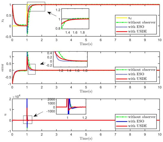
Figure 7.
Tracking results of the system with matched uncertainty under the step signal.
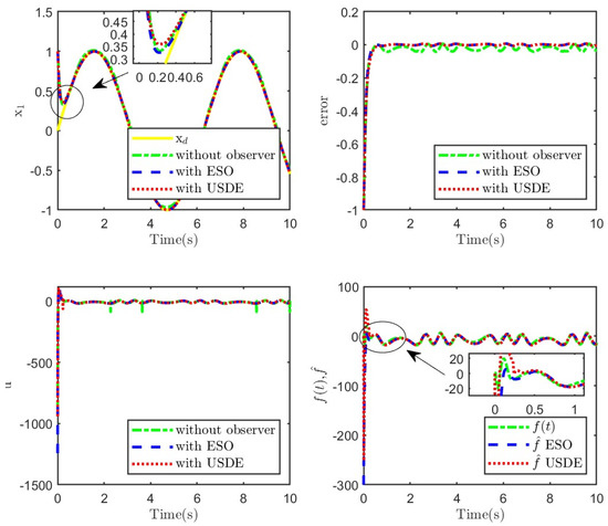
Figure 8.
Tracking results of the system with matched uncertainty under the sinusoidal signal.
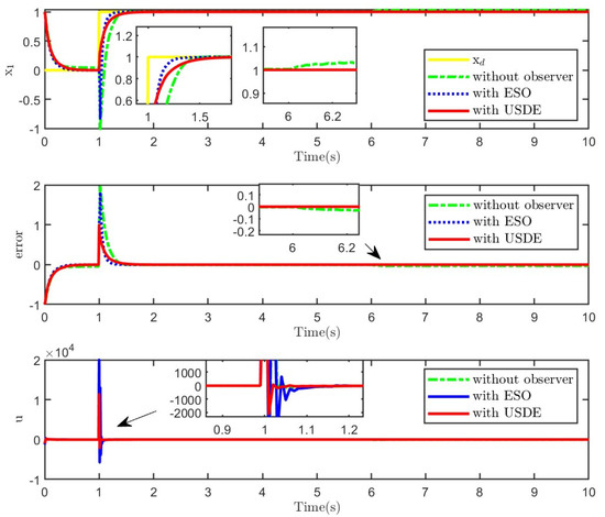
Figure 9.
Tracking results of the system with mismatched uncertainty under the step signal.
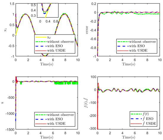
Figure 10.
Tracking results of the system with mismatched uncertainty under the sinusoidal signal.

Table 3.
Parameters of the presented control algorithm.
As observed from Figure 7, Figure 8, Figure 9 and Figure 10, both the modified ADRC-SM and SMC combined with USDE can achieve better responses with small tracking errors. In addition, from the perspective of step response, the modified ADRC-SM responds faster under the same parameters. In terms of sinusoidal responses, the modified ADRC-SM has a small overshoot of steady error and accurate estimation of unknown disturbances. Observed from Figure 8 and Figure 10, the tracking error of the controller with ESO or USDE is smaller than that without an observer. The results show that the modified ADRC-SM has good restraining effects on various uncertainties.
4.2. Experimental Verification
To further verify that our presented algorithm is effective, we perform a test on a six-joint robot. Figure 11 shows the experimental platform and the overall control system, with the joint module as the verification object. The motor drives the joints for rotary motions, and the equipment is equipped with torque sensors, incremental encoders, and absolute encoders. The absolute displacement of the joint is measured by an absolute encoder located behind the reducer. The PC is responsible for calculating the control inputs and transmitting the signals to the drive. Then, it drives the electronic driver, and the electronic driver finally realizes movements through the harmonic reducer and frameless motor. There are measurement errors and many uncertainties in the intermediate process. Kinetic equations and physical parameters in the experiment are referred to in [29].
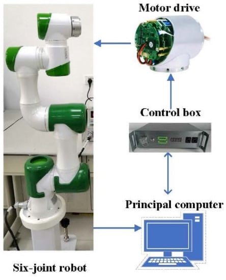
Figure 11.
The schematic of the autonomous experimental platform.
The fourth and fifth joints are selected as the experimental objects to verify the effectiveness and stability of the proposed controller in the joint space. The experiment was set up as two groups, and a comparison group was set up. In the first group, the conventional reaching law of SMC was introduced as the comparison object to testify the superior capability of the modified ADRC-SM based on the brachistochrone reaching law. The second group introduces USDE to compensate for multiple uncertainties and verifies that ADRC-SM based on brachistochrone can effectively control uncertain systems. The target is to schedule a control input as in the above section to ensure that the output of the system tracks a desired trajectory . The initial state of the system is set to = 0°, = 0°/s.
In order to facilitate comparison, the following performance indicators are introduced to quantitatively measure the performance of the control algorithm.
Figure 12 and Table 4 show group 1 of the experimental results. From the position response and tracking error of the two joints, the overshoot, fluctuation, and steady-state error of the proposed BRL are much smaller than those of the CRL. The tracking error is kept within a small range. In addition, the tracking error’s spike caused by friction is alleviated when the joint velocity crosses zero, which proves that the proposed controller is more accurate for disturbance compensation. In terms of control input, the BRL has large fluctuations in the early stage of motion, with fast response and periodic changes. However, the CRL has many peak fluctuations. Considering the coupling between the fourth and fifth joints, the moving fifth joint can be regarded as the external interference when the fourth joint is running. The tracking error based on the BRL is hardly affected by the fifth joint and remains within 0.5°, which proves that the proposed control strategy has better anti-disturbance than the CRL. Select the third period (stable period) to calculate the control performance indicators of the two joints, as shown in Table 4. Compared with the CRL, the average error and the maximum error of the BRL are significantly reduced, and the reduction ratio is nearly 80% and 70%, indicating that the tracking accuracy and disturbance suppression ability of the manipulator have been significantly improved. The superiority of the proposed reaching law is proved.
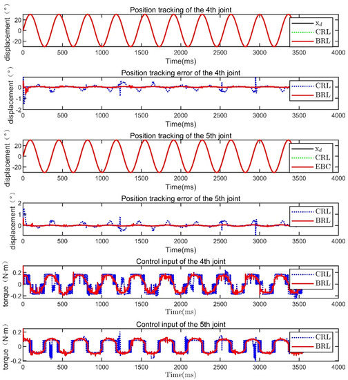
Figure 12.
Experimental comparative result in group 1.

Table 4.
Comparison results of controller performance indicators.
The tracking results and performance indicators of different observers are shown in Figure 13 and Table 5. According to the position response, both the modified ADRC-SM and SM-USDE can achieve better tracking, and the overshoot and fluctuation of the modified ADRC-SM are smaller than the SM-USDE. The error is maintained stably within a small range without fluctuation. The average tracking error of the modified ADRC-SM is 0.0033°, which is much smaller than 0.0067° of the SM-USDE. According to the control input, the modified ADRC-SM responds quickly and changes periodically, while many fluctuations occur in the SM-USDE. The tracking error of the fourth joint using the modified ADRC-SM is almost unaffected by the fifth joint, and the error remains within 0.5°, which proves that the proposed control strategy is more robust than the SM-USDE. The average tracking error and the maximum tracking error in the period of the modified ADRC-SM are both significantly smaller than those of the SM-USDE, and the reduction ratio is nearly 50% and 80%, indicating that the tracking accuracy and disturbance suppression ability of the manipulator have been significantly improved.
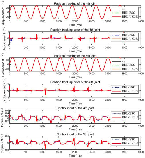
Figure 13.
Experimental comparative result in group 2.

Table 5.
Comparison results of controller performance indicators.
5. Conclusions
It is well known that one of the most challenging problems in control theories is the control of nonlinear uncertain systems. In this paper, a universal manifold of second-order nonlinear uncertain systems is provided, and a modified ADRC-SM is designed using the active disturbance rejection control framework. A novel reaching law is designed based on the cycloid function, which shortens the convergence time of the system. The proposed controller can theoretically achieve fast responses and eliminate chattering. The simulation mainly compares the dynamic response ability of the second-order system under different reaching laws and different observers. Experimental results showed that the modified ADRC-SM controller has bright tracking properties and can achieve accurate trajectory tracking under the influence of uncertainty. The new controller has the characteristics of possessing fewer parameters, more application instances, high precision, and simple operation, which is suitable for engineering applications. The analytical contribution of this study will help engineers obtain satisfactory control properties in the presence of disturbances in nonlinear uncertain devices.
Author Contributions
Conceptualization, D.Z. and T.W.; methodology, D.Z.; software, T.W.; validation, D.Z., T.W. and S.S.; formal analysis, D.Z.; investigation, D.Z.; resources, Z.D.; data curation, T.W.; writing—original draft preparation, D.Z.; writing—review and editing, T.W.; visualization, D.Z.; supervision, D.Z.; project administration, S.S.; funding acquisition, Z.D. All authors have read and agreed to the published version of the manuscript.
Funding
This research was funded by the Central Government Guided Local Special Foundation of China, grant number YDZX20191400002765; the National Natural Science Foundation of China, grant number 52075503; and the Key Program of Shanxi Province, grant number 201903D421006.
Acknowledgments
The authors acknowledge the North University of China for its administrative, financial, and technical support.
Conflicts of Interest
The authors declare no conflict of interest.
References
- Kayacan, E.; Ramon, H.; Saeys, W. Robust Trajectory Tracking Error Model-Based Predictive Control for Unmanned Ground Vehicles. IEEE/ASME Trans. Mechatron. 2016, 21, 806–814. [Google Scholar] [CrossRef]
- Sun, T.; Zhang, J.; Pan, Y. Active DIsturbance Rejection Control of Surface Vessels Using Composite Error Updated Extended State Observer. Asian J. Control 2017, 19, 1802–1811. [Google Scholar] [CrossRef]
- Ginoya, D.; Shendge, P.D.; Phadke, S.B. State and Extended Disturbance Observer for Sliding Mode Control of Mismatched Uncertain Systems. J. Dyn. Syst. Meas. Control 2015, 137, 074502. [Google Scholar] [CrossRef]
- Zhao, C.; Guo, L. Control of Nonlinear Uncertain Systems by Extended PID. IEEE Trans. Autom. Control 2021, 66, 3840–3847. [Google Scholar] [CrossRef]
- Chen, S.; Chen, Z. On Active Disturbance Rejection Control for a Class of Uncertain Systems With Measurement Uncertainty. IEEE Trans. Ind. Electron. 2021, 68, 1475–1485. [Google Scholar] [CrossRef]
- Huang, J.; Ri, S.; Fukuda, T.; Wang, Y. A Disturbance Observer Based Sliding Mode Control for a Class of Underactuated Robotic System With Mismatched Uncertainties. IEEE Trans. Autom. Control 2019, 64, 2480–2487. [Google Scholar] [CrossRef]
- Feliu, V.; Ramos, F. Strain gauge based control of single-link flexible very lightweight robots robust to payload changes. Mechatronics 2005, 15, 547–571. [Google Scholar] [CrossRef]
- Yang, J.; Zolotas, A.; Chen, W.H.; Michail, K.; Li, S. Robust control of nonlinear MAGLEV suspension system with mismatched uncertainties via DOBC approach. ISA Trans. 2011, 50, 389–396. [Google Scholar] [CrossRef] [Green Version]
- Qu, L.; Qiao, W.; Qu, L. An Extended-State-Observer-Based Sliding-Mode Speed Control for Permanent-Magnet Synchronous Motors. IEEE J. Emerg. Sel. Top. Power Electron. 2021, 9, 1605–1613. [Google Scholar] [CrossRef]
- Xu, L.; Shao, X.; Zhang, W. USDE-Based Continuous Sliding Mode Control for Quadrotor Attitude Regulation: Method and Application. IEEE Access 2021, 9, 64153–64164. [Google Scholar] [CrossRef]
- Zhang, J.; Guo, L. Theory and Design of PID Controller for Nonlinear Uncertain Systems. IEEE Control Syst. Lett. 2019, 3, 643–648. [Google Scholar] [CrossRef]
- Cho, H.; Kerschen, G.; Oliveira, T.R. Adaptive smooth control for nonlinear uncertain systems. Nonlinear Dyn. 2020, 99, 2819–2833. [Google Scholar] [CrossRef]
- Ling, S.; Wang, H.; Liu, P.X. Adaptive Fuzzy Tracking Control of Flexible-Joint Robots Based on Command Filtering. IEEE Trans. Ind. Electron. 2020, 67, 4046–4055. [Google Scholar] [CrossRef]
- Shiravani, F.; Shafiei, M.H. Robust Output Regulation of a Class of Nonlinear Systems Via Disturbance Observer in the Presence of Matched and Unmatched Uncertainties. J. Dyn. Syst. Meas. Control 2019, 141, 091007-1–091007-8. [Google Scholar] [CrossRef]
- Van, M. Higher-order terminal sliding mode controller for fault accommodation of Lipschitz second-order nonlinear systems using fuzzy neural network. Appl. Soft Comput. 2021, 104, 107186. [Google Scholar] [CrossRef]
- Kayacan, E. Sliding mode control for systems with mismatched time-varying uncertainties via a self-learning disturbance observer. Trans. Inst. Meas. Control 2018, 41, 2039–2052. [Google Scholar] [CrossRef]
- Ma, Q.; Qin, J.; Kang, Y.; Zheng, W.X. Fault-Tolerant Cooperative Tracking Control of Nonlinear Affine Systems Using Integral Sliding Mode Control. In Proceedings of the 2018 IEEE 27th International Symposium on Industrial Electronics (ISIE), Cairns, Australia, 13–15 June 2018; pp. 1137–1142. [Google Scholar]
- Rahmani, M.; Ghanbari, A.; Ettefagh, M.M. A novel adaptive neural network integral sliding-mode control of a biped robot using bat algorithm. J. Vib. Control 2016, 24, 2045–2060. [Google Scholar] [CrossRef]
- Yang, J.; Li, S.; Yu, X. Sliding-Mode Control for Systems With Mismatched Uncertainties via a Disturbance Observer. IEEE Trans. Ind. Electron. 2013, 60, 160–169. [Google Scholar] [CrossRef]
- Kayacan, E.; Fossen, T.I. Feedback Linearization Control for Systems with Mismatched Uncertainties via Disturbance Observers. Asian J. Control 2018, 21, 1064–1076. [Google Scholar] [CrossRef]
- Han, J. From PID to Active Disturbance Rejection Control. IEEE Trans. Ind. Electron. 2009, 56, 900–906. [Google Scholar] [CrossRef]
- Gao, Z. Scaling and bandwidth-parameterization based controller tuning. In Proceedings of the American Control Conference, Denver, CO, USA, 4–6 June 2003; pp. 4989–4996. [Google Scholar]
- Wang, F.; Liu, P.; Jing, F.; Liu, B.; Peng, W.; Guo, M.; Xie, M. Sliding Mode Robust Active Disturbance Rejection Control for Single-Link Flexible Arm with Large Payload Variations. Electronics 2021, 10, 2995. [Google Scholar] [CrossRef]
- Wang, H.; Pan, Y.; Li, S.; Yu, H. Robust Sliding Mode Control for Robots Driven by Compliant Actuators. IEEE Trans. Control Syst. Technol. 2019, 27, 1259–1266. [Google Scholar] [CrossRef]
- Gao, W.; Hung, J.C. Variable structure control of nonlinear systems: A new approach. IEEE Trans. Ind. Electron. 1993, 40, 45–55. [Google Scholar] [CrossRef]
- Wang, A.; Jia, X.; Dong, S. A New Exponential Reaching Law of Sliding Mode Control to Improve Performance of Permanent Magnet Synchronous Motor. IEEE Trans. Magn. 2013, 49, 2409–2412. [Google Scholar] [CrossRef]
- Wang, Y.; Feng, Y.; Zhang, X.; Liang, J.; Cheng, X. New Reaching Law Control for Permanent Magnet Synchronous Motor With Extended Disturbance Observer. IEEE Access 2019, 7, 186296–186307. [Google Scholar] [CrossRef]
- Liu, J.; Vazquez, S.; Wu, L.; Marquez, A.; Gao, H.; Franquelo, L.G. Extended State Observer-Based Sliding-Mode Control for Three-Phase Power Converters. IEEE Trans. Ind. Electron. 2017, 64, 22–31. [Google Scholar] [CrossRef] [Green Version]
- Wu, T.; Shi, S.; Zhang, D.; Shao, X. On backstepping control for a class of multiple uncertain systems with reduced-order ESO. Int. J. Control 2021, 1–12. [Google Scholar] [CrossRef]
- Na, J.; Li, Y.; Huang, Y.; Gao, G.; Chen, Q. Output Feedback Control of Uncertain Hydraulic Servo Systems. IEEE Trans. Ind. Electron. 2020, 67, 490–500. [Google Scholar] [CrossRef]
- Zhao, C.; Guo, L. PID controller design for second order nonlinear uncertain systems. Sci. China Inf. Sci. 2017, 60, 022201. [Google Scholar] [CrossRef] [Green Version]
- Hung, J.Y.; Gao, W. Variable structure control: A survey. IEEE Trans. Ind. Electron. 1993, 40, 2–22. [Google Scholar] [CrossRef] [Green Version]
- Fallaha, C.J.; Saad, M.; Kanaan, H.Y.; Al-Haddad, K. Sliding-Mode Robot Control with Exponential Reaching Law. IEEE Trans. Ind. Electron. 2011, 58, 600–610. [Google Scholar] [CrossRef]
- Mozayan, S.M.; Saad, M.; Vahedi, H.; Fortin-Blanchette, H.; Soltani, M. Sliding Mode Control of PMSG Wind Turbine Based on Enhanced Exponential Reaching Law. IEEE Trans. Ind. Electron. 2016, 63, 6148–6159. [Google Scholar] [CrossRef]
- Weibing, G.; Yufu, W.; Homaifa, A. Discrete-time variable structure control systems. IEEE Trans. Ind. Electron. 1995, 42, 117–122. [Google Scholar] [CrossRef]
- Tian, G. Reduced-Order Extended State Observer and Frequency Response Analysis; Cleveland State University: Cleveland, OH, USA, 2007. [Google Scholar]
- Yang, J.; Na, J.; Yu, H.; Gao, G.; Wang, X. Unknown System Dynamics Estimator for Nonlinear Uncertain Systems. IFAC-Pap. 2020, 53, 554–559. [Google Scholar] [CrossRef]
Publisher’s Note: MDPI stays neutral with regard to jurisdictional claims in published maps and institutional affiliations. |
© 2022 by the authors. Licensee MDPI, Basel, Switzerland. This article is an open access article distributed under the terms and conditions of the Creative Commons Attribution (CC BY) license (https://creativecommons.org/licenses/by/4.0/).