1. Introduction
Antennas with a high gain are essential for telecommunications links to operate at a high data rate. Additionally, antennas with a broad beam are required to support the transceivers’ high mobility [
1] and wireless transmission energy systems [
2]. However, as the beam expands, the gain of the antenna drops. As a result, a two-dimensional scanning antenna with a high gain is required. Two-dimensional scanning of space can be accomplished in a variety of ways, including mechanical scanning and scanning with a phased array antenna [
3]. There are a number of desirable design parameters in two-dimensional space scanning structures, including high gain, wide scanning angle (wide beam), high scanning speed, low weight, and reasonable cost. In mechanical scanning, due to the physical rotation of the antenna, the scanning speed is very low, and the general structure of the antenna is very bulky and expensive [
4,
5]. In phased array antennas, the scan speed is much faster than in the mechanical scan mode, but each element has a TR module, which leads to increased costs, high volume, and structure complexity. The phased array antenna also needs control and signal processing algorithms to work properly [
3,
6]. Therefore, inexpensive, low-complexity, light, and reliable structures are required for telecommunications applications.
Multibeam antennas are considered a suitable alternative for this topic. While 2D beam steering in multibeam antennas is necessary for the same functionality as phased array antennas, all work so far has focused only on one-dimensional beam scanning [
7,
8,
9]. The purpose of this study was to design an array antenna with 2D beam scanning capabilities to establish a connection between the satellite and a moving transceiver. Current communication systems employ multibeam antenna arrays and analogue or digital beamforming networks (BFNs) to simultaneously generate several beams at various angles. Analog BFNs are typically constructed utilizing power dividers, directional couplers, mixers, phase shifters, and transmission lines. These analogue BFNs are less costly and easier to build than their digital counterparts. The Butler matrix and Rotman lens are two examples of analogue BFNs [
10,
11]. The Rotman lens is preferred over alternative microwave lens topologies because of its flexibility, simplicity, and true latency characteristics, as well as its ability to be connected to linear arrays [
12,
13]. A Rotman lens [
12] is a device that passively changes the phase of a wave by propagating it into the open space between two parallel plates with a specified geometry. The lens outputs is used to power an antenna array in a linear array configuration. By adjusting the offset of the waves that reach the cluster, the antenna’s radiating lobe can be steered in a desired direction.
The usage of traveling wave structures has been demonstrated [
14,
15] for scanning the second spatial dimension. The leaky-wave antenna is an excellent choice in this area. It is desirable to employ leaky-wave-antenna configurations that are easy to fabricate, lightweight, and that have low loss in the KU band based on SIW technology. In the field of SIW LWAs, there are four types: uniform [
14,
15], quasi-uniform [
16,
17,
18], composite right-/left -handed (CRLH) [
19,
20], and periodic [
21,
22]. This form of SIW LWA has a radiation element evenly distributed along the direction of wave propagation within the substrate [
14,
15]. Structures in the quasi-uniform SIW LWA have spacing intervals that are smaller than the wavelength [
16,
17,
18]. Both SIW LWAs work on the fundamental space harmonics, where the fast wave travels inside the substrate. In order to avoid broadside radiation, these structures can be employed for beam scanning in the forward quadrant. One of the most important features of LWAs is the beam scanning range. The scanning of a beam from back to front is required in many applications. The CRLH and periodic LWAs allow backward-to-forward beam scanning, unlike the two previous varieties of SIW LWAs. Therefore, if we want to achieve the two-dimensional scanning of a space at wide angles, we must use several SIW leaky-wave antennas (SIW LWA CRLH and periodic) to scan one dimension and a Rotman lens to scan the other dimension.
In this study, first the SIW LWA and periodic, and then the appropriate Rotman lens, were designed to scan two-dimensional space. The simulation and measured results were compared to verify the designed structure. In
Section 2, first SIW LWA and then Rotman lens are designed for suitable two-dimensional special scanning. In
Section 3, the experimental results are presented and discussed. Finally, the conclusion is drawn in
Section 4.
2. Antenna Design
In this section, in the first step, an SIW LWA was designed to scan negative to positive one-dimensional angles. Then, to make the antenna multibeam, a Rotman lens with five inputs, eight dummy loads, and five outputs was designed to scan the negative to positive angles in the second dimension. Finally, five antenna elements were proposed, along with the Rotman lens.
2.1. Leaky Wave Antenna Design
The purpose of this part of the study was to design a suitable structure for frequency scanning in the theta direction with the ability to cover negative to positive angles. Traditional structures introduced in the literature [
14,
15] can only scan positive angles due to their structures. To scan the negative-to-positive angles, periodic structures with SIW-based radiation slots with a discontinuity in the waveguide width are used.
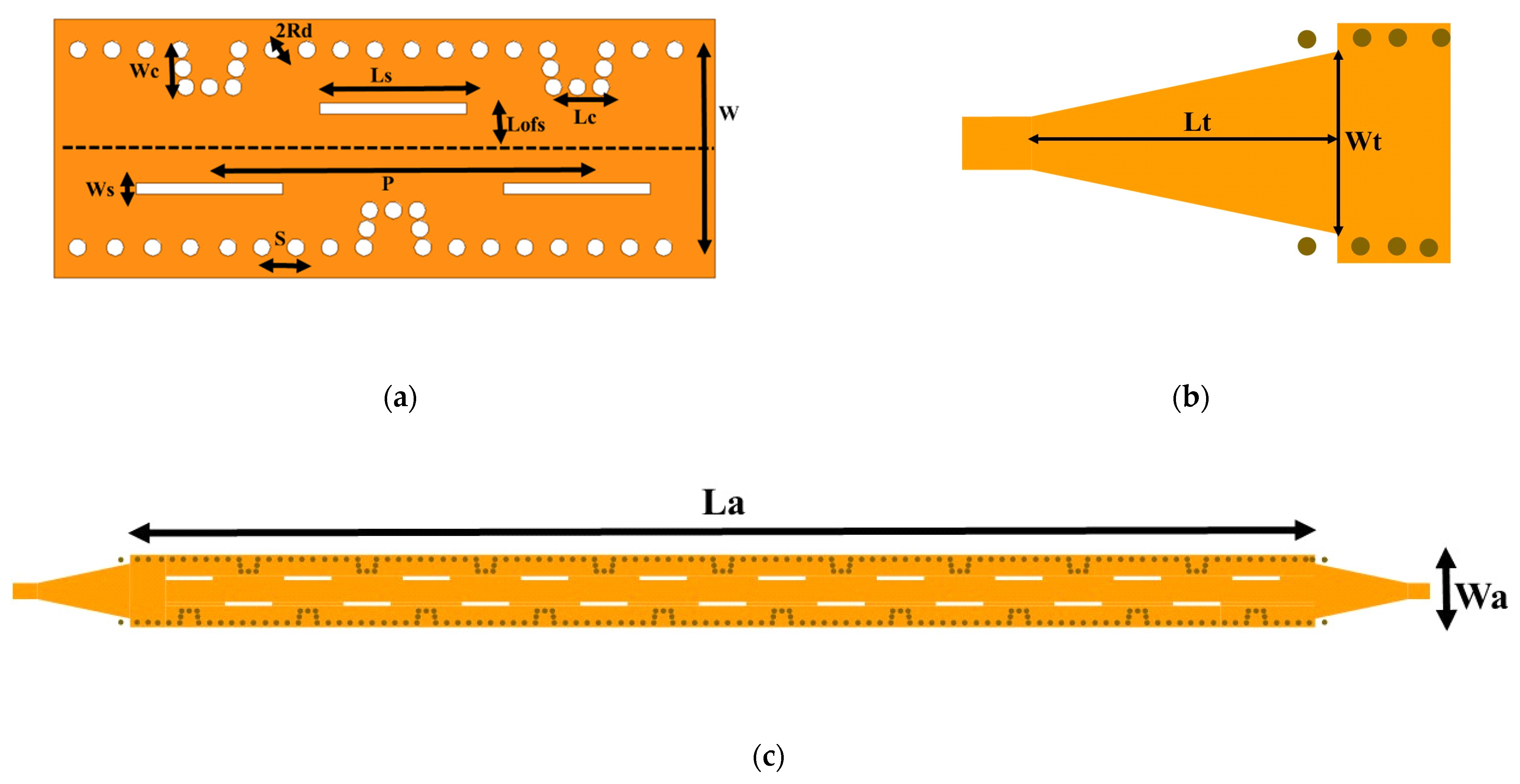
In this study, an LWA structure with 19 slot elements (shown in
Figure 1c) was used in order to scan the space in one dimension in the theta direction.
The phase constant of the
nth space harmonic is related to the direction of the main beam in a periodic LWA in the following manner [
15]:
It is evident that the frequency alters the main beam’s direction, hence enabling the frequency beam-scanning capabilities.
One drawback of SIW LWA is the resonance in the central frequency because, by changing the width of the waveguide using the impedance matching technique, the destructive effect of open stopband (OSB) can be removed [
15,
23,
24].
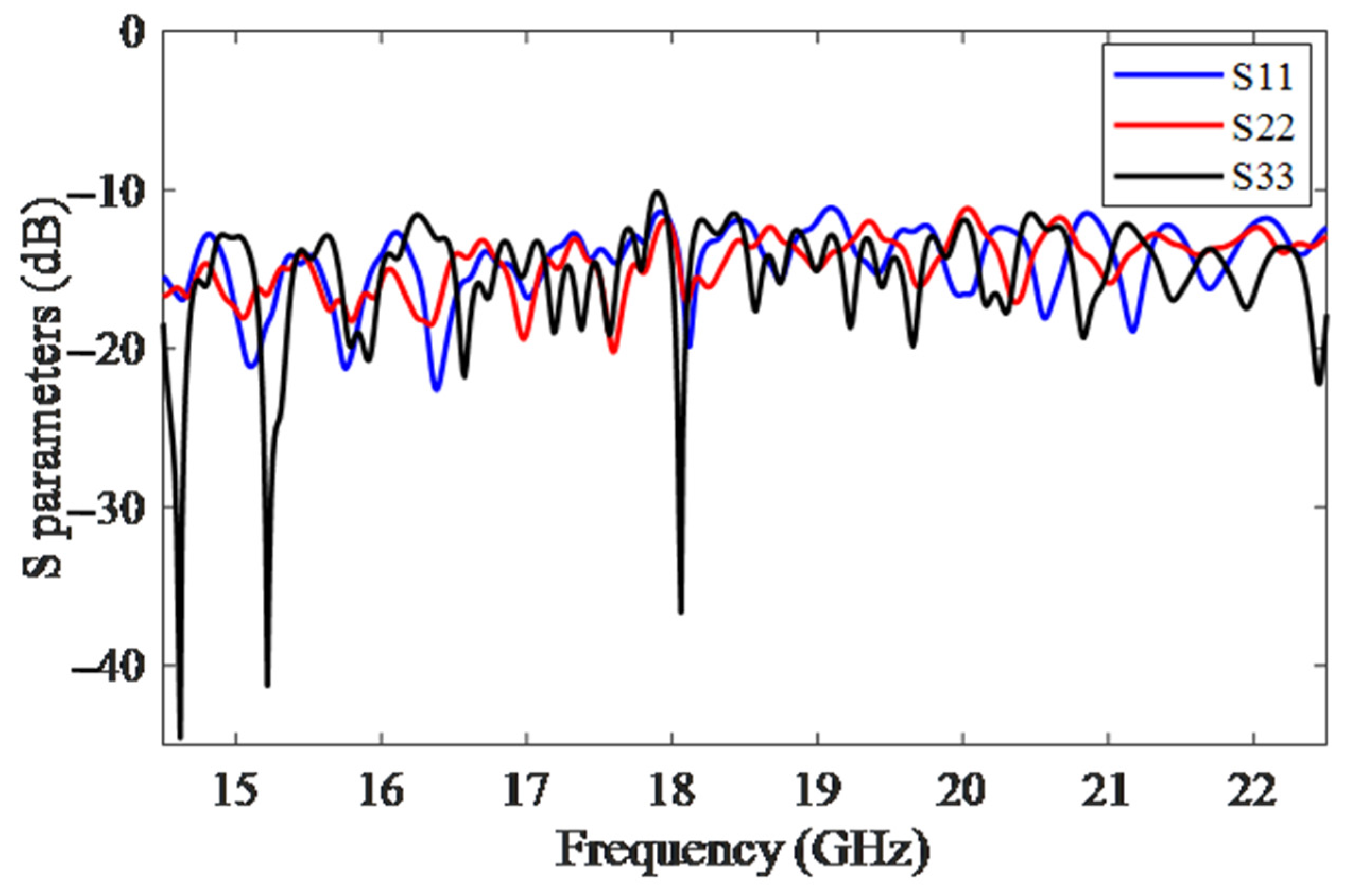
In
Figure 1a, the structure of a cell unit with the period of p is presented. The dimensions of the proposed SIW LWA structure are presented in
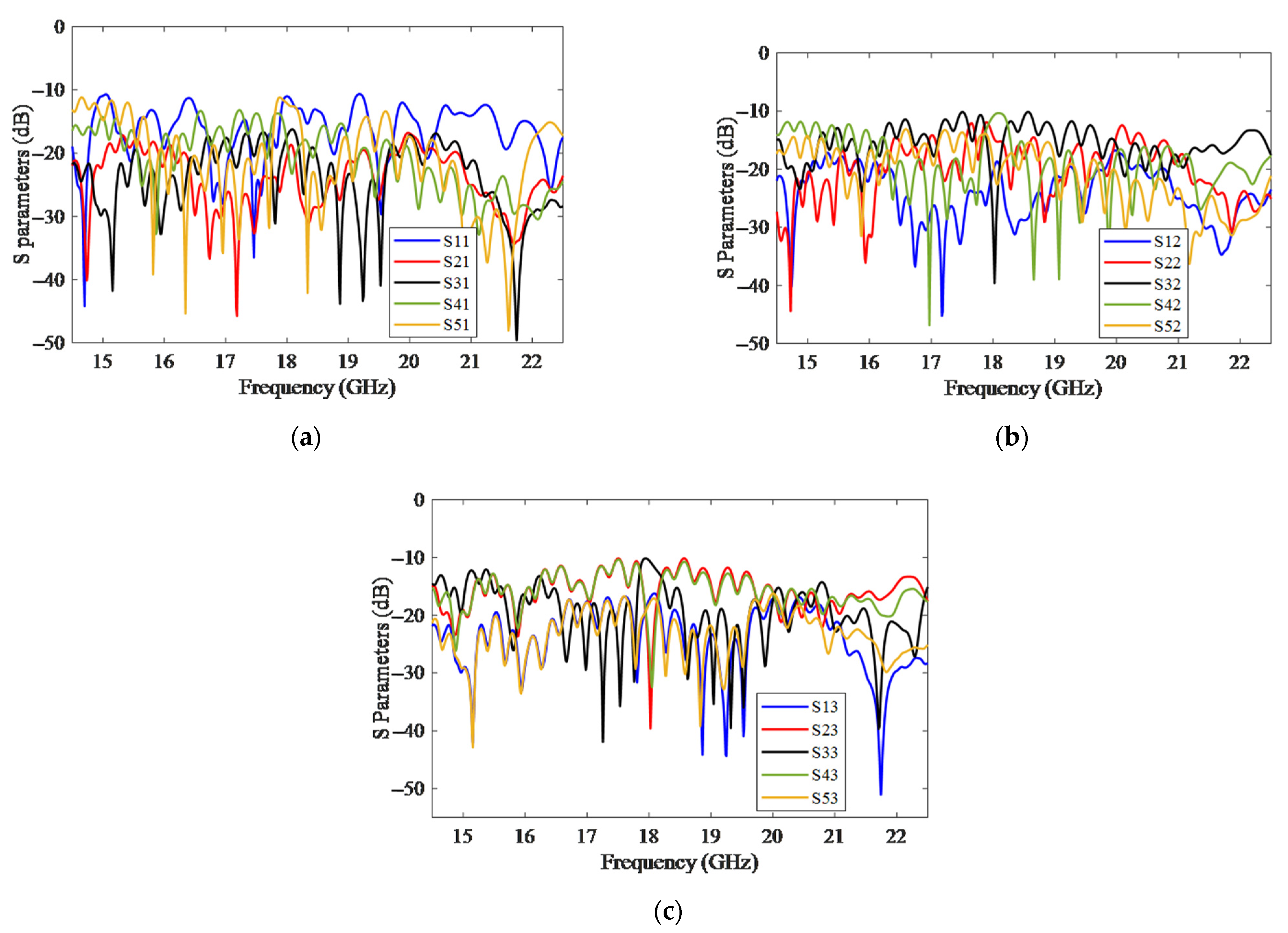
Table 1. The simulation S parameters are presented in
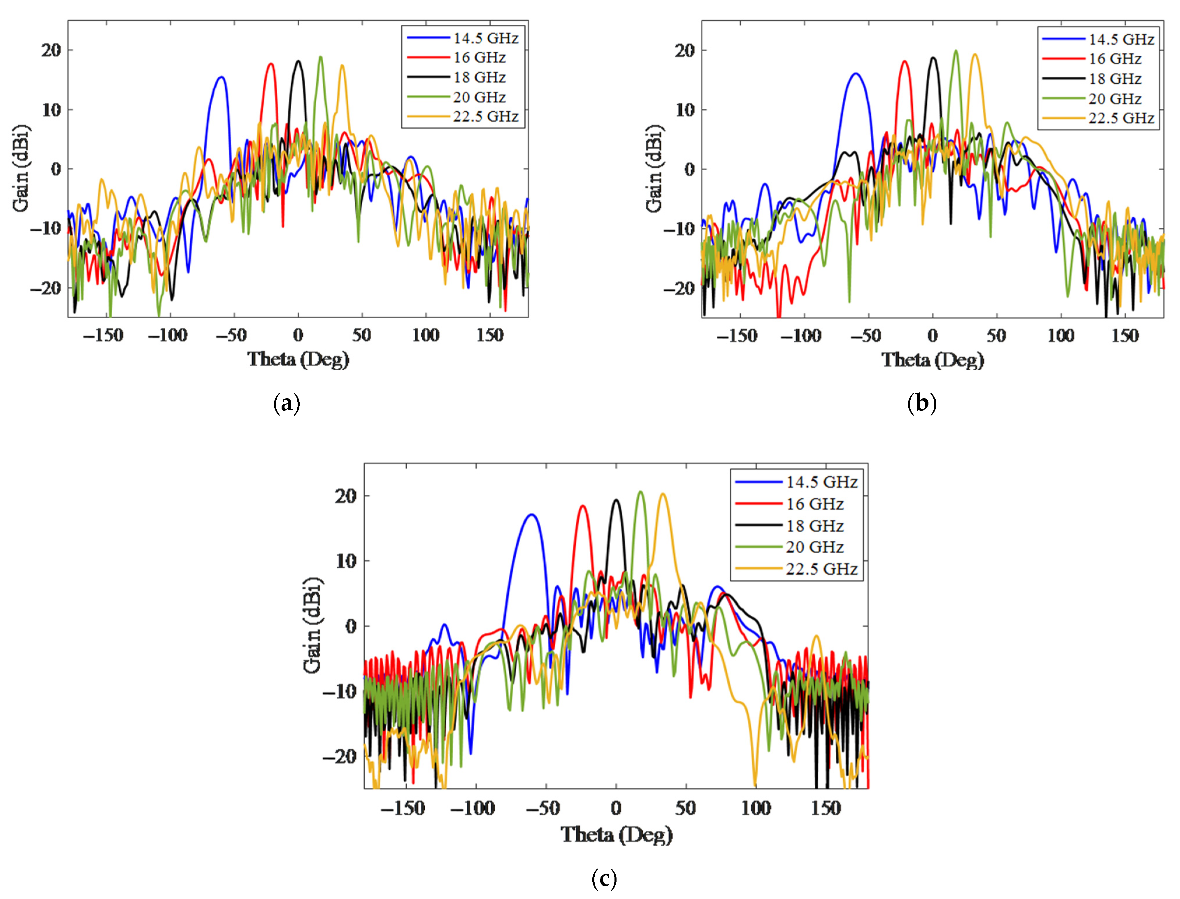
Figure 2, which shows that by placing the H-plane step discontinuity, the destructive effect of OSB is eliminated, and, as a result, the amount of return losses in the total bandwidth is less than −10 dB. At frequencies above 22.5 GHz, port 2 loses its loading effect and causes distortion in the pattern, which limits the frequency band. The simulation pattern of SIW LWA is reported for five frequencies in
Figure 3. According to this figure, by changing the frequency in the range of 14.5–22.5 GHz, the beam direction varies from −60 to +35 degrees in the direction of theta. At low frequencies, the HPBW pattern is wider due to a lower gain of the antenna than at high frequencies.
2.2. Rotman Lens Design
The aim in this part of the study was to scan the space in the phi direction using passive elements for an array antenna. A suitable phase shift between the array antenna’s elements is required to scan the space and rotate the beam. Here, such a function is also required to scan space along the horizon (
φ). Phase shifters’ structures are not suitable for changing the phase in the wide frequency band. One of the solutions to this problem with the lowest cost and best performance in broadband bandwidth is the Rotman lens [
12,
25]. The other advantages of the Rotman lens are that it is completely passive, has a wide scanning angle, and has a fast scanning speed with high gain. In a Rotman lens, the correct phases are applied to the output ports based on the length of the path [
26]. The typical Rotman’s study [
12] assumes that the beam and inner receiving outlines are circular. Hansen [
27] designed with an elliptical beam contour to cut down on the path length error.
According to
Figure 4, the Rotman lens has three parts: the focal arc, inner contour, and outer contour. The input ports are connected to the focal arc, and the output ports are connected to the outer contour. The dummy ports are used to improve the inter-port isolation and reduce the reflection from the sidewalls.
Here, a Rotman lens with five input ports, five output ports, and eight dummy ports was designed in the frequency range of 14.5–22.5 GHz with a scanning angle of −30 to +30 degrees. As shown in
Figure 4, designing a Rotman lens requires the parameters on-axis focal length (
f1), off-axis focal length (
f2), focal angle (
α), array beam angle (
φ), and element spacing in the array (
d).
According to the geometric shape of a Rotman lens, in order to have proper output phases,
w could be determined from Equation (1) [
27]:
where
a,
b, and
c are given as follows:
where
N indicates the number of elements from the lens’ axis. In order to have consistency in receiving a signal in the direction of phi from −30 to +30 degrees, it is essential to have overlap in the 3 dB points of multibeam patterns. Therefore, according to the above equations, a Rotman lens with 5 input ports, 5 output ports, and 8 dummy ports in the frequency range of 14.5–22.5 GHz was designed, as shown in
Figure 5. The input and output ports of the Rotman lens are called beam ports and array ports, respectively. To design the Rotman lens, 5 main parameters are needed, which are
f1 = 83 mm,
f2 = 75 mm,
α = 30 degrees,
φ = 30 degrees, and
d = 8.5 mm. Moreover, in our design and implementation, Ro4003 substrate with a thickness of 32 mil was used.
Figure 6 shows the relative phases of array ports for the excitation of different input ports (beam ports) at different frequencies. Due to the symmetry of the shape, the excitation response of port beams 4 and 5 is equivalent to the excitation of port beams 2 and 1. It can be observed (
Figure 6a,b) that the relative phase of the output array port changes with a constant slope at each frequency. Because the circuit is symmetric with respect to the excitation port 3, as shown in
Figure 6c, the relative phase slope of the output array port at each frequency is almost zero, which indicates the correct functionality of the proposed Rotman lens.
2.3. Two-Dimensional Multibeam SIW LWA
After designing the elements and the Rotman lens, a combination of SIW LWA elements with the Rotman lens was used to scan the space in 2D. As shown in
Figure 7, five SIW LWAs elements were combined with a Rotman lens. To avoid grating lobe with a scan angle of ±30 degrees, the distance between the array antenna elements had to meet Equation (5) [
27], which, by substituting
λ_min = 13.3 mm and
φ_max = 30 degrees, we achieved
d < 8.9 mm.
In order to maintain the desired phases at the input of a 5-element linear array, 5 transmission lines with the same length of 18 mm were used at the output of the Rotman lens. Considering that the array ports 1 and 5 had more distance from the linear array compared with the other array ports, a direct transmission line was used. However, for the array ports 2, 3, and 4, a curved transmission line was used to maintain the same length and phase.
The output of these five SIW LWA elements was connected to match loads. There as then a planar 2D-MBA capable of scanning space in the φ direction by exciting the lens’ beam ports and scanning in the θ direction by changing the frequency of the SIW LWA.
The simulated S parameters of the 2D-MBA are reported in
Figure 8, for the excitation of beam ports 1, 2, and 3. The results for the excitation of beam ports 4 and 5 were similar to those of beam ports 2 and 1 due to the symmetry of the structure. The simulation results also showed that all S parameters were below −10 dB in the frequency range of 14.5–22.5 GHz.
The 2D-MBA simulated gain for beam excitation of ports 1 to 5 at the boresight frequency (18 GHz) is reported in
Figure 9, showing the scanning in the direction of
φ angle between −30 and +30 degrees was achieved. Because 5 array antennas were used in the phi direction, the beam was wider in the phi direction than in the theta direction, which used 19 slot elements for frequency scanning.
The simulated gain of the 2D-MBA in the theta direction at different frequencies is shown in
Figure 10. Sections (a) through (c) are expressed for the excitation of ports 1, 2, and 3, respectively. The results of the excitation of beams ports 4 and 5 were similar to those of beam ports 2 and 1 due to the symmetry of the structure. According to these figures, by changing the frequency across the whole bandwidth, the theta angle was scanned between −60 and +35 degrees. In this structure, as the frequency increased, the gain increased and the 2D-MBA beam narrowed.
Figure 11 shows a two-dimensional scanning of the space for HPBW overlap. In this structure, the entire desired space was scanned in two dimensions using 60 patterns. These points are shown from p1 to p60 in the direction of the arrow movement in
Figure 11. As shown in this figure, this two-dimensional scanning of the space was performed by changing the beam ports in the phi direction and changing the frequency in the theta direction. The peak points of these 60 patterns for different ports and different frequencies are reported in
Table 2.
When moving in the positive theta direction, the frequency increased, which, in turn, increased the 2D MBA gain. In other words, the 2-D MBA pattern narrowed, so to fully cover the space, the points in
Figure 11 are close together. When moving in the negative theta direction, the frequency decreased and, as a result, the gain decreased and the 2D MBA pattern widened, so the distance between the points in
Figure 11 widen to completely cover the space.
3. Experimental Verifications
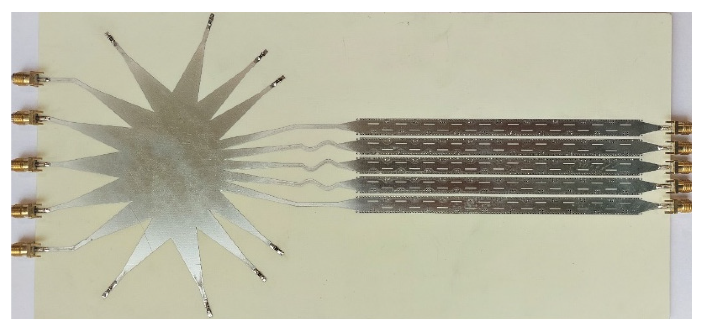
In this part of the study, the final 2D-MBA structure that was already simulated in CST software, Dassault Systèmes, Framingham, United States, was prepared for fabrication using Altium software on a PCB circuit board. The MBA was implemented on RO4003 substrate with ɛ
r = 3.55 and 32 mil thickness as shown in
Figure 12. The overall size of the structure was 280 × 140 mm.
Figure 13 displays the measured return losses of 2D-MBA for ports 1, 2, and 3. We observed that across the whole bandwidth, the measured return losses for the mentioned inputs were below −10 dB, which indicated the correct functionality of the proposed 2D-MBA by exciting each port. In addition, the return losses shown in this figure are close to what was predicted in
Figure 8.
Figure 14 shows the measured 2D-MBA gain for the excitation of different ports at a frequency of 18 GHz, which indicates scanning in the direction of the Phi angle between −30 and +30 degrees, and has a good agreement with the simulated results in
Figure 9. In addition, as moving from the middle port (Beam port 3) to the side ports, the measured 2D-MBA gain slightly dropped, and the highest gain was achieved in the boresight direction.
Figure 15 shows the measured 2D-MBA gain for the excitation of each of ports 1, 2, and 3 at five different frequencies, which are demonstrated in a, b, and c, respectively. By changing the frequency over the entire bandwidth, the theta angle between −60 to 35 degrees was scanned, which indicated the correct operation of SIW LWAs.
We observed that at a frequency of 14.5 GHz, 2D-MBA scanned the theta angle of −60 degrees, and as the frequency increased to a frequency of 22.5 GHz, it covered the theta angle of +35 degrees with a higher gain and a narrower pattern. In addition, as demonstrated in
Figure 15a–c, for a constant frequency, the 2D-MBA gain decreased by moving to the excitation of the side beam ports. In this case, the highest gain belonged to the beam port 3 excitation, which indicated the correct operation of the 2D-MBA structure and its agreement with
Figure 14. Finally, according to
Figure 14 and
Figure 15, which are in good agreement with the simulation results in
Figure 9 and
Figure 10, we concluded that the 2D space was scanned from −30 to +30 degrees in the phi direction and from −60 to +35 degrees in the theta direction.
4. Conclusions
In this study, a 2D-MBA was designed and built for two-dimensional space scanning. The test results showed that the LWA SIW could achieve a 95-degree beam scanning in the theta direction by changing the frequency from 14.5 to 22.5 GHz. Moreover, in the direction of phi, using a Rotman lens and five SIW LWAs, five beams were formed at a 60-degree angle of view. These five beams intersected at a 3 dB theta angle, so no disconnection in link occurred while scanning the space. Using 60 patterns, two-dimensional scanning of the space was obtained in the phi direction from −30 to +30 degrees and in the theta direction from −60 to +35 degrees. The measured S parameters revealed that the return losses and coupling between different beam ports were both less than −10 dB, achieving a radiation efficiency of 70%. This structure was made as a planar structure and built on Ro4003 substrate, which makes it easier to build.


