Article

Design of Miniaturized Antipodal Vivaldi Antennas for Wideband Microwave Imaging of the Head

1
Department of Electrical and Electronic Engineering, East West University, Dhaka 1212, Bangladesh
2
Department of Electrical and Computer Engineering, University of Central Florida, Orlando, FL 32816, USA
*
Author to whom correspondence should be addressed.
Electronics 2022, 11(14), 2258; https://doi.org/10.3390/electronics11142258
Submission received: 31 May 2022 / Revised: 7 July 2022 / Accepted: 11 July 2022 / Published: 20 July 2022
(This article belongs to the Special Issue New Generation Design of Antennas)

Abstract

:
Many wideband applications, e.g., microwave imaging of the head, require low-frequency (~1–6 GHz) operation using small antennas. Vivaldi antennas are extensively used in multifarious wideband applications; however, the physical dimensions of the antenna become very large for covering low-frequency bands. Hence, the miniaturization of Vivaldi antennas, while maintaining proper matching and radiation characteristics, is essential for these applications. In this work, two miniaturized Vivaldi antennas are proposed, and several miniaturization techniques are presented for reducing the size of the antennas without the need for being immersed into any matching liquid, while maintaining desired performance. The novelty of the designs lies in the use of two half-cut superstrates, which help in achieving low-frequency operation with end-fire radiation. Two prototype antennas are fabricated, and the performances of the antennas are analyzed from both simulation and measurement results. The antennas show an FBW of 45.26% and 95.9% with a gain of ~1.9–5.2 dB and ~1.5–5.5 dB, respectively, while having a radiation efficiency above 80% within the resonant bandwidth. A comparison of the proposed antennas with several other state-of-the-art Vivaldi antennas is included to demonstrate the viability of the proposed antennas in achieving the desired performance with comparatively small dimensions.

1. Introduction

Vivaldi antennas can offer a wide operational bandwidth and a high gain, and, hence, they are extensively used in many communication, sensor, telemetry, and medical applications such as high data rate signal transmission, microwave imaging, etc. The operating frequency range can be easily controlled by scaling the antenna’s physical dimensions. However, as per the basic design principles, the size of the antenna needs to be very large to operate at low frequencies. Hence, the miniaturization of the antenna is necessary in many applications, such as sensing, biomedical imaging, flush mounting on aircrafts, etc., where low-frequency operations are required. The desired application of this work is the microwave imaging of the head for the detection of anomalies such as blood clots.
The design of miniaturized antennas working for a wide range of frequencies requires the meticulous consideration of several performance parameters such as the gain, directivity, sidelobe level, etc. Several works have been laid forth to enhance the gain and reduce the backward radiation of the antenna while maintaining wideband operation [1,2,3,4,5,6,7,8,9]. In [1], the uniplanar compact electromagnetic band gap (UC-EBG) structure is used to reduce the backward radiation and achieve a higher gain and directivity. The use of the frequency selective surface (FSS) is shown in [2] for gain stability over a wide band of operating frequencies and for the suppression of radiation in undesired directions. Notable endeavors have been made with the concept of metamaterials for the gain enhancement of wideband antennas by means of double negative (DNG) or zero-index metamaterials (ZIM) [3,4,5,6,7,8,9]. Though high-gain UWB antennas can be useful for applications such as ground penetrating radar (GPR) [10], they might cause adverse effects due to the enhanced heating/absorption of radiation with a high gain in applications such as the microwave imaging of biomedical tissues [6]. Hence, considering the increasing design complexities and the requirements of the intended application, these techniques of using UC-EBG, FSS, or metamaterials are not adopted in this work.
A major design challenge of the Vivaldi antenna is that reducing the antenna size distorts the radiation pattern in low frequencies. Many methods have been proposed [11,12,13] to reduce the size of the antenna while keeping end-fire radiation characteristics. The use of surface corrugations is an effective tool to control the radiation characteristics of an antenna [14], even after the size reduction. Several works [12,15,16] have used a corrugated surface design for antenna miniaturization. However, there is a constant need for smaller dimensions and further reduction of the operating frequency. In some designs, the immersion of the antenna into matching or coupling liquid has been proposed and practically demonstrated for providing better matching with a smaller antenna size [17,18,19]. However, coupling liquid may impose some critical drawbacks, restricting its applicability [20]. For example, in the case of microwave imaging-based applications, it is not always possible to find suitable patient-specific dielectric properties of the matching liquid. Furthermore, the signal power level might get significantly attenuated due to the increased loss while propagating into the matching liquid.
In this paper, two miniaturized antipodal Vivaldi antennas have been proposed that can provide a wide bandwidth and end-fire radiation characteristics at low frequencies (~1–6 GHz) without the presence of a matching liquid. The performances of the proposed antennas have been analyzed in terms of the reflection coefficient, gain, and far-field radiation pattern. The effects of some critical physical design parameters of the antennas on the performance have been analyzed. Furthermore, the proposed antennas have been compared with several state-of-the-art Vivaldi antennas to demonstrate the effectiveness of the antennas.

2. Principles and Techniques of Designing Vivaldi Antennas

As demonstrated in [21], Vivaldi antennas have the prospects to offer a very wide bandwidth (theoretically infinite) in terms of both impedance and gain. Practically, the frequency range of operation of the Vivaldi can be designed by changing the geometry of the flare (taper profile) and the size of the antenna itself.
At the low-frequency end of the operation, the antenna works as a resonant antenna, where the resonant frequency depends on the width of the antenna. The width (W) of the antenna (or taper’s opening) should be at least half of the effective wavelength (λmax) at the lowest operating frequency in order to ensure effective radiation [22]. On the other hand, some research has suggested that the depth of the taper should not be less than one wavelength at the lowest frequency of operation [23]. Based on these criteria, for operating at low microwave frequency ranges (~1–6 GHz), the antenna dimensions need to be very large. At high frequencies, the antenna works as a traveling wave radiator, and its operation depends upon the feeding structure. The antipodal Vivaldi structure proposed in [24] utilized a low impedance tapered transition from the microstrip to a symmetric double sided slot line for feeding the antenna. This structure avoids the fabrication and manufacturing complexities of traditional microstrip-to-slotline feeding [15] using balun for impedance matching, and it allows for a very wide operating frequency range.
An idea behind reducing the size of the Vivaldi antenna is to slow the propagating wave through the structure to make it electrically larger [11,25]. This can be achieved by using high dielectric constant material as the substrate, which will result in a slower phase velocity of the wave through the structure. This can make the antenna resonate at lower frequencies with smaller dimensions [12,26]. However, using high dielectric constant material may reduce the radiation efficiency [27] due to the dielectric loss, energy storage in the electric field, or excitation of the surface wave generating higher cross-polarization levels [25], which contain a significant percentage of the radiated power [28]. The substrate thickness also has an influence on the wave-slowing and generation of cross-polarization levels [28]. A larger substrate thickness causes more wave-slowing. However, it can produce side-lobes by breaking the main beam [28].
The reactive loading of the structure introduces a phase shift to the travelling wave, which increases the wave propagation constant and consequently slows the wave [11,25]. Surface corrugations can induce reactive loading [14,28,29], which can be used to control the radiation pattern for reducing the side-lobe level and cross-polarization of miniaturized antennas [23,30,31]. The corrugations change the phase of surface current along the edges of the substrate, which significantly change the electric field distribution radiated from the edges [32]. This can reduce unwanted radiation [33] from the edges and produce an improved radiation pattern for the wide operating bandwidth, assuming the length and depth of the corrugations are designed properly.

3. Proposed Antenna 1

In this work, the antipodal structure is adopted for designing the Vivaldi antenna, where the two copper layers of the antenna are etched on opposite sides of the substrate [24]. Rogers RT6010 (dielectric constant, ɛr = 10.2) material with a thickness h = 0.64 mm is used as the substrate. Several techniques [25] are explored to minimize the antenna size while maintaining wideband operation with a directional radiation pattern in the low-frequency range (within ~1–6 GHz). The performance of the antenna is analyzed using ANSOFT HFSS software throughout the design evolution process.

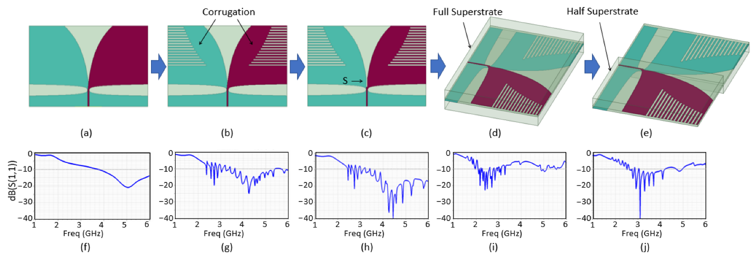
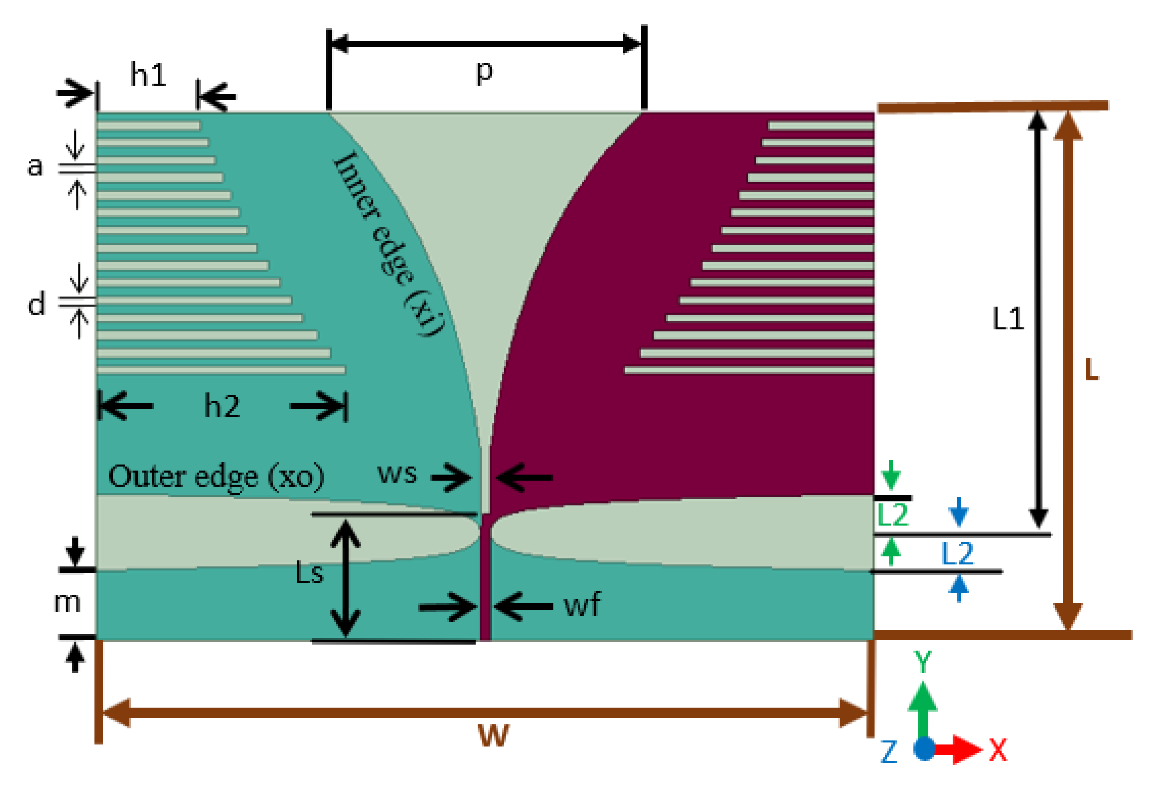
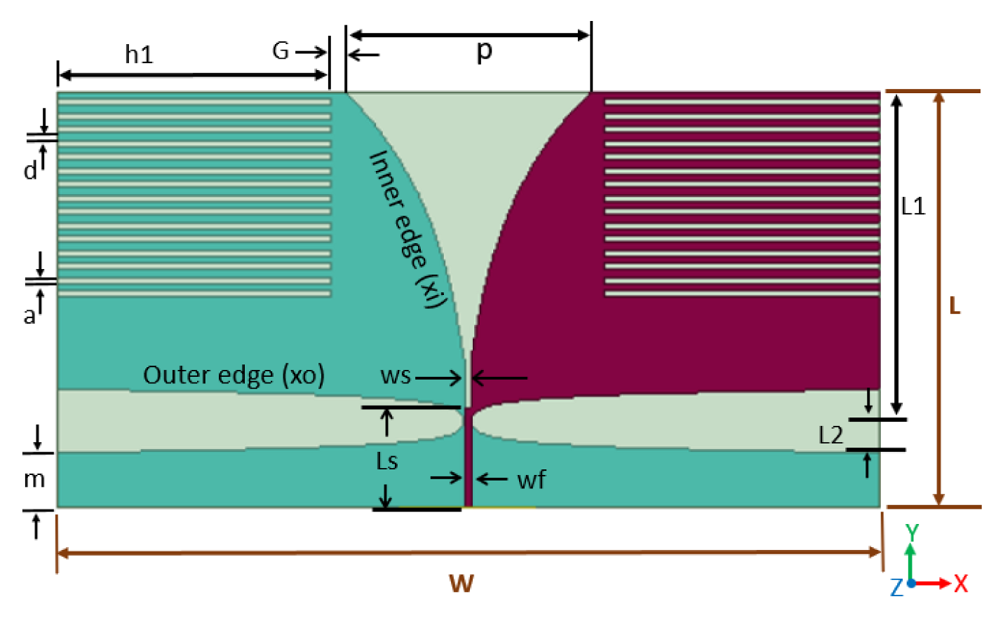
3.1. Design Evolution

The evolution stages in the design of the proposed antenna 1 are shown in Figure 1. Below, the antenna design of each of these stages is explained, and the performances of the designs are compared in terms of the reflection coefficient (S11).

3.1.1. Stage 1 (Conventional Antipodal Vivaldi Design)

Figure 1a shows the initial design for the antenna, which is formulated using the conventional antipodal Vivaldi structure [24] with dimensions (W × L × h) of 44.4 × 30.2 × 0.64 mm3. The tapered slot is designed using an exponential profile similar to that used in [34]. The conventional antipodal Vivaldi feeding structure using a 50 Ω microstrip-to-slotline transition [24] is utilized. Figure 1f shows the reflection coefficient of the initial antenna design. It is observed that the antenna starts resonating (S11 < −10 dB) from ~3.6 GHz.

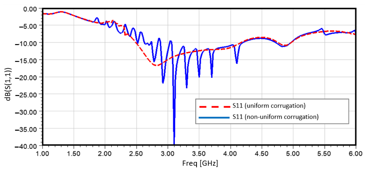
3.1.2. Stage 2 (Addition of Corrugations)

Since the initial design obtained after stage 1 does not resonate below ~3.6 GHz, symmetrical corrugations are made on both the top and bottom copper layers of the antenna, as shown in Figure 1b, in order to reduce the operating frequency of the antenna [12,16]. The number, length, and width of the slots in the corrugations are designed by performing a parametric analysis for optimizing the matching and bandwidth performance within the frequency range of interest (~1–6 GHz). Figure 1g shows the reflection coefficient of the antenna obtained after the stage 2 design. It is observed that the antenna now resonates (S11 < −10 dB) at frequencies lower than 3.6 GHz; however, there are fluctuations in the low frequencies (<3.5 GHz) due to poor matching.

3.1.3. Stage 3 (Addition of Feed Slot)

A rectangular slot ‘S’ is inserted at the beginning of the tapered slot near the feed region, as shown in Figure 1c, in order to improve the matching performance [18]. From the reflection coefficient plot of Figure 1h for the stage 3 antenna design, it is seen that the matching is improved in the high-frequency end, whereas the low-frequency end performance remains similar to that in the stage 2 design.

3.1.4. Stage 4 (Addition of Superstrates)

Two superstrates are added on both the top and bottom radiators, as shown in Figure 1d. The thickness of each of the superstrates is set to 4 h, where h is the thickness of the substrate. Parametric analysis is carried out to design the thickness in order to optimize the matching performance of the antenna. The same material as that used for the substrate (Rogers RT6010 with ɛr = 10.2) is used for the superstrates. The addition of superstrates aids in attaining low-frequency operation, as demonstrated in the S11 plot of Figure 1i. However, the matching is degraded at frequencies above ~3.3 GHz.

3.1.5. Stage 5 (Reduction of the Width of the Superstrates)

The width of the superstrates is reduced to half of that of the substrate to obtain better matching at high frequencies than the antenna of the stage 4 design. The corresponding antenna is shown in Figure 1e, and the reflection coefficient is shown in Figure 1j. It can be seen that the S11 of the antenna now provides better matching at frequencies above 3.3 GHz than the stage 4 antenna and at frequencies below 3.5 GHz than the stage 1 to stage-3 designs. Though the matching performance is degraded at frequencies below 2.5 GHz compared to the stage 4 antenna, the bandwidth is increased compared to that of the stage 4 antenna after reducing the width of the superstrates. Hence, the antenna obtained after the stage 5 design is adopted as the proposed design.
The top view of the final design of the proposed antenna 1 is shown in Figure 2. The inner and outer edge tapers of the antenna follow the exponential characteristics [34], as shown in Equations (1) and (2).
xi = ±0.5 wf ± 0.5 w1 [exp (ksy) – 1]
xo = ±0.5 wf ± 0.5 w2 [exp (kwy^sf) – 1]
Here, xi and xo are the distances of the inner and outer edges from the slot center line, respectively. The other parameters are: w1 = 1.7304 mm, w2 = 0.18 mm, kw = 2500, sf = 1, and ks = ln((wf + p + w1)/w1)/L1, where L1 = 24 mm and p = 18 mm.
The width of the microstrip-feedline is wf = 0.5 mm, which is connected to the top surface of the antenna. The ground plane is extended along the length by a factor m = 4 mm. The value for ‘m’ is designed by the parametric analysis to obtain good matching and bandwidth performance. The tapered edges of the ground plane feeding are also designed using a similar exponential profile as that in Equation (2), which extends for a length of L2 = 2.2 mm.
There are 15 slots in the corrugations of each layer. The slots in the corrugations have a width (a) and separation (d) between two consecutive slots equal to 0.5 mm. The lengths are designed to gradually increase from h1 = 6 mm near the tapered slot opening (p) to h2 = 14.27 mm near the feed region, with a rate of 1/τ, where τ = 0.94.
Additionally, a slot (S) of width ws = 0.5 mm is introduced near the feed at a distance of Ls = 7.2 mm from the port. The width (ws) and position (Ls) of the slot are designed after performing a parametric analysis to obtain better matching performance. The design of the width and the position of the slot (S) require meticulous considerations of both the matching performance and the physical realizability of the antenna. Due to the narrow width of the top copper layer near the feed region, the trace width can become very thin if the slot width (ws) is increased beyond 0.5 mm while placed at a distance of 7.2 mm or less from the port. In order to analyze the effect of increasing the slot width, the position of the slot needs to be moved further away from the port; however, increasing the ws and Ls significantly distorts the exponential profile of the tapered slot near the feed region and can hence adversely impact the performance of the antenna.
It has been shown that, for antennas with a shorter height than other major dimensions (length, width), the performance critically depends on the secondary parameters [36]. Therefore, the dimensions of the slots in the corrugation and those of the feed slot play an important role in determining the performance of the antenna.
The two half-cut superstrates cover only the copper layers on both the top and bottom radiating surfaces. The length, width, and thickness of each superstrate are L, W/2, and 4 h, respectively, where L, W, and h are the length, width, and thickness of the substrate.
Finally, no matching/coupling liquid is incorporated to aid in achieving good matching characteristics within the desired frequency range.

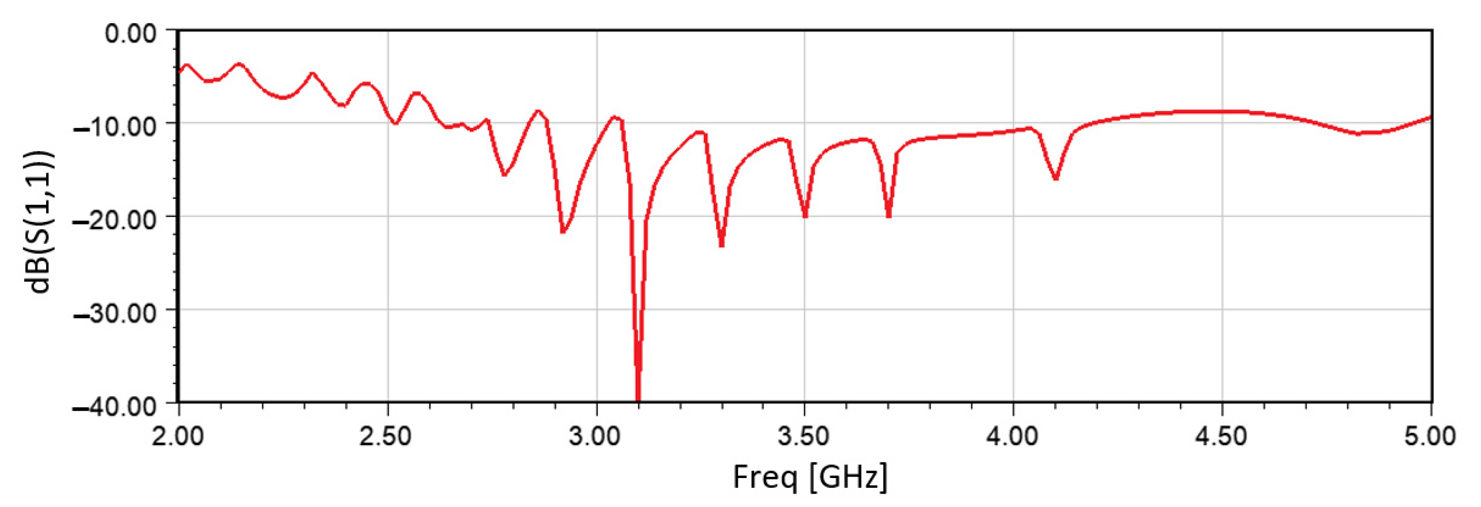
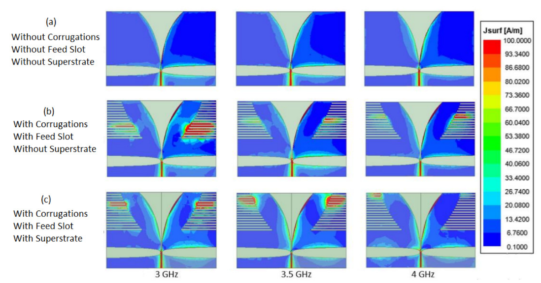
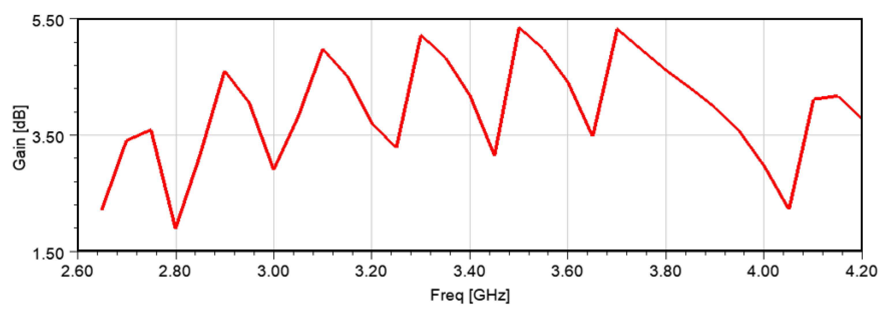
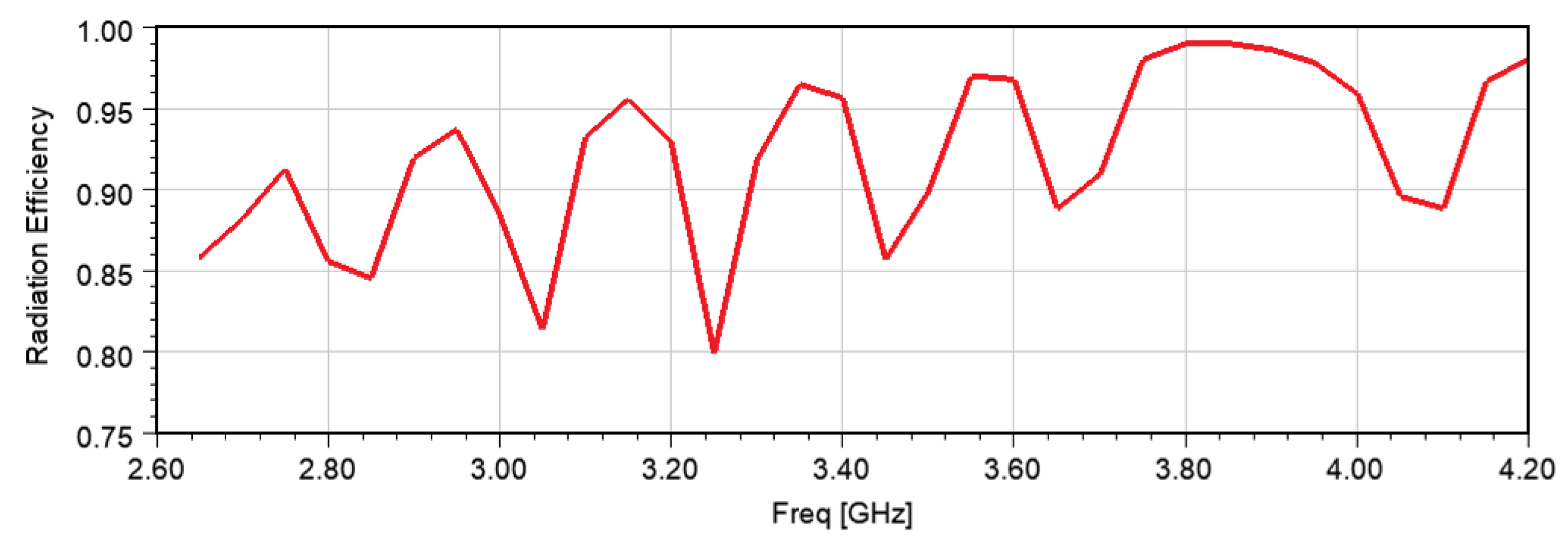
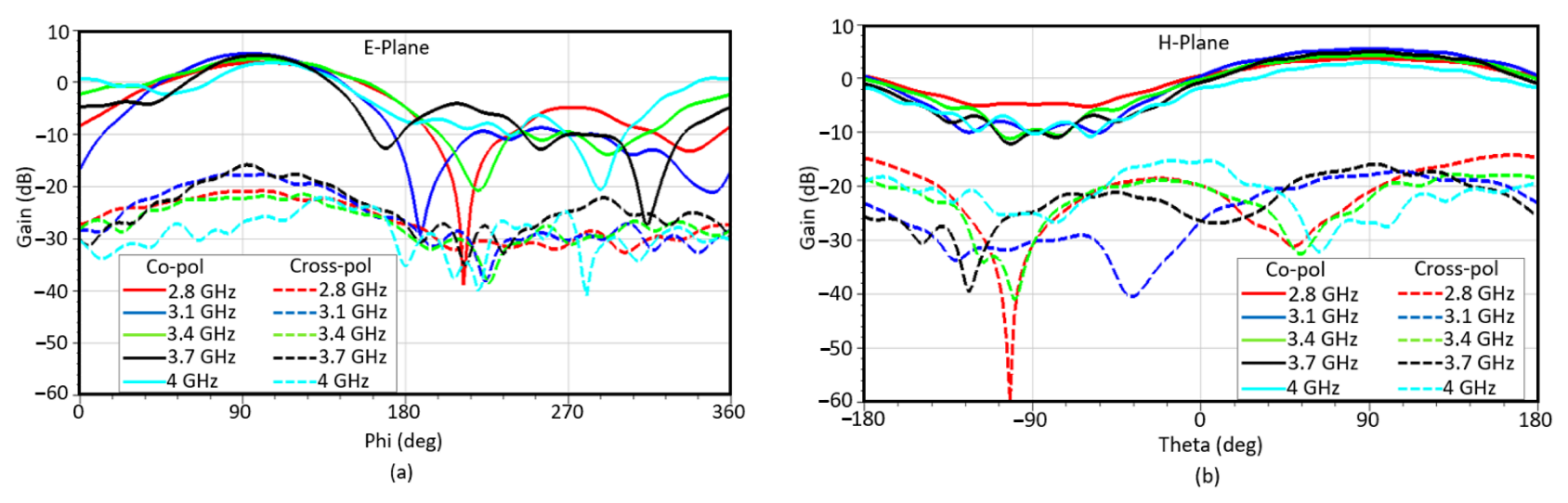
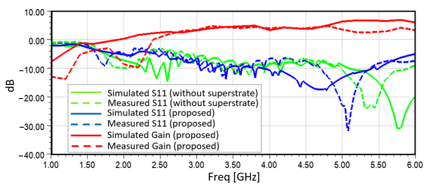
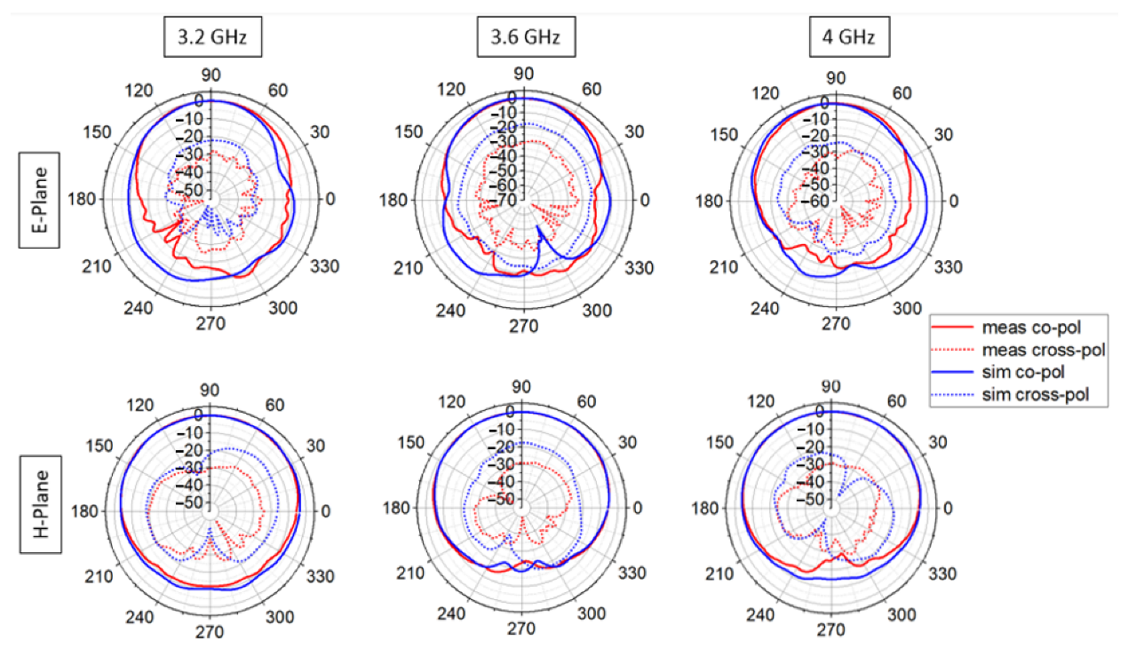
3.2. Performance Analysis

ANSOFT HFSS software is used for all the simulations in this work, having the antenna model excited with the wave-port. Figure 3 shows the reflection coefficient (S11) of the antenna within 2–5 GHz frequency range. From the reflection coefficient plot, it can be seen that S11 is less than −10 dB from ~2.65–4.2 GHz, entailing a bandwidth of ~1.55 GHz. However, the S11 is slightly higher than −10 dB for a few frequencies near ~2.85 GHz and 3.05 GHz.
The effect of adding the corrugation, feed slot, and superstrates is analyzed on the surface current distribution of the antenna. In Figure 4, the surface current distribution of the antenna is shown at 3 GHz, 3.5 GHz, and 4 GHz. From Figure 4a, it can be seen that, before adding the corrugations, feed slot, and superstrates, the current is very low along the tapered slot edges at 3 GHz, as the antenna does not resonate at this frequency. After the inclusion of the corrugations and the feed slot (Figure 4b), the current is significantly increased on both the top and bottom layers of the antenna at 3 GHz, as the lower operating frequency is reduced and, hence, the antenna now resonates at 3 GHz. However, compared to the current distributions at 3.5 GHz and 4 GHz, the current distribution at 3 GHz of Figure 4b shows an asymmetry on the top and bottom layers, which causes a deviation of the antenna main beam from the end-fire direction. From Figure 4c, it can be seen that the asymmetry is removed at 3 GHz after the addition of the superstrates on both layers. Moreover, the magnitude of current is increased along the tapered slot edge at these three frequencies after the addition of the superstrates. An analysis of the effect of placing a head model in front of the antenna on the surface current distribution of the antenna is expected to be presented in a follow-up paper.
Figure 5 and Figure 6 show the peak realized gain and radiation efficiency of the proposed antenna 1, respectively, within the resonant frequency band. The peak realized gain fluctuates between the maximum and minimum of ~5.2 dB and ~1.9 dB, respectively. The radiation efficiency of the antenna is above 80% for the entire resonant bandwidth.
Figure 7a,b show the co- and cross-polarized radiation patterns of the proposed antenna 1 in the E- and H-plane at a few frequencies within the bandwidth. It can be seen that the peak co-polarized gain occurs toward the end-fire direction (φ = 90°, θ = 90°) for all these frequencies, except at 4 GHz, where the E-plane peak radiation is slightly tilted toward φ = 110° while having a high sidelobe gain (~0 dB) toward φ = 0°. However, the comparatively large sidelobe level can be accepted, as it is below the level of the peak gain at 4 GHz. The cross-polarization level is less than −14 dB for both the E- and H-plane at all these frequencies.

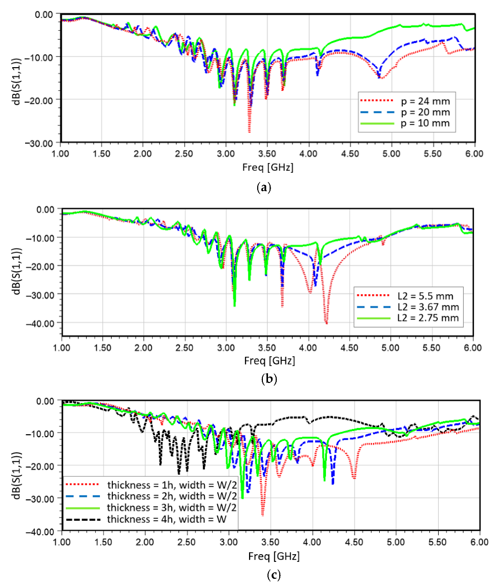
3.3. Parametric Analysis

Extensive parametric analysis is carried out to investigate the effect of different antenna design parameters on the performance improvement of the antenna in terms of the bandwidth and matching performance within the intended range of frequencies (~1–6 GHz). The reflection coefficients obtained by varying some of the parameters, e.g., the tapered slot opening (p), the feed transition length (L2), and the width and thickness of the superstrate, are shown in Figure 8. From Figure 8a, it can be seen that, as the tapered slot opening (p, as denoted in Figure 2) increases, the antenna provides better matching, especially at higher frequencies, and, hence, the bandwidth is increased toward the higher frequency end. From Figure 8b, it can be seen that, as the feed transition length (L2, as denoted in Figure 2) increases, the matching performance improves at higher frequencies; however, the bandwidth remains almost the same. From Figure 8c, it can be seen that, as the thickness of the superstrate increases, while keeping the width at half of the substrate width (W/2), the bandwidth is reduced at the high-frequency end, whereas, by increasing the width of the superstrate to be equal to the substrate width (W), resonances are obtained at lower frequencies. However, the bandwidth is smaller than that obtained with a width half that of the superstrates.

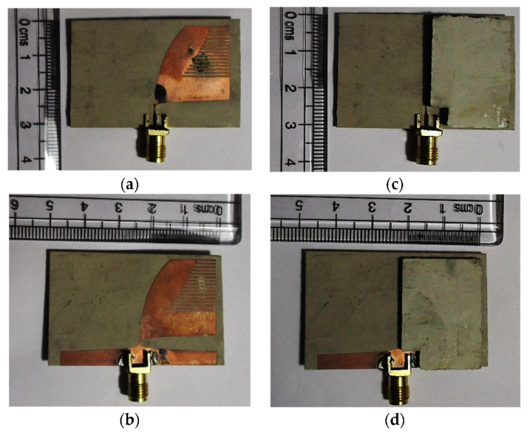
3.4. Fabrication and Measurement

A prototype of the proposed antenna 1 is fabricated using the chemical etching method. Figure 9 shows the fabricated prototype of antenna 1 before and after attaching the supertrate. Rogers RT/duroid 6010.2LM laminate with a thickness of 0.025 inches is used for the substrate, while the superstrates are built using unclad Rogers RO 3010 laminates with a thickness of 0.1 inch. The refelction coefficient of the prototype antenna is measured using N5230A PNA-L. The radiation pattern is measured inside an anechoic chamber. The gain of the prototype antenna is measured using the absolute gain measurement technique.
Figure 10 shows the measured reflection coefficient and gain of the prototype antenna. The corresponding simulation results are also presented for comparison. However, the simulation results are obtained after incorporating the fabrication inaccuracies into the antenna model. The misalignment between the top and bottom layers is modeled as a 1 mm offset along the width and a 0.5 mm offset along the length of the antenna. An airgap with a uniform thickness of 0.2 mm is inserted between the substrate and superstrate. A 5 × 5 mm2 portion is cut from each of the superstrates to accommodate the SMA connector. However, some of the fabrication issues were not modeled in the simulation, such as the slight breaking of the corrugations, which was repaired using soldering iron; the actual thickness of the airgap, which could not be inferred; etc. While keeping these facts in mind, it can be observed that the measured reflection coefficient and gain of the prototype antenna show a reasonable agreement with the simulation results, except for a slight shift in the resonant frequency of ~0.5 GHz after 4.5 GHz.
In Figure 11, the measured co- and cross-polarized radiation patterns (in terms of gain in dB) of the fabricated prototype of the proposed antenna 1 are compared with the simulation results at some frequencies within the resonant frequency band. The antenna radiates toward the end-fire direction at all these frequencies. The co-polarized radiation pattern matches quite closely with that of the simulation results toward the end-fire direction. Both the measured and simulated co-polarized radiation level toward the backward direction are significantly lower than the peak radiation level. Though the measured cross-polarized radiation pattern is different than that of the simulation results, the radiation level is lower than ~−15 dB at all these frequencies. Hence, the cross-polarized radiation pattern does not bear a significant impact on the antenna radiation performance.

4. Proposed Antenna 2

A variation of the proposed antenna 1 is designed by increasing the width of the antenna in order to obtain a lower frequency of operation within the intended range of frequencies (1–6 GHz). The same material (Rogers RT6010 with a dielectric constant ɛr = 10.2) with a thickness h = 0.64 mm is used as the substrate. The proposed antenna 2 has an overall length and width of 30.32 mm and 60 mm, respectively. Figure 12 shows the top view of the proposed antenna 2. The key design features of this antenna are discussed below.

4.1. Design Features

The inner and outer edges (xi and xo) of the antenna are designed using the exponentially tapered profiles mentioned in Equations (1) and (2), respectively [34]. The length, L1, and tapered slot opening, p, are kept at 24 mm and 18 mm, respectively, like those in the proposed antenna 1. This results in the same rate (ks) of the exponential profile in the inner edge as that in the antenna 1. The feed transition region in the ground plane is designed using the tapered profile used in the proposed antenna 1. However, the length of the feed transition (L2) in the ground plane is increased to 2.32 mm in order to keep the rate of the taper (kw = 2500) the same as that in the proposed antenna 1 while increasing the width (W) of the antenna. The width of the feed line on the top layer is wf = 0.5 mm, and the length of the feed extension is m = 4 mm, which are similar to the values used in antenna 1.
A similar slot of width ws = 0.5 mm is inserted at a distance of Ls = 7.32 mm from the port. As explained in Section 3.1, the width and position of the slot have a critical impact on the antenna performance at the higher end of the operating frequency range. Again, the placement of the feed slot requires the consideration of both the performance and physical realizability of the antenna. However, unlike the design of antenna 1, parametric analysis is not carried out to investigate the impact of the width and the position of the feed slot on the performance of the antenna 2. Rather, a similar width and distance as those used in antenna 1 are utilized for designing the feed slot for antenna 2.
Corrugations are inserted on both the top and bottom layers of the antenna. There are 15 slots in the corrugations of each layer. The slots in the corrugations have an equal length h1 = 20 mm, which is different than that in the proposed antenna 1, where a gradually increasing length is used for the slots in the corrugations. Again, the width, a, and separation, d, between the two adjacent slots in the corrugations are equal to 0.5 mm each. The gap between the corrugation edge and the final opening of the inner edge is G = 1 mm. The length, h1, and, hence, the gap, G, are designed by performing parametric analysis to optimize the bandwidth and matching performance of the antenna within the intended frequency range (1–6 GHz).
Two superstrates are added on both the top and bottom layers of the antenna, like those in the proposed antenna 1 (as shown in Figure 1e). Each superstrate is designed using the same material as that used for the substrate (Rogers RT6010 with a dielectric constant, ɛr = 10.2), with a length = L, width = W/2, and thickness = 4 h, where L, W, and h are the length, width, and thickness of the substrate, respectively. As mentioned in Section 3.1, since the superstrates have half the width of the substrate, the superstrates cover only the copper layers on both the top and bottom layers of the antenna.

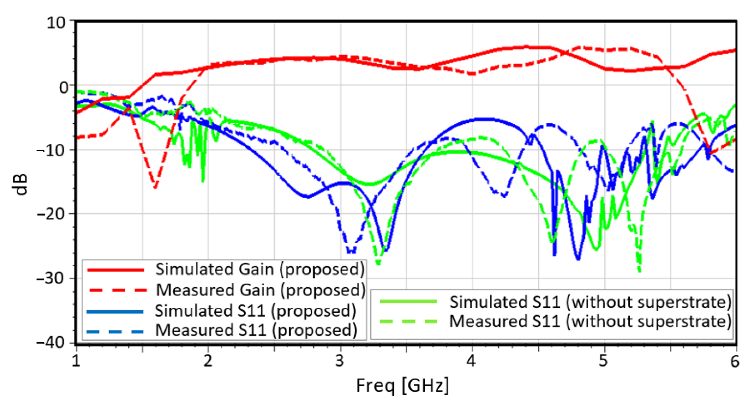
4.2. Performance Analysis

The proposed antenna 2 is simulated using ANSOFT HFSS software. The antenna model is excited with a wave-port.
Figure 13 shows the reflection coefficient (S11) of the proposed antenna 2 within the 1–6 GHz frequency range. From the reflection coefficient plot, it can be seen that the antenna resonates (S11 < −10 dB) from ~1.9–5.4 GHz, entailing a bandwidth of ~3.5 GHz. However, the S11 is very close to −10 dB for frequencies within the range of 3.6–4.6 GHz.
Figure 14 and Figure 15 show the peak realized gain and radiation efficiency of the proposed antenna 2, respectively, within the resonant frequency band. The peak realized gain fluctuates between the maximum and minimum of ~5.5 dB and ~1.5 dB, respectively. The radiation efficiency of the antenna is above 90% for the entire resonant bandwidth.
Figure 16a,b show the co- and cross-polarized radiation patterns of the proposed antenna 2 in the E- and H-plane for a few frequencies within the bandwidth. It can be seen that the peak co-polarized gain occurs toward the end-fire direction (φ = 90°, θ = 90°) for all these frequencies, except at 4 GHz, where the E-plane peak radiation is slightly tilted toward φ = 80°. The antenna shows low sidelobe levels (<0 dB) at all these frequencies, whereas the cross-polarization level is less than −15 dB for both the E- and H-planes at all these frequencies.

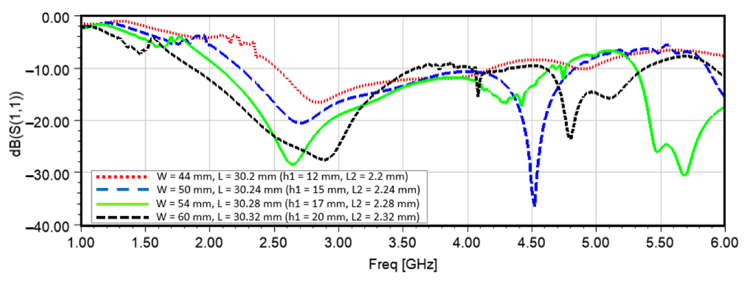
4.3. Parametric Analysis

As mentioned earlier in this section, the proposed antenna 2 is designed with an increased width in order to achieve low-frequency operation. The effect of the width of the antenna on the reflection coefficient is investigated by performing a parametric analysis to obtain a higher bandwidth, especially toward the low-frequency end.
Figure 17 shows the reflection coefficient of the proposed antenna 2 for different widths. The feed transition length, L2 is varied with the variation of the width of the antenna in order to keep the exponential taper rate of the outer edge (as shown in Figure 12) constant at kw = 2500. This results in a slight increase in the overall length, L, of the antenna. The length, h1, of the slots in the corrugations (as shown in Figure 12) is also adjusted to keep the gap, G, between the corrugation edge and final tapered slot edge (as shown in Figure 12) constant at G = 1 mm. The adjusted values of the parameters L2, L, and h1 with the corresponding widths are listed in Figure 17. It is observed that, as the width of the antenna is increased, the low resonant frequency of the antenna reduces; hence, the bandwidth extends toward the low-frequency end.

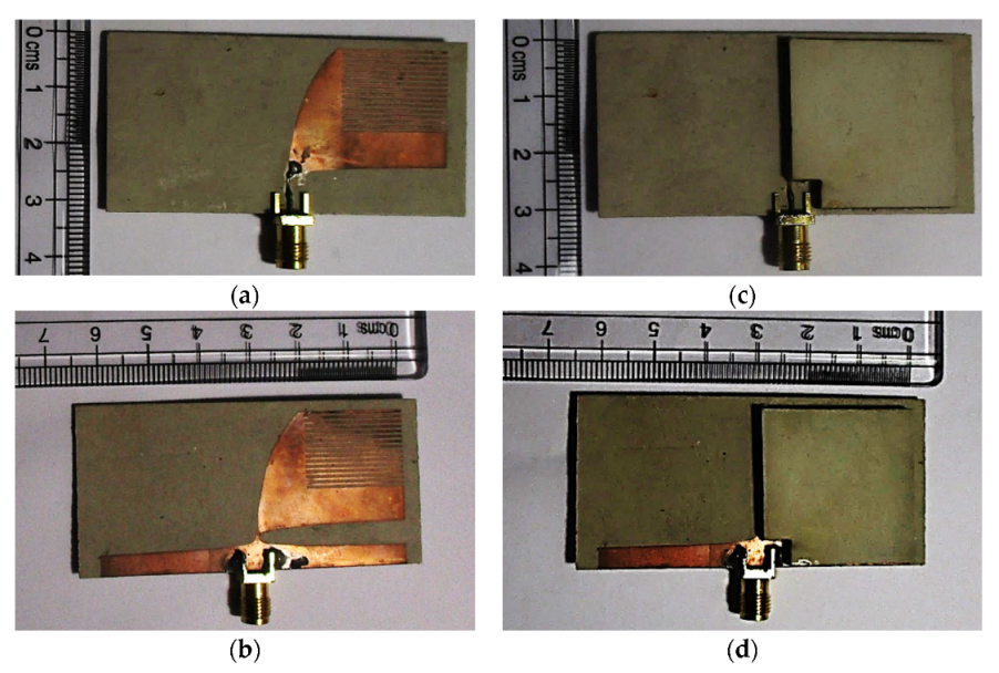
4.4. Fabrication and Measurement

A prototype of the proposed antenna 2 is fabricated using the chemical etching method. Figure 18 shows the fabricated prototype of antenna 2 before and after attaching the superstrate. The fabrication is done on the same board (Rogers RT/duroid 6010.2LM) as that used for antenna 1, while Rogers RO 3010 laminates with a thickness of 0.1 inches are used as the superstrates. The refelction coefficient, radiation pattern, and gain of the prototype antenna are measured using the same equipment and techniques as those mentioned in Section 3.4 for antenna 1.
Figure 19 shows the measured reflection coefficient and gain of the prototype antenna. The corresponding simulation results are also presented for comparison. However, the simulation results are obtained after incorporating the fabrication inaccuracies into the antenna model. The misalignment between the top and bottom layers is modeled in the same way as that done for the antenna 1. An airgap with a uniform thickness of 0.1 mm is inserted between the substrate and superstrate. A 5 × 5 mm2 portion is cut from each of the superstrates to accommodate the SMA connector. It can be observed that the reflection coefficients and gain of the prototype antenna show a reasonable agreement with the simulation results, except for a slight shift in the resonant frequencies of ~0.5 GHz.
In Figure 20, the measured co- and cross-polarized radiation pattern (in terms of gain in dB) of the fabricated prototype of the proposed antenna 2 is compared with the simulation results at some frequencies within the resonant frequency band. The antenna radiates toward the end-fire direction at all these frequencies. The co-polarized radiation pattern matches quite closely with that of the simulation results toward the end-fire direction. Both the measured and simulated co-polarized radiation level toward the backward direction are significantly lower than the peak radiation level. Though the measured cross-polarized radiation pattern is different than that of the simulation results, the radiation level is lower than ~−15 dB at all these frequencies. Hence, the cross-polarized radiation pattern does not bear a significant impact on the antenna radiation performance.

5. Comparison

The proposed antennas vary in terms of the type of corrugations. The slots in the corrugation of the proposed antenna 1 have a gradually increasing length, i.e., a non-uniform length, while those of the proposed antenna 2 have a uniform length. The performances of the antennas with different types of corrugations are compared by scaling down the dimensions of the proposed antenna 2 to be equal to those of the proposed antenna 1 in order to ensure an equivalence in the comparison. The new parameters of the proposed antenna 2 are W = 44.4 mm, L = 30.2 mm, L1 = 24 mm, L2 = 2.2 mm, m = 4 mm, p = 18 mm, G = 1 mm, and h1 = 12.2 mm (the parameters are defined as shown in Figure 12). In Figure 21, the reflection coefficient is plotted for the antennas with uniform and non-uniform corrugations. It can be seen that the design with non-uniform corrugations, where the slots in the corrugation have gradually increasing lengths, provides a better matching performance at some frequencies within the resonant frequency band.
In Table 1, the proposed antennas are compared with some of the other state-of-the-art Vivaldi antennas used in the frequency range of ~1–6 GHz. It is noticeable that the antennas that are designed using substrates with a low dielectric constant (ϵr < 6) have larger dimensions than those with a high dielectric constant (e.g., ϵr = 10.2). The antenna in [23] demonstrated low-frequency operation (1.8–10.8 GHz) with smaller dimensions than the antennas proposed in this work, without reporting any use of matching liquid. All the other antennas that use a substrate with a high dielectric constant (ϵr = 10.2) require either matching liquid or larger dimensions than those of the proposed antennas in order to achive low-frequency operation.

6. Conclusions

In this paper, two miniaturized antipodal Vivaldi antennas have been proposed for applications in the wideband microwave imaging of the head. Several miniaturization techniques have been adopted for reducing the size of the antennas while maintaining the desired matching and bandwidth performance in the low microwave frequency range. A major consideration in this design was to eliminate the need of immersing the antennas into any matching/coupling liquid while being used for the microwave imaging of the head. This goal has been achieved, in addition to achieving a miniaturized wideband Vivaldi antenna. The simulation results of the proposed antennas demonstrate wideband operation with a resonant (S11 < −10 dB) frequency range from ~2.65–4.2 GHz for the antenna 1 and from ~1.9–5.4 GHz for the antenna 2, entailing a fractional bandwidth of 45.26% and 95.9%, respectively, within 1–6 GHz. The peak realized gain of the proposed antennas fluctuate within ~1.9–5.2 dB and ~1.5–5.5 dB, respectively, while the antennas have a radiation efficiency above 80% within the resonant bandwidth. Both of the antennas offer end-fire radiation at different frequencies within the respective resonant bandwidths. The prototype of each antenna has been fabricated, and the reflection coefficient, gain, and far field radiation patterns have been measured, which show a reasonable agreement with the simulation results. Finally, the proposed antennas have been compared with several state-of-the-art Vivaldi antennas, and this comparison demonstrates the feasibility of the antennas in obtaining the desired performance in the intended frequency range with miniaturized dimensions.

Author Contributions

Conceptualization, P.W.; methodology, P.W.; software, F.P.; validation, F.P. and P.W.; formal analysis, F.P. and P.W.; investigation, F.P. and P.W.; resources, F.P. and P.W.; data curation, F.P.; writing—original draft preparation, F.P.; writing—review and editing, P.W.; visualization, F.P. and P.W.; supervision, P.W.; project administration, P.W. All authors have read and agreed to the published version of the manuscript.

Funding

This research received no external funding.

Acknowledgments

The authors would like to thank Junyi Huang and Yuchen Cao for helping with the antenna fabrication and measurement.

Conflicts of Interest

The authors declare no conflict of interest.

References

  1. Zu, H.; Wu, B.; Yang, P.; Li, W.; Liu, J. Wideband and High-Gain Wearable Antenna Array with Specific Absorption Rate Suppression. Electronics 2021, 10, 2056. [Google Scholar] [CrossRef]
  2. Al-Gburi, A.J.A.; Ibrahim, I.M.; Zakaria, Z.; Abdulhameed, M.K.; Saeidi, T. Enhancing gain for UWB antennas using FSS: A systematic review. Mathematics 2021, 9, 3301. [Google Scholar] [CrossRef]
  3. Hasan, M.; Faruque, M.R.I.; Islam, M.T.I. Dual band metamaterial antenna for LTE/bluetooth/WiMAX system. Sci. Rep. 2018, 8, 1240. [Google Scholar] [CrossRef] [PubMed] [Green Version]
  4. Hasan, M.; Faruque, M.R.I.; Islam, M.T. Thin-layer dielectric and left-handed metamaterial stacked compact triband antenna for 2 GHz to 4 GHz wireless networks. J. Electron. Mater. 2019, 48, 3979–3990. [Google Scholar] [CrossRef]
  5. Hasan, M.M.; Rahman, M.; Faruque, M.R.I.; Islam, M.T.; Khandaker, M.U. Electrically compact SRR-loaded metamaterial inspired quad band antenna for bluetooth/WiFi/WLAN/WiMAX system. Electronics 2019, 8, 790. [Google Scholar] [CrossRef] [Green Version]
  6. Ahmed, A.; Kumari, V.; Sheoran, G. Metamaterial surface and modified Vivaldi antenna to tune gain of microwave imaging instrument. Meas. Sci. Technol. 2020, 32, 035901. [Google Scholar] [CrossRef]
  7. Tan, G.-N.; Yang, X.-X.; Lu, Z.-L.; Jiang, X.-S. Metamaterial loaded vivaldi antenna with high gain and equal beamwidths at KA band. Microw. Opt. Technol. Lett. 2016, 58, 2337–2341. [Google Scholar] [CrossRef]
  8. Bhaskar, M.; Johari, E.; Akhter, Z.; Akhtar, M.J. Gain enhancement of the Vivaldi antenna with band notch characteristics using zero-index metamaterial. Microw. Opt. Technol. Lett. 2015, 58, 233–238. [Google Scholar] [CrossRef]
  9. Sun, M.; Chen, Z.N.; Qing, X. Gain enhancement of antipodal tapered slot antenna using zero-index metamaterial. In Proceedings of the 2012 IEEE Asia-Pacific Conference on Antennas and Propagation, Singapore, 27–29 August 2012. [Google Scholar]
  10. Joula, M.; Rafiei, V.; Karamzadeh, S. High gain UWB bow-tie antenna design for ground penetrating radar application. Microw. Opt. Technol. Lett. 2018, 60, 2425–2429. [Google Scholar]
  11. Chi, P.-L.; Waterhouse, R.; Itoh, T. Antenna miniaturization using slow wave enhancement factor from loaded transmission line models. IEEE Trans. Antennas Propag. 2010, 59, 48–57. [Google Scholar] [CrossRef]
  12. Abbosh, A. Miniaturization of planar ultrawideband antenna via corrugation. IEEE Antennas Wirel. Propag. Lett. 2008, 7, 685–688. [Google Scholar] [CrossRef]
  13. Qing, X.; Chen, Z.N.; Chia, M.Y.W. Dual elliptically tapered antipodal slot antenna loaded by curved terminations for ultrawideband applications. Radio Sci. 2006, 41, 1–14. [Google Scholar] [CrossRef]
  14. Kildal, P.-S. Artificially soft and hard surfaces in electromagnetics. IEEE Trans. Antennas Propag. 1990, 38, 1537–1544. [Google Scholar] [CrossRef]
  15. Bai, J.; Shi, S.; Prather, D.W. Modified compact antipodal Vivaldi antenna for 4–50-GHz UWB application. IEEE Trans. Microw. Theory Tech. 2011, 59, 1051–1057. [Google Scholar] [CrossRef]
  16. Wang, Z.; Zhang, H. Improvements in a high gain UWB antenna with corrugated edges. Prog. Electromagn. Res. 2009, 6, 159–166. [Google Scholar] [CrossRef] [Green Version]
  17. Mohammed, B.J.; Abbosh, A.M.; Bialkowski, M.E. Design of tapered slot antenna operating in coupling liquid for ultrawideband microwave imaging systems. In Proceedings of the 2011 IEEE International Symposium on Antennas and Propagation (APSURSI), Spokane, WA, USA, 3–8 July 2011. [Google Scholar]
  18. Beada’a, J.M.; Abbosh, A.M.; Ireland, D.; Bialkowski, M.E. Wideband antenna for microwave imaging of brain. In Proceedings of the 2011 Seventh International Conference on Intelligent Sensors, Sensor Networks and Information Processing (ISSNIP), Adelaide, SA, Australia, 6–9 December 2011. [Google Scholar]
  19. Bourqui, J.; Okoniewski, M.; Fear, E.C. Balanced antipodal Vivaldi antenna with dielectric director for near-field microwave imaging. IEEE Trans. Antennas Propag. 2010, 58, 2318–2326. [Google Scholar] [CrossRef]
  20. Lazaro, A.; Villarino, R.; Girbau, D. Design of tapered slot Vivaldi antenna for UWB breast cancer detection. Microw. Opt. Technol. Lett. 2011, 53, 639–643. [Google Scholar] [CrossRef]
  21. Gibson, P. The vivaldi aerial. In Proceedings of the 1979 9th European Microwave Conference, Brighton, UK, 17–20 September 1979. [Google Scholar]
  22. Wang, S.; Chen, X.; Parini, C. Analysis of ultra wideband antipodal Vivaldi antenna design. In Proceedings of the 2007 Loughborough Antennas and Propagation Conference, Loughborough, UK, 2–3 April 2007. [Google Scholar]
  23. Abbosh, A.M. Miniaturized microstrip-fed tapered-slot antenna with ultrawideband performance. IEEE Antennas Wirel. Propag. Lett. 2009, 8, 690–692. [Google Scholar] [CrossRef] [Green Version]
  24. Gazit, E. Improved design of the Vivaldi antenna. In Proceedings of the IEE Proceedings H (Microwaves, Antennas and Propagation). IET Digit. Libr. 1988, 135, 89–92. [Google Scholar]
  25. Fallahpour, M.; Zoughi, R. Antenna miniaturization techniques: A review of topology-and material-based methods. IEEE Antennas Propag. Mag. 2017, 60, 38–50. [Google Scholar] [CrossRef]
  26. Kula, J.S.; Psychoudakis, D.; Liao, W.-J.; Chen, C.-C.; Volakis, J.L.; Halloran, J.W. Patch-antenna miniaturization using recently available ceramic substrates. IEEE Antennas Propag. Mag. 2006, 48, 13–20. [Google Scholar] [CrossRef]
  27. Lee, B.; Harackiewicz, F. Miniature microstrip antenna with a partially filled high-permittivity substrate. IEEE Trans. Antennas Propag. 2002, 50, 1160–1162. [Google Scholar]
  28. Milligan, T.A. Modern Antenna Design; John Wiley & Sons: Hoboken, NJ, USA, 2005. [Google Scholar]
  29. Maci, S.; Leoncini, M.; Neto, A.; Tiberio, R.; Toccafondi, A. Diffraction at artificially soft and hard edges by using incremental theory of diffraction. In Proceedings of the IEEE Antennas and Propagation Society International Symposium and URSI National Radio Science Meeting, Seattle, WA, USA, 20–24 June 1994. [Google Scholar]
  30. Fei, P.; Jiao, Y.-C.; Hu, W.; Zhang, F.-S. A miniaturized antipodal Vivaldi antenna with improved radiation characteristics. IEEE Antennas Wirel. Propag. Lett. 2011, 10, 127–130. [Google Scholar]
  31. Sugawara, S.; Maita, Y.; Adachi, K.; Mori, K.; Mizuno, K. A mm-wave tapered slot antenna with improved radiation pattern. In Proceedings of the 1997 IEEE MTT-S International Microwave Symposium Digest, Denver, CO, USA, 8–13 June 1997. [Google Scholar]
  32. Sugawara, S.; Maita, Y.; Adachi, K.; Mori, K.; Mizuno, K. Characteristics of a mm-wave tapered slot antenna with corrugated edges. In Proceedings of the 1998 IEEE MTT-S International Microwave Symposium Digest (Cat. No. 98CH36192), Baltimore, MD, USA, 7–12 June 1998. [Google Scholar]
  33. Nassar, I.T.; Weller, T.M. A novel method for improving antipodal Vivaldi antenna performance. IEEE Trans. Antennas Propag. 2015, 63, 3321–3324. [Google Scholar] [CrossRef]
  34. Wang, P.; Zhang, H.; Wen, G.; Sun, Y. Design of modified 6–18 GHz balanced antipodal Vivaldi antenna. Prog. Electromagn. Res. C 2012, 25, 271–285. [Google Scholar] [CrossRef] [Green Version]
  35. Parveen, F.; Wahid, P. Microwave Head Imaging System for Detection of Blood Clots inside the Brain. In Proceedings of the 2021 IEEE International Symposium on Antennas and Propagation and USNC-URSI Radio Science Meeting (APS/URSI), Singapore, 4–10 December 2021. [Google Scholar]
  36. Gupta, S.; Kshirsagar, P.; Mukherjee, B. A Low-Profile Multilayer Cylindrical Segment Fractal Dielectric Resonator Antenna: Usage for wideband applications. IEEE Antennas Propag. Mag. 2019, 61, 55–63. [Google Scholar] [CrossRef]
  37. Chen, L.; Wang, C.; Li, H.; Lan, S. A miniaturized antipodal vivaldi antenna for microwave imaging. In Proceedings of the 2017 International Symposium on Antennas and Propagation (ISAP), Phuket, Thailand, 30 October–2 November 2017. [Google Scholar]
  38. Aldhaeebi, M.A.; Elshafiey, I. Development of UWB Vivaldi antenna for microwave imaging. In Proceedings of the 2013 Saudi International Electronics, Communications and Photonics Conference, Riyadh, Saudi Arabia, 27–30 April 2013. [Google Scholar]
  39. Salleh, A.; Yang, C.C.; Singh, M.S.J.; Islam, M.T. Development of antipodal Vivaldi antenna for microwave brain stroke imaging system. Int. J. Eng. Technol. 2019, 8, 162–168. [Google Scholar]
  40. Chen, L.; Zhong, H.; Zhang, S.; Xia, L.; Zong, H.; Lan, S.A. Resistance Loaded Vivaldi Antenna for Microwave Imaging. In Proceedings of the 2018 International Symposium on Antennas and Propagation (ISAP), Busan, Korea, 23–26 October 2018. [Google Scholar]
  41. Dey, U.; Singhal, A. Design of antipodal Vivaldi antenna in matching medium for microwave medical imaging. Int. J. Eng. Res. Technol. (IJERT) 2014, 3, 1236–1239. [Google Scholar]
  42. Mohammed, B.; Abbosh, A.; Ireland, D. Directive wideband antenna for microwave imaging system for brain stroke detection. In Proceedings of the 2012 Asia Pacific Microwave Conference Proceedings, Kaohsiung, Taiwan, 4–7 December 2012. [Google Scholar]
  43. Wang, M.; Crocco, L.; Cavagnaro, M. Antipodal Vivaldi Antenna with Ceramic Cone Lens for Biomedical Microwave Imaging Systems. In Proceedings of the 2021 15th European Conference on Antennas and Propagation (EuCAP), Dusseldorf, Germany, 22–26 March 2021. [Google Scholar]
Figure 1. (ae) Design evolution of the proposed antenna 1: (a) conventional antipodal Vivaldi design, (b) addition of corrugations, (c) addition of feed slot (S), (d) addition of superstrates, (e) reduction of the width of the superstrates, (fj) reflection coefficient (S11) of the antenna after each stage of the design.
Electronics 11 02258 g001
Figure 2. Proposed antenna 1 (top view). Parameters: L = 30.2 mm, W = 44.4 mm, a = d = 0.5 mm, h1 = 6 mm, h2 = 14.27 mm, L1 = 24 mm, L2 = 2.2 mm, p = 18 mm, wf = 0.5 mm, m = 4 mm, ws = 0.5 mm, Ls = 7.2 mm (Reprinted with permission from Ref. [35], 2021, IEEE).
Electronics 11 02258 g002
Figure 3. Reflection coefficient (S11) of the proposed antenna 1.
Electronics 11 02258 g003
Figure 4. Surface current distribution on the proposed antenna 1 at 3 GHz, 3.5 GHz, and 4 GHz—(a) without corrugations, feed slot, and superstrates; (b) with corrugations and feed slot and without superstrates; and (c) with corrugations, feed slot, and superstrates.
Electronics 11 02258 g004
Figure 5. Peak realized gain of the proposed antenna 1.
Electronics 11 02258 g005
Figure 6. Radiation efficiency of the proposed antenna 1.
Electronics 11 02258 g006
Figure 7. Co- and cross-polarized radiation patterns of the proposed antenna 1 in the (a) E (XY)-plane and (b) H (YZ)-plane.
Electronics 11 02258 g007
Figure 8. Reflection coefficients of the proposed antenna 1 for different values of (a) the tapered slot opening, (b) the feed transition length, and (c) the width and thickness of the superstrate.
Electronics 11 02258 g008
Figure 9. Fabricated prototype of the proposed antenna 1: (a) top layer without the superstrate, (b) bottom layer without the superstrate, (c) top layer with the superstrate, (d) bottom layer with the superstrate.
Electronics 11 02258 g009
Figure 10. Reflection coefficient and gain of the fabricated prototype of the proposed antenna 1.
Electronics 11 02258 g010
Figure 11. Simulated and measured radiation patterns (gain in dB) of the fabricated prototype of the proposed antenna 1.
Electronics 11 02258 g011
Figure 12. Proposed antenna 2 (top view). Parameters: L = 30.32 mm, W = 60 mm, a = d = 0.5 mm, h1 = 20 mm, L1 = 24 mm, L2 = 2.32 mm, p = 18 mm, wf = 0.5 mm, m = 4 mm, ws = 0.5 mm, Ls = 7.32 mm.
Electronics 11 02258 g012
Figure 13. Reflection coefficient (S11) of the proposed antenna 2.
Electronics 11 02258 g013
Figure 14. Peak realized gain of the proposed antenna 2.
Electronics 11 02258 g014
Figure 15. Radiation efficiency of the proposed antenna 2.
Electronics 11 02258 g015
Figure 16. Co- and cross-polarized radiation patterns of the proposed antenna 2 in the (a) E (XY)-plane and (b) H (YZ)-plane.
Electronics 11 02258 g016
Figure 17. Effect of varying the width on the reflection coefficient of the proposed antenna 2.
Electronics 11 02258 g017
Figure 18. Fabricated prototype of the proposed antenna 2: (a) top layer without the superstrate, (b) bottom layer without the superstrate, (c) top layer with the superstrate, (d) bottom layer with the superstrate.
Electronics 11 02258 g018
Figure 19. Reflection coefficient and gain of the fabricated prototype of the proposed antenna 2.
Electronics 11 02258 g019
Figure 20. Simulated and measured radiation patterns (gain in dB) of the fabricated prototype of the proposed antenna 2.
Electronics 11 02258 g020
Figure 21. Effect of the type of corrugations on the reflection coefficient of the antenna.
Electronics 11 02258 g021
Table 1. Comparison of the proposed antennas with state-of-the-art Vivaldi antennas.
[Reference] Substrate (ϵr)Dimension (mm3)Operating Frequency
(GHz)
Matching Liquid?
[37] FR4 (4.3)100 × 100 × 11–5No
[38] Arlon AD (3.234)94 × 64 × 9.140.5–12Yes
[39] Rogers RO4350B (3.84)50 × 60 × 1.5242.06–2.61No
[40] FR4 (4.3)75 × 901.6–15No
[17] Rogers RT6010 (10.2)22 × 402.7–11Yes
[23] Rogers RT6010 (10.2)25 × 301.8–10.8No
[41] Rogers RO3010 (10.2)45 × 24 × 1.280.6–5Yes
[42] Rogers RO3010 (10.2)95 × 120 × 1.281.1–4No
[43] Rogers RT/duroid 6010 (10.2)60 × 60 × 1.9050.5–5Yes
Proposed Antenna 1
Rogers RT/duroid 6010 (10.2)
30.2 × 44.4 × 5.762.65–4.2 GHzNo
Proposed Antenna 2
Rogers RT/duroid 6010 (10.2)
30.32 × 60 × 5.761.9–5.4 GHzNo
Publisher’s Note: MDPI stays neutral with regard to jurisdictional claims in published maps and institutional affiliations.

