Abstract
Ultrasound haptics is a contactless tactile feedback method that creates a tactile sensation by focusing high-intensity ultrasound on human skin. Although air-coupled ultrasound transducers have been applied to commercial products, the existing models are too bulky to be integrated into consumer electronics. Therefore, this study proposes a piezoelectric micromachined ultrasonic transducer (pMUT) with a small size and low power consumption to replace traditional transducers. The proposed pMUT has a resonance frequency of 40 kHz and a radius designed through the circular plate model and finite element model. To achieve better performance, lead zirconate titanate was selected as the piezoelectric layer and fabricated via RF sputtering. The cavity of the pMUT was formed by releasing a circular membrane with deep reactive ion etching. The resonance frequency of the pMUT was 32.9 kHz, which was close to the simulation result. The acoustic pressure of a single pMUT was 0.227 Pa at 70 Vpp. This study has successfully demonstrated a pMUT platform, including the optimized design procedures, characterization techniques, and fabrication process, as well as showing the potential of pMUT arrays for ultrasound haptics applications.
1. Introduction
Haptic feedback is an interaction technique that creates the experience of touch for users by applying force, electric signal, or acoustic pressure. Currently, acoustics is the only method that can create a tactile sensation without physical contact. This technology has been commercialized by the company Ultraleap using traditional transducer arrays []. By focusing the 40 kHz ultrasonic waves on the skin and modulating it to 200 Hz, the receptors of the skin can be excited. Although ultrasound haptic feedback technology has been commercialized, the current system is too bulky to be integrated into portable products [,]. Therefore, a piezoelectric micromachined ultrasonic transducer (pMUT) is selected in this work to replace traditional transducers due to its small form factor.
Micromachined ultrasound transducer technologies, especially pMUT, have drawn significant attention because of their small dimensions, great acoustic impedance matching with air/water, and low driving voltage due to the combined merits of using flexural vibrations of a suspended membrane and the excitation of a piezoelectric layer [,,]. The small size and low driving voltage make it easy to integrate into wearable devices and low acoustic impedance mismatching makes higher frequency applications (>250 kHz) possible, which leads to better resolutions. Several applications of pMUT, such as levitation, photoacoustic imaging, and particle manipulation, have been developed with different fabrication approaches and achieved promising results [,,,].
In previous research, pMUTs using polyvinylidene fluoride (PVDF) as the piezoelectric layer have been fabricated to replace traditional transducers, and pMUT arrays were built to focus the ultrasonic waves []. However, the piezoelectric coefficient of PVDF is too low to create enough acoustic pressure to generate any tactile sensation with ultrasound. Therefore, lead zirconate titanate (PZT) was selected due to its superior piezoelectric coefficient. To develop a haptic system suitable for integration into portable products, a PZT pMUT with a small size and high transmission sensitivity is proposed here.
This study demonstrated the fabrication process of a 40 kHz pMUT with PZT as the piezoelectric layer. Considering the trade-off between the resolution of the focal point and the attenuation of the acoustic signal, this work employed a resonance frequency of 40 kHz for the pMUT. Analytical and finite element models (FEM) were built to model the pMUT and determine the parameters. The stack of the pMUT was constructed by several semiconductor processes, including RF sputtering, E-beam evaporation, and deep reactive ion etching.
2. Materials and Methods
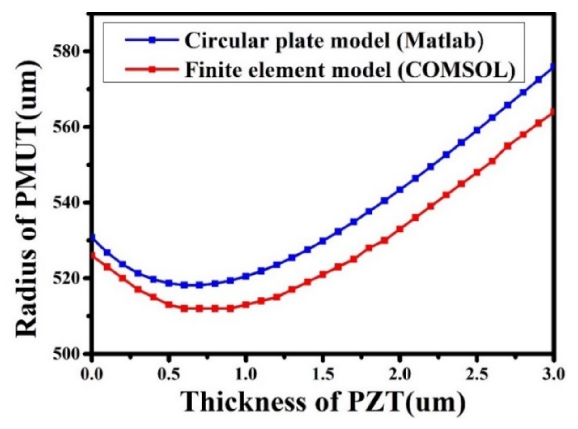
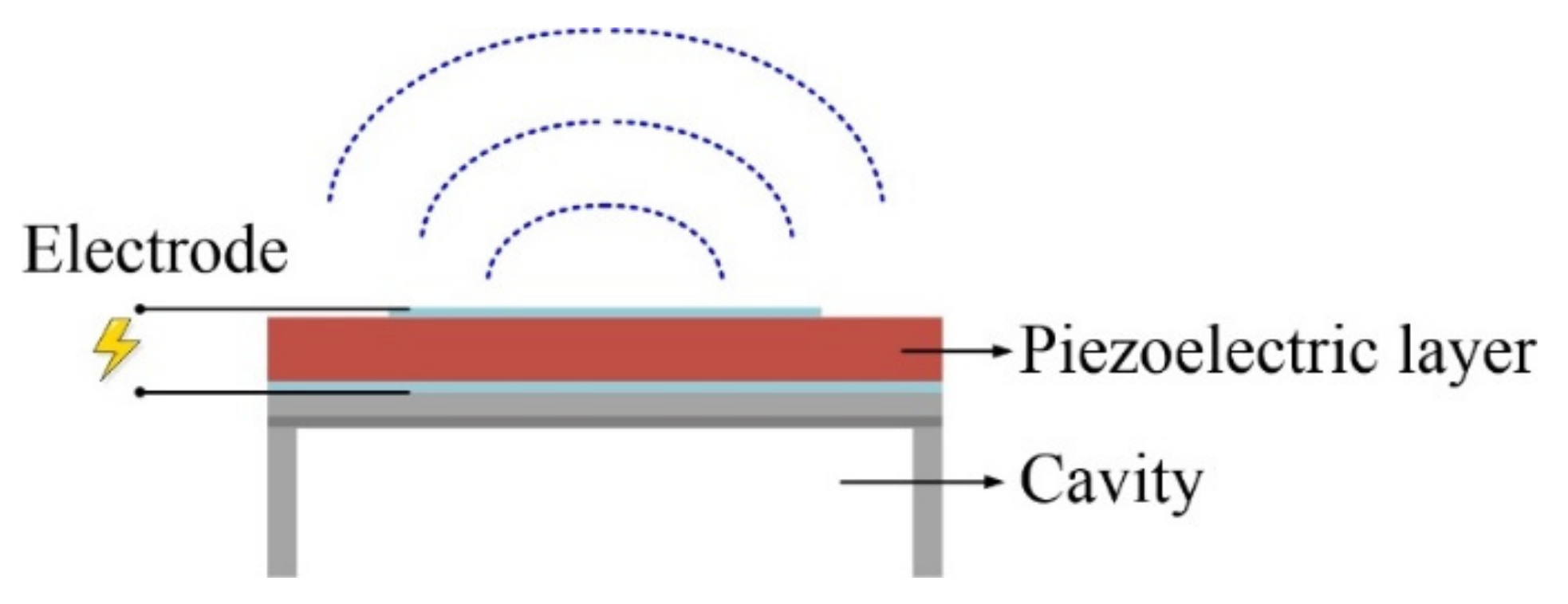
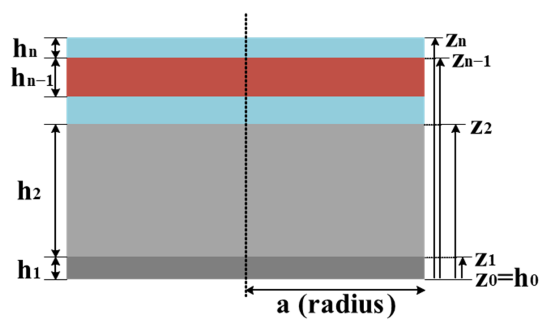
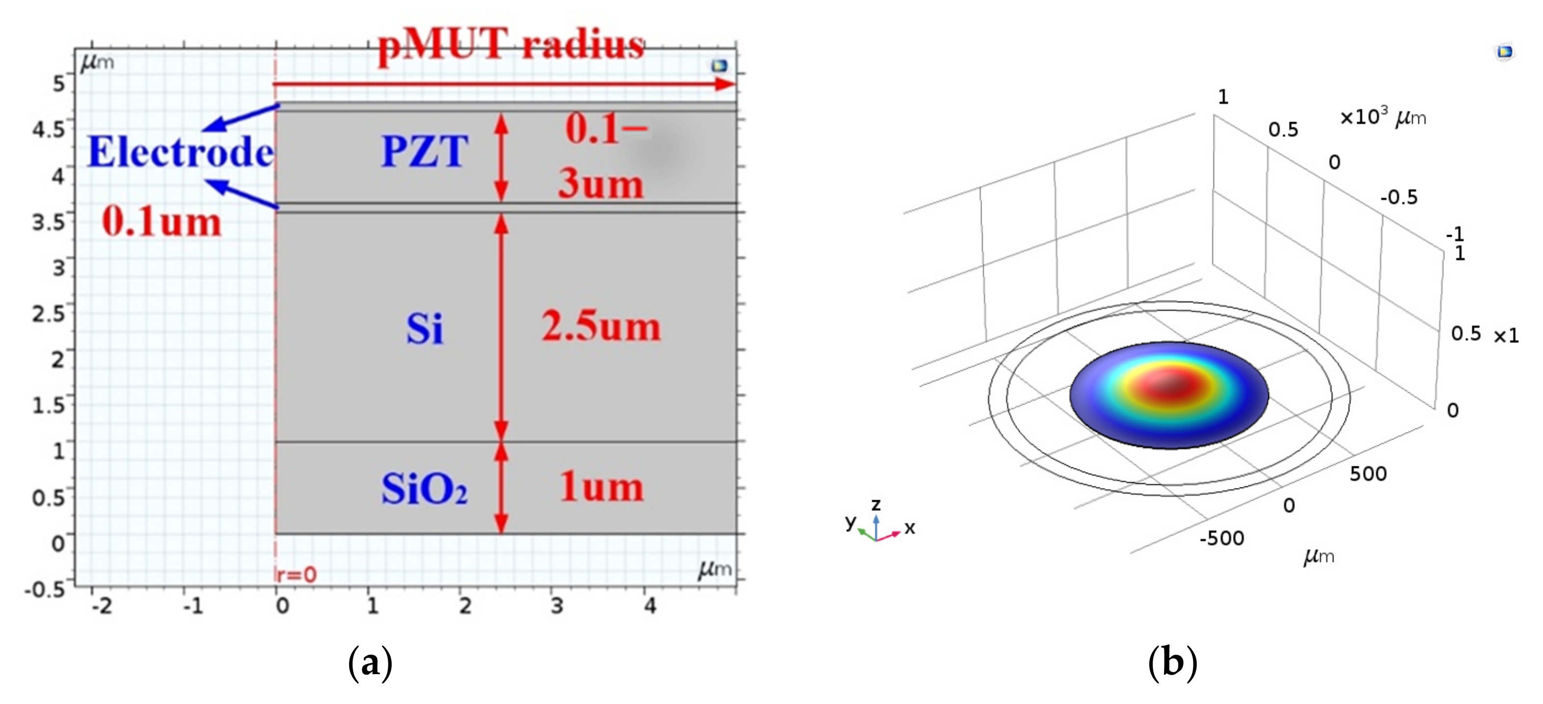
2.1. Design and Simulation of the 40 kHz PZT pMUT
Figure 1 shows the structure of pMUT, which is based on the flexural motion of a thin membrane coupled with a piezoelectric film. The pMUT in this study was composed of a 2.5 μm Si layer, a 1 μm SiO2 layer, and a PZT layer with different thicknesses. To achieve a resonance frequency of 40 kHz, the circular plate model and FEM were used to calculate the thickness of the PZT, which varied depending on the fabrication method.
Figure 1.
Structure of the pMUT device.
Considering the pMUT as a circular plate, the resonance frequency can be calculated by Equations (1)–(3) and Table 1.
where a is the radius of pMUT; D is the flexural rigidity, which is related to Young’s modulus (E), Poisson’s ratio (ν), coordinate of each layer (zi), and neutral axis zN [,]; I0 is surface density; and λ stands for the axisymmetric vibration mode constant. In this research, the circular plate model is analyzed with MATLAB, as shown in Figure 2.
Table 1.
The parameters of each layer in the pMUT.
Figure 2.
Circular plate model design structure of pMUT.
Finite element analysis is a numerical method for solving engineering and physical problems. First, the structure is cut into smaller, more simplified, and interconnected units, called finite elements. Then, the differential equations and boundary values of each element are calculated to analyze various physical phenomena of the overall structure. Since the pMUT in this study is in the shape of a rotationally symmetric disk, the 2D axisymmetric modeling in COMSOL can be used to perform a three-dimensional simulation to reduce the amount of computation. As shown in Figure 3a, the 1 μm SiO2 and 2.5 μm Si are the structural layers and so are the upper and lower electrodes. The thickness of PZT varied from 0.1 μm to 3 μm with 0.1 μm steps. Figure 3b shows the finite element model after rotating the symmetry axis.
Figure 3.
FEM of the pMUT device: (a) design structure of the pMUT; (b) finite element model of the pMUT.
As shown in Figure 4, both the circular plate model and the FEM suggest that for a pMUT with a resonance frequency of 40 kHz, the radius would range from 510 to 590 μm when the thickness of the PZT layer increased from 0.1 μm to 3 μm.
Figure 4.
Simulated pMUT radius versus PZT thickness to achieve a 40 kHz resonance frequency.
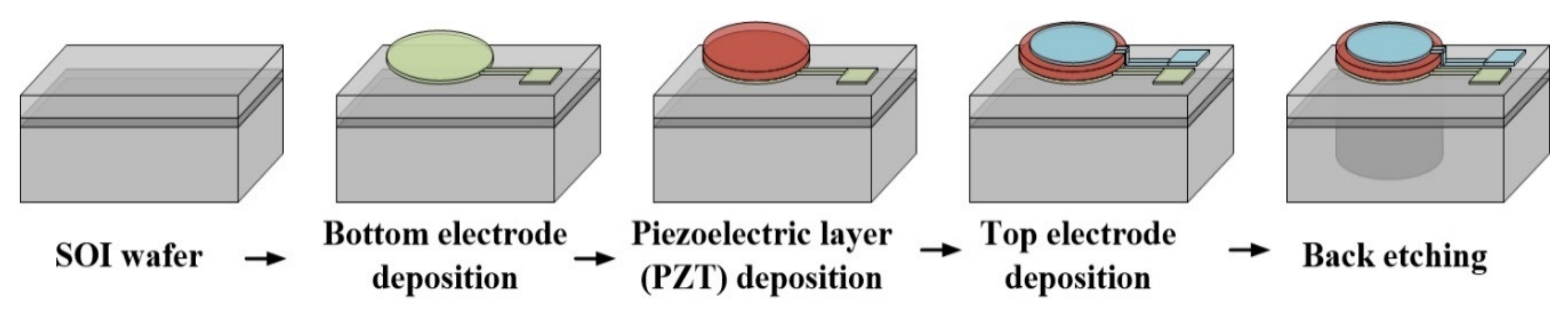
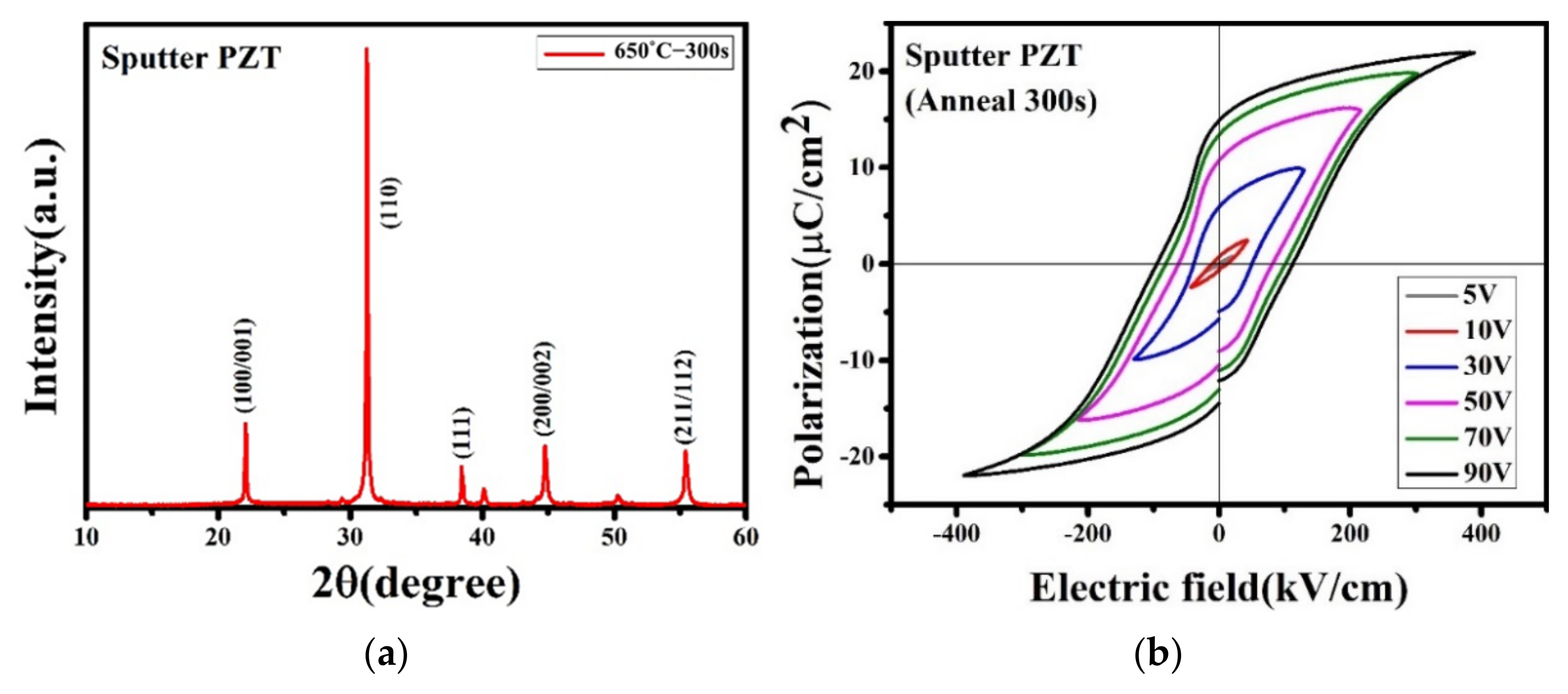
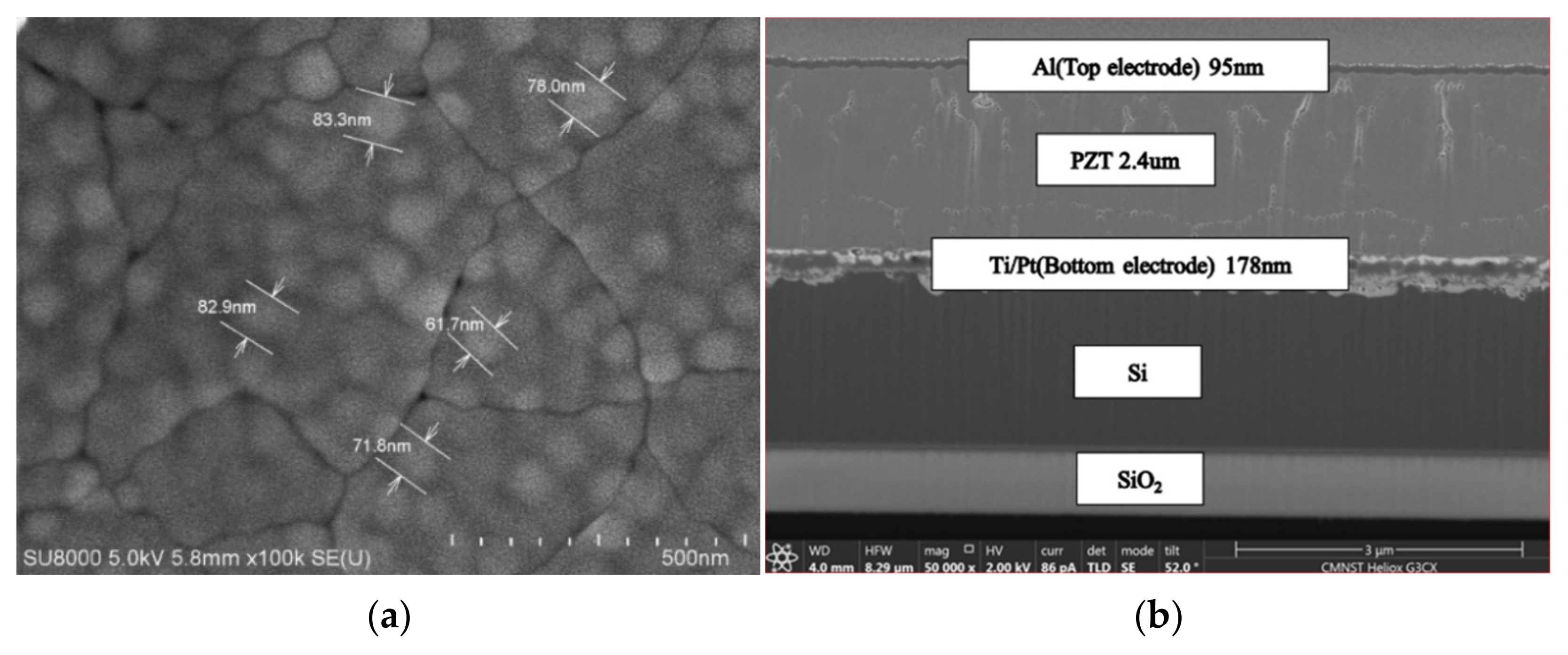
2.2. Fabrication and Analysis of the PZT pMUT
Figure 5 shows the process flow of fabricating the proposed pMUT. First, SOI wafers were used as the substrates and the oxide layer as the stop layer for deep etching. As for the bottom electrode, 20 nm Ti/100 nm Pt was deposited before PZT sputtering. The PZT target was purchased from commercial vendors (SWI, purity > 99.9%). The PZT layer was deposited at room temperature by RF sputtering in a high vacuum of 5 × 10⁻⁷ Torr. The deposition rate and thickness were monitored and controlled by quartz crystal oscillators and further calibrated by surface profiling (KLA Tencor, Alpha-Step IQ). The deposition rate of PZT was 300 nm/h under the condition of 350 W RF power and 40 sccm Ar. Since the 2.4 μm PZT fabricated by sputtering was deposited at room temperature, it had to be annealed at 650 °C to be crystallized and polarized. After that, 100 nm Al was deposited as the top electrode. The radius of the top electrode was 67% of that of the pMUT to optimize the performance. Lastly, the circular plate was released by creating a cavity underneath the pMUT using inductively coupled plasma etching under a 200 W power for 1.5 h.
Figure 5.
Fabrication process flow of the proposed PZT pMUT.
Phase and crystalline structure analyses of the PZT were performed with X-ray diffraction (XRD). The hysteresis loops of the PZT were measured by a ferroelectric tester. The particle size of the PZT film and the cross-section of the fabricated pMUT were observed by a scanning electron microscope (SEM). The resonance frequency of each fabricated pMUT was measured by a laser Doppler vibrometer.
The output pressure of each pMUT was measured by a standard microphone (B&K 4954A) when driven with its respective resonance frequency. The measured output sound pressure was applied in the simulation of the pMUT array using MATLAB. As shown in Figure 6, the number of pMUTs, array size, and position of ultrasound focal point were first defined. The phase delay of each pMUT could be calculated using the distance between each element and the focal point. By analyzing the acoustic pressure generated by each pMUT, the pressure distribution of a specific plane can be found. This simulation yielded the dimensions and elements of a pMUT array necessary for successful ultrasonic haptic feedback.
Figure 6.
Structure of the sound pressure simulation for the pMUT array.
3. Results and Discussion
3.1. Device Characteristics
Figure 7 presents the properties of the sputtering-fabricated PZT. The XRD pattern indicates that the pyrochlore phase was almost eliminated and the perovskite phase was dominant. It also shows that the PZT film exhibits mixed orientations of the (100), (110), and (111) directions. The P-E curves show remarkably hysteretic behaviors, and the remnant polarization is 21.931 μC/cm2. The SEM image in Figure 8a shows the surface morphologies of the PZT film with an average grain size of 75.54 nm. Figure 8b illustrates the cross-section of the pMUT with the actual thickness of each layer.
Figure 7.
Properties of the sputtered PZT: (a) XRD pattern; (b) P-E hysteresis loop.
Figure 8.
SEM image: (a) surface of the PZT; (b) cross-section of the pMUT.
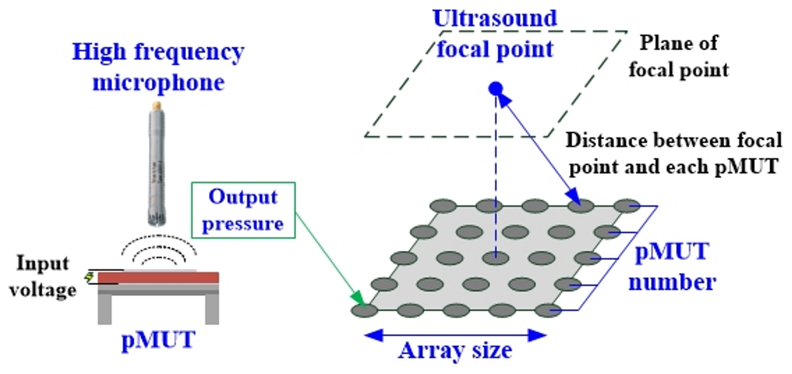
3.2. Acoustic Characteristics
For the fabricated pMUTs with a radius from 700 μm to 1000 μm, the resonance frequencies were between 29 kHz and 65 kHz, as shown in Figure 9. The trend of the measured resonance frequencies fits well with the analytical model and the FEM. As Figure 10 presents, the output pressure of a pMUT with 1000 μm in radius is 0.227 Pa when driven with 70 Vpp and 32.9 kHz sinusoidal bursts. According to the measurement results, the ultrasound was focused at 5 cm above the center of the pMUT array, as shown in Figure 11, and the pressure level at that point was almost 700 Pa. The pressure field simulation of the pMUT array composed of 251 × 251 elements was performed by MATLAB (Figure 12) and was able to generate the minimum pressure required for a tactile sensation. These results proved that haptic feedback applications are possible.
Figure 9.
Resonance frequency versus pMUT radius (measured and simulated).
Figure 10.
Acoustic pressure measurement of the pMUT.
Figure 11.
Schematic of the pMUT arrays model.
Figure 12.
Acoustic pressure distribution in the pMUT array simulation.
4. Conclusions
In this study, a platform for fabricating PZT pMUTs dedicated to ultrasound haptic feedback applications was performed, including the procedures of design, fabrication, and simulation. The optimized PZT layer demonstrated good perovskite crystallization and remnant polarization. The resonance frequency of the pMUT was selectable and the measured output pressure could reach 0.227 Pa when driven with 70 Vpp sinusoidal bursts. Furthermore, the array composed of 251 × 251 pMUTs was able to generate sufficient acoustic pressure on the focal point to create a haptic sensation during the simulation. Through characteristic measurement and output pressure simulation, the proposed pMUT demonstrated its potential of being applied to ultrasound haptic technology.
Author Contributions
Conceptualization, Y.-H.L. and C.-H.H.; software, H.-Y.S.; validation, H.-C.L. and C.-Y.L.; formal analysis, Y.-H.L.; investigation, Y.-H.L.; writing—original draft, Y.-H.L.; writing—review and editing, C.-H.H.; supervision, Y.-H.W. All authors have read and agreed to the published version of the manuscript.
Funding
This research received no external funding.
Data Availability Statement
The data are available from the authors upon request.
Acknowledgments
The authors would like to thank the Taiwan Semiconductor Research Institute (TSRI) and the Ministry of Science and Technology (MOST) for supporting FAB facilities and funding under JDP111-Y1-041 and MOST 109-2923-E-006-002-MY3.
Conflicts of Interest
The authors declare no conflict of interest.
References
- Carter, T.; Seah, S.A.; Long, B.; Drinkwater, B.; Subramanian, S. UltraHaptics: Multi-point mid-air haptic feedback for touch surfaces. In Proceedings of the 26th Annual ACM Symposium on User Interface Software and Technology, UIST 2013, St. Andrews, UK, 8–11 October 2013; Association for Computing Machinery: New York, NY, USA, 2013; pp. 505–514. [Google Scholar]
- Rakkolainen, I.; Freeman, E.; Sand, A.; Raisamo, R.; Brewster, S. A Survey of Mid-Air Ultrasound Haptics and Its Applications. IEEE Trans. Haptics 2020, 14, 2–19. [Google Scholar] [CrossRef] [PubMed]
- Iwamoto, T.; Tatezono, M.; Shinoda, H. Non-contact method for producing tactile sensation using airborne ultrasound. In Proceedings of the 6th International Conference on Haptics: Perception, Devices and Scenarios, EuroHaptics 2008, Madrid, Spain, 10–13 June 2008; Springer: Berlin/Heidelberg, Germany, 2008. LNCS. Volume 5024, pp. 504–513. [Google Scholar]
- Erguri, A.S.; Huang, Y.; Zhuang, X.; Oralkan, O.; Yarahoglu, G.G.; Khuri-Yakub, B.T. Capacitive micromachined ultrasonic transducers: Fabrication technology. IEEE Trans. Ultrason. 2005, 52, 2242–2258. [Google Scholar] [CrossRef] [PubMed]
- Zahorian, J.; Hochman, M.; Xu, T.; Satir, S.; Gurun, G.; Karaman, M.; Degertekin, F.L. Monolithic CMUT-on-CMOS integration for intravascular ultrasound applications. IEEE Trans. Ultrason. 2011, 58, 2659–2667. [Google Scholar] [CrossRef] [PubMed] [Green Version]
- Jiang, X.; Lu, Y.; Tang, H.Y.; Tsai, J.M.; Ng, E.J.; Daneman, M.J.; Boser, B.E.; Horsley, D.A. Monolithic ultrasound fingerprint sensor. Microsyst. Nanoeng. 2017, 3, 17059. [Google Scholar] [CrossRef] [PubMed] [Green Version]
- Qiu, Y.; Gigliotti, J.V.; Wallace, M.; Griggio, F.; Demore, C.E.; Cochran, S.; Trolier-McKinstry, S. Piezoelectric Micromachined Ultrasound Transducer (PMUT) Arrays for Integrated Sensing, Actuation and Imaging. Sensors 2015, 15, 8020–8041. [Google Scholar] [CrossRef] [PubMed] [Green Version]
- Wang, H.; Chen, Z.; Yang, H.; Jiang, H.; Xie, H. A Ceramic PZT-Based PMUT Array for Endoscopic Photoacoustic Imaging. J. Microelectromechanical Syst. 2020, 29, 1038–1043. [Google Scholar] [CrossRef] [PubMed]
- Song, R.; Richard, G.; Cheng CY, Y.; Teng, L.; Qiu, Y.; Lavery, M.P.J.; Trolier-Mckinstry, S.; Cochran, S.; Underwood, I. Multi-Channel Signal-Generator ASIC for Acoustic Holograms. IEEE Trans. Ultrason. Ferroelectr. Freq. Control. 2020, 67, 49–56. [Google Scholar] [CrossRef] [PubMed] [Green Version]
- Cheng, C.Y.; Dangi, A.; Ren, L.; Tiwari, S.; Benoit, R.R.; Qiu, Y.; Lay, H.S.; Agrawal, S.; Pratap, R.; Kothapalli, S.-R.; et al. Thin Film PZT-Based PMUT Arrays for Deterministic Particle Manipulation. IEEE Trans. Ultrason. Ferroelectr. Freq. Control. 2019, 66, 1606–1615. [Google Scholar] [CrossRef] [PubMed] [Green Version]
- Halbach, A.; Gijsenbergh, P.; Jeong, Y.; Devriese, W.; Gao, H.; Billen, M.; Torri, G.B.; Chare, C.; Cheyns, D.; Rottenberg, X.; et al. Display Compatible PMUT Array for Mid-Air Haptic Feedback. In Proceedings of the 20th International Conference on Solid-State Sensors, Actuators and Microsystems and Eurosensors XXXIII, TRANSDUCERS 2019 and EUROSENSORS XXXIII, Berlin, Germany, 23–27 June 2019; Institute of Electrical and Electronics Engineers Inc.: Piscataway, NJ, USA, 2019; pp. 158–161. [Google Scholar]
- Smyth, K.; Kim, S.-G. Experiment and simulation validated analytical equivalent circuit model for piezoelectric micromachined ultrasonic transducers. IEEE Trans. Ultrason. Ferroelectr. Freq. Control. 2015, 62, 744–765. [Google Scholar] [CrossRef] [PubMed] [Green Version]
- Smyth, K.; Bathurst, S.; Sammoura, F.; Kim, S.-G. Analytic solution for N-electrode actuated piezoelectric disk with application to piezoelectric micromachined ultrasonic transducers. IEEE Trans. Ultrason. Ferroelectr. Freq. Control. 2013, 60, 1756–1767. [Google Scholar] [CrossRef] [PubMed]
Publisher’s Note: MDPI stays neutral with regard to jurisdictional claims in published maps and institutional affiliations. |
© 2022 by the authors. Licensee MDPI, Basel, Switzerland. This article is an open access article distributed under the terms and conditions of the Creative Commons Attribution (CC BY) license (https://creativecommons.org/licenses/by/4.0/).