1. Introduction
The deployment of the Internet of Things (IoT) is raising many new challenges [
1,
2,
3] and requiring necessary hardware platforms to prototype and test new emerging solutions and features [
4]. In this context, reconfigurable logic becomes a useful tool for prototyping and, in several cases, for final implementations [
5,
6]. Due to the specific characteristics of IoT devices, it is possible to establish different prototyping levels in the development of such devices. Concretely, three main prototyping levels can be considered:
Standard module level. At this level, standard modules are connected for testing algorithms, protocols, communications, sensors and actuators. A paradigmatic example of this level is a microcontroller development board with communications and sensor modules [
7].
Specific module level. If additional features and optimizations are necessary, more specific modules can be required. At this level, specific micro-controllers, FPGAs for implementing hardware co-processors or combined solutions are available. An example platform supporting these features is presented in [
8].
Low-level modular prototyping. At a lower level, testing and the optimization of hardware co-processors to be implemented on a reconfigurable device or the entire system if FPGAs are the target technology for the IoT device, can be required.
Manufacturers of reconfigurable devices have developed environments and tools to ease this last prototyping level, along with embedded microprocessors, such as Nios II from Intel Corp. [
9,
10,
11] or MicroBlaze from Xilinx Inc. [
12,
13]. In this regard, Intel provides the
Platform Designer tool within its Quartus Prime environment, allowing the designer to build a complete processing system by means of a Graphical User Interface (GUI). In this GUI, a Nios II microprocessor can be instantiated, memory and I/O maps can be easily defined, and peripheral interfaces can be described [
14]. Similarly, Xilinx provides
IP integrator within Vivado, with the same features [
15].
The main disadvantage in using these tools resides in the lack of portability of the resulting designs. If the prototype is developed using Xilinx tools, the designer has to define a new processor system if they want to test the prototype on an Intel FPGA. Furthermore, software will have to be reprogrammed due to the lack of compatibility between MicroBlaze and Nios II processors. Additionally, Nios II and MicroBlaze are proprietary processors and, although there are open-source implementations, such as MB-Lite [
16], it is required to use the tool chains provided by the manufacturers. It must be also noted that both are 32-bit microprocessors that require additional memory chips when implemented on small FPGAs.
Other options offered by reconfigurable logic manufacturers include the use of new-generation System-on-Chips (SoCs) as the ZynQ family from Xilinx [
17] or the Cyclone V SE [
18] from Intel, including one or more ARM cores [
19]. In this case, these are also quite complex 32-bit microprocessors, thus, requiring off-chip memory if low-cost devices are targeted. LEON-3- [
20] and RISC-V- [
21,
22] based soft-processors have the advantage of being open-hardware, and thus they can be implemented independently of the manufacturers. Again, they are 32-bit processors requiring external memory chips when implemented on low-cost, small-size FPGAs. This need for off-chip memory leads to more complex Printed Circuit Boards (PCBs), more power consumption and more severe security issues due to the exchange of information between CPU and memory [
23,
24,
25].
As a consequence, to the best of our knowledge, there are no platforms to prototype and/or develop secure IoT devices without the need for additional off-chip memory on low-cost FPGA devices that, at the same time, provide sufficient computing resources to allow edge computing and enable portability among different manufacturers. In order to overcome all these drawbacks, this paper proposes a VHDL-described platform, based on an open-hardware 8-bit microprocessor, for the development of IoT devices and embedded systems to be implemented on FPGAs, independently of the FPGA manufacturer. The platform, named Dracon, enables the implementation of prototypes on low-cost FPGAs and development boards from different manufacturers, thus, helping to select the best implementation target for the design.
Moreover, Dracon enables the implementation of the entire IoT processing system in a single low-cost chip without the need for external memory. Therefore, the main contributions of the present manuscript can be summarized as:
A platform based on an 8-bit, open-hardware microprocessor to develop secure IoT devices on low-cost FPGAs is presented.
The presented platform, named Dracon, was entirely developed in synthesizable VHDL, without making use of any specific modules. Additionally, it is based on an 8-bit open-hardware microprocessor, T80 [
26], thus, being implementable on devices from any manufacturer.
A Minimal implementation of the platform, with the 8-bit microprocessor, one UART and 16-KB memory, requires less of 2000 LUTs, which can be implemented on low-cost, small-size FPGAs.
Dracon is modular, which makes it easy to add new modules to include hardware accelerators, cryptographic processors or arithmetic processors, or to prototype and test IP cores.
The software toolchain utilized in Dracon is based on the use of free tools, and thus not dependent on any manufacturer.
Software developed for Dracon is portable, and it can run on the platform independently of the hardware device used for its implementation. This leads to saving time and costs when porting the software to devices from other manufacturers, while easing the change of provider when necessary due to economic and/or efficiency criteria.
Dracon does not require off-chip additional memory, thus, allowing the implementation of secure IoT devices with low-cost FPGAs.
The selection of a powerful Z80-compatible [
27] microprocessor enables edge computing applications on the developed IoT devices.
The rest of the paper is organized as follows:
Section 2 presents the Dracon platform description,
Section 3 describes the basic functions of the Dracon firmware,
Section 4 is devoted to the software tool-chain for programming Dracon,
Section 5 shows some applications examples, and
Section 6 provides the conclusions of the paper.
2. Dracon Description
The Dracon platform is built upon a T80 [
26] microprocessor, which is an open-source clone of the popular 8-bit Z80 microprocessor from Zilog [
27]. The use of T80 as the kernel of Dracon presents some advantages with respect to other platforms, which can be summarized as follows:
T80 is open-source and VHDL-described. Therefore, it can be implemented on FPGAs from any manufacturer. Moreover, it can be modified for research and optimization purposes.
It has been widely tested and used in different projects, such as FPGA Arcade [
28] and education [
29], providing a proven compatibility with the original Z80.
Its low memory requirements enable the implementation of complex applications on low-cost FPGAs without requiring external memory, which is essential for applications needing high levels of security. In this sense, MicroBlaze and Nios II are 32-bit microprocessors, thus, requiring external memory when used on low-cost FPGAs.
There are several software resources available for software development, such as the CP/M operating system [
30], the tniASM assembler [
31], the SDCC compiler [
32] and the Z80Emu emulator [
33] (currently, the Z80 microprocessor remains in production by Zilog, being extensively used in the development of embedded systems [
34]).
When compared to other 8-bit soft-core processors, those based on Z80 require more area resources than ones based on 8080-, 8085- or 8051-instruction sets [
35]; however, the available resources in modern low-cost FPGAs make the Z80 an affordable option, while it presents great advantages in terms of arithmetic features, block instructions and number of registers [
36]. A special mention is deserved in the case of PicoBlaze [
37], a tiny 8-bit processor developed by Xilinx that has been ported to FPGAs of other manufacturers. It requires very limited resources, however, at the cost of a reduced address space (1 K addresses in the case of PicoBlaze-3 and 4 K addresses for PicoBlaze-6) [
35]. In this sense, T80 allows the execution of much more complex programs, thus, enabling the development of more sophisticated edge computing applications.
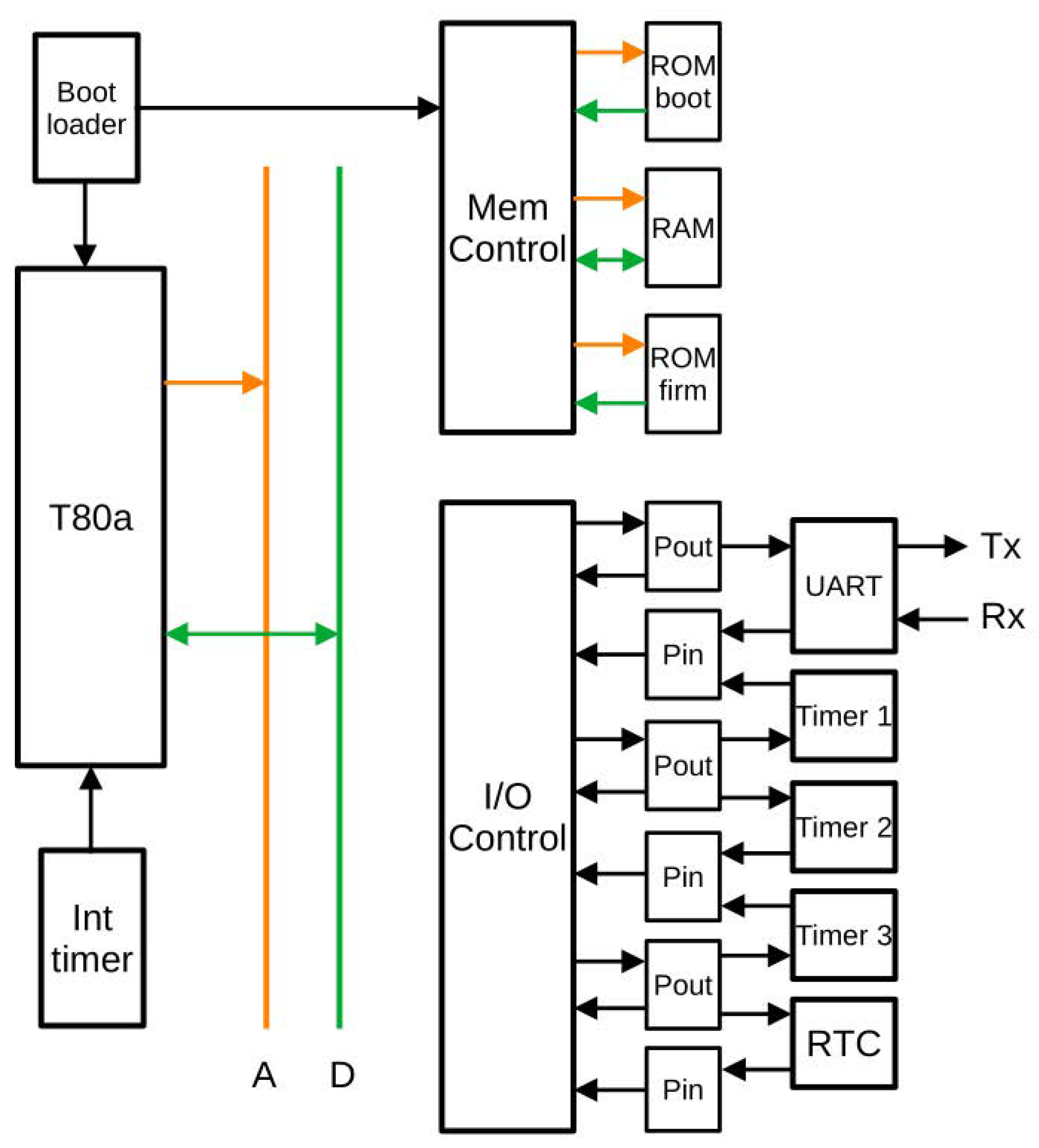
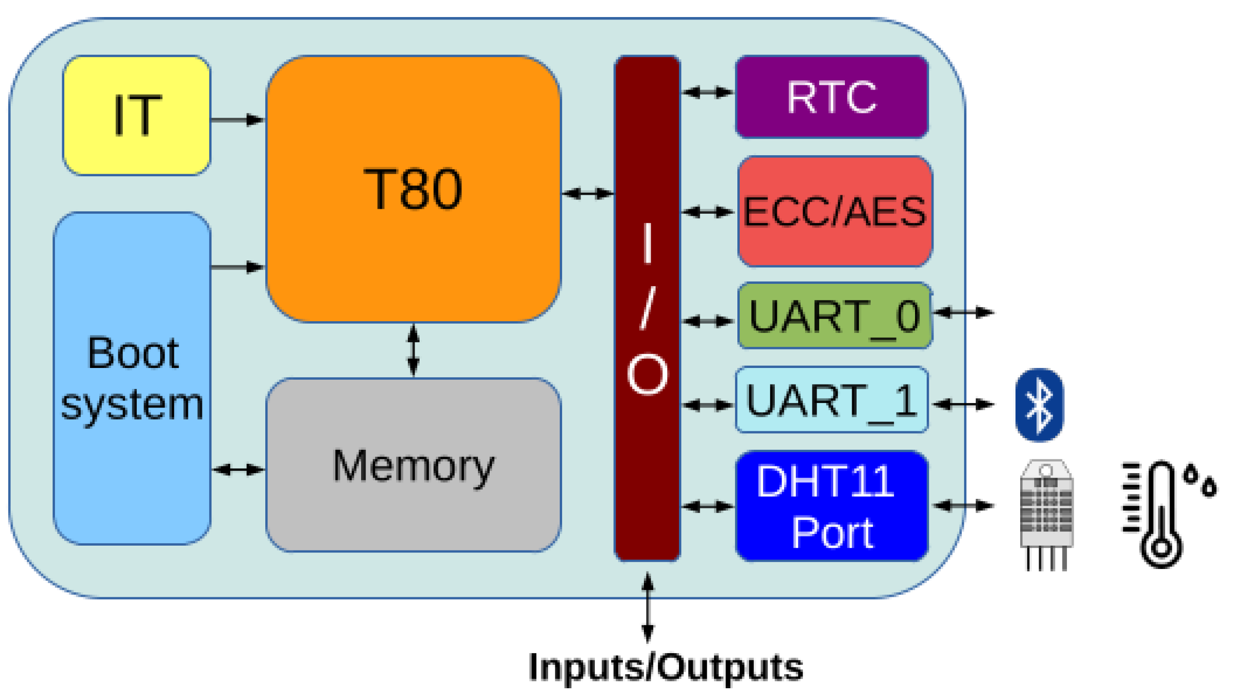
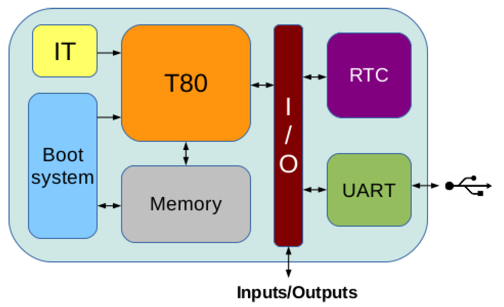
Figure 1 presents a summarized diagram of the Dracon platform, including the T80 CPU, internal memory, boot system, Interrupt Timer (IT), Real Time Clock (RTC) and a UART to communicate with the outside. The next subsections will describe each of the internal subsystems in more detail.
2.1. Dracon CPU
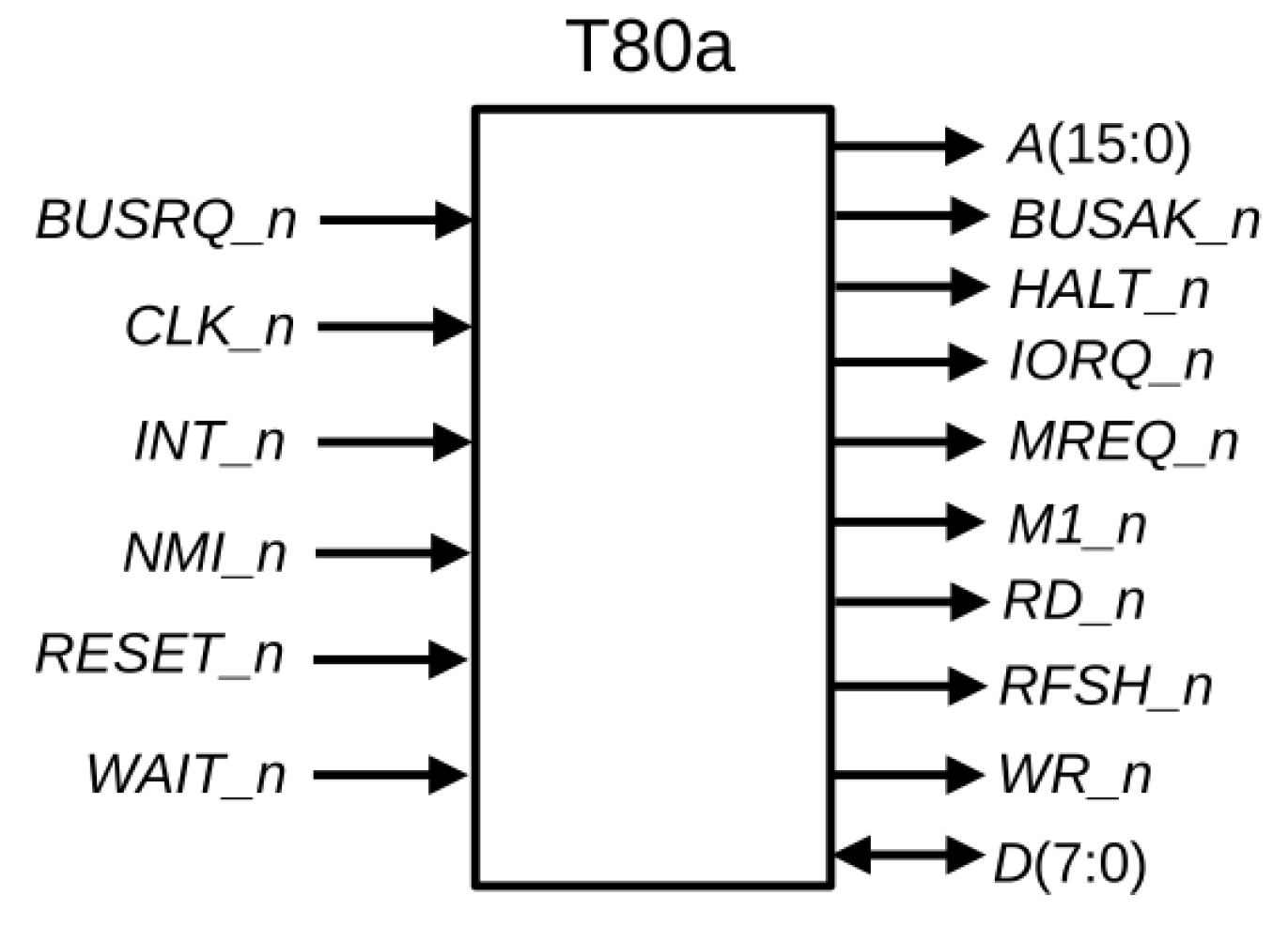
Figure 2 presents the T80 microprocessor pinout, where it is shown that it has a 16-bit address bus (
A) and an 8-bit bidirectional data bus (
D). Therefore, the T80 can address a maximum of 64 KB of RAM, organized in 8-bit words. Regarding I/O, the T80 CPU can address 256 inputs/outputs using the
IORQ_n and
MEMRQ_n signals.
RD_n and
WR_n signals control the bidirectional data bus.
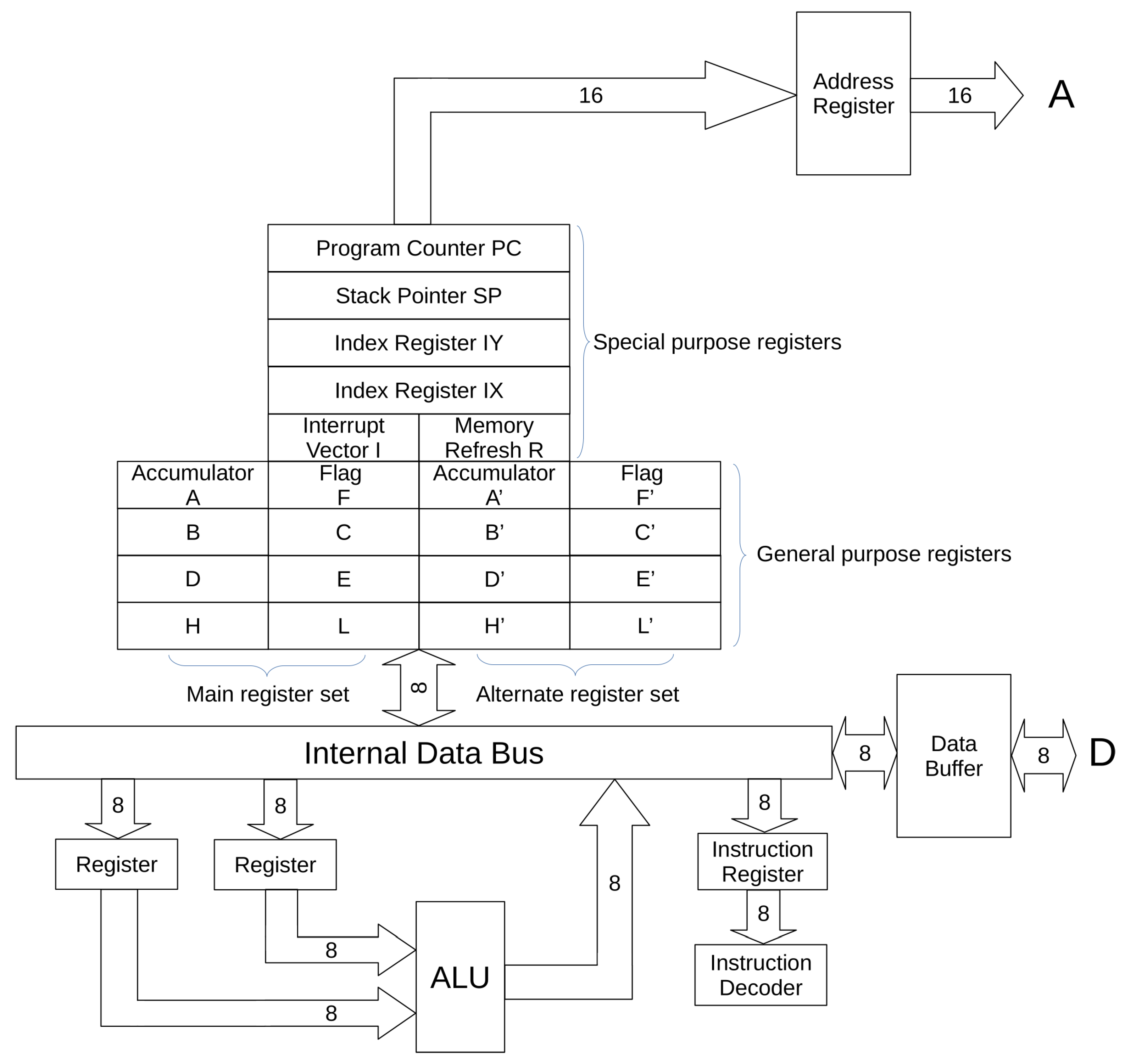
Figure 3 shows the internal structure of the T80 CPU, which includes two complete sets of 8-bit general purpose registers that ease changes of context. Moreover, 8-bit registers are paired together, forming 16-bit registers (as an example, 8-bit H and L registers are grouped into the 16-bit HL register), thus, incorporating 16-bit arithmetic and addressing. Due to the compatibility with the Z80, detailed information regarding the T80 instruction set can be found in [
27].
Table 1 shows implementation results on different FPGAs from Altera/Intel, Xilinx/AMD and Lattice Semiconductors, where Spartan 7 [
38], Artix 7 [
38] and Cyclone V [
39] devices have 6-input LUTs, while Cyclone IV [
40] and MachXO3 [
41] have 4-input LUTs. Implementations presented in
Table 1 do not make use of any blocks of RAM, multipliers or DSP resources. The tools used for each FPGA implementations are the following:
Intel FPGAs (Cyclone IV and Cyclone V SE): Quartus Prime 21.1 [
42].
Xilinx Spartan 7 and Artix 7 FPGAs: Vivado 2020.2 [
43].
Lattice Semiconductors FPGAs: Diamond 3.12. [
44]
Figure 3.
T80 internal structure, based on figures by Thomas Scherrer, adapted with permission from [
45]. Copyright 1995, Zilog Inc.
Figure 3.
T80 internal structure, based on figures by Thomas Scherrer, adapted with permission from [
45]. Copyright 1995, Zilog Inc.
Table 2 shows implementations of other 8-bit microprocessors from different manufactures and implemented on different FPGAs, reproduced from [
35]. Although technologies and software tools are different for each microprocessor, it is possible to establish a fair comparison with results from
Table 1 by focusing on the row corresponding to Cyclone IV devices, as their LEs are based on 4-input LUTs. Microprocessors in
Table 2 have been developed by Digital Core Design (DCD) [
46] and Xilinx. The DF6811 CPU is an 8-bit microcontroller IP core compatible with the Motorola 68HC11 [
47]. This CPU has less number of registers and a reduced set of instructions compared to the T80, while requiring similar area.
Similar conclusions can be derived for both DR8051 and DP8051, based on the 8051 microcontroller from Intel [
48]. Special attention is required in the case of DFPIC1655X, based on the PIC1655 microcontroller by Microchip [
49] and Picoblaze [
37] from Xilinx. They have low area requirements; however, they are oriented to simple control applications without complex arithmetic support, which makes them not able to support neither an operating system nor the execution of complex applications for edge computing. The analysis of these results reaffirms our selection of T80 as the best trade-off between available features and reduced area requirements to build the Dracon platform. Moreover, T80 is open hardware, thus, enabling portability among devices from different vendors, as it has been previously commented.
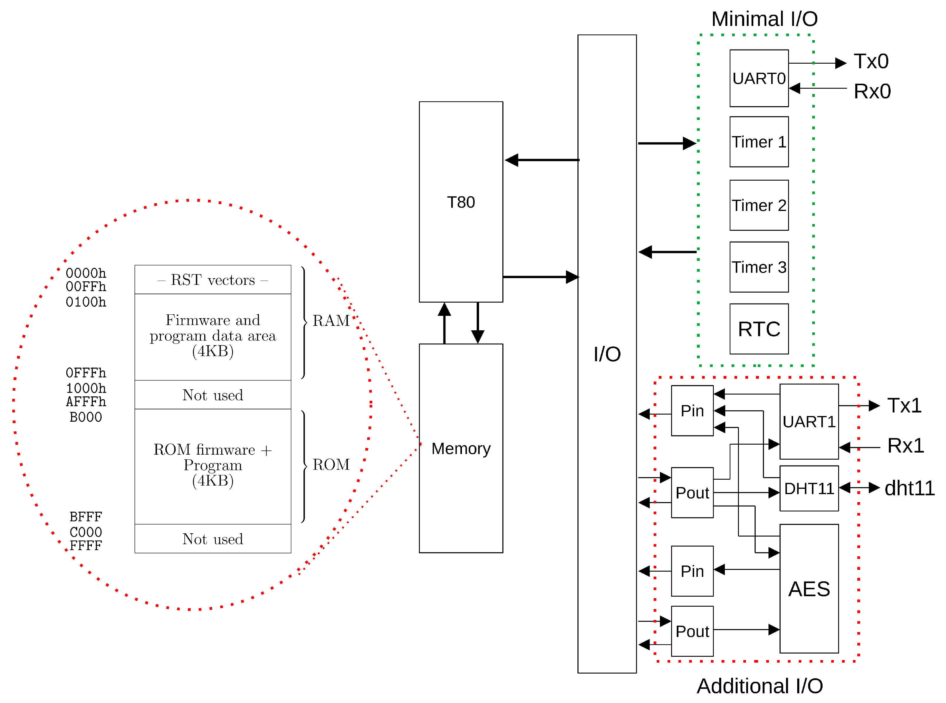
2.2. Dracon Memory Map
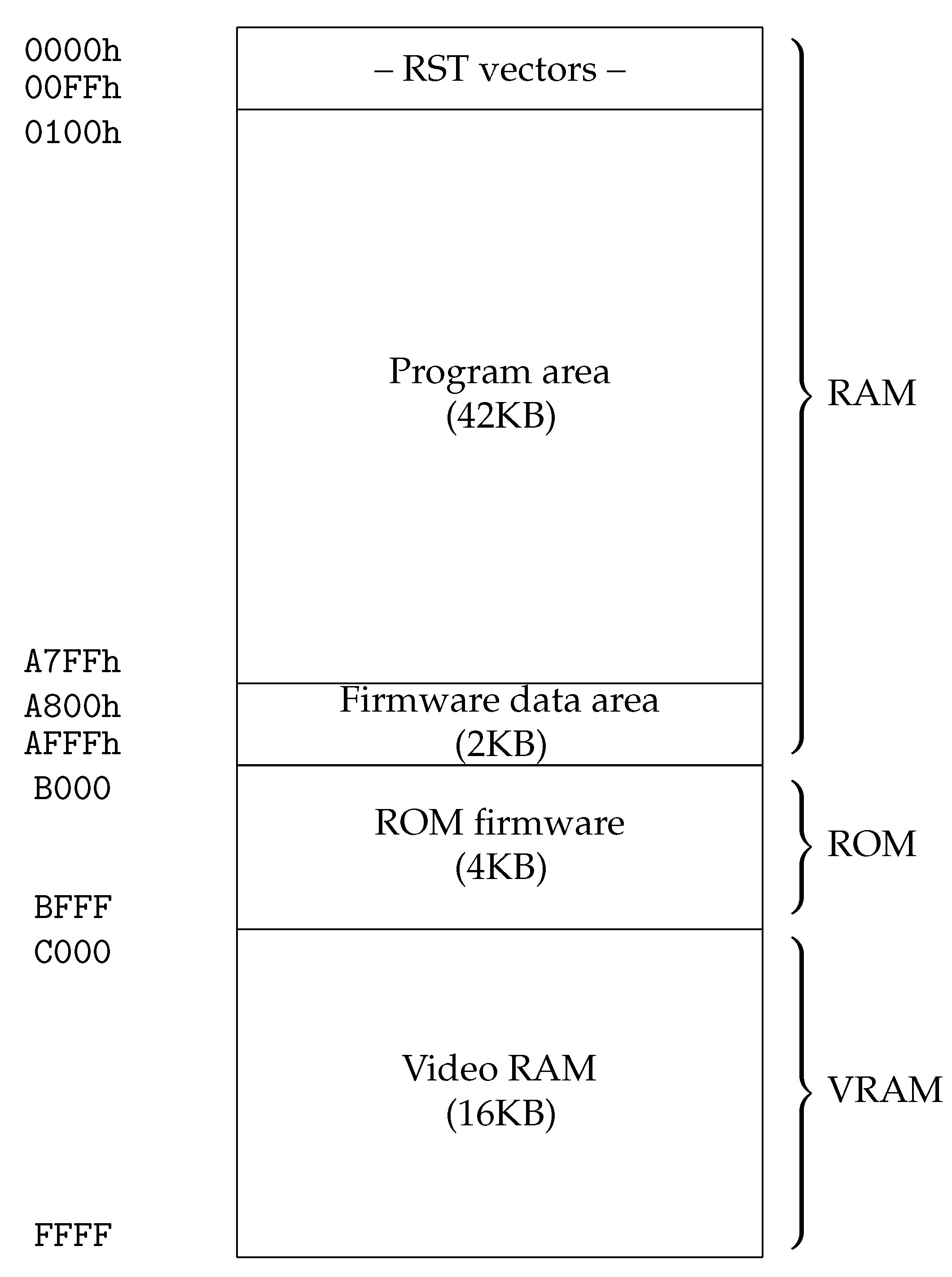
As discussed above, the T80 can address a maximum of 64 KB. The memory map provides the general organization of the system and it will largely define its capabilities. The complete memory map of Dracon is shown in
Figure 4, where 42 KB of RAM, 16 KB of video-RAM and 4 KB of ROM are installed. The 16-KB video RAM enables generating a 16-color, 80 × 50-text VGA mode with 640 × 480 resolution at 50 Hz (640 × 400 effective resolution). Furthermore, a 16-color, 160 × 200 graphical mode over the standard 640 × 480 at 50 Hz mode is available. These features can be achieved on FPGAs with enough double-port blocks of RAM memory. Furthermore, a character generator ROM is required for the text mode and the corresponding sync and video control subsystems. Memory is internally organized in 4-KB blocks, as it will be detailed in the next subsection.
This memory map presents two main advantages: first, the position of ROM allows to boot the CP/M operating system (it requires access to the first memory addresses) and, second, the memory map is easy to adapt if the system has less RAM available.
2.3. Memory Subsystem
From the memory map, it is clear that the memory subsystem has to manage RAM and ROM memory blocks. Furthermore, the Dracon platform has to be adaptable to systems with low memory resources, thus, being convenient to divide memory in several blocks and “install” the memory block required by the system under implementation. If memory is divided into a large number of blocks, more multiplexers will be required to select these blocks. On the contrary, a large block size implies a lack of flexibility to adapt Dracon to the available memory. A block size of 4 KB represents a good trade-off between flexibility and additional logic to manage those memory blocks, thus, being the block size selected for the Dracon implementation. The memory controller, when using 16 KB of RAM and 4 KB of ROM, requires only 34 6-input LUTs (Spartan 7 FPGA).
2.4. I/O Subsystem
The I/O subsystem provides access to the different peripherals connected to the T80 CPU. At a minimum, the Dracon platform provides one UART for programming and controlling the platform, a Real Time Clock (RTC) allowing to synchronize Dracon with the external world and an Interrupt Timer (IT) for generating regular interrupts in the T80. In order to maintain a trade-off between complexity and flexibility, the 256 possible input/outputs were organized in groups of four inputs or outputs.
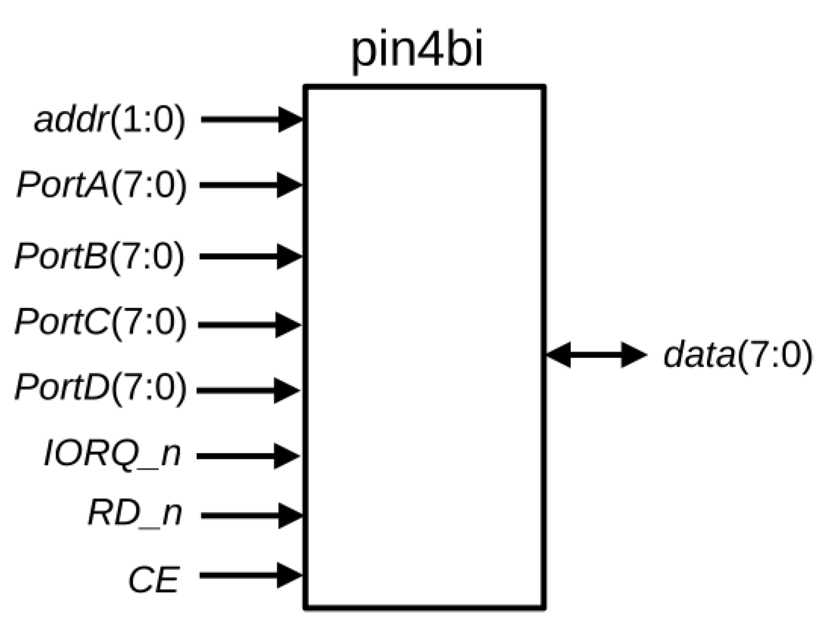
Figure 5 shows the
pin4bi block, implementing four input ports. It has four 8-input ports (
portA,
portB,
portC and
portD), one 2-bit selection input (
addr) and one 8-bit bi-directional port to access the data bus of the T80 CPU. Moreover,
CE,
IORQ_n and
RD_n provide the control signals required to enable port reading. The implementation of the
pin4bi requires nine LUTs on Spartan 7 FPGAs.
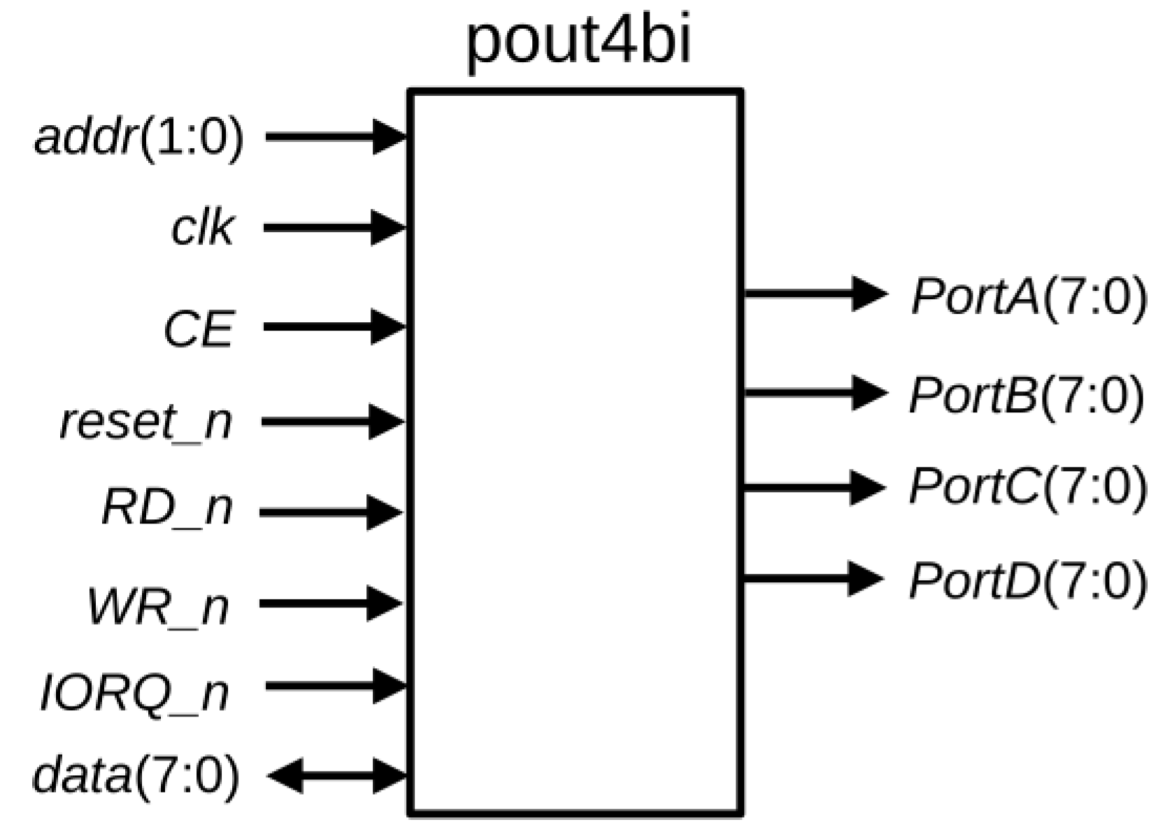
Similarly, the
pout4bi block shown in
Figure 6 implements four 8-bit output ports. These ports are registered in order to ease synchronization with peripherals, and
pout4bi requires 32 LUTs on a Spartan 7 FPGA. Note that the
RD_n signal allows to also read internal registers of
pout4bi.
2.5. Dracon Minimal Peripherals
As commented above, the minimal peripherals included in Dracon are a configurable UART, an RTC and an IT. The UART allows to communicate with Dracon, in particular, with the Monitor Program included in the Dracon firmware. Through this Monitor, it is possible to upload and execute programs on the Dracon platform. This configurable UART allows to select different baud rates and adapt Dracon communications to the clock frequency used in the target device. The RTC block provides a 32-bit counter updated every second. The IT generates a pulse every millisecond, generating an interrupt through the INT_n input of the T80. The overall I/O system with minimal peripherals requires 322 LUTs in a Spartan 7 FPGA.
2.6. Boot Subsystem
Dracon includes, by default, a Monitor-like operating system in the firmware ROM, which will be detailed in the next section; however, in the case of using external storage, the CP/M or MP/M operating systems can be also utilized [
30]. In order to allow different operating systems to boot and take control of the Dracon platform, the ROM is located at the B000h address but, after power-on, the T80 starts executing instructions at 0000h. Therefore, a boot system is required for transferring from a ROM or from a external device the first instructions to be executed. By default, the boot system transfers a jump instruction to the B000h address, where the Dracon firmware is located. The Dracon default boot system performs the following actions after power on, or after hard reset:
Maintain T80 in reset state, setting RESET_n input to ’0’.
Transfer from boot ROM to 0000h the Z80 instruction “JP B000h”.
Set RESET_n input to ’1’, thus, starting T80 operation.
After these actions, the Dracon firmware starts initializing peripherals and executing the Monitor program.
Figure 7 shows a detailed block diagram of the described minimal Dracon platform (not including VGA support).
Table 3 shows implementation results of the minimal Dracon (mDracon) platform, which requires only 1515 LUTs on a Spartan 7 FPGA, or 1210 ALMs on an Intel Cyclone V. Note that Dracon operates at an standard clock frequency of 25 MHz in order to achieve good performance while maintaining low power consumption. Proposed realizations use built-in RAM blocks to implement the 4-KB ROM and the 16-KB RAM in minimal Dracon. The memory resources available for each type of FPGA can be found in [
50] for Spartan 7 and Artix 7 FPGAs, in [
40] for Cyclone IV devices, in [
39] for Cyclone V devices and in [
51] for MachXO3 devices. As an example, an implementation of Dracon for Spartan 7 FPGAs on the Cmod-S7 board [
52] can be downloaded from [
53].
If these results are compared to those from
Table 1, the additional modules added to the T80 CPU to build this minimal Dracon platform require only around 290 LUT6s on Spartan 7 and Artix 7 FPGAs. In the case of devices from Intel, 565 additional LEs are required on Cyclone IV and 259 ALMs on Cyclone V, while on MachXO3LF devices from Lattice the additional circuitry requires 773 LUT4s. Therefore, the minimal Dracon platform can be built on top of the T80 at a reduced cost.
3. Dracon Firmware
The Dracon firmware provides a minimal environment to upload programs to the RAM and to execute them. It also provides high-level functions to access the UART and RTC and a framework to install Interrupt Service Routines (ISRs). Each of these ISRs are called by default every 1 ms, allowing to poll sensors or any other peripherals without stopping the main program. After power on, the boot system transfers control to the firmware, which initializes and configures the peripherals. In this case, UART parameters must be configured for setting it to 57,600 baud. After that, the Monitor Program (MP) is started, presenting a welcome message over the UART and providing a prompt waiting for commands. The commands available in release R0.1 of the Monitor Program are:
l[address][size]. Loads [size] bytes in the [address] address, where [address] and [size] are given as four hexadecimal digits.
e[address]. Executes program at [address].
t. Shows time in milliseconds from last reset. It is updated by means of interrupts and can be used to measure executions times.
c. Shows RTC register value.
m[address]. Shows content of [address].
Apart from the MP, the firmware includes a set of function calls allowing to manage ISRs and easing the access to standard peripherals as the UART. Main firmware calls are:
CONSOLE_OUT. Outputs a character through the console (UART).
CONSOLE_IN. Reads a character from the input buffer (UART).
PRINT. Prints a string at the standard output.
READLINE. Reads a line from the standard output.
writeline_u. Writes a string plus CR-LF.
readline_u. Reads a string from the standard input until CR is detected.
register_ISR. Registers a new ISR in the system.
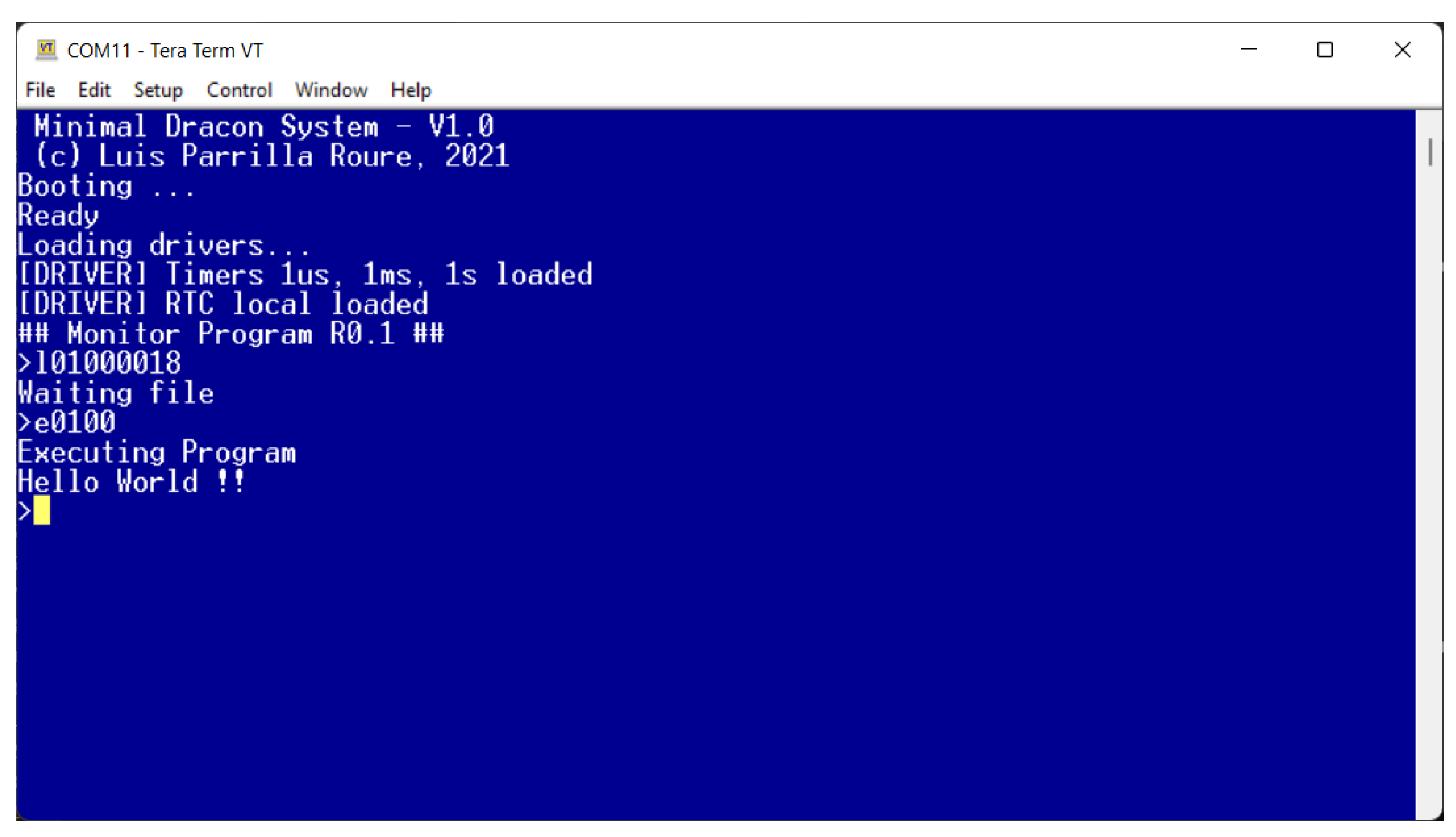
Additionally, the minimal firmware includes functions to perform fixed-point 32-bit arithmetic operations (addition, subtraction, multiplication and division). More advanced versions also include floating-point arithmetic. With these functions, the Dracon firmware provides basic infrastructure for loading, building and executing complex applications. In order to illustrate this,
Figure 8 shows an example loading and executing the “Hello World” program, which requires only 24 bytes on the Dracon platform making use of firmware [
54]. In this example, the ”Hello World” is first loaded using the “
l 01000018” command, which loads 18 h (24) bytes at the 0100h address. Then, the program is executed using the “
e0100” command on the MP.
4. Software Toolchain
In order to develop software for a given microprocessor, a tool-chain is required. In the case of Dracon, the most efficient option in terms of memory resources and execution time is using a cross Z80 assembler. The software presented in this work was developed using a freeware version of tniASM [
31], taking into account Z80 documentation [
27]. Nevertheless, the SDCC compiler [
32] can be also used for engineers preferring C programming.
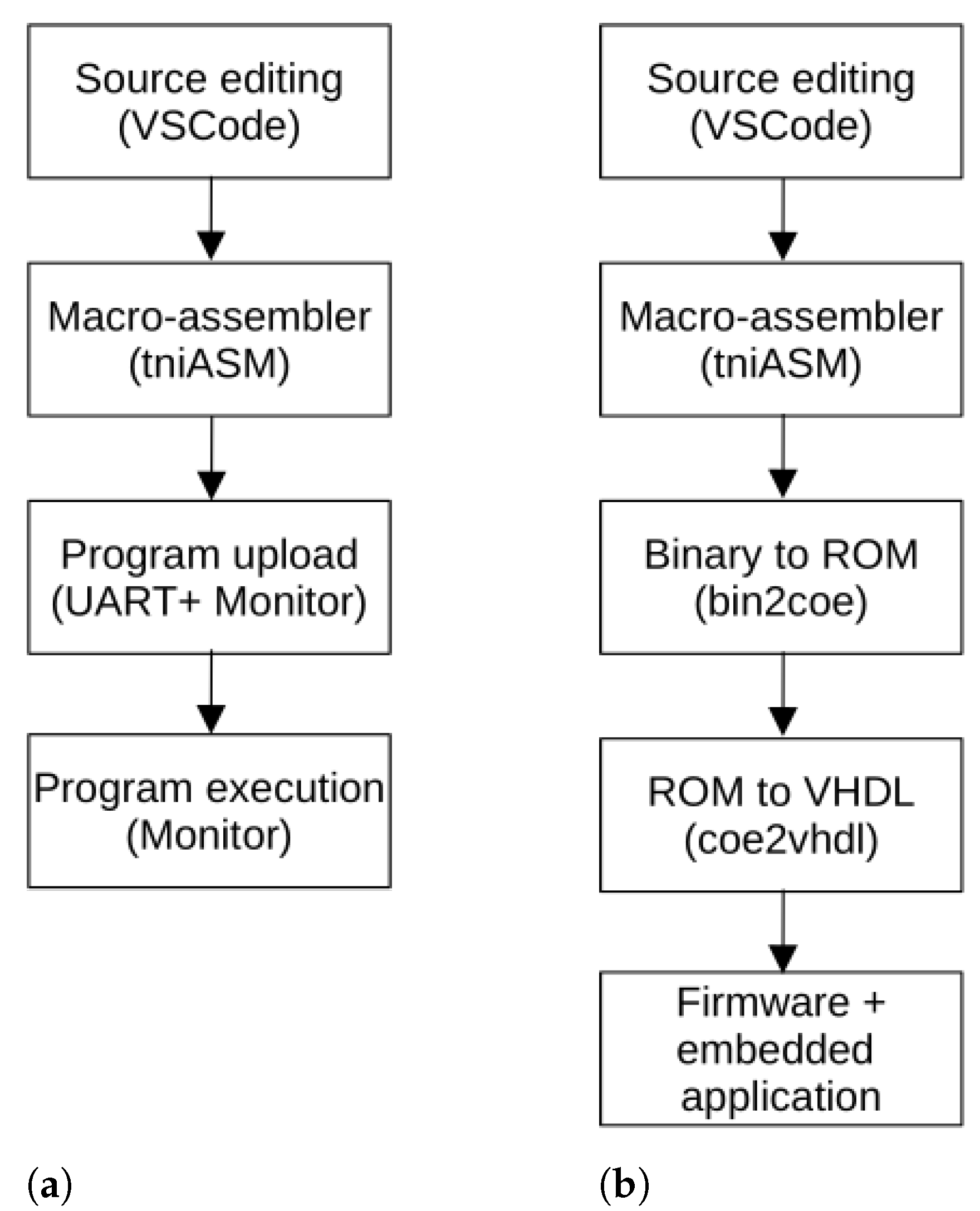
Figure 9a shows the recommended flow for building a Dracon application:
Application source code is written using a text editor supporting syntax highlighting extensions for Z80 assembler, as VSCode [
55], thus, obtaining an
.asm file. Note that this source code may take advantage of firmware calls, as commented in the previous subsection.
The source code is compiled using tniASM, generating a binary file .bin that can be executed in the Dracon platform.
The binary file containing the developed program is uploaded to Dracon trough the UART and using the “l” command available in the Monitor program.
The program is executed using the “e” command available in the Monitor program.
The development of Dracon firmware is slightly more complicated, because it has to be mapped to a VHDL description of a ROM memory. For this purpose, we developed two tools,
bin2coe and
coe2vhdl. Thus, the tool-chain for implementing a Dracon firmware, as shown in
Figure 9b, is the following:
Write the Z80 assembler source (.asm).
Assemble the firmware source using tniASM (.bin).
Convert the binary file obtained from tniASM to a memory description file in .coe format using bin2coe.
Convert the .coe file to a VHDL description using coe2vhdl tool.
Using this process, a synchronous synthesizable ROM memory is obtained, which is inferred as block RAMs by the usual FPGA tools (Quartus II from Intel/Altera, ISE/Vivado from Xilinx/AMD and Diamond from Lattice Semiconductors). This same process can be used to build an embedded application, including it in the firmware source and substituting the Monitor program by the desired application.
5. Application Examples
In this section, three applications of the Dracon platform showing its applicability and flexibility are described.
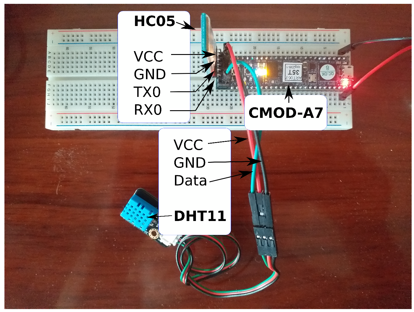
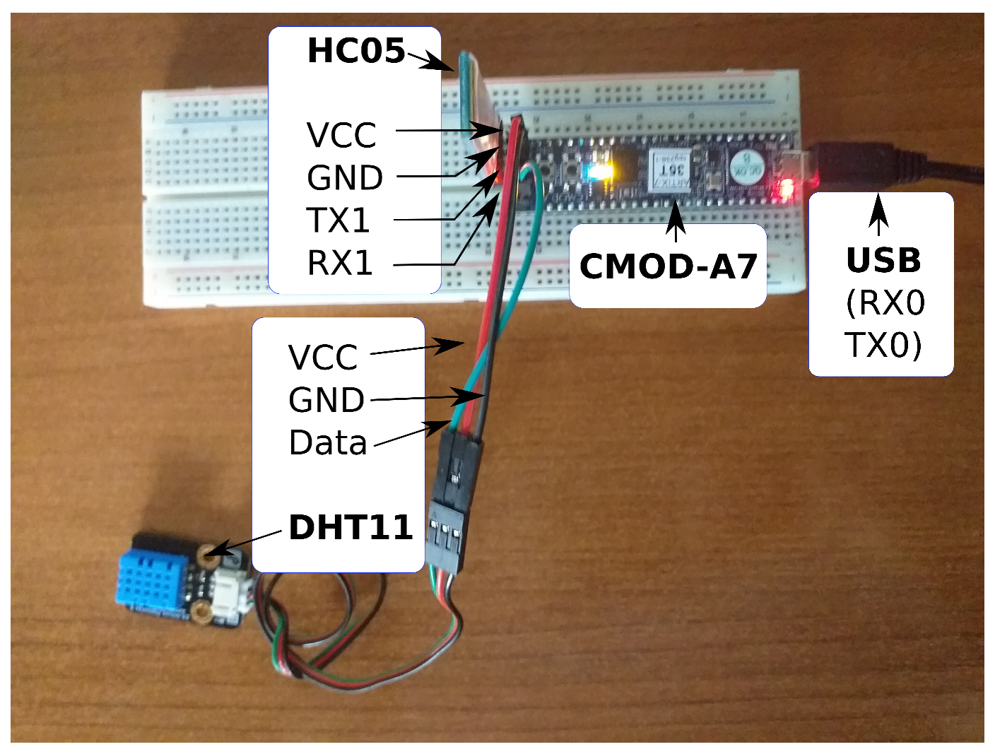
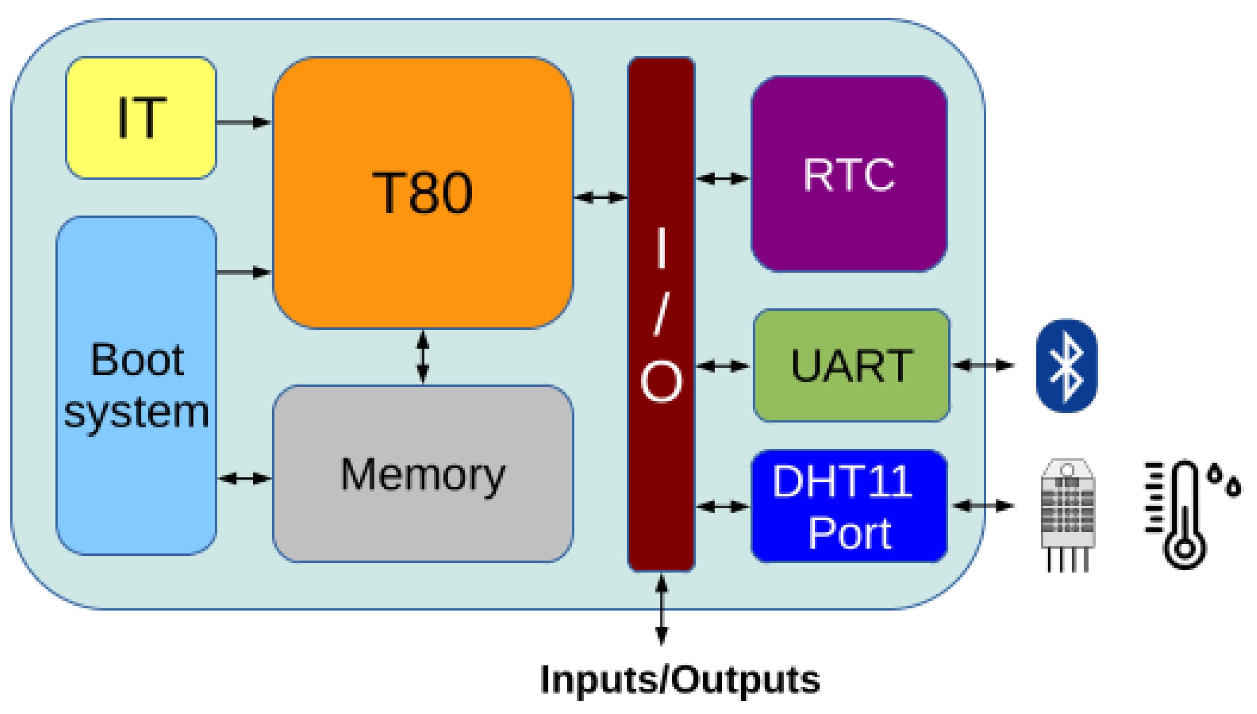
5.1. Bluetooth Humidity/Temperature Wireless Sensor IoT Node
In this first example, the minimal Dracon implementation is extended connecting a Bluetooth HC-05 transceiver [
56] to the UART ports and a DHT11 [
57] humidity/temperature sensor. This sensor is digital and uses a one-wire bidirectional protocol to receive/send information. This requires to include an additional I/O port and to add a small hardware module for adapting the bus signals, as shown in
Figure 10, while implementation results are detailed in
Table 4. An image of the corresponding experimental setup is shown in
Figure 11.
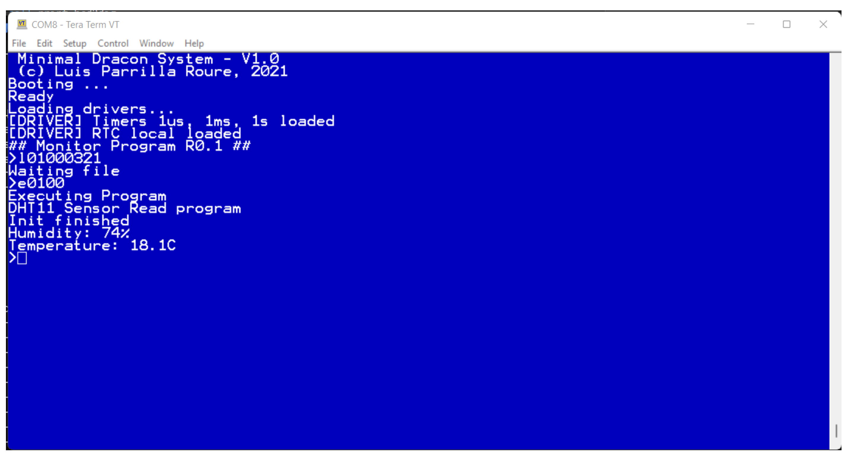
The cost of this extension is only 16 LUTs on Spartan 7 or Artix 7 devices and 49 LUT4s on Lattice MachXO3LF devices, thus, being negligible. Regarding the software to read the information provided by the sensor, it can be loaded using the MP included in the firmware, as shown in
Figure 12. This program is exactly the same for Intel, Xilinx, Lattice or any other FPGA manufacturer. Thus, it is possible to build an IoT sensor device from Dracon with minimal effort and to implement it on low-cost FPGAs.
5.2. Including a Cryptoprocessor to Secure Communications in Dracon
In this application, the flexibility of Dracon to include co-processors and add new features will be shown. Concretely, a cryptographic processor providing Advanced Encryption Standard (AES) [
58] as symmetric cipher to secure communications was implemented in this example. Only the AES128 part of the ECC163AES128 cryptoprocessor from [
59] was connected to the T80 microprocessor using their I/O ports for adding symmetric cryptography support by means of AES-128 ciphers. Using AES, it is possible to encrypt/decrypt communications over insecure channels, such as Bluetooth, using pre-shared keys [
60].
In this case, the implementation results are those shown in
Table 5, the block diagram is presented in
Figure 13 with the cryptographyc core and an additional UART, and the experimental setup is presented in
Figure 14, where UART0 is implemented through a USB connector for debugging purposes and UART1 is connected to an HC-05 bluetooth module [
56].
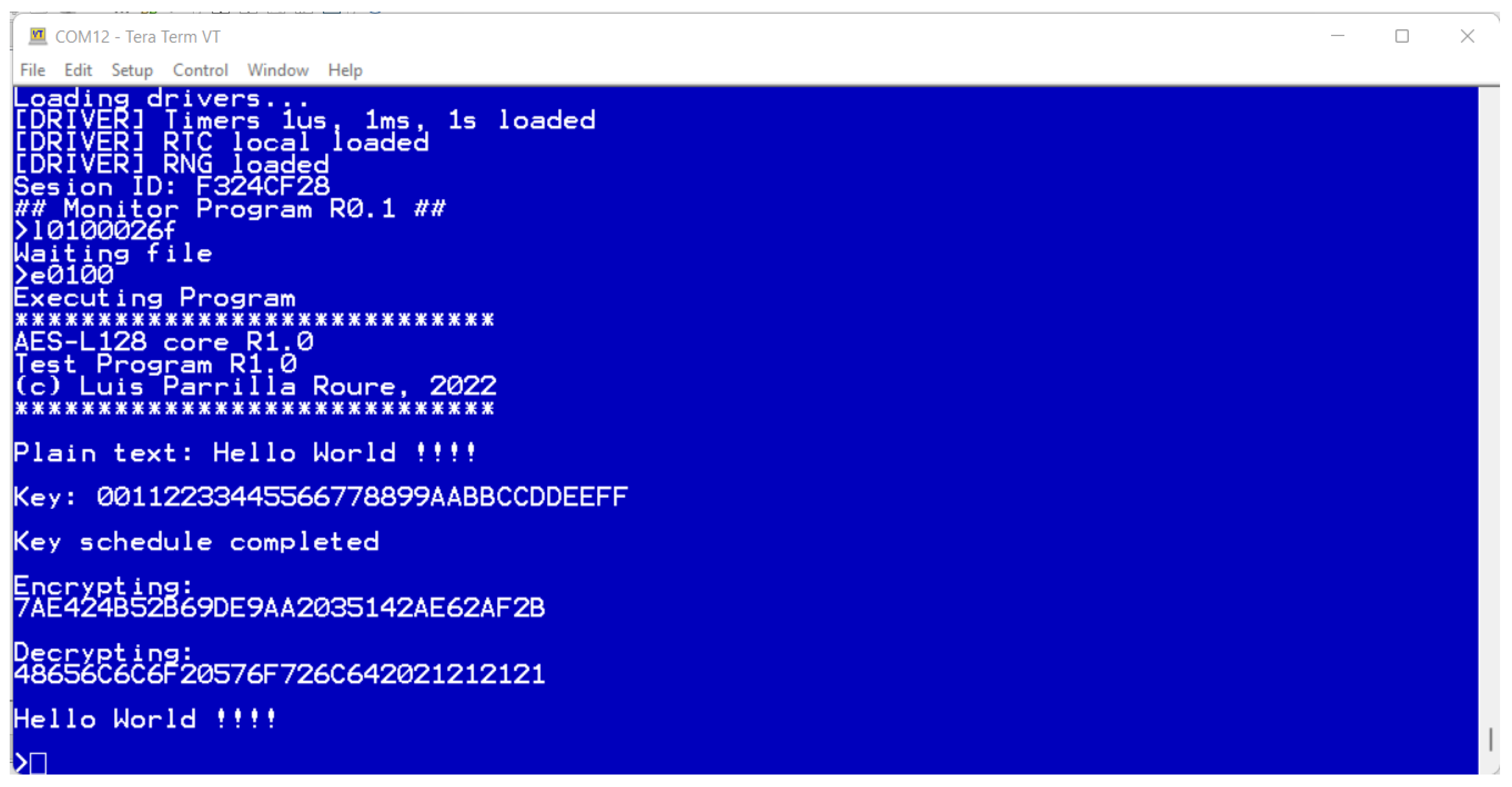
Figure 15 shows execution in Dracon of the test program for encrypting and decrypting information using the AES-128 enabled co-processor.
5.3. Completely Embedded IoT Device in a Single Chip
In the previous examples, software is loaded from the outside using the program loader included in the Monitor Program. This task can be automated from an application executed in a Personal Computer (PC) using Bluetooth communications; however, it is also possible to build a completely embedded application replacing the Program Monitor by the desired specific application while taking advantage of the included firmware calls and functions. All these functionalities will be then stored into the Dracon ROM, thus, using the RAM memory only for data management.
Therefore, Dracon provides a complete solution in a single silicon device, with no need for external memory.
Figure 16 shows the modifications performed in the memory map, where now we have only the ROM, including firmware calls and 4 KB of RAM for data management. Additionally, it is shown how the I/O ports can be easily extended taking advantage of Dracon’s modularity in order to afford the new required modules. With these modifications, a secure IoT sensor device is obtained, which exchanges information, previously encrypted using AES-128 in ECB mode [
61] (but with RTC values as salt to avoid obtaining the same ciphertext when the same data are sent), through Bluetooth.
6. Conclusions and Future Work
We presented a hardware platform to implement one-chip IoT devices with no need for external memory, and this also allows easy and rapid prototyping of co-processors and cores for reconfigurable devices. The platform, named Dracon, includes a T80 (Z80 clone) microprocessor and can support up to 64 KB of RAM and 256 I/Os. When implemented on a Spartan 7 FPGA by Xilinx/AMD, it requires only 1515 LUT6s and five BRAMs and also includes a UART, 4 KB of ROM, 16 KB of RAM, a Real Time Clock and an Interrupt Timer as standard peripherals.
In the case of Intel FPGAs, it requires 2900 LEs and 163840 bits of memory on Cyclone IV devices and only 1210 ALMs with the same memory when implemented on Cyclone V devices. Minimal Dracon has also been implemented on MAchXO3LF devices from Lattice, requiring 2983 LUT4s and 20 EBRs. These results show that Dracon can be easily implemented on low-cost FPGAs, while also illustrating its ability to be implemented on devices from different vendors. A software tool-chain was also proposed, using the cross assembler tniASM [
31], for software development, along with specific tools developed by the authors to generate a VHDL description of a ROM, including the firmware.
Application examples show the flexibility and the ease to adapt Dracon to prototype a given IoT application. The Dracon minimal implementation is available for download, and it can be freely used to develop and test complex IoT applications on low-cost FPGAs. The use of an open-source soft-core 8-bit microprocessor enables the implementation of complex applications with no need for external memory on low-cost FPGAs, thus, presenting a clear advantage when compared to other private and open-hardware platforms, such as those based on 32-bit RISC-V processors. Moreover, software that is developed for Dracon can be implemented without changes on FPGAs from different vendors.
As a proof of concept of all features provided by Dracon, three application examples were performed. In the first one, we detailed how to build a Bluetooth humidity/temperature wireless sensor IoT node on top of mDracon with minimal modifications and area cost. In the second example, a new UART and an additional cryptographic processor were added to build a secure IoT sensor node, thus, demonstrating the modularity and flexibility of Dracon. The last example makes use of this flexibility to build a completely embedded and standalone IoT application, all of it included in the internal ROM of the device and taking advantage of software calls provided by Dracon firmware.
As future work, we are working on the development of a GUI-based software tool to make it easier for final users to incorporate modules into Dracon without the direct editing of VHDL files. Furthermore, firmware versions that include floating point arithmetic are being developed to extend the edge computing capabilities. Additionally, we are approaching the development of different drivers for WiFi, Zigbee and LoRa modules, in order to extend the integration of Dracon into different IoT networks.
Author Contributions
Conceptualization, L.P., A.G., E.C., J.A.Á.-B., J.A.L.-V. and U.M.-B.; methodology, L.P.; software, L.P.; validation, L.P., A.G., E.C., J.A.Á.-B., J.A.L.-V. and U.M.-B.; formal analysis, L.P. and A.G.; investigation, L.P., A.G. and E.C.; resources, L.P. and E.C.; data curation, L.P. and A.G.; writing—original draft preparation, L.P. and A.G.; writing—review and editing, L.P., A.G., E.C., J.A.Á.-B., J.A.L.-V. and U.M.-B.; visualization, L.P. and E.C.; supervision, L.P.; project administration, L.P.; funding acquisition, L.P. and E.C. All authors have read and agreed to the published version of the manuscript.
Funding
This work was partially supported by the Consejería de Economía y Conocimiento de la Junta de Andalucía (Spain) and by the European Regional Development Funds (ERDF) under Project B-TIC-588-UGR20.
Data Availability Statement
Not applicable.
Conflicts of Interest
The authors declare no conflict of interest.
References
- Shafique, K.; Khawaja, B.A.; Sabir, F.; Qazi, S.; Mustaqim, M. Internet of things (IoT) for next-generation smart systems: A review of current challenges, future trends and prospects for emerging 5G-IoT scenarios. IEEE Access 2020, 8, 23022–23040. [Google Scholar] [CrossRef]
- Tawalbeh, L.; Muheidat, F.; Tawalbeh, M.; Quwaider, M. IoT Privacy and security: Challenges and solutions. Appl. Sci. 2020, 10, 4102. [Google Scholar] [CrossRef]
- Farahani, B.; Firouzi, F.; Luecking, M. The convergence of IoT and distributed ledger technologies (DLT): Opportunities, challenges, and solutions. J. Netw. Comput. Appl. 2021, 177, 102936. [Google Scholar] [CrossRef]
- Bruschi, N.; Haugou, G.; Tagliavini, G.; Conti, F.; Benini, L.; Rossi, D. GVSoC: A Highly Configurable, Fast and Accurate Full-Platform Simulator for RISC-V based IoT Processors. In Proceedings of the 2021 IEEE 39th International Conference on Computer Design (ICCD), Storrs, CT, USA, 24–27 October 2021; IEEE: Piscataway, NJ, USA, 2021; pp. 409–416. [Google Scholar]
- Magyari, A.; Chen, Y. FPGA Remote Laboratory Using IoT Approaches. Electronics 2021, 10, 2229. [Google Scholar] [CrossRef]
- Guo, X. Application of agricultural IoT technology based on 5 G network and FPGA. Microprocess Microsyst. 2021, 80, 103597. [Google Scholar] [CrossRef]
- Babiuch, M.; Foltỳnek, P.; Smutnỳ, P. Using the ESP32 microcontroller for data processing. In Proceedings of the 2019 20th International Carpathian Control Conference (ICCC), Wieliczka, Poland, 26–29 May 2019; IEEE: Piscataway, NJ, USA, 2019; pp. 1–6. [Google Scholar]
- Krasteva, Y.E.; Portilla, J.; de la Torre, E.; Riesgo, T. Embedded runtime reconfigurable nodes for wireless sensor networks applications. IEEE Sens. J. 2011, 11, 1800–1810. [Google Scholar] [CrossRef]
- Intel. Nios II Processor Reference Guide. Available online: https://www.altera.com/content/dam/altera-www/global/en_US/pdfs/literature/hb/nios2/n2cpu-nii5v1gen2.pdf (accessed on 1 March 2022).
- Sehatbakhsh, N.; Alam, M.; Nazari, A.; Zajic, A.; Prvulovic, M. Syndrome: Spectral analysis for anomaly detection on medical iot and embedded devices. In Proceedings of the 2018 IEEE International Symposium on Hardware Oriented Security and Trust (HOST), Washington, DC, USA, 30 April 30–4 May 2018; IEEE: Piscataway, NJ, USA, 2018; pp. 1–8. [Google Scholar]
- Arora, J.; Pandya, U.; Shah, S.; Doshi, N. Survey-pollution monitoring using IoT. Procedia Comput. Sci. 2019, 155, 710–715. [Google Scholar] [CrossRef]
- Xilinx Inc. MicroBlaze Processor Reference Guide. Available online: https://www.xilinx.com/support/documentation/sw_manuals/xilinx2018_1/ug984-vivado-microblaze-ref.pdf (accessed on 1 March 2022).
- Kim, H.Y.; Xu, L.; Shi, W.; Suh, T. A secure and flexible FPGA-based blockchain system for the IIoT. Computer 2021, 54, 50–59. [Google Scholar] [CrossRef]
- Wang, Z.x.; Sha, K.y.; Gao, X.l. Digital Image Encryption Test System Based on FPGA and Nios II Soft Core. Autom. Control Comput. Sci. 2021, 55, 490–499. [Google Scholar] [CrossRef]
- Skliarova, I. Accelerating Population Count with a Hardware Co-Processor for MicroBlaze. J. Low Power Electron. Appl. 2021, 11, 20. [Google Scholar] [CrossRef]
- Kranenburg, T.; Van Leuken, R. MB-LITE: A robust, light-weight soft-core implementation of the MicroBlaze architecture. In Proceedings of the 2010 Design, Automation & Test in Europe Conference & Exhibition (DATE 2010), Dresden, Germany, 8–12 March 2010; IEEE: Piscataway, NJ, USA, 2010; pp. 997–1000. [Google Scholar]
- Liu, J.; Feng, J. Design of embedded digital image processing system based on ZYNQ. Microprocess Microsyst. 2021, 83, 104005. [Google Scholar] [CrossRef]
- Ma, L.; Sham, C.W. Soc-fpga-based implementation of iris recognition enhanced by qc-ldpc codes. In Proceedings of the 2019 International Conference on Field-Programmable Technology (ICFPT), Tianjin, China, 9–13 December 2019; IEEE: Piscataway, NJ, USA, 2019; pp. 391–394. [Google Scholar]
- Meyer-Baese, U. Embedded Microprocessor System Design Using FPGAs; Springer: Berlin/Heidelberg, Germany, 2021. [Google Scholar]
- Gaisler, C. LEON3 Processor. Available online: http://www.gaisler.com/index.php/products/processors/leon3 (accessed on 1 March 2022).
- Waterman, A.S. Design of the RISC-V Instruction Set Architecture; University of California: Berkeley, CA, USA, 2016. [Google Scholar]
- Matthews, E.; Shannon, L. TAIGA: A new RISC-V soft-processor framework enabling high performance CPU architectural features. In Proceedings of the 2017 27th International Conference on Field Programmable Logic and Applications (FPL), Ghent, Belgium, 4–8 September 2017; IEEE: Piscataway, NJ, USA, 2017; pp. 1–4. [Google Scholar]
- Seol, H.; Kim, M.; Kim, T.; Kim, Y.; Kim, L.S. Amnesiac DRAM: A proactive defense mechanism against cold boot attacks. IEEE Trans. Comput. 2019, 70, 539–551. [Google Scholar] [CrossRef]
- Guan, L.; Cao, C.; Zhu, S.; Lin, J.; Liu, P.; Xia, Y.; Luo, B. Protecting mobile devices from physical memory attacks with targeted encryption. In Proceedings of the 12th Conference on Security and Privacy in Wireless and Mobile Networks, Miami, FL, USA, 15–17 May 2019; pp. 34–44. [Google Scholar]
- Zuo, P.; Hua, Y.; Liang, L.; Xie, X.; Hu, X.; Xie, Y. SEALing Neural Network Models in Encrypted Deep Learning Accelerators. In Proceedings of the 2021 58th ACM/IEEE Design Automation Conference (DAC), San Francisco, CA, USA, 5–9 December 2021; IEEE: Piscataway, NJ, USA, 2021; pp. 1255–1260. [Google Scholar]
- Warner, D. T80 cpu. Available online: https://opencores.org/project/t80/overview (accessed on 1 March 2022).
- Zilog Corp. Z80 CPU User Manual. Available online: www.zilog.com/manage_directlink.php?filepath=docs/z80/um0080&extn=.pdf (accessed on 1 March 2022).
- FPGA Arcade Project. The Replay Board. Available online: www.fpgaarcade.com (accessed on 1 March 2022).
- Etcheverry, L.; Oliver, J.; Acle, J.P. A soft-core based lab for an introductory microprocessors course. In Proceedings of the 2012 Technologies Applied to Electronics Teaching (TAEE), Vigo, Spain, 13–15 June 2012; IEEE: Piscataway, NJ, USA, 2012; pp. 72–76. [Google Scholar]
- Digital Research. CP/M. Available online: http://www.digitalresearch.biz/CPM.HTM (accessed on 1 March 2022).
- TNI. tniASM Macro Assembler. Available online: http://www.tni.nl/products/tniasm.html (accessed on 1 March 2022).
- SDCC. SDCC-Small Device C Compiler. Available online: http://sdcc.sourceforge.net/ (accessed on 1 March 2022).
- Moore, J. ZEMU-Z80 Emulator. Available online: http://www.shaels.net/index.php/z80emu/z80emu-downloads (accessed on 1 March 2022).
- Preethichandra, D. Z80—The 1970s Microprocessor Still Alive. IEEE Micro 2021, 41, 156–157. [Google Scholar] [CrossRef]
- Meyer-Baese, U. Design of the P ico B laze Softcore Microprocessor. In Embedded Microprocessor System Design Using FPGAs; Springer: Berlin/Heidelberg, Germany, 2021; pp. 227–251. [Google Scholar]
- Uffenbeck, J. Microcomputers and Microprocessors: The 8080, 8085, and Z-80 Programming, Interfacing, and Troubleshooting; Prentice-Hall, Inc.: Hoboken, NJ, USA, 1991. [Google Scholar]
- Chapman, K. PicoBlaze for Spartan-6, Virtex-6, 7-Series, Zynq and UltraScale Devices (KCPSM6), Xilinx Application Note. 2014. Available online: http://www-classes.usc.edu/engr/ee-s/254/ee254l_lab_manual/PicoBlaze/Picoblaze_KCPSM6_Release9_30Sept14/READ_ME_FIRST.txt (accessed on 22 May 2022).
- Xilinx Inc. 7 Series FPGAs Family Overview. Available online: https://docs.xilinx.com/v/u/en-US/ds180_7Series_Overview (accessed on 18 April 2022).
- Altera. Ciclone V device Handbook. Available online: https://www.intel.com/content/dam/www/programmable/us/en/pdfs/literature/hb/cyclone-v/cv_52006.pdf (accessed on 18 April 2022).
- Altera. Ciclone IV Device Handbook. Available online: https://www.intel.com/content/dam/www/programmable/us/en/pdfs/literature/hb/cyclone-iv/cyclone4-handbook.pdf (accessed on 18 April 2022).
- Lattice Semiconductors. MachXO3 Family Data Sheet. Available online: https://www.latticesemi.com/view_document?document_id=50121 (accessed on 18 April 2022).
- Intel. Intel Quartus Prime Standard Edition Version 21.1 Software and Device Support Release Notes. Available online: https://www.intel.com/content/www/us/en/docs/programmable/683593/21-1/version-software-and-device-support-53221.html (accessed on 1 March 2022).
- Xilinx Inc. Vivado 2020.2 Vivado Design Suite User Guide. Release Notes, Installation, and Licensing. Available online: https://www.xilinx.com/content/dam/xilinx/support/documents/sw_manuals/xilinx2020_2/ug973-vivado-release-notes-install-license.pdf (accessed on 1 March 2022).
- Lattice Semiconductors. Lattice Diamond Software 3.12 Release Notes. Available online: https://www.latticesemi.com/-/media/LatticeSemi/Documents/Diamond312/Diamond_312_release-notes.ashx?document_id=53073 (accessed on 1 March 2022).
- Scherrer, T. Z80 Info Page. Available online: http://www.z80.info (accessed on 18 April 2022).
- DCD. Digital Core Design. Available online: https://www.dcd.pl/ (accessed on 1 March 2022).
- Raghunathan, K.R. History of Microcontrollers: First 50 Years. IEEE Micro 2021, 41, 97–104. [Google Scholar] [CrossRef]
- Kamaluddin, M.U.; Shahbudin, S.; Isa, N.M.; Abidin, H.Z. Teaching the Intel 8051 Microcontroller with hands-on hardware experiments. In Proceedings of the 2015 IEEE seventh International Conference on Engineering Education (ICEED), Kanazawa, Japan, 17–18 November 2015; IEEE: Piscataway, NJ, USA, 2015; pp. 100–105. [Google Scholar]
- Wilmshurst, T. Designing Embedded Systems with PIC Microcontrollers: Principles and Applications; Elsevier: Amsterdam, The Netherlands, 2006. [Google Scholar]
- Xilinx Inc. 7 Series FPGAs Memory Resources User Guide. Available online: https://docs.xilinx.com/v/u/en-US/ug473_7Series_Memory_Resources (accessed on 18 April 2022).
- Lattice Semiconductors. Memory Usage Guide for MachXO3 Devices. Available online: https://www.latticesemi.com/view_document?document_id=50515 (accessed on 18 April 2022).
- Digilent Inc. Cmod S7. Available online: https://digilent.com/reference/programmable-logic/cmod-s7/start (accessed on 18 April 2022).
- Parrilla, L. mDracon for CMOD-S7 Board Configuration File. Available online: https://ditec.ugr.es/sites/default/files/descargas/mDracon/top_mdracon_S7.bit (accessed on 18 April 2022).
- Parrilla, L. Hello World for Dracon. Available online: https://ditec.ugr.es/sites/default/files/descargas/mDracon/hello2.bin (accessed on 18 April 2022).
- Saini, R.; Mussbacher, G. Towards Conflict-Free Collaborative Modelling using VS Code Extensions. In Proceedings of the 2021 ACM/IEEE International Conference on Model Driven Engineering Languages and Systems Companion (MODELS-C), Fukuoka, Japan, 10–15 October 2021; IEEE: Piscataway, NJ, USA, 2021; pp. 35–44. [Google Scholar]
- Singh, V.K.; Sahu, A.; Beg, A.; Khan, B.; Kumar, S. Speed & direction control of DC motor through Bluetooth HC-05 using Arduino. In Proceedings of the 2018 International Conference on Advanced Computation and Telecommunication (ICACAT), Bhopal, India, 28–29 December 2018; IEEE: Piscataway, NJ, USA, 2018; pp. 1–3. [Google Scholar]
- Sharmila, F.M.; Suryaganesh, P.; Abishek, M.; Benny, U. IoT based smart window using sensor Dht11. In Proceedings of the 2019 fifth International Conference on Advanced Computing & Communication Systems (ICACCS), Coimbatore, India, 15–16 March 2019; IEEE: Piscataway, NJ, USA, 2019; pp. 782–784. [Google Scholar]
- Mouha, N.; Dworkin, M. Review of the Advanced Encryption Standard. In NIST Interagency/Internal Report (NISTIR); National Institute of Standards: Gaithersburg, MD, USA, 2021. [Google Scholar]
- Parrilla, L.; Castillo, E.; López-Ramos, J.A.; Álvarez-Bermejo, J.A.; García, A.; Morales, D.P. Unified compact ECC-AES co-processor with group-key support for IoT devices in wireless sensor networks. Sensors 2018, 18, 251. [Google Scholar] [CrossRef] [PubMed] [Green Version]
- Harn, L.; Hsu, C.; Xia, Z. Lightweight group key distribution schemes based on pre-shared pairwise keys. IET Commun. 2020, 14, 2162–2165. [Google Scholar] [CrossRef]
- Almuhammadi, S.; Al-Hejri, I. A comparative analysis of AES common modes of operation. In Proceedings of the 2017 IEEE 30th Canadian conference on electrical and computer engineering (CCECE), Windsor, ON, Canada, 30 April–3 May 2017; IEEE: Piscataway, NJ, USA, 2017; pp. 1–4. [Google Scholar]
Figure 1.
Dracon block diagram.
Figure 1.
Dracon block diagram.
Figure 4.
Dracon memory map.
Figure 4.
Dracon memory map.
Figure 6.
pout4bi pinout.
Figure 6.
pout4bi pinout.
Figure 7.
Minimal Dracon block diagram.
Figure 7.
Minimal Dracon block diagram.
Figure 8.
Hello World on Dracon.
Figure 8.
Hello World on Dracon.
Figure 9.
Flow of the Dracon toolchain for (a) compiling and executing applications and (b) firmware and/or embedded applications.
Figure 9.
Flow of the Dracon toolchain for (a) compiling and executing applications and (b) firmware and/or embedded applications.
Figure 10.
Minimal Dracon extended with Bluetooth wireless connectivity and digital humidity/temperature sensor.
Figure 10.
Minimal Dracon extended with Bluetooth wireless connectivity and digital humidity/temperature sensor.
Figure 11.
Experimental setup for minimal Dracon extended with Bluetooth connectivity and measurements with a DHT11 sensor.
Figure 11.
Experimental setup for minimal Dracon extended with Bluetooth connectivity and measurements with a DHT11 sensor.
Figure 12.
Bluetooth humidity/temperature measurement in Dracon.
Figure 12.
Bluetooth humidity/temperature measurement in Dracon.
Figure 13.
Minimal Dracon extended with two UARTs, Bluetooth connectivity and cryptographic support.
Figure 13.
Minimal Dracon extended with two UARTs, Bluetooth connectivity and cryptographic support.
Figure 14.
Experimental setup for minimal Dracon extended with two UARTs, Bluetooth connectivity and cryptographic support for secure measurements with a DHT11 sensor.
Figure 14.
Experimental setup for minimal Dracon extended with two UARTs, Bluetooth connectivity and cryptographic support for secure measurements with a DHT11 sensor.
Figure 15.
AES co-processor Dracon test program execution.
Figure 15.
AES co-processor Dracon test program execution.
Figure 16.
Dracon for building a completely embedded IoT device with hardware AES support.
Figure 16.
Dracon for building a completely embedded IoT device with hardware AES support.
Table 1.
T80a implementation results.
Table 1.
T80a implementation results.
| FPGA Type | Device | #LUTS | Freq. (MHz) |
|---|
| Spartan 7 | XC7S25-LCSGA225C | 1226 LUT6 | 80 |
| Artix 7 | XC7A35T-CPG236-1 | 1220 LUT6 | 80 |
| Cyclone IV | EP4CE22F17C6N | 2335 LE | 84 |
| Cyclone V | 5CEBA2F17A7 | 951 ALM | 84 |
| MachXO3LF | LCMXO3LF-9400C-5BG256C | 2250 LUT4 | 33 |
Table 2.
FPGA 8-bitter implementation results.
Table 2.
FPGA 8-bitter implementation results.
| Name | Device | # LUTS | BRAM | Freq. (MHz) | Vendor |
|---|
| DF6811CPU | Stratix-7 | 2220 LE | 4 | 73 | DCD |
| DF6811CPU | Spartan-III-5 | 2634 LUT4 | N/A | 73 | DCD |
| DR8051 | Cyclone-II-6 | 2250 LE | N/A | 93 | DCD |
| DP8051 | Spartan-III-5 | 2200 LUT4 | N/A | 73 | DCD |
| DFPIC1655X | Cyclone-II-6 | 663 LE | N/A | 91 | DCD |
| DFPIC1655X | Spartan-III-5 | 772 LUT4 | 3 | 52 | DCD |
| PICOBLAZE | Spartan-III | 192 LUT4 | 1 | 88 | Xilinx |
Table 3.
Minimal Dracon implementation results (25-MHz operation).
Table 3.
Minimal Dracon implementation results (25-MHz operation).
| FPGA Type | Device | #LUTS | RAM |
|---|
| Spartan 7 | XC7S25-LCSGA225C | 1515 LUT6 | 5 BRAM |
| Artix 7 | XC7A35T-CPG236-1 | 1512 LUT6 | 5 BRAM |
| Cyclone IV | EP4CE22F17C6N | 2900 LE | 163,840 bits |
| Cyclone V | 5CEBA2F17A7 | 1210 ALM | 163,968 bits |
| MachXO3LF | LCMXO3LF-9400C-5BG256C | 2983 LUT4 | 20 EBRs |
Table 4.
Minimal Dracon with DHT11 sensor support implementation results.
Table 4.
Minimal Dracon with DHT11 sensor support implementation results.
| FPGA Type | Device | #LUTS | RAM |
|---|
| Spartan 7 | XC7S25-LCSGA225C | 1528 LUT6 | 5 BRAM |
| Artix 7 | XC7A35T-CPG236-1 | 1529 LUT6 | 5 BRAM |
| Cyclone IV | EP4CE22F17C6N | 2939 LE | 163,840 bits |
| Cyclone V | 5CEBA2F17A7 | 1256 ALM | 163,968 |
| MachXO3LF | LCMXO3LF-9400C-5BG256C | 3032 LUT4 | 20EBRs |
Table 5.
Minimal Dracon with DHT11 sensor and AES support implementation results.
Table 5.
Minimal Dracon with DHT11 sensor and AES support implementation results.
| FPGA Type | Device | #LUTS | RAM |
|---|
| Spartan 7 | XC7S25-LCSGA225C | 2807 | 13 BRAM |
| Artix 7 | XC7A35T-CPG236-1 | 2800 | 13 BRAM |
| Cyclone IV | EP4CE22F17C6N | 6345 LE | 191,202 bits |
| Cyclone V | 5CEBA2F17A7 | 2681 ALM | 191,386 bits |
| MachXO3LF | LCMXO3LF-9400C-5BG256C | 6236 LUT4 | 48 EBRs |
| Publisher’s Note: MDPI stays neutral with regard to jurisdictional claims in published maps and institutional affiliations. |
© 2022 by the authors. Licensee MDPI, Basel, Switzerland. This article is an open access article distributed under the terms and conditions of the Creative Commons Attribution (CC BY) license (https://creativecommons.org/licenses/by/4.0/).


 ,
, 


