Article

A New Compact Dual-Polarized MIMO Antenna Using Slot and Parasitic Element Decoupling for 5G and WLAN Applications

by
Samuel B. Paiva
1,*,
Adaildo G. D’Assunção Junior
2,
Valdemir P. Silva Neto
1 and
Adaildo Gomes D’Assunção
1
1
Department of Communication Engineering, Federal University of Rio Grande do Norte, P.O. Box 1655, Natal 59078-970, Brazil
2
Federal Institute of Paraíba, João Pessoa 58015-020, Brazil
*
Author to whom correspondence should be addressed.
Electronics 2022, 11(13), 1943; https://doi.org/10.3390/electronics11131943
Submission received: 19 April 2022 / Revised: 29 May 2022 / Accepted: 13 June 2022 / Published: 21 June 2022
(This article belongs to the Special Issue RF/Microwave Circuits for 5G and Beyond)

Abstract

:
This paper presents a compact dual-polarized multiple-input multiple-output (MIMO) antenna for fifth generation (5G) and wireless local area network (WLAN) applications. At first, a compact two-element dual-polarized MIMO antenna designed to operate at 3.5 GHz was developed. After that, some modifications were performed in the initial configuration, and a compact two-element dual-polarized MIMO was designed to operate at 3.5 and 5.35 GHz. A simple decoupling technique using parasitic element and slot was used to enhance the isolation between the radiating elements and to achieve an isolation above 18 dB over the band ranging from 3.4 to 3.6 GHz for the first antenna, and to achieve isolations above 19.8 dB over the first band ranging from 3.4 to 3.6 GHz and above 16.75 dB over the second band ranging from 5.15 to 5.85 GHz for the second antenna. Simulations were performed in the Ansoft HFSS software for numerical characterization and the prototype was fabricated with FR-4 dielectric and measured, presenting a good agreement between simulated and measured results. Furthermore, the envelope correlation coefficient (ECC) and the diversity gain (DG) were analyzed and present good results.

1. Introduction

With the growing evolution of mobile communications technologies, the fifth generation (5G) mobile communication systems have attracted the increasing attention of researchers worldwide in recent years due to several advantages, such as ultra-fast speeds, low latency, excellent reliability [1], large channel capacity, high spectral efficiency, and massive connection density [2,3].
Due to allocation of the C-band frequency spectrum of 3.4–3.6 GHz, i.e., the Long Term Evolution (LTE) band 42, for future 5G wireless communication [4,5], the sub-6 GHz multiple-input multiple-output (MIMO) array antenna design currently has been extensively investigated. The MIMO technology has attracted increasing research both in the industry and academic community [6,7] because it can greatly improve the throughput, capacity, and link reliability of mobile communication systems [8]. Furthermore, because the channel capacity is proportional to the number of antennas used for transmitting and receiving [9], massive MIMO technique, i.e., multiple transmit and receive antennas, has been applied to support big data streams, and also is appointed as a key technique for the 5G. To induce diversity and multiplexing potentials, effective decoupling between the integrated elements is necessary, being a required isolation level above 10 dB for 5G MIMO systems [10]. Nevertheless, to achieve a better performance, a high isolation level, i.e., above 15 dB, has been searched by many researchers, which is a tremendous design challenge [10]. Thus, recently, several types of decoupling techniques have been investigated and applied to achieve a good isolation between the antenna elements.
As 5G wireless communications are multi-network converged systems, the convergence of licensed 5G LTE bands and unlicensed wireless local area network (WLAN) bands can support the increasingly high traffic demand in the heterogeneous networks [6,11]. The allocated bands for 5 GHz unlicensed national information infrastructure (U-NII) can differ from country to country [11,12]. In the United States, the bands of 5.15–5.35 GHz (U-NII-1, U-NII-2A), 5.47–5.725 GHz (UNII-2C), and 5.725–5.85 GHz (U-NII-3) are used for unlicensed wireless access. In Europe and Japan, bands of 5.15–5.35 GHz and 5.47–5.725 GHz are unlicensed for the wireless access system (WAS), including radio local area networks (RLANs). Besides, recently, in Europe, the European Commission proposed allocating the unlicensed WAS/RLAN to use the 5.725–5.85 GHz band. In China, 5.15–5.35 GHz unlicensed band is utilized for indoor environments (i.e., RLAN), whereas 5.725–5.85 GHz band can be used for both indoor and outdoor unlicensed systems [11,12].
Thus, recently, some works on two-element MIMO antennas for 5G and WLAN applications as well for other wireless applications have been reported in the literature [13,14,15,16,17,18,19,20,21,22,23,24]. In [13], an acceptable isolation between the ports of a MIMO antenna designed to operate in the ultra-wideband (UWB) lower-band technology is achieved using a parasitic element and a square slot inserted in the ground plane. In [14], the proposed MIMO antenna for WiMAX/WLAN applications presents isolations above 13 and 16 dB for the two operating bands, respectively, using the defected ground structure (DGS) technique. A dual-band MIMO antenna for telemetry L-band and for mobile communications/long-term evolution band is proposed in [15], where isolation more than 15 dB for both bands is achieved only by considering the close element spacing of 0.26 λ g . The work proposed in [16] presents the design of a dual-band half-elliptic hoof MIMO antenna whose acceptable isolation is achieved by analyzing the TM modes.
In [17], the isolation between ports of a UWB MIMO antenna is greatly increased by etching T-shape slot in the ground plane, achieving a mutual coupling below −16 dB. A reconfigurable MIMO/UWB MIMO antenna with 12.5 dB minimum isolation for cognitive radio applications is proposed in [18]. In [19], the authors developed a dual-band antenna for 5G and C-band applications whose minimum isolation of 15 dB for the two operating bands is achieved. In [20], stubs are introduced in the ground plane of a UWB MIMO antenna to enhance the isolation between the ports, achieving a minimum value of 17 dB. Slots and slits are inserted in the ground plane to improve the isolation of a dual-band MIMO slot antenna for WLAN applications, achieving minimum values of 14 and 12 dB for the first and second operating bands, respectively, in the work proposed by [21]. In [22], the isolation of a high gain MIMO antenna for WLAN applications is enhanced by using parasitic elements and slots in the ground plane, achieving values above 14 and 21 dB for the first and second operating bands, respectively. In [23], two transparent MIMO antennas are proposed for 5G applications and present isolation above 15 dB for both operating bands. A dual-band MIMO antenna with high isolation for 5G and 4G applications is proposed by [24], where a rectangular microstrip stub with defected ground plane is employed to achieve an isolation between ports above 15 dB.
Other works that used slots and parasitic elements to mitigate the mutual coupling between antenna array elements have been recently reported in [25,26]. In [25], a compact high isolation three-sector linear array for point-to-point or point-to-multipoint data communications is proposed, whose high isolation is achieved using parasitic elements that can be used for dual-polarization decoupling. A novel slot-array DGS for decoupling microstrip antenna array is proposed in [26], where the highest isolation is achieved by applying the slot-array DGS when the edge-to-edge spacing between circularly polarized (CP) antenna elements is 0.057 wavelength. In addition, dual-band MIMO antennas with high isolation have been recently reported for 5G/WLAN smartphone applications [27].
In addition, other techniques have also been applied recently to enhance the performance of other antenna parameters, such as gain, for example, using structures such as metasurfaces or frequency selective surface (FSS) single-layer or multi-layer reflectors, as shown in [28]. Furthermore, as shown in [29], artificial intelligence algorithms and fractal geometries have been used to miniaturize and improve antenna impedance matching.
This work proposes a compact dual-band and dual-polarized MIMO two-element antenna for 5G/WLAN applications. The device presents an isolation higher than 19.8 dB over entire LTE 42 band and higher than 16.75 dB over the entire WLAN band (5.15–5.85 GHz), which is achieved by combining parasitic elements and slots etched in the ground plane. Design and simulations are performed in Ansoft HFSS software. To validate the design, the prototype is fabricated and measured, exhibiting a good agreement between simulated and measured results, low mutual coupling between the ports, good impedance matching and desirable values for the envelope correlation coefficient (ECC), and for the diversity gain (DG) for both operating bands.
The critical contribution of this paper is listed in the following:
  • High isolation between the ports using simple and low-cost decoupling techniques such as diagonal slot and parasitic element (above 18 dB for the first proposed antenna and above 19.8 and 16.75 dB for the first and second operating band, respectively, for the second proposed antenna);
  • Overall dimensions of 24 mm × 24 mm for the first proposed antenna and 25 mm × 25 mm for the second proposed antenna, which are compact sizes when compared to the other works available in the literature and cited in this article;
  • Simple, low-cost, ease of manufacturing, dual-band, and dual-polarized performance for 5G and WLAN applications using slots as resonators;
  • New geometries with double L-shaped stub parasitic element decoupling and diagonal slot inserted in the ground plane to improve isolation between the radiating elements.

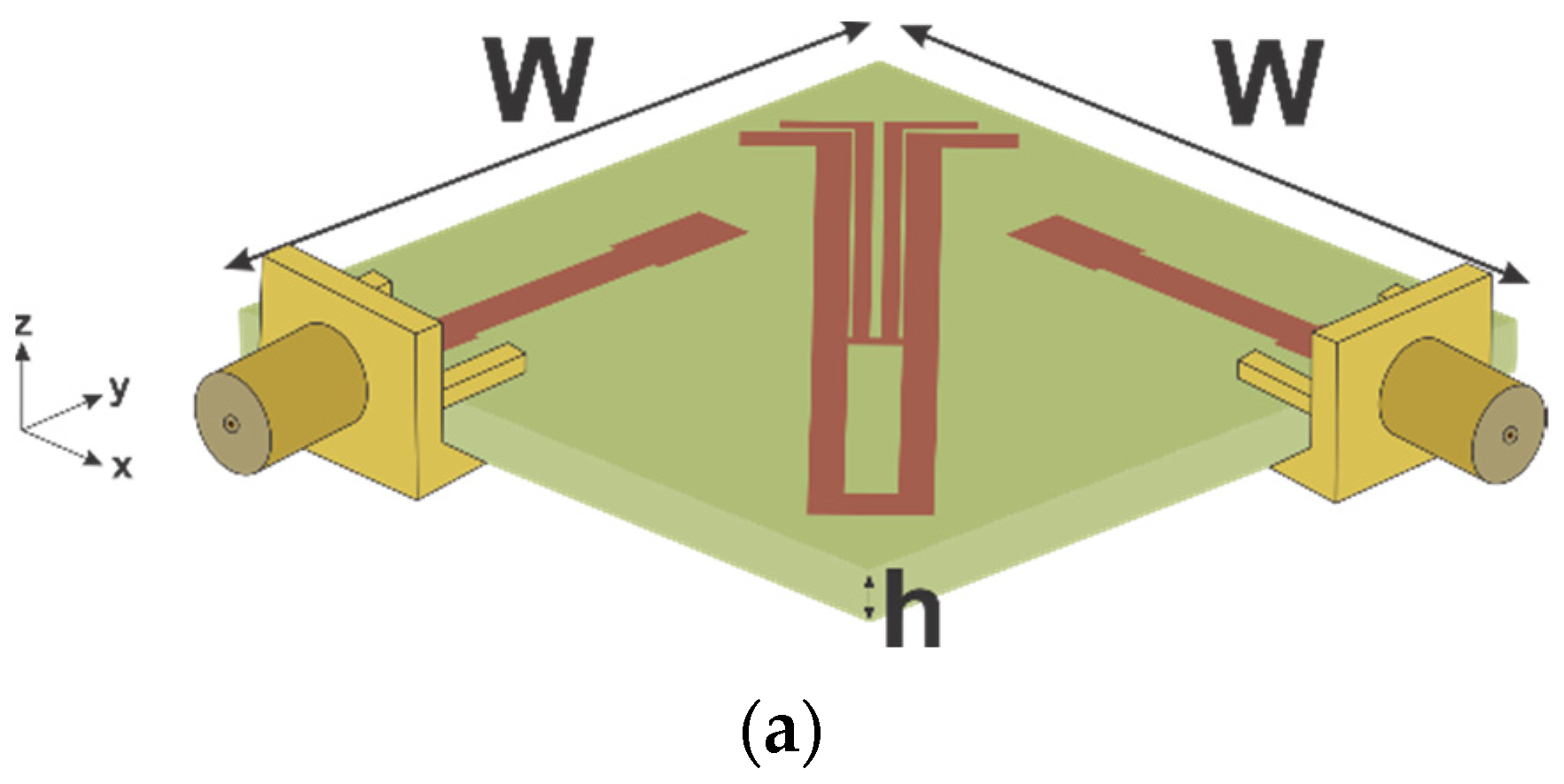
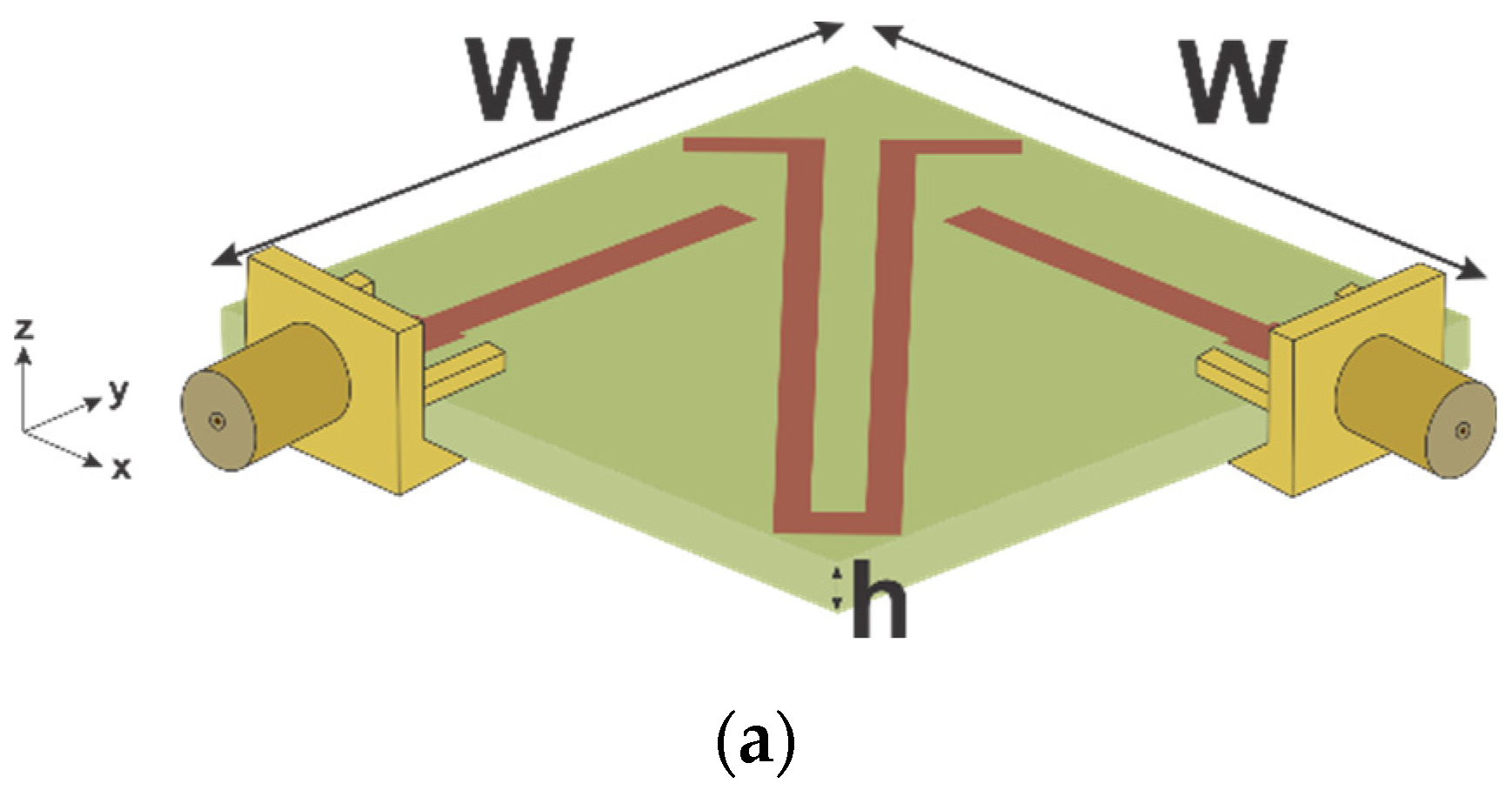
2. Compact MIMO Antenna Design for 5G Applications

The configuration of the first proposed MIMO antenna is presented in Figure 1, whose overall dimensions are 24 mm × 24 mm = 576 mm2. The antenna has been designed on FR-4 substrate ( ε r = 4.4, h = 1.57, t a n δ = 0.02) and is composed of a pair of microstrip lines with step, a parasitic element placed between the pair of microstrip lines with step and three slots etched in the ground plane. The parameter values of the antenna are depicted as follows (in mm): L e = 11.25, L f = 3.5, L p = 26, L p 1 = 3.85, L s = 10.65, L s 1 = 29, W = 24, W f = 2, W l = 1.4, W p = 3.5, W p 1 = 1, W s = 0.5, and W s 1 = 0.5.

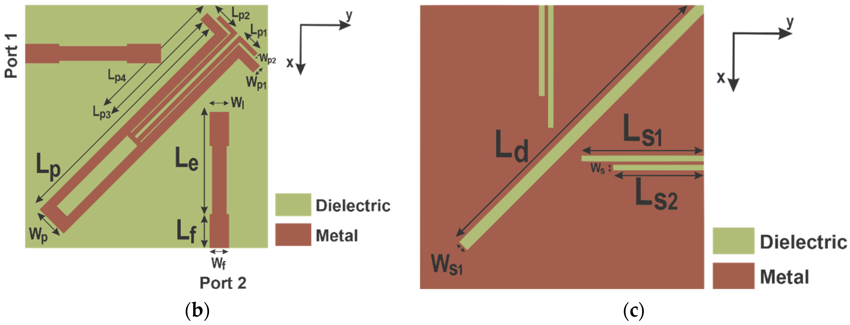
2.1. Slots Design to Achieve the Desired Resonant Frequency

At first, the antenna is designed with only the radiating elements, as shown in Figure 2a,b, whose respective S-parameters values are presented in Figure 2c. As can be observed, the antenna does not work at desired 5G frequency band, exhibiting a bad impedance matching.
Then, to improve the performance, the surface current densities at 3.5 GHz were analyzed for ports 1 and 2 excitations, as illustrated in Figure 3. As can be observed, there are high current densities below the radiating elements on the ground plane. Therefore, slots are etched in these high-density regions of the ground plane for the antenna to operate at the desired frequency, as shown in Figure 4a,b. The slot lengths are optimized up to antenna achieve the resonant frequency of 3.5 GHz, with the values ranging from 9.75 to 10.65 mm. In Figure 4c,d, the S-parameters curves are presented for different values of slot lengths. Furthermore, it is important to note from the surface current densities presented in Figure 3 that for different feeding ports, the current flow contrary to each other will provide the dual-polarization performance [8].
However, although the desired resonance frequency is achieved, the mutual coupling between radiating elements is still high. Thus, it is necessary to apply decoupling techniques to reduce the mutual coupling.

2.2. Decoupling Technique Design

To improve the isolation between the ports, a parasitic element is employed. As can be seen in Figure 1, the parasitic structure consists of two L-shaped stubs, which are connected by a microstrip line between them. At first, to design the L-shaped stubs, it was considered that the length for a L-shaped stub is given by [30]:
L s t   = L x + L y 2 W s t = c 2 f   e e f f
e e f f = e r + 1 2
where, f is the band center frequency, L x , L y , and W s t are the horizontal axis length, the vertical axis length and the microstrip line width, respectively; e e f f is the effective dielectric constant, e r is the relative permittivity, and c is the speed of light. Thus, based on (1) and (2), for a central frequency of 3.5 GHz, the stub length is 26.08 mm. The values of L x , L y , and W s t were optimized and are 25.5 mm, 3.85 mm, and 1 mm, respectively. In addition, the microstrip line placed between the L-shaped stubs has a width of 1.5 mm.
In Figure 5, we investigated the effect caused by the L-shaped stubs in the isolation of the proposed MIMO antenna without changing the ground plane previously shown in Figure 4b. At first, two L-shaped stubs are placed between the radiating elements, as presented in Figure 5a, and the corresponding S-parameters curves are presented in Figure 5b. Thereafter, the two L-shaped stubs are connected by a microstrip line between them, as shown in Figure 5c, achieving the results shown in Figure 5d.

2.3. Ground Plane Design

As can be seen in Figure 6a,b (for ports 1 and 2, respectively), there is a relatively high current density on the ground plane, between the radiating elements. Then, a diagonal slot was etched in that region in the ground plan to improve the isolation, as illustrated in Figure 6c. The diagonal slot lengths are optimized up to achieving a high isolation between the ports, with the values ranging from 25 to 30 mm, as presented in Figure 6d. Furthermore, it is interesting to note in Figure 6e that although the diagonal slot has a considerable influence on the isolation between the two ports, it has very little influence on the antenna operating band.
Therefore, the selected slot length value is 29 mm, because it provides the highest isolation between the ports.

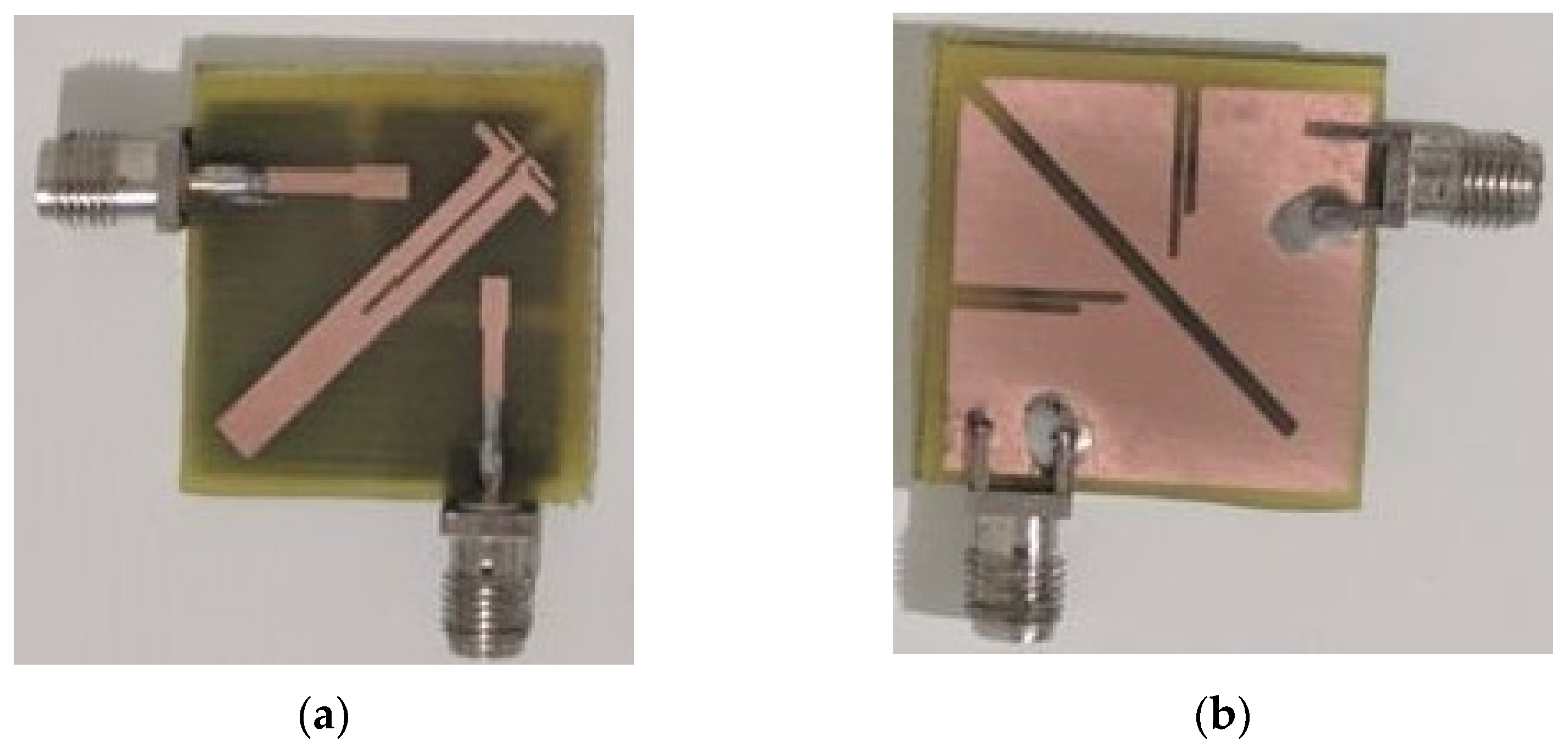
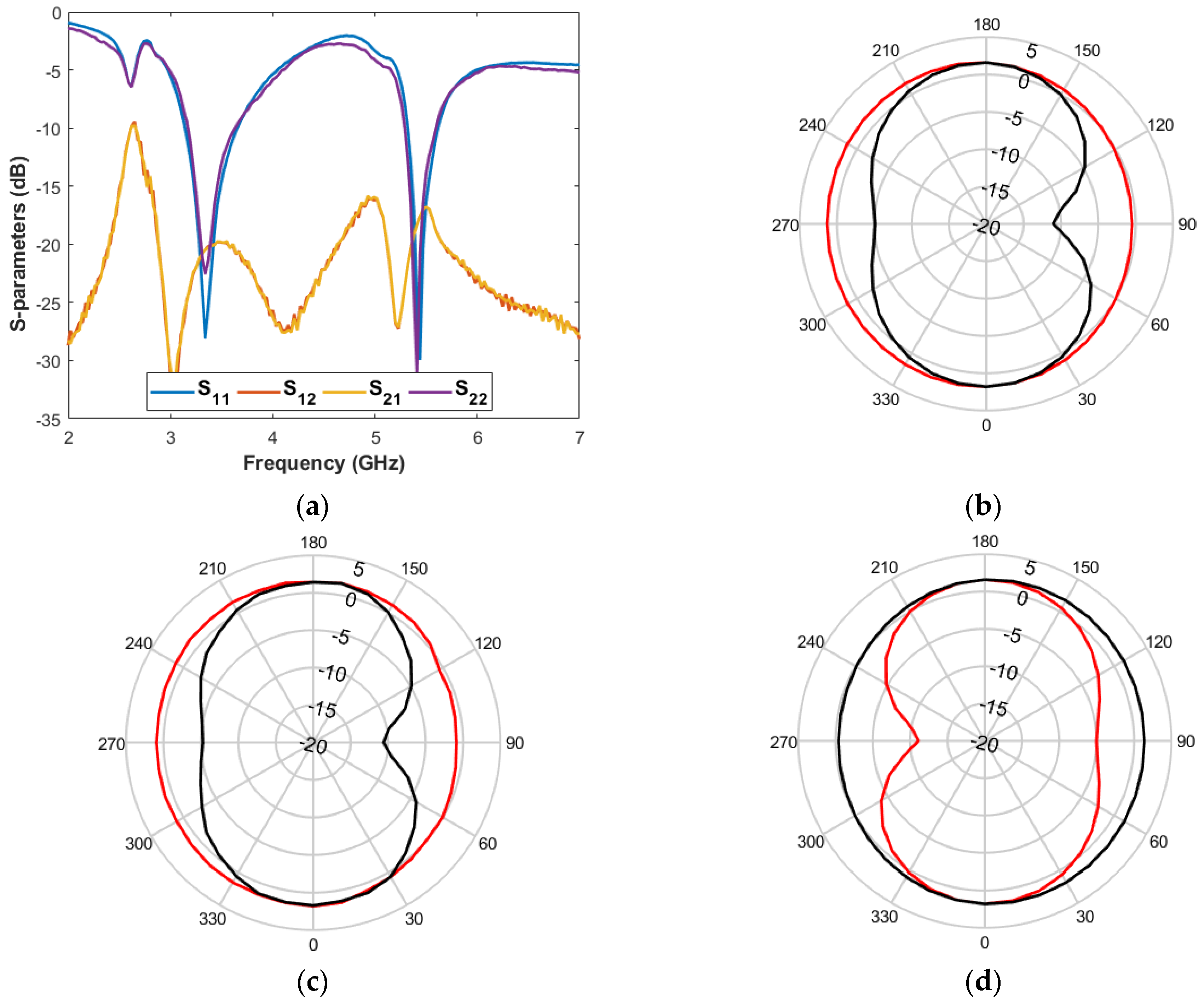
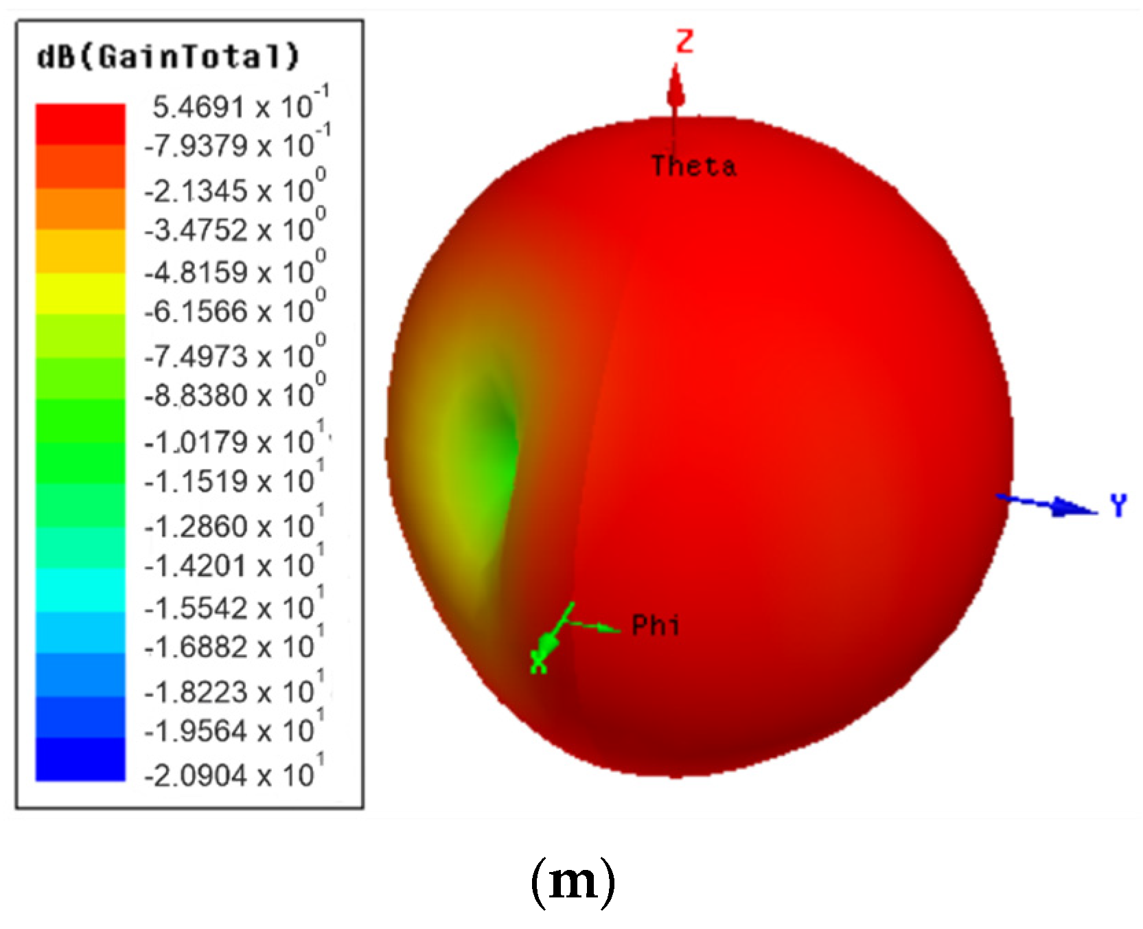
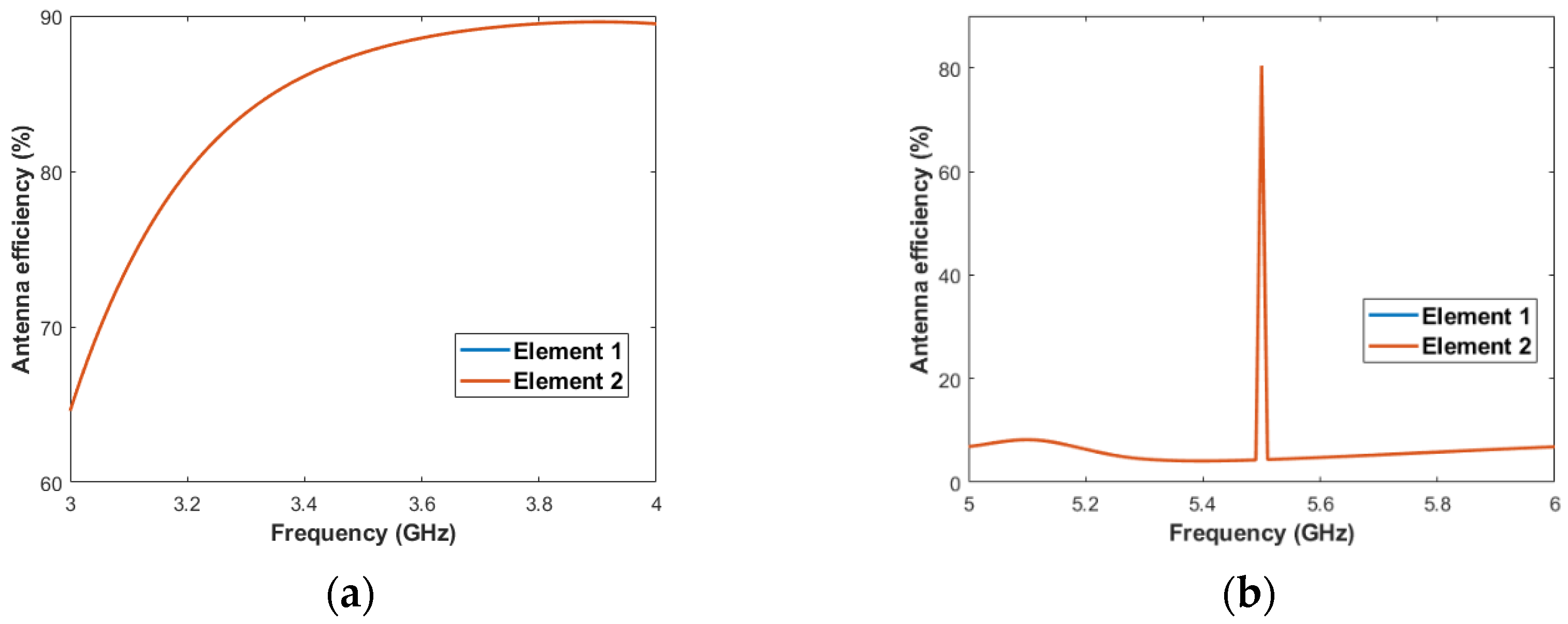
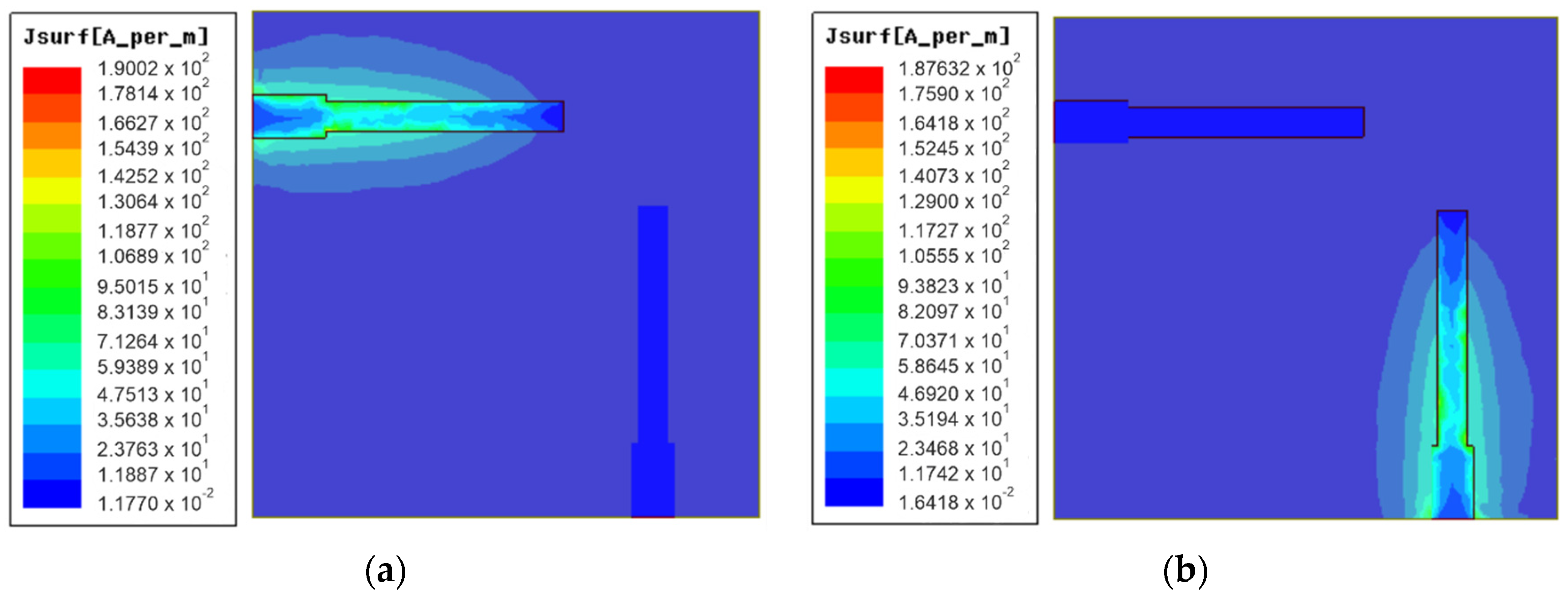
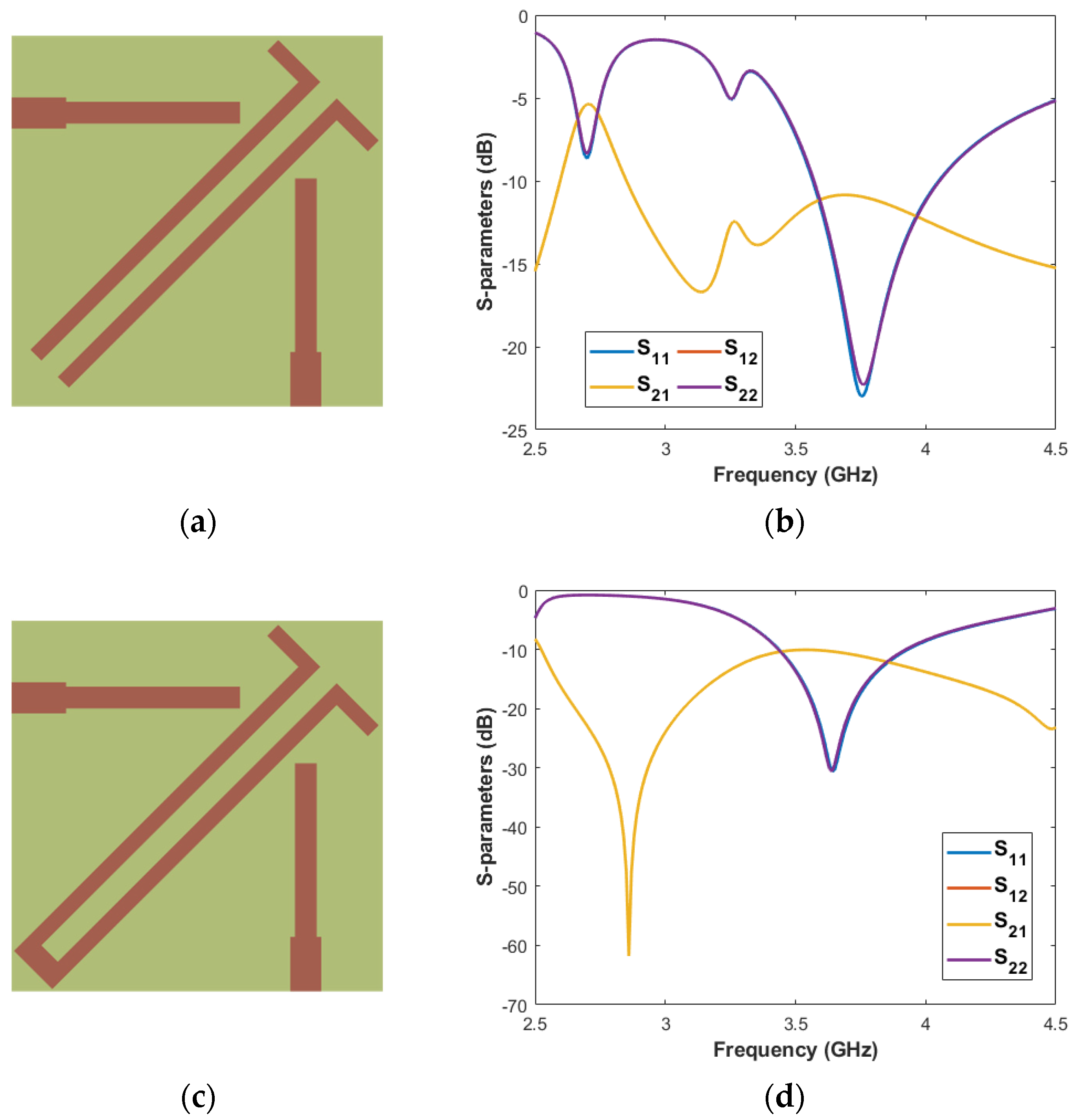
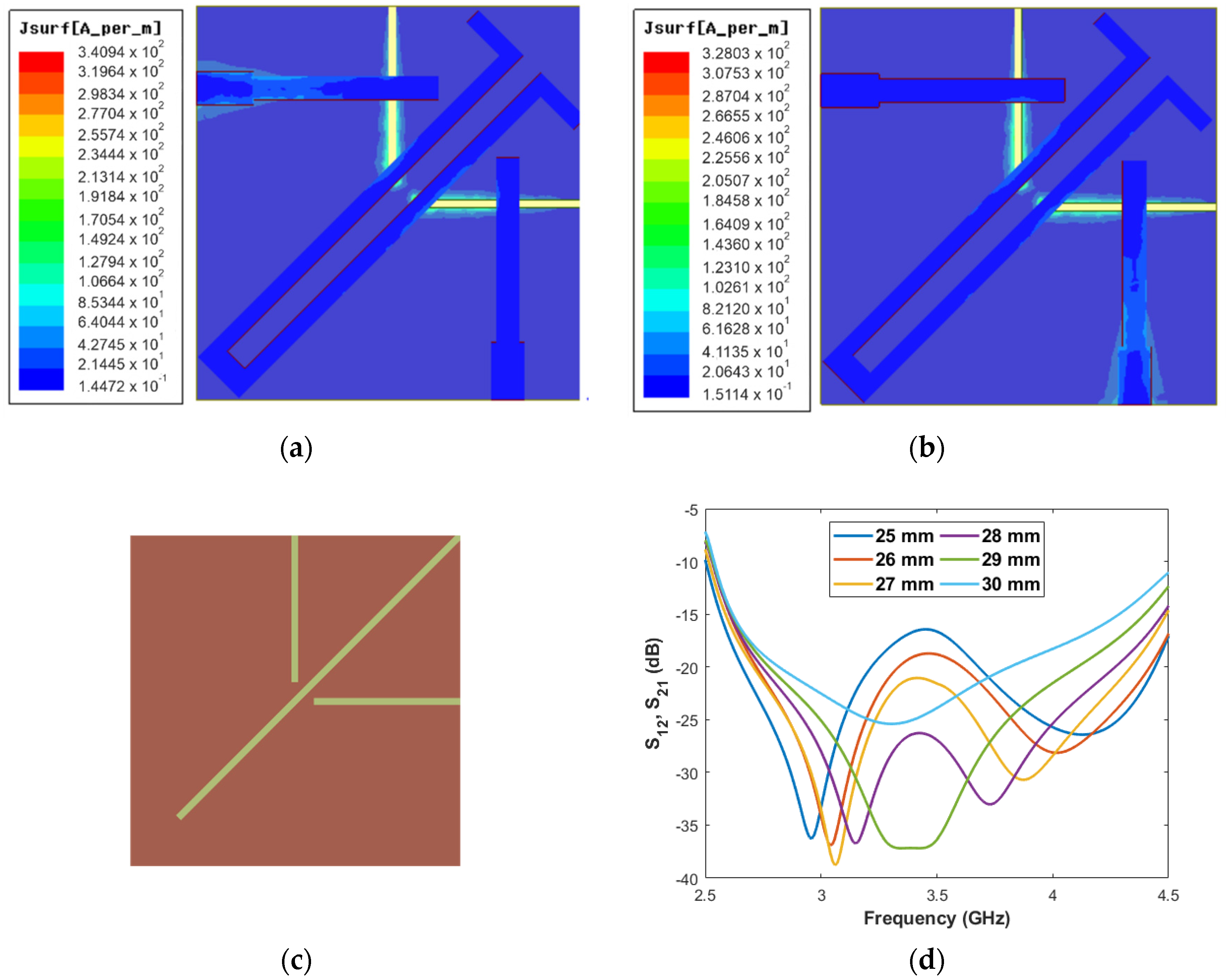
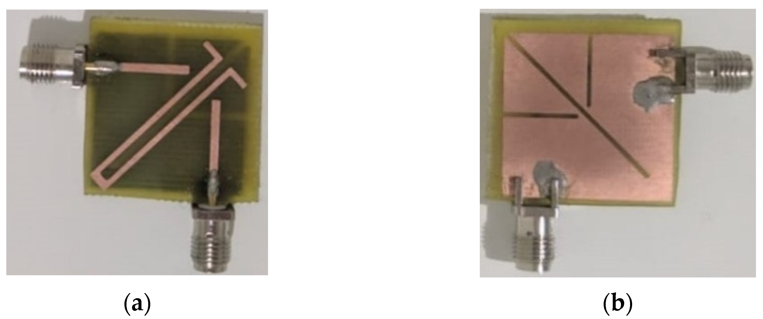
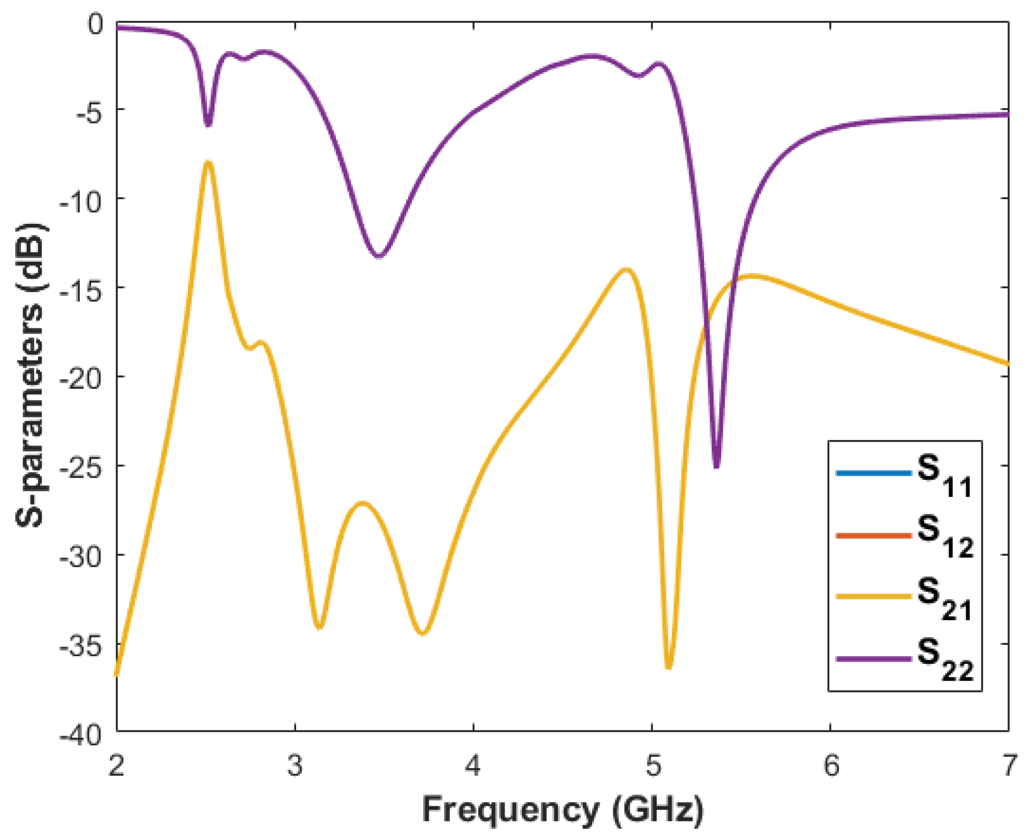
2.4. Antenna Performance

The simulated S-parameters of the MIMO antenna after the application of the decoupling technique to reduce the mutual coupling are shown in Figure 7. The antenna exhibits impedance matching of less than −6 dB over the entire operating band (3.4–3.6 GHz), and high isolations between ports is achieved, with less than −31 dB mutual coupling.
The antenna prototype was fabricated and measured. In Figure 8, the device is shown. An Agilent Technologies E5071C vector network analyzer (VNA) was used to measure the S-parameters values and the 2-D radiation patterns. The measurement setup, the S-parameters, and radiation patterns at 3.5 GHz for ports 1 and 2 are investigated, whose results are presented in Figure 9, which are compared to the simulated results.
As can be observed, a good agreement between the simulated and measured results is obtained. The device provides good impedance matching around 3.5 GHz, and a high isolation, i.e., with more than 18 dB having been achieved.

3. Compact MIMO Antenna Design for 5G/WLAN Applications

In this section, the configuration of the second proposed MIMO antenna is presented. In Figure 10 the antenna configuration is illustrated, whose overall dimensions are 25 mm × 25 mm = 625 mm2. The antenna has been designed on FR-4 substrate ( ε r = 4.4, h = 1.57, t a n δ = 0.02) and is composed of a pair of microstrip lines with step, a parasitic element placed between the pair of microstrip lines with step, and five slots etched in the ground plane. The parameter values of the antenna are depicted as follows (in mm): L e = 10.5, L f = 3.5, W f = 2, L p = 25.5, L p 1 = 2.6, L p 2 = 3.1, L p 3 = 13.29, L p 4 = 15.13, W   = 25, W l = 2, W p = 3.5, W p 1 = 1, W p 1 = 0.5, L d = 30, L s 1 = 10.8, L s 2 = 8, W s = 0.5, and W s 1 = 1.
The design procedure is very similar to that presented in Section 2. Such as in the first design, the surface current densities are analyzed, and to develop the parasitic element used to reduce the mutual coupling between the two ports, the equations (1) and (2) are used. Considering (1) and (2) and central frequencies of 3.5 and 5.35 GHz, the L-shaped stubs lengths for the new design are 26.08 mm and 16.91 mm, respectively. The values of L x , L y , and W s t are optimized and defined as 25 mm, 3.1 mm, and 1 mm, respectively, for 3.5 GHz, and 15 mm, 2.6 mm, and 0.5 mm, respectively, for 5.35 GHz.

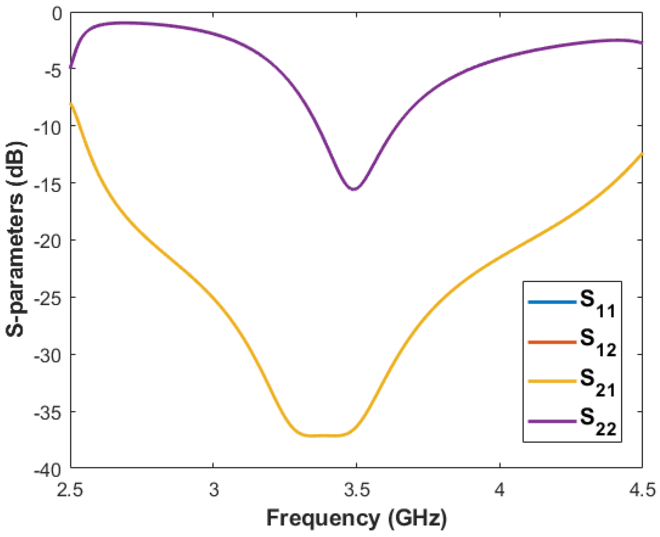
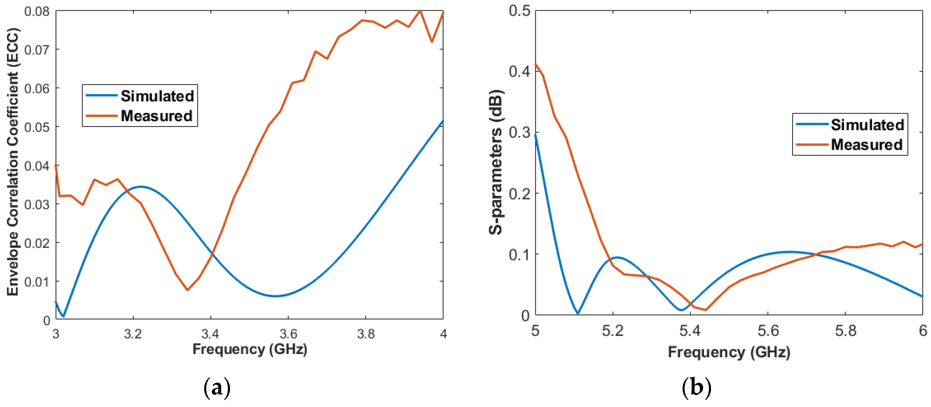
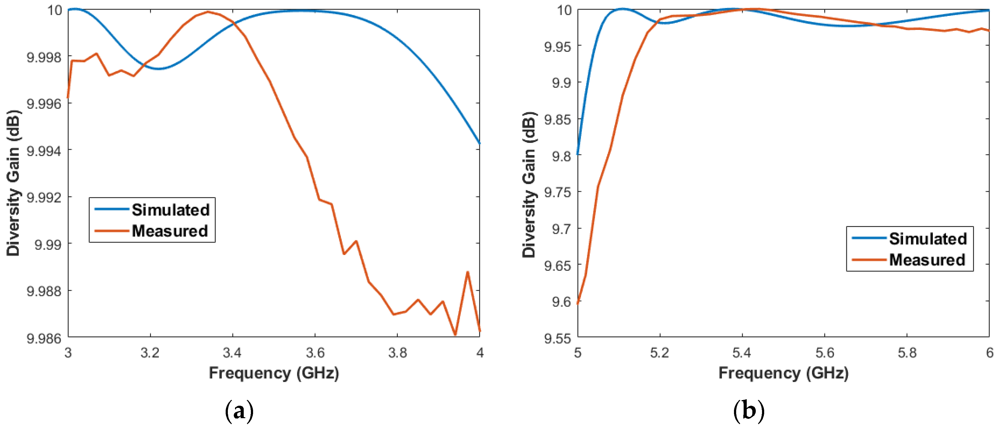
3.1. Antenna Performance

The simulated S-parameters of the proposed dual-band MIMO antenna after optimizations and application of decoupling techniques to improve the isolation between the ports are presented in Figure 11. As shown, the antenna operates in the 5G and WLAN bands, i.e., it exhibits impedance matching of less of than −6 dB over the bands ranging from 3.4 to 3.6 GHz and 5.15 to 5.85 GHz, respectively. High isolation is achieved over the operating bands, with less than −27 dB mutual coupling for the first band and less than −14 dB mutual coupling for the second band.
Thus, the MIMO antenna prototype is fabricated and measured for experimental characterization. A photograph of the device is shown in Figure 12.
The MIMO antenna measurement setup is the same as shown in Section 2.4. The measured S-parameters and the 2-D radiation patterns at 3.5 and 5.45 GHz are presented in Figure 13, which are compared to the simulated results, showing a good agreement between them. As can be observed, the antenna exhibits a good impedance matching and isolations with more than 19.8 dB and 16.75 dB over the two operating bands, respectively.
The radiation efficiency of the proposed antenna was also investigated, and the results are shown in Figure 14 for the first and second operating bands. As can be observed, the antenna presents an efficiency above 86% over the entire 5G band and an efficiency below 7.5 % over the entire WLAN band, except at 5.5 GHz, because the efficiency achieves a peak at 80%.
In addition, key performance parameters in MIMO antennas, such as the envelope correlation coefficient (ECC) and the diversity gain (DG), are investigated. The ECC is a factor that represents the correlation between two ports in a MIMO antenna—the lower the ECC values, the higher the diversity gain. To meet a good diversity performance, the ECC value must be lower than 0.5 [13]. For a two-port network, this parameter can be calculated by [14]:
ECC = | S * 11 S 12 + S * 21 S 22 | 2 ( 1 | S 11 | 2 | S 21 | 2 ) ( 1 | S 22 | 2 | S 12 | 2 )
Thus, the ECC values are calculated using (3). The simulated and measured results are presented in Figure 15 for the first and second operating bands.
As can be observed, the proposed MIMO antenna presents an ECC below 0.06 over the entire first operating band and below 0.11 over the entire second operating band, guaranteeing a good diversity capability of the device.
The DG parameter refers to the antenna capability to transmit the same information for two elements in a different way, guaranteeing even more diversity of the element [13]. This parameter can be calculated by:
DG = 10 1 ECC 2
Thus, the DG values are calculated using (4). The simulated and measured results are presented in Figure 16 for the first and second operating bands.
As can be observed, the proposed MIMO antenna presents an DG above 9.994 over the entire first operating band and above 9.971 over the entire second operating band, guaranteeing, once again, a good diversity capability of the device.

3.2. Comparison

Table 1 compares the performances of the proposed dual-band MIMO antenna with other two-element antennas recently reported in the literature. As can be observed, this work and reference [22] present the highest isolations among all works shown. In addition, the proposed antenna has the advantages of dual-polarization, the highest DG values, one of the lowest ECC values and the smallest size among all works analyzed.

4. Conclusions

In this paper, a compact two-element dual-polarized MIMO antenna for 5G applications and a compact two-element dual-polarized MIMO for 5G/WLAN applications are proposed. The design of both MIMO antennas consists of a pair of microstrip lines with step and a parasitic element placed between the pair of microstrip lines with step and slots etched in the ground plane. In the first MIMO antenna configuration, isolation better than 18 dB is achieved by the antenna. In the second MIMO antenna configuration, isolations better than 19.8 dB and 16.75 are achieved by the antenna for the first and second operating bands, respectively. Furthermore, for the second MIMO antenna configuration, key parameters of MIMO antennas such as ECC and DG are investigated, and appropriate values for ECC of lower than 0.06 and 0.11 are achieved by the first and second operating band, respectively; besides, appropriate values for DG of higher than 9.994 and 9.971 are achieved by the first and second operating band, respectively. In addition, the ECC and DG results are compared with other works recently reported in the literature and the radiation efficiency is investigated and analyzed. Therefore, the MIMO antenna proposed in this work is suitable and a good candidate for use in 5G/WLAN applications.

Author Contributions

S.B.P. contributed the idea, simulation, analysis, measurements, and paper writing, A.G.D.J. contributed to the analysis and measurements, V.P.S.N. contributed to the analysis, A.G.D. contributed the idea, analysis, and assisted in the work development and paper writing. All authors have read and agreed to the published version of the manuscript.

Funding

This research received no external funding.

Acknowledgments

This work was supported by CNPq under covenant 573939/2008-0 (INCT-CSF), CAPES, Federal University of Rio Grande do Norte (UFRN) and Federal Institute of Paraíba (IFPB).

Conflicts of Interest

The authors declare no conflict of interest.

References

  1. Ren, A.; Liu, Y.; Yu, H.W.; Jia, Y.; Sim, C.Y.D.; Xu, Y. A High-Isolation Building Block Using Stable Current Nulls for 5G Smartphone Applications. IEEE Access 2019, 60, 170419–170429. [Google Scholar] [CrossRef]
  2. Hu, W.; Qian, L.; Gao, S.; Wen, L.H.; Luo, Q.; Xu, H.; Liu, X.; Liu, Y.; Wang, W. Dual-Band Eight-Element MIMO Array Using Multi-Slot Decoupling Technique for 5G Terminals. IEEE Access 2019, 60, 153910–153920. [Google Scholar] [CrossRef]
  3. Mak, K.M.; Lai, H.W.; Luk, K.M.; Chan, C.H. Circularly Polarized Patch Antenna for Future 5G Mobile Phones. IEEE Access 2014, 2, 1521–1529. [Google Scholar]
  4. Ren, A.; Liu, Y.; Sim, C.Y.D. A Compact Building Block with Two Shared-Aperture Antennas for Eight-Antenna MIMO Array in Metal-Rimmed Smartphone. IEEE Trans. Antennas Propag. 2019, 60, 6430–6438. [Google Scholar] [CrossRef]
  5. WRC-15 Press Release—World Radiocommunication Conference Allocates Spectrum for Future Innovation. Available online: http://www.itu.int/net/pressoffice/press_releases/2015/56.aspx#.XrAwCKhKjIU (accessed on 11 April 2021).
  6. Zou, H.; Li, Y.; Xu, B.; Chen, Y.; Jin, H.; Yang, G.; Luo, Y. Dual-Functional MIMO Antenna Array with High Isolation for 5G/WLAN Applications in Smartphones. IEEE Access 2019, 7, 167470–167480. [Google Scholar] [CrossRef]
  7. Hong, W. Solving the 5G Mobile Antenna Puzzle: Assessing Future Directions for the 5G Mobile Antenna Paradigm Shift. IEEE Microw. Mag. 2017, 18, 86–102. [Google Scholar] [CrossRef]
  8. Parchin, N.O.; Al-Yasir, Y.I.A.; Ali, A.H.; Elfergani, I.; Noras, J.M.; Rodriguez, J.; Abd-Alhameed, R.A. Eight-Element Dual-Polarized MIMO Slot Antenna System for 5G Smartphone Applications. IEEE Access 2019, 7, 15612–15622. [Google Scholar] [CrossRef]
  9. Cui, L.; Guo, J.; Liu, Y.; Sim, C.Y.D. An 8-Element Dual-Band MIMO Antenna with Decoupling Stub for 5G Smartphone Applications. IEEE Antennas Wirel. Propag. Lett. 2019, 18, 2095–2099. [Google Scholar] [CrossRef]
  10. Li, Y.; Sim, C.Y.D.; Luo, Y.; Yang, G. High-Isolation 3.5 GHz Eight-Antenna MIMO Array Using Balanced Open-Slot Antenna Element for 5G Smartphones. IEEE Trans. Antennas Propag. 2019, 60, 3820–3830. [Google Scholar] [CrossRef]
  11. Xu, S.; Li, Y.; Gao, Y.; Gacanin, H. Opportunistic Coexistence of LTE and WiFi for Future 5G System: Experimental Performance Evaluation and Analysis. IEEE Access 2018, 6, 8725–8741. [Google Scholar] [CrossRef]
  12. Zhang, R.; Wang, M.; Cai, L.X.; Zheng, Z.; Shen, X.; Xie, L. LTE-Unlicensed: The Future of Spectrum Aggregation for Cellular Networks. IEEE Wirel. Commun. 2015, 22, 151–159. [Google Scholar] [CrossRef]
  13. Oliveira, J.G.D.; D’Assunção Junior, A.G.; Silva Neto, V.P.; D’Assunção, A.G. New compact MIMO antenna for 5G, WiMAX and WLAN technologies with dual polarisation and element diversity. IET Microw. Antennas Propag. 2021, 15, 415–426. [Google Scholar] [CrossRef]
  14. Khan, A.A.; Jamaluddin, M.H.; Aqeel, S.; Nasir, J.; Kazim, J.u.R.; Owais, O. Dual-band MIMO dielectric resonator antenna for WiMAX/WLAN applications. IET Microw. Antennas Propag. 2017, 11, 113–120. [Google Scholar] [CrossRef]
  15. Jehangir, S.S.; Mohammad, S.S.; Shamim, A. Highly miniaturised semi-loop meandered dual-band MIMO antenna system. IET Microw. Antennas Propag. 2018, 12, 864–871. [Google Scholar] [CrossRef]
  16. Kwon, D.; Khang, S.T.; Yeo, T.D.; Hwang, I.J.; Lee, D.J.; Yu, J.W.; Lee, W.S. Dual-Band Half-Elliptic Hoof Antenna With Mathieu Function for a Femto-Cell Network. IEEE Trans. Antennas Propag. 2017, 65, 1047–1054. [Google Scholar] [CrossRef]
  17. Li, Z.; Yin, C.; Zhu, X. Compact UWB MIMO Vivaldi Antenna with Dual Band-Notched Characteristics. IEEE Access 2019, 7, 38696–38701. [Google Scholar] [CrossRef]
  18. Zhao, X.; Riaz, S.; Geng, S. A Reconfigurable MIMO/UWB MIMO Antenna for Cognitive Radio Applications. IEEE Access 2019, 7, 46739–46747. [Google Scholar] [CrossRef]
  19. Ameen, M.; Ahmad, O.; Chaudhary, R.K. Single split-ring resonator loaded self-decoupled dual-polarized MIMO antenna for mid-band 5G and C-band applications. AEU Int. J. Electron. Commun. 2020, 124, 153336. [Google Scholar] [CrossRef]
  20. Sohi, A.K.; Kaur, A. Sextuple band rejection functionality from a compact Koch anti-snowflake fractal UWB-MIMO antenna integrated with split-ring resonators and slots. AEU Int. J. Electron. Commun. 2021, 138, 153898. [Google Scholar] [CrossRef]
  21. Soltani, S.; Lotfi, P.; Murch, R.D. A Dual-Band Multiport MIMO Slot Antenna for WLAN Applications. IEEE Antennas Wirel. Propag. Lett. 2017, 16, 529–532. [Google Scholar] [CrossRef]
  22. Peng, H.; Zhi, R.; Yang, Q.; Cai, J.; Wan, Y.; Liu, G. Design of a MIMO Antenna with High Gain and Enhanced Isolation for WLAN Applications. Electronics 2021, 10, 1659. [Google Scholar] [CrossRef]
  23. Desai, A.; Palandoken, M.; Elfergani, I.; Akdag, I.; Zebiri, C.; Bastos, J.; Rodriguez, J.; Abd-Alhameed, R.A. Transparent 2-Element 5G MIMO Antenna for Sub-6 GHz Applications. Electronics 2022, 11, 251. [Google Scholar] [CrossRef]
  24. Yang, R.; Xi, S.; Cai, Q.; Chen, Z.; Wang, X.; Liu, G. A Compact Planar Dual-Band Multiple-Input and Multiple-Output Antenna with High Isolation for 5G and 4G Applications. Micromachines 2021, 12, 544. [Google Scholar] [CrossRef] [PubMed]
  25. Wu, S.; Chi, L.; Li, F.; Paulis, F.; Qi, Y. A Compact High-Isolation Wideband Three-Sector Linear Array. IEEE Trans. Antennas Propag. 2022, 70, 3094–3099. [Google Scholar] [CrossRef]
  26. Gao, D.; Cao, Z.X.; Fu, S.D.; Quan, X.; Chen, P. A Novel Slot-Array Defected Ground Structure for Decoupling Microstrip Antenna Array. IEEE Trans. Antennas Propag. 2020, 68, 7027–7038. [Google Scholar] [CrossRef]
  27. Huang, J.; Dong, G.; Cai, Q.; Chen, Z.; Li, L.; Liu, G. Dual-Band MIMO Antenna for 5G/WLAN Mobile Terminals. Micromachines 2021, 12, 489. [Google Scholar] [CrossRef]
  28. Al-Gburi, A.J.A.; Ibrahim, I.M.; Zakaria, Z.; Abdulhameed, M.K.; Saeidi, T. Enhancing Gain for UWB Antennas Using FSS: A Systematic Review. Mathematics 2021, 9, 3301. [Google Scholar] [CrossRef]
  29. Souza, E.A.M.; Oliveira, P.S.; D’Assunção, A.G.; Mendonça, L.M.; Peixeiro, C. Miniaturization of a Microstrip Patch Antenna with a Koch Fractal Countour Using a Social Spider Algorithm to Optimize Shorting Post Position and Inset Feeding. Int. J. Antennas Propag. 2019, 2019, 6284830. [Google Scholar] [CrossRef]
  30. Rahman, M.; Park, J.-D. The Smallest Form Factor UWB Antenna with Quintuple Rejection Bands for IoT Applications Utilizing RSRR and RCSRR. Sensors 2018, 18, 911. [Google Scholar] [CrossRef] [Green Version]
Figure 1. The proposed MIMO antenna configuration: (a) side view, (b) top view, and (c) bottom view.
Electronics 11 01943 g001aElectronics 11 01943 g001b
Figure 2. First step in antenna design: (a) top view, (b) bottom view, and (c) corresponding S-parameters results.
Electronics 11 01943 g002
Figure 3. Simulated surface current densities at 3.5 GHz for (a) port 1 and (b) port 2 excitations.
Electronics 11 01943 g003
Figure 4. Antenna design after the slots is etched in the ground plane: (a) top view, (b) bottom view, (c) S11/S22, and (d) S12/S21 results for different values of Ls.
Electronics 11 01943 g004
Figure 5. Decoupling element design to improve isolation: (a) L-shaped stubs are placed between the radiating elements and (b) the S-parameters curved are presented; (c) the L-shaped stubs are connected by a microstrip line and (d) the S-parameters curves are presented.
Electronics 11 01943 g005
Figure 6. Diagonal slot design of the ground plane to improve isolation: surface current densities for (a) port 1 and (b) port 2; (c) representation of the ground plane after insertion of the slot, (d) S12/S21 and (e) S11/S22 results for different values of the slot length.
Electronics 11 01943 g006aElectronics 11 01943 g006b
Figure 7. Simulated S-parameters results of the proposed MIMO antenna.
Electronics 11 01943 g007
Figure 8. Proposed MIMO antenna prototype: (a) top view and (b) bottom view.
Electronics 11 01943 g008
Figure 9. Proposed MIMO antenna simulated and measured parameters. (a) Measurement setup. (b) Measured S-parameters. Port 1 results: (c) Simulated and (d) measured 2-D radiation patterns at 3.5 GHz and ϕ = 0° (x-z plane) in red color, and ϕ = 90° (y-z plane) in black color. Port 2 results: (e) Simulated and (f) measured 2-D radiation patterns at 3.5 GHz and ϕ = 0° (x-z plane) in red color, and ϕ = 90° (y-z plane) in black color. Simulated 3-D radiation patterns results at 3.5 GHz: (g) Port 1 and (h) port 2.
Electronics 11 01943 g009aElectronics 11 01943 g009b
Figure 10. The proposed dual-band MIMO antenna configuration: (a) side view, (b) top view, and (c) bottom view.
Electronics 11 01943 g010aElectronics 11 01943 g010b
Figure 11. Simulated S-parameters results of the proposed dual-band MIMO antenna.
Electronics 11 01943 g011
Figure 12. Dual-band MIMO antenna prototype: (a) top view and (b) bottom view.
Electronics 11 01943 g012
Figure 13. Proposed dual-band MIMO antenna simulated and measured parameters. (a) Measured S-parameters. Port 1 results: (b) Simulated and (c) measured 2-D radiation patterns at 3.5 GHz and ϕ = 0° (x-z plane) in red color, and ϕ = 90° (y-z plane) in black color. Port 2 results: (d) Simulated and (e) measured 2-D radiation patterns at 3.5 GHz and ϕ = 0° (x-z plane) in red color, and ϕ = 90° (y-z plane) in black color. Port 1 results: (f) Simulated and (g) measured 2-D radiation patterns at 5.45 GHz and ϕ = 0° (x-z plane) in red color, and ϕ = 90° (y-z plane) in black color. Port 2 results: (h) Simulated and (i) measured 2-D radiation patterns at 5.45 GHz and ϕ = 0° (x-z plane) in red color, and ϕ = 90° (y-z plane) in black color. Simulated 3-D radiation patterns results at 3.5 GHz: (j) Port 1 and (k) port 2. Simulated 3-D radiation patterns results at 5.45 GHz: (l) Port 1 and (m) port 2.
Electronics 11 01943 g013aElectronics 11 01943 g013bElectronics 11 01943 g013c
Figure 14. Radiation efficiency results for the (a) first and (b) second operating bands.
Electronics 11 01943 g014
Figure 15. Measured ECC results for the (a) first and (b) second operating bands.
Electronics 11 01943 g015
Figure 16. Measured DG results for the (a) first and (b) second operating bands.
Electronics 11 01943 g016
Table 1. Comparison between the proposed work and the referenced two-element MIMO antennas.
ReferenceBand (GHz)Size (mm2)Isolation (dB)PolarizationDG (dB)ECC
[13]3.1–5.235 × 35>10Dual>9.9<0.1
[14]3.4–3.7
5.15–5.35
50 × 50>13
>16
NA>9.956
>9.963
<0.131
<0.002
[15]1.27–1.43
1.8–2.133
50 × 120>15NA>9.6<0.0785
[16]0.88–0.96
1.71–2.17
219.9 × NA>10
>NA
NANANA
[17]2.9–11.626 × 26>16NANA0.02
[18]1–4.5120 × 60>12.5NANA<0.19
[19]3.4–3.6
4–8
46 × 21>12
>15
Linear (first band)
Circular (second band)
10<0.003
[20]2.48–15.4229.5 × 43.5>17NA>9.773<0.019
[21] 12.4–2.5
4.9–5.8
46 × 20>14
>12
NANA<0.001
<0.27
[22]2.12–2.8
4.95–6.65
50 × 40>14
>21
LinearNA<0.01
<0.024
[23]4.65–4.97 (case 1)
4.67–4.94 (case 2)
50 × 35>15NA>9.96
>9.94
<0.02
[24]2.5–2.57
3.17–3.77
32 × 32>15NANA<0.02
This work3.4–3.6
5.15–5.85
25 × 25>19.8
>16.75
Dual>9.994
>9.971
<0.06
<0.11
1 In this referenced work, the antenna can operate with two or four ports (for the second operating band). Thus, in our analysis, we considered the operation with only two ports.
Publisher’s Note: MDPI stays neutral with regard to jurisdictional claims in published maps and institutional affiliations.

