Article

Feasible and Optimal Design of an Airborne High-Temperature Superconducting Generator Using Taguchi Method

1
Quanzhou Institute of Equipment Manufacturing, Haixi Institutes, Chinese Academy of Sciences, Quanzhou 362200, China
2
University of Chinese Academy of Sciences, Beijing 100049, China
3
The School of Automation, Northwestern Polytechnical University, Xi’an 710072, China
4
Autospark Technology Co., Ltd., Shenzhen 518103, China
5
AVIC Shaanxi Aero Electric Co., Ltd., Xi’an 710065, China
*
Author to whom correspondence should be addressed.
Electronics 2022, 11(12), 1901; https://doi.org/10.3390/electronics11121901
Submission received: 19 May 2022 / Revised: 6 June 2022 / Accepted: 10 June 2022 / Published: 17 June 2022
(This article belongs to the Section Semiconductor Devices)

Abstract

:
Aircraft electrification has become a tendency with demands for low carbon emissions and high electrical load capacity nowadays. Aircraft are especially strict with onboard weight; as a result, high-temperature superconducting (HTS) electrical machines are drawing attention for airborne applications due to their potential for a significant increase in power density. In this study, a feasible scheme of a hybrid-HTS airborne synchronous generator was proposed to fulfill the requirements of a small aircraft (with fewer than eight seats and a maximum range of about 1000 km). The full design from top to bottom is described. The output characteristics and metallic and superconducting AC losses were calculated based on the finite element method. The power grade of 1 MW was obtained, with a power density of 9.27 kW/kg and an efficiency of 98.73%. Furthermore, the performance of the machine was optimized using the Taguchi method. The preliminary design demonstrated the possibility and benefits of hybrid-HTS machines for airborne applications.

1. Introduction

The aviation industry has seen a rise in demand for new power-supply systems with a high power grade and high power density in recent years as the enhanced-electrification of aircrafts has progressed [1,2,3,4]. Conventional materials and systems architectures are approaching their performance limits and cannot meet the dual requirements for the weight reduction and power increase of the future generation of aircraft. An HTS generator with an accompanying aviation power system is one of the most promising options [5,6,7,8,9].
Superconducting electric machines of various power grades and application areas have been studied. Frederick Berg et al. investigated the use of superconducting technology in distributed propulsion aircrafts, proposing performance requirements for superconducting electric machines and giving the reference relation between the power and weight of the cooling system and the total power and weight of the power generation system [10,11]. Mykhaylo Filipenko et al. designed a 10 MW superconducting generator for direct coupling to an airborne gas turbine, concluding that a dry weight below 500 kg, i.e., a power density beyond 20 kW/kg, is achievable [
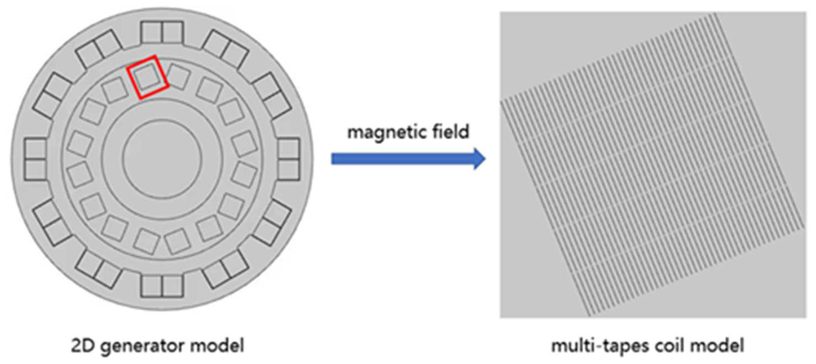
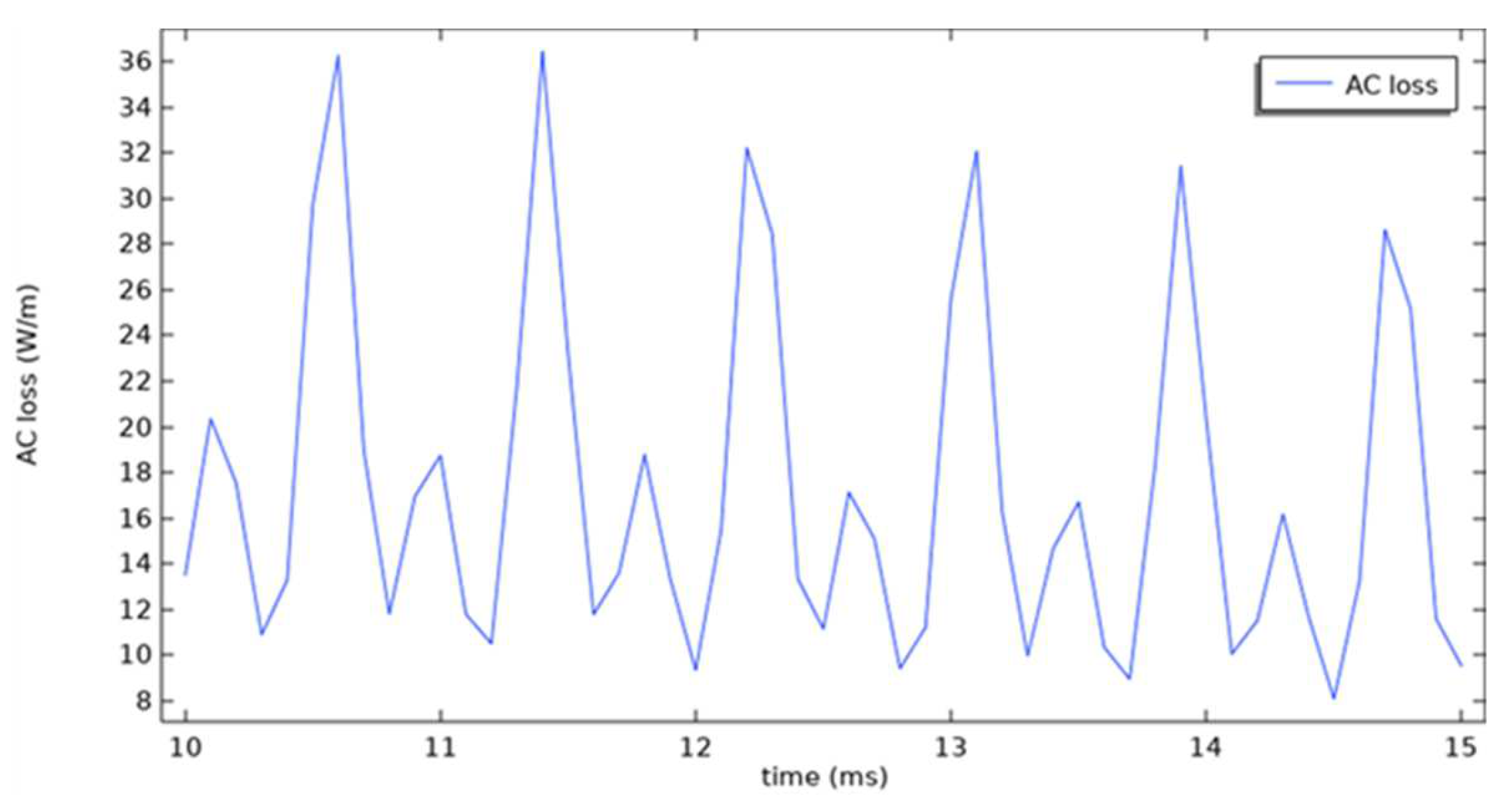
12]. Tara Benkel et al. applied the T–A formulation to HTS-coated conductors in a rotating machine and measured AC loss, proving the possibility of the thin-strip approximation in T–A formulation [13]. Despite all of these studies, the question of how to design an HTS aircraft electric machine from scratch to fulfill specific criteria, as well as the process of performance optimization, remains unanswered. We hoped to sort out the process for designing an HTS aircraft generator based on the application field and performance requirements, which would be valuable for engineering. The process is shown in Figure 1.
We believed that superconducting generator design and optimization can benefit greatly from the design steps and optimization methodologies used in conventional generators. In this study, a superconducting aircraft generator was designed mainly based on the design procedure of a traditional non-superconducting generator. It was expected to have a 1 MW output, a power density of over 8 kW/kg, and a 98% efficiency. These performance target parameters were chosen in order to balance research value with future practical feasibility. The generator was expected to be employed in general turbo-electric aircraft with HVDC (high-voltage direct-current) architecture. The turbine engine powers the generator, which then sends electricity to the HVDC power system, turning the tail motors and powering other electrical loads. In addition to this system, the aircraft was equipped with hydrogen fuel cells as a backup power-generation system. We developed 2D hybrid-HTS generator models using COMSOL Multiphysics (Version 5.6, Comsol Inc., Burlington, MA, USA), and T–A formulation was used to calculate the AC loss. The design progress of the HTS generator is explained, and simulation results show that the model met the expected performance targets. The cooling of the superconducting generator was linked to the hydrogen storage of the multi-electric aircraft via a modular pipe cooling system that used liquid hydrogen as a coolant. The generator’s rotor AC loss and other non-superconducting losses are discussed in detail. The generator’s performance was improved by applying the Taguchi method, which also verified the feasibility of the Taguchi method when applied to the HTS generator.
The remainder of this paper is organized as follows. Section 2 introduces the detailed design process of the generator. In Section 3, 2D finite-element HTS models are established, the electromagnetic and thermal properties are analyzed, and the AC loss is calculated using the T–A formulation. The Taguchi method is used to optimize the basic performances of the generator in Section 4. Finally, Section 5 provides some concluding remarks on the paper.

2. Generator Design

Despite multiple research and demonstration projects, there are currently no standardized design procedures for HTS electric machines. Design specifics for the HTS generator must be dependent on the aircraft’s specific requirements. We must first define the type of generator before designing detailed geometric characteristics. The requirements of both aviation power systems and the superconducting material must be taken into account.
We began by considering the architectures of aviation power systems before formally discussing the selection of the generator. Since the most important direction for aircraft performance optimization is weight reduction, low-voltage architectures are ruled out. The pure HVDC architecture is better at saving the weight of the wiring system [14]. However, the hybrid HVAC (high-voltage alternating-current)/HVDC architecture is better for reducing the number of power conversion units, considering some loads are frequency wild-compatible [14], which is good for saving the weight of heat sinks. Since the development of power electronic devices’ DC architecture will become more promising, we chose DC architecture. The advantages of an HVDC system include isolating system faults, low loss, and low electromagnetic interference. The generator used in HVDC systems is preferred as superconductors have nearly no loss in DC transmission and the critical current is affected by magnetic fields.
The generators commonly used in aviation HVDC power systems include permanent magnet synchronous machines (PMSM), three-stage brushless synchronous machines, switched reluctance machines (SRM), electrically excited doubly salient pole machines, and asynchronous machines. Due to the limited mechanical strength of HTS materials, the generator’s speed should not be too high. Given the cooling system required by superconductors, the generator’s structure should not be complicated. A synchronous generator appeared to be an option worth considering. Early HTS electric machine research focused mostly on wind power generation and ship propulsion, and the studies on aircraft generators/motors have increased in recent years [15,16,17,18,19,20]. Although some novel electric machine structures have been proposed, synchronous machines are still the first choice for most superconducting electric machine research. Considering the existing MW-level superconducting electric machine projects and the safety and reliability requirements of the aircraft generator, we finally chose the classic synchronous machine.
The hybrid-superconducting construction was chosen based on the practicality of future production and experimentation, with rotor-excitation windings made of YBCO tapes and stator-armature windings made of copper wires. The rotor HTS coils worked at 20 K and were cooled by liquid hydrogen, while the generator housing was air-cooled like a conventional generator. More details of the cooling system are shown in Section 3.
The rotor had an air-core structure to reduce weight and increase excitation, which was helpful for improving power density. An aluminum metal barrel surrounded the HTS coils, acting as a vacuum chamber and electromagnetic shielding.
When the air-gap width, armature diameter, and rated stator current are constant, the electromagnetic torque can be enhanced by increasing the number of poles, hence improving the power density [21]. As the number of pole pairs increases, the overall loss increases, and the weight decreases when the generator’s size remains constant [21]. The number of pole pairs of the generator should meet the dual requirements of power grade and efficiency. The relationship between the number of poles and slots is shown as:
q = Z 2 p m
where q is the number of slots per pole per phase, Z is the number of stator slots, p is the number of pole pairs, and m is the number of winding phases. The stator fractional-slot winding (when q is a fraction) reduces the machine’s torque fluctuation and optimizes the induced voltage waveform [22]. The generator was set at 8 poles and 12 slots, based on the number of poles and slots in previous HTS generator examples [23,24,25,26,27].
The common rotor structures of synchronous machines include surface mount and built-in types. The coil of the built-in rotor is placed in the rotor’s inner slot, which eliminates the risk of the coil being flung out as the rotor rotates at high speeds. Simultaneously, it can achieve a higher electromagnetic torque, which aids in the development of power density and overload capacity. A built-in rotor structure was chosen to ensure the superconducting generator’s safety, reliability, and high power density in an aircraft power system.
The air gap in most synchronous machines is less than 3 mm, while the air gap in certain wind turbines is more than 50 mm [28,29]. A hybrid-HTS machine tends to have a wider air gap than a full HTS machine. In this study, the air gap width was set at 15 mm, taking into account the space required for electromagnetic shielding and future fabrication.
When the bus voltage level of a multi-electric aircraft power system increases, the total weight and total loss increase [
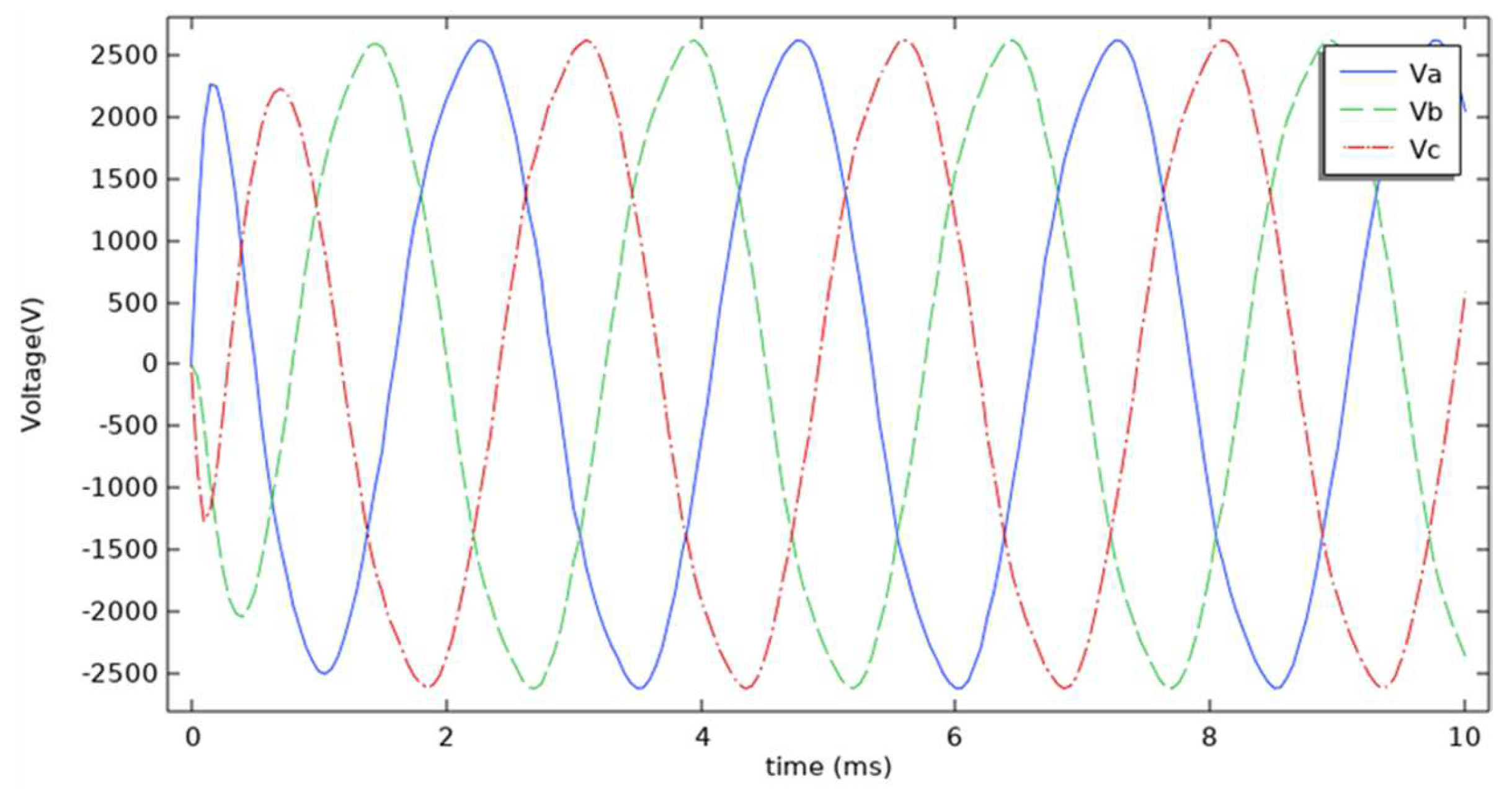
30]. Although the weight and loss of an HTS generator are not sensitive to the voltage level, the influence of the voltage level must be considered as the generator is designed as the core of the power system. Considering the limitation of the current-carrying capacity of the stator winding copper coils, the on-load peak voltage of the HTS generator was set at 2.5 kV.
The speed was chosen at 6000 rpm as a compromise between the high speed of an aircraft turbine engine and the low speed of the HTS prototype in previous research [31]. Following the determination of the number of pole pairs and rotating speed, the frequency was determined to be 400 Hz, which is also the common frequency in current aircraft power systems.
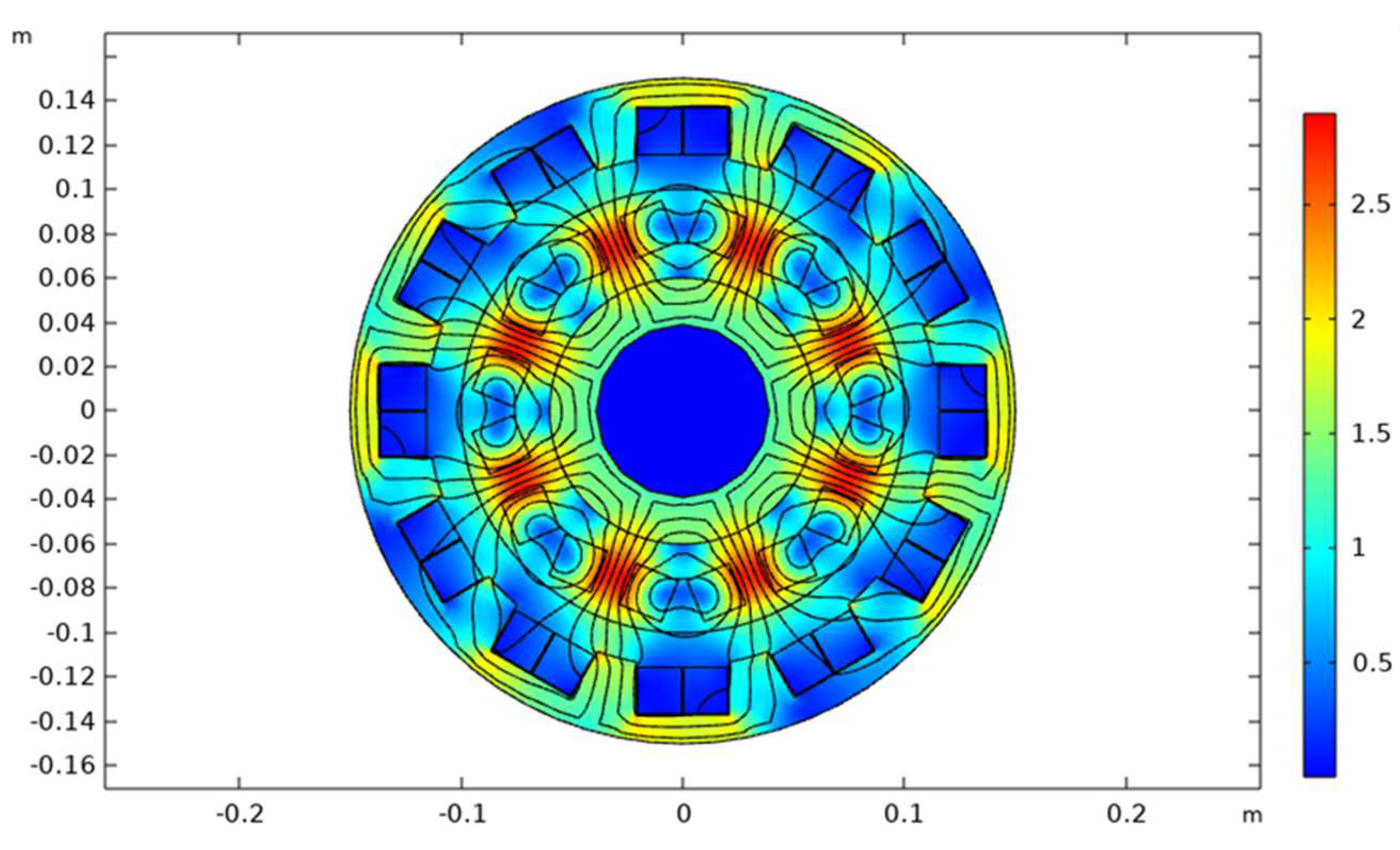
In our design, since the peak density of air-gap flux density was expected to be about 1 T, the peak density of the rotor flux density needed to reach 2 T considering the attenuation of magnetic field transmission caused by a wide air gap [32]. According to the desired flux density, the geometric size of a generator can be reversely designed. The corresponding formulas of rotor flux density and gap flux density are shown as follows [33,34]:
B r = μ 0 A 2 ( r 0 r f o ) p + 1 [ 1 + η λ s ( r f o r s i ) 2 p ]
B g a p = μ 0 A 2 ( r 0 r f o ) p + 1 [ 1 + η λ s ( r a i r s i ) 2 p ]
where μ0 is the vacuum permeability, A is the current layer density, r0 is the average radius of the excitation winding, rfo is the outer radius of the excitation winding, p is the number of pole pairs, rsi is the inner radius of the stator core, and rai is the inner radius of the stator-armature winding. The coefficient ηλs is set at 1.
Armature line load As can be calculated by:
A s = 2 m N I s π D s
where m is the number of phases, N is the number of turns in series per phase of the armature, Is is the stator current, and Ds is the diameter of stator-armature winding.
The output power P of a synchronous generator can be calculated by [35]:
P = π 2 2 N 0 60 k W B g a p A s D s 2 L
where N0 is the generator speed, kW is the winding factor, and L is the effective shaft length of the machine.
The phase-induced electromotive force of the generator can be calculated by [35]:
E p = 1 2 2 π N 0 60 r a B g a p L n 0 q p
where ra is the radius of stator-armature winding, n0 is the number of conductors in each slot, and q is the number of stator slots in each phase at each pole.
YBCO tapes were used to manufacture racetrack coils. The rotor-excitation windings consisted of 8 five-pancake coils; each single-pancake coil had 45 turns. Such a structure was designed to generate a large-enough rotating magnetic field with a wide air gap. The parameters of the tape are shown in Table 1.
The structure of the generator is illustrated in Figure 2 (excluding the cooling system), and the initial design parameters are shown in Table 2.

3. Finite Element Models and Results

3.1. Electrical and Magnetic Characteristics of the Generator

COMSOL Multiphysics was used to create a 2D finite-element model of a hybrid-HTS generator. Compared with a 3D model, the 2D model simulation can save a lot of time on the premise of ensuring the accuracy of AC-loss calculation.
The magnetic flux cloud map is shown in Figure 3. The flux density (absolute value) of the rotor and air gap are shown in Figure 4, with peak values of 2.65 T and 1.28 T, respectively. Figure 5 shows the flux density (absolute value) sampled from four corners of a stator coil, demonstrating that the magnetic field at different sampling points was very different. The three-phase stator voltage with load is shown in Figure 6. The peak voltage reached 2620 V, and the harmonic distortion rate of the voltage waveform was less than 5%.

3.2. Cooling System Design and AC Loss

The AC loss of stator HTS coils is a focus of research in full-HTS machines, while the AC loss of rotor coils is always ignored. We aimed to get an exact value through simulation since we were not satisfied with knowing that the rotor AC loss was an existing small loss.
The magnetic field (including amplitude and direction) of the rotor coil was sampled in our 2D HTS generator model. A multi-tape model with a total number of turns of 225 was established to simulate the straight part of a rotor coil. The magnetic field sampled was added to the multi-tape model, as shown in Figure 7. The racetrack coil was the type of HTS coil employed in this model, and only the coil’s straight parts were taken into account, while the curved parts were omitted. This is because the AC loss occurs primarily in straight parts. The AC loss of rotor HTS windings was calculated by the T–A formulation [36,37,38,39]. Compared with other methods like the H formulation, the T–A formulation is excellent at calculating the AC loss of HTS tape with a high width-to-thickness ratio quickly. The HTS tapes are actually through DC, and the loss is primarily caused by the harmonic magnetic field generated by the stator slot structure. The term “AC loss” is a habitual name.
The non-linear resistivity of superconductor is reflected by EJ power law:
E = E 0 ( J J C ( B ) ) n
where E0 is the critical electric field, which is generally 10−4 V/m, and Jc(B) is the critical current density dependent on the magnetic field.
The relationship between critical current density and flux density and temperature is shown as:
J C ( B , T ) = J c 0 I ( T ) ( 1 + k ( T ) 2 B p a r 2 + B p e r 2 B c ( T ) ) b ( T )
where Jc0 is the critical current density under the self-field, Jc(B, T) is the critical current density varying with magnetic field and temperature, Bpar is the flux density component parallel to the tape surface, Bper is the perpendicular component, and I, b, k, and Bc are the parameters varying with temperature.
The current density vector potential T is defined in the superconducting domain to solve the current density J distribution of the HTS-coated conductor:
J = × T
In the 2D model, the boundary condition of the T formulation is shown as:
I t a p e = 0 l J z d l = 0 l T x d x = T 1 T 2 = T 1
where T1 is the vector potential of current density along the width side of the tape, and T2 is the vector potential of current density on the other side (set to 0).
The magnetic vector potential A is used in the non-superconducting domain, and the A formulation is shown as:
1 μ × ( × A ) + σ A t = 0
where μ is the permeability, σ is the conductivity, and the boundary condition of the magnetic vector potential is set as A = 0.
Referring to the cooling systems in previous studies, we designed a modular pipe cooling system as shown in Figure 8 [40,41]. In the cooling system, each HTS coil was contained in a modular pipe separately and cooled by liquid hydrogen. Pumps linked all pipelines to the liquid hydrogen tank and circulated the liquid hydrogen. Gaseous hydrogen produced by heat absorption in the cooling system can be used in aircraft hydrogen fuel cells. Compared with cooling the whole rotor in a Dewar flask, we only cooled the HTS coils, thus reducing the load of the refrigerator. It is worth noting that this cooling method, while reducing load and improving efficiency, leads to complex installation processes and lower reliability. Further research will look into the issues of refrigeration load and system complexity.
The temperature distribution and normalized critical current density are shown in Figure 9 and Figure 10, and the AC loss is illustrated in Figure 11. The magnetic field was basically parallel to the surface of the HTS tapes, and the operating temperature was kept at about 20 K, which led to low rotor AC loss. The total AC loss of all the HTS coils was 77.6 W.

3.3. Results

Under the condition of 10 ohms of pure resistive load per phase, the generator’s single-phase peak voltage was 2620 V, and the total output power was 1.03 MW, which met the expected requirement.
The total weight of the superconducting generator is the sum of the weights of all components. When calculating the volume, we used numerical calculation as a supplement to the simulation to avoid the error caused by the lack of curved parts in the 2D model. Table 3 lists the materials and weights of each component, where the weight of the superconducting windings is estimated according to the density of Hastelloy. Based on the results of simulation and numerical calculation, the generator’s total weight was 111.10 kg, indicating that the design met the expected power density.
We examined the composition of the HTS generator’s loss in depth to see whether the expected efficiency was achieved. The HTS generator’s losses were largely composed of stator iron loss, stator copper loss, HTS rotor AC loss, and additional loss.
The iron loss Piron can be calculated by the Steinmetz equation [42]:
P i ˙ r o n = ( K h f B m a + K C f 2 B m 2 ) · V
where Kh is the hysteresis loss coefficient, f is the frequency, Bm is the maximum value of air-gap flux, a is the Steinmetz coefficient, Kc is the eddy current loss coefficient, and V is the volume of the stator core. For the iron core of DW360_50, when f is 400 Hz, Kh is 176.84, and Kc is 0.87 from the BP curve of the corresponding frequency. As the peak value of air gap magnetic density at the sampling point was 1.28 T, a was set as 2, and thus the iron loss value calculated was 1.772 kW.
The copper loss of the stator winding is calculated by:
P C u = I 2 R = I 2 N ρ C u L S
where I is the RMS stator current, R is the total resistance of the stator windings, N is the total number of copper wires, ρCu is the resistivity of the copper wire, L is the length of a whole coil (including the curved parts), and S is the cross-sectional area of a single wire. It is worth noting that in the hybrid-HTS generator, the temperature of the stator copper windings increases significantly, and the copper resistivity should be taken at the value of a stable operating temperature. In this design, the copper windings were finally heated up to about 506 K (233 °C), the corresponding copper resistivity was 0.02515 mm2/m, and the total copper loss was 8.124 kW.
Additional generator losses include mechanical and extra electrical losses. Mechanical losses are made up of ventilation and bearing friction losses, which account for 20% of total losses in most traditional generators and rise as speed increases. Bearing friction loss can be neglected in a machine with high speed and electromagnetic bearings since the shaft has no direct contact with the bearing and does not require lubrication. As the hybrid-HTS generator requires cooling and sealing, the ventilation loss is seen as 0.
Extra electrical losses include the loss caused by end-flux leakage in surrounding iron components, the loss caused by various harmonic fluxes, the iron loss caused by tooth harmonics and high order harmonics on the rotor surface, and so on. The electrical additional loss of a traditional machine is comparable to its iron loss and is estimated by proportion in design. In our design of the HTS generator, the additional electrical loss was set to account for 25% of the total loss, conservatively.
The loss components are listed in Table 4. It can be concluded that the total loss of the hybrid-HTS generator was 13.298 kW, and the efficiency was 98.725% (excluding the cooling system). The stator coils’ copper loss was the generator’s major loss, whereas the rotor superconducting coils’ AC loss was less than 1% of the total loss, showing the superconductor’s superiority in carrying huge DC.
According to the results of finite-element model simulation and numerical calculation, the hybrid-HTS generator designed according to the initial parameters reached the expected power value of 1 MW, the power density of 8 kW/kg, and efficiency of 98%. Detailed performances of the generator are listed in Table 5.

4. The Taguchi Method on Performance Optimization

Though the hybrid-HTS generator met the design indicators, there is a need for improvement in the generator’s performance, which must be accomplished through parameter optimization.
Dr. Taguchi from Japan created a local optimization method based on orthogonal trials and signal-to-noise ratio technology [43]. By creating an orthogonal table, the best combination of various design parameters in a multi-objective optimization design can be found with the fewest number of experiments [43]. The three primary steps of the Taguchi method are:
(1)
Determine the optimization parameters, their variation values, and the optimization objectives.
(2)
Create an orthogonal table, and build a simulation model for each element in the table.
(3)
Analyze the influence degree of each optimization parameter, find the ideal combination, and test it.
The Taguchi method is commonly used in the research and engineering of conventional generators but not in the design of HTS generators. Instead of going directly to more efficient but complex optimizations, we needed to first verify the feasibility of the Taguchi approach for HTS generator performance optimization and set the groundwork for a future particular optimization strategy. In this study, output power, power density, and efficiency were chosen as the optimization objectives. The number of turns of a stator coil (A), air gap width (B), core length (C), stator core thickness (D) are taken as optimization parameters, and three value levels are taken for each parameter. The corresponding configuration is shown in Table 6. A, B, C, and D represent the four optimization parameters.
Taguchi’s orthogonal table is expressed as Ln (Ak), where A represents the number of levels, k represents the number of optimization parameters, and n represents the number of experiments, n = A2. In this study, there were three level values and four optimization parameters, corresponding to nine optimization designs. Finite element simulation was carried out for each optimization scheme, and the output power, copper loss, and efficiency were calculated and recorded. The orthogonal table and optimization results are shown in Table 7.
According to the optimization results of the nine schemes, the average values of the generator’s output power, power density, and efficiency under different level values of parameters were calculated and are listed in Table 8, which reflects the importance of different parameters to three optimization objectives and the optimal level value of each parameter.
Based on the results shown in Table 8, the number of a stator coil was set as 23 (level 3), the air-gap width was set as 14.5 mm (level 1), the core length was set as 305 mm (level 3), and the stator core thickness was set as 35 mm (level 2) in the final design, corresponding to scheme 7 in Table 7. The output power and power density of the optimized scheme were higher than those of the original design, while the efficiency was slightly reduced. It is worth noting that different combinations of optimization parameters can be obtained when optimization objects have different priorities (for example, when efficiency is prioritized). The optimization results in this study prove the effectiveness of the optimization and preliminarily confirm the feasibility of the Taguchi method for HTS generator optimization.
It was discovered that the stator’s copper windings limited the hybrid-HTS generator’s performance in terms of heat, loss, space, and other factors, which was not fully reflected in the existing optimization scheme. More optimization objectives will be optimized simultaneously in the future, and optimization parameters will be chosen more reasonably.

5. Conclusions

In this study, an aircraft HTS generator was designed, a kind of modular pipe-cooling system was proposed and discussed, the finite element method was utilized for modeling and simulation, and the Taguchi method was employed to optimize the generator performance. The following conclusions are obtained through simulation results and analysis.
(1)
A 1 MW hybrid-HTS generator was designed with a power density of 9.27 kW/kg and an efficiency of 98.725% (excluding the cooling system). Its design procedure was similar to that of a normal generator, which researchers and engineers of superconducting machines can utilize as a reference.
(2)
The plan of modular pipe cooling was proposed and modeled, using liquid hydrogen as a coolant to achieve both superconductor cooling and aircraft weight reduction.
(3)
The principal loss in the hybrid-HTS generator was copper loss of stator windings (more than 60%), and the AC loss of rotor HTS windings accounted for the least (less than 1%). The copper windings of the stator were the main constraint of the performance of the hybrid-HTS generator.
(4)
The Taguchi method was preliminarily tested for its availability to optimize the performance of a hybrid-HTS generator, showing that this performance optimization method commonly used in conventional generators can be applied to HTS aircraft generators.

Author Contributions

Conceptualization, S.S.; methodology, W.C.; formal analysis, J.X.; investigation, M.Y.; supervision, Z.C.; writing—original draft preparation, X.Z.; writing—review and editing, S.Z. All authors have read and agreed to the published version of the manuscript.

Funding

This research was funded in part by the Aeronautical Science Foundation of China under Grant 20200040053001, in part by the Science and Technology Service Network Initiative of Fujian Province, China under Grant 2021T3034, and in part by the Quanzhou City Science & Technology Program of China under Grant 2021C024R.

Data Availability Statement

The data that support the findings of this study are available from the author, [X.Z.], upon reasonable request.

Conflicts of Interest

The authors declare no conflict of interest.

References

  1. Luongo, C.A.; Masson, P.J.; Nam, T.; Mavris, D.; Kim, H.D.; Brown, G.V.; Waters, M.; Hall, D. Next Generation More-Electric Aircraft: A Potential Application for HTS Superconductors. IEEE Trans. Appl. Supercond. 2009, 19, 1055–1068. [Google Scholar] [CrossRef]
  2. Chen, J.; Wang, C.; Chen, J. Investigation on the Selection of a More Suitable Power System Architecture for Future More Electric Aircraft from the Prospective of System Stability. In Proceedings of the 2017 IEEE 26th International Symposium on Industrial Electronics (ISIE), Edinburgh, UK, 19–21 June 2017. [Google Scholar]
  3. Alafnan, H.; Elshiekh, M.; Pei, X.; Altouq, S.; Fazeli, S.M.; Sun, Q.; Zhang, M.; Yuan, W. Application of SMES-FCL in electric aircraft for stability improvement. IEEE Trans. Appl. Supercond. 2019, 29, 1–6. [Google Scholar] [CrossRef] [Green Version]
  4. De Jong, S.; Antonissen, K.; Hoefnagels, R.; Lonza, L.; Wang, M.; Faaij, A.; Junginger, M. Life-cycle analysis of greenhouse gas emissions from renewable jet fuel production. Biotechnol. Biofuels 2017, 10, 64. [Google Scholar] [CrossRef] [PubMed] [Green Version]
  5. Karimi, K.J. Future Aircraft Power Systems-Integration Challenges; The Boeing Company: Chicago, IL, USA, 2007. [Google Scholar]
  6. Gieras, J.F. Multimegawatt synchronous generators for airborne applications: A review. In Proceedings of the International Electric Machines & Drives Conference, Chicago, IL, USA, 12–15 May 2013; IEEE: New York, NY, USA, 2013; pp. 626–633. [Google Scholar]
  7. Taketsune, N.; Dong, T.; Jun, M.; Takanobu, K.; Kohei, H.; Shigeru, S.; Zhang, P. Generation Characteristics of 1 kW Class Fully High Temperature Superconducting Induction/Synchronous Generator Using a Stator Winding with a Bending Diameter of 20 mm. IEEE Trans. Appl. Supercond. 2022, 32, 1–5. [Google Scholar]
  8. Juvé, L.; Fosse, J.; Joubert, E.; Fouquet, N. Airbus Group electrical aircraft program, the E-FAN project. In Proceedings of the 52nd AIAA/SAE/ASEE Joint Propulsion Conference, Salt Lake City, UT, USA, 25–27 July 2016. [Google Scholar]
  9. Kalsi, S.; Badcock, R.A.; Hamilton, K.; Storey, J.G. Homopolar superconducting AC machines, with HTS dynamo driven field coils, for aerospace applications. IOP Conf. Ser. Mater. Sci. Eng. 2020, 756, 012028. [Google Scholar] [CrossRef]
  10. Berg, F.; Palmer, J.; Miller, P.; Husband, M.; Dodds, G. HTS Electrical System for a Distributed Propulsion Aircraft. IEEE Trans. Appl. Supercond. 2015, 25, 1–5. [Google Scholar] [CrossRef]
  11. Berg, F.; Palmer, J.; Miller, P.; Dodds, G. HTS System and Component Targets for a Distributed Aircraft Propulsion System. IEEE Trans. Appl. Supercond. 2017, 27, 1–7. [Google Scholar] [CrossRef]
  12. Filipenko, M.; Kühn, L.; Gleixner, T.; Thummet, M.; Lessmann, M.; Möller, D.; Böhm, M.; Schröter, A.; Häse, K.; Grundmann, J. Concept design of a high power superconducting generator for future hybrid-electric aircraft. Supercond. Sci. Technol. 2020, 33, 054002. [Google Scholar] [CrossRef]
  13. Benkel, T.; Lao, M.; Liu, Y.; Pardo, E.; Wolfstädter, S.; Reis, T.; Grilli, F. T–A Formulation to Model Electrical Machines with HTS Coated Conductor Coils. IEEE Trans. Appl. Supercond. 2020, 30, 1–7. [Google Scholar] [CrossRef] [Green Version]
  14. Nya, B.H.; Brombach, J.; Schulz, D. Benefits of higher voltage levels in aircraft electrical power systems. In Proceedings of the Electrical Systems for Aircraft, Railway and Ship Propulsion (ESARS), Bologna, Italy, 16–18 October 2012. [Google Scholar]
  15. Urbahn, J.A.; Ackermann, R.A.; Huang, X.; Laskaris, E.T.; Sivasubramaniam, K.; Steinbach, A. The thermal performance of a 1.5 MVA HTS generator. AIP Conf. Proc. 2003, 710, 849–858. [Google Scholar]
  16. Nick, W.; Frank, M.; Kummeth, P.; Rabbers, J.J.; Wilke, M.; Schleicher, K. Development and construction of an HTS rotor for ship propulsion application. In Proceedings of the 9th European Conference on Application Superconductivity, Dresden, Germany, 13–17 September 2009. [Google Scholar]
  17. Frank, M.; Frauenhofer, J.; Hasselt, P.V.; Nick, W.; Neumueller, H.W.; Nerowski, G. Long-term operational experience with first Siemens 400 kW HTS machine in diverse configurations. IEEE Trans. Appl. Supercond. 2002, 13, 2120–2123. [Google Scholar] [CrossRef]
  18. Wang, J.; Qu, R.; Tang, Y.; Liu, Y.; Zhang, B.; He, J.; Zhu, Z.; Fang, H.; Su, L. Design of a superconducting synchronous generator with LTS field windings for 12 MW offshore direct-drive wind turbines. IEEE Trans. Ind. Electron. 2016, 63, 1618–1628. [Google Scholar] [CrossRef]
  19. Neumüller, H.W.; Nick, W.; Wacker, B.; Frank, M.; Nerowski, G.; Frauenhofer, J.; Rzadki, W.; Hartig, R. Advances in and prospects for development of high-temperature superconductor rotating machines at Siemens. Supercond. Sci. Technol. 2006, 19, 114–117. [Google Scholar] [CrossRef]
  20. Neumüller, H.W.; Klaus, G.; Nick, W. Status and prospects of HTS synchronous machines. In Advances in Science and Technology; Trans Tech Publications: Zürich, Switzerland, 2006; pp. 228–237. [Google Scholar]
  21. Boll, M.; Corduan, M.; Biser, S.; Filipenko, M.; Quoc, H.P.; Schlachter, S.; Rostek, P.; Noe, M. A holistic system approach for short range passenger aircraft with cryogenic propulsion system. Supercond. Sci. Technol. 2020, 33, 044014. [Google Scholar] [CrossRef]
  22. El-Refaie, A.M. Fractional-Slot Concentrated-Windings Synchronous Permanent Magnet Machines: Opportunities and Challenges. IEEE Trans. Ind. Electron. 2010, 57, 107–121. [Google Scholar] [CrossRef]
  23. Go, B.S.; Sung, H.J.; Choi, J.; Park, M. Modularization of the HTS Field Coils for a Large-Scale Superconducting Generator. IEEE Trans. Appl. Supercond. 2016, 26, 1–5. [Google Scholar] [CrossRef]
  24. Sung, H.J.; Go, B.S.; Park, H.; Badcock, R.A.; Park, M.; Yu, I.K. Design, Fabrication, and Analysis of HTS Coils for a 10-kW Wind Power Generator Employing a Brushless Exciter. IEEE Trans. Appl. Supercond. 2017, 27, 1–5. [Google Scholar] [CrossRef]
  25. Haran, K.S.; Kalsi, S.; Arndt, T.; Karmaker, H.; Badcock, R.; Buckley, B.; Haugan, T.; Izumi, M.; Loder, D.; Bray, J.W.; et al. High power density superconducting rotating machines—Development status and technology roadmap. Supercond. Sci. Technol. 2017, 30, 123002. [Google Scholar] [CrossRef]
  26. Sayed, E.; Abdalmagid, M.; Pietrini, G.; Sa’adeh, N.M.; Callegaro, A.D.; Goldstein, C.; Emadi, A. Review of Electric Machines in More-/Hybrid-/Turbo-Electric Aircraft. IEEE Trans. Appl. Supercond. 2021, 7, 2976–3005. [Google Scholar] [CrossRef]
  27. Barnes, P.N.; Sumption, M.D.; Rhoads, G.L. Review of high power density superconducting generators: Present state and prospects for incorporating YBCO windings. Cryogenics 2005, 45, 670–686. [Google Scholar] [CrossRef]
  28. Poutala, A.; Suuriniemi, S.; Tarhasaari, T.; Kettunen, L. Towards design of electrical machines from given air gap field. COMPEL 2017, 36, 332–349. [Google Scholar] [CrossRef]
  29. Sung, H.J.; Kim, G.H.; Kim, K.; Jung, S.J.; Park, M.; Yu, I.K.; Kim, Y.G.; Lee, H.; Kim, A.R. Practical Design of a 10 MW Superconducting Wind Power Generator Considering Weight Issue. IEEE Trans. Appl. Supercond. 2012, 23, 5201805. [Google Scholar] [CrossRef]
  30. Jones, C.E.; Norman, P.J.; Galloway, S.J.; Armstrong, M.J.; Bollman, A.M. Comparison of Candidate Architectures for Future Distributed Propulsion Aircraft. IEEE Trans. Appl. Supercond. 2016, 26, 1–9. [Google Scholar] [CrossRef] [Green Version]
  31. Madonna, V.; Giangrande, P.; Galea, M. Electrical Power Generation in Aircraft: Review, Challenges, and Opportunities. IEEE Trans. Transp. Electrif. 2018, 4, 646–659. [Google Scholar] [CrossRef]
  32. Komiya, M.; Aikawa, T.; Sasa, H.; Miura, S.; Iwakuma, M.; Yoshida, T.; Sasayama, T.; Tomioka, A.; Konno, M.; Izumi, T. Design Study of 10 MW REBCO Fully Superconducting Synchronous Generator for Electric Aircraft. IEEE Trans. Appl. Supercond. 2019, 29, 1–6. [Google Scholar] [CrossRef]
  33. Abrahamsen, A.B.; Mijatovic, N.; Seiler, E.; Sorensen, M.P.; Koch, M.; Norgard, P.B.; Pedersen, N.F.; Traeholt, C.; Andersen, N.H.; Ostergard, J. Design study of 10 kW superconducting generator for wind turbine applications. IEEE Trans. Appl. Supercond. 2009, 19, 1678–1682. [Google Scholar] [CrossRef] [Green Version]
  34. Hughes, A.; Miller, T. Analysis of fields and inductances in air-cored and iron-cored synchronous machines. Proc. Inst. Electr. Eng. 1977, 124, 121–126. [Google Scholar] [CrossRef]
  35. Fukui, S.; Ogawa, J.; Sato, T. Study of 10 MW-class wind turbine synchronous generators with HTS field windings. Supercond. Sci. Technol. 2010, 21, 1151–1154. [Google Scholar] [CrossRef]
  36. Zhang, H.; Zhang, M.; Yuan, W. An efficient 3D finite element method model based on the T–A formulation for superconducting coated conductors. Supercond. Sci. Technol. 2017, 30, 024005. [Google Scholar] [CrossRef]
  37. Li, Y.; Feng, F.; Li, Y.; Song, P.; Zou, S.; Wu, M.; Gu, C.; Zeng, P.; Qu, T. Numerical Study on AC Loss Characteristics of REBCO Armature Windings in a 15-kW Class Fully HTS Generator. IEEE Trans. Appl. Supercond. 2017, 27, 1–6. [Google Scholar]
  38. Huang, X.; Huang, Z.; Xu, X.; Wang, L.; Li, W.; Jin, Z. A Fully Coupled Numerical Method for Coated Conductor HTS Coils in HTS Generators. IEEE Trans. Appl. 2020, 30, 1–6. [Google Scholar] [CrossRef]
  39. Pardo, E.; Grilli, F.; Liu, Y.; Wolftädler, S.; Reis, T. AC Loss Modeling in Superconducting Coils and Motors with Parallel Tapes as Conductor. IEEE Trans. Appl. 2019, 29, 1–5. [Google Scholar] [CrossRef] [Green Version]
  40. Ekin, J. Experimental Techniques for Low-Temperature Measurements: Cryostat Design, Material Properties and Superconductor Critical-Current Testing; Oxford University Press: Oxford, UK, 2006. [Google Scholar]
  41. Dietl, T.; Karger, J.; Kaupe, K.; Pfemeter, A.; Weber, P.; Zakrzewski, A.; Strohmayer, A. Polaris-Design of Liquid Hydrogen Turbo-Electric Transport Aircraft; Deutsche Gesellschaft für Luft-und Raumfahrt-Lilienthal-Oberth Ev: Bonn, Germany, 2018. [Google Scholar]
  42. Zhang, B.; He, Z. Thermal Analysis of Bearingless Switched Reluctance Motor. Prog. Electromagn. Res. 2020, 99, 239–250. [Google Scholar] [CrossRef] [Green Version]
  43. Sorgdrager, A.; Wang, R.J.; Grobler, A. Taguchi method in electrical machine design. Saiee Afr. Res. 2017, 108, 150–164. [Google Scholar] [CrossRef] [Green Version]
Figure 1. The design process of an HTS electric machine.
Electronics 11 01901 g001
Figure 2. Structure of hybrid-HTS generator (without cooling system).
Electronics 11 01901 g002
Figure 3. Magnetic flux cloud map showing the distribution of flux density and magnetic induction line.
Electronics 11 01901 g003
Figure 4. The flux density of rotor and air gap.
Electronics 11 01901 g004
Figure 5. The flux density of stator. Sampling points were at the four corners of the stator coil.
Electronics 11 01901 g005
Figure 6. The three-phase stator voltage with load (10 ohms per phase).
Electronics 11 01901 g006
Figure 7. The generator model’s magnetic field is sampled and injected into the coil model.
Electronics 11 01901 g007
Figure 8. The cooling system. Each HTS coil was housed in a modular pipe and cooled by circulating liquid hydrogen. All pipes eventually connected to the same liquid hydrogen storage tank.
Electronics 11 01901 g008
Figure 9. Temperature distribution in the coil model.
Electronics 11 01901 g009
Figure 10. J/Jc(B) distribution in the coil model.
Electronics 11 01901 g010
Figure 11. Instantaneous AC loss in the coil model.
Electronics 11 01901 g011
Table 1. HTS tape properties.
PropertiesParameters
manufacturerShanghai Superconductor, Shanghai, China
width4 mm
thickness of HTS layer1 μm
critical current (at 20 K, self-field)1188 A
Table 2. Initial design parameters of the generator.
Structure/PerformanceParameter
rotorpole pairs8
radius of air-core (m)0.039
inner radius of barrel (m)0.06
outer radius of barrel (m)0.1
mean radius of winding (m)0.0855
initial temperature (K)20
total turns of a coil5 × 45
excitation current (A)420
air gapwidth (m)0.015
statorslot pairs12
inner radius of iron core (m)0.115
outer radius of iron core (m)0.15
mean radius of winding (m)0.1275
initial temperature (K)room temperature (293 K)
total turns of a coil22
stator current (A)262
shafteffective length (m)0.3
performance of generatoron-load phase voltage (V)2500
speed (rpm)6000
Table 3. Weight of the generator components.
ComponentMaterialDensity (kg/m3)Mass (kg)Percentage (%)
iron coresilicon steel sheet785055.51649.97
rotor barrelaluminum alloy273511.14110.03
stator coilscopper wire894027.03524.33
rotor coilsYBCO tape889017.41015.67
total//111.102100
Table 4. Loss components of the generator.
Loss TypeValue (kW)
iron loss1.772
copper loss8.124
AC loss0.078
mechanical loss0
extra electrical loss (estimated)3.325
total loss13.298
Table 5. Performances of the generator.
PerformanceParameter
rotorexcitation current (A)420
flux density (T)2.65
working temperature (K)20
air gapflux density (T)1.28
statorstator current (A)262
flux density (T)0.71
working temperature (K)506
overall performanceon-load phase voltage (V)2620
speed (rpm)6000
power grade (MW)1.03
power density (kW/kg)9.27
efficiency (%)98.725
Table 6. Level values of the optimization parameters.
LevelNumber of Turns of a Stator CoilAir-Gap Width (mm)Core Length (mm)Stator Core Thickness (mm)
ABCD
12114.529534.5
2221530035
32315.530535.5
Table 7. Orthogonal table and optimization results.
SchemeLevelOutput Power (kW)Power Density (kW/kg)Efficiency (%)
ABCD
11111915.1358.57798.750
21222956.5608.70698.750
31333975.3758.62498.716
421231053.3759.40998.571
522311045.4409.34998.715
62312983.0408.97798.720
731321142.64010.02898.532
832131077.3609.65898.709
933211077.3609.66498.694
Table 8. Average values of output power, power density, and efficiency under different level values.
Average Output Power (kW)Average Power Density (kW/kg)Average Efficiency (%)
Level123123123
A949.0231027.2851099.1208.6369.2459.78398.73998.66998.645
B1037.0501026.4531011.9259.3389.2389.08898.61898.72598.710
C991.8451029.0981054.4859.0719.2609.33498.72698.67298.654
D1012.6451027.4131035.3709.1979.2379.23098.72098.66798.665
Publisher’s Note: MDPI stays neutral with regard to jurisdictional claims in published maps and institutional affiliations.

