Article

A Constant Current Wireless Power Transfer Scheme with Asymmetric Loosely Coupled Transformer for Electric Forklift

1
College of Electrical Engineering, Zhejiang University, Hangzhou 310027, China
2
Polytechnic Institute, Zhejiang University, Hangzhou 310058, China
3
School of Mechanical and Energy Engineering, Zhejiang University of Science and Technology, Hangzhou 310018, China
*
Author to whom correspondence should be addressed.
Electronics 2022, 11(12), 1845; https://doi.org/10.3390/electronics11121845
Submission received: 16 May 2022 / Revised: 4 June 2022 / Accepted: 8 June 2022 / Published: 10 June 2022

Abstract

:
Due to the numerous advantages such as being convenient, safe, and contactless, wireless power transfer (WPT) is becoming the mainstream charging method for electric vehicles. This paper presents a constant current WPT system with asymmetric loosely coupled transformer for electric forklifts using lead-acid batteries. First, based on the Neumann formula, this paper analyzes the mutual inductance of the coaxial rectangular coil, and designs an asymmetric loosely coupled transformer based on the practical application requirements, which makes the secondary side light and miniaturized. Second, the WPT system is analyzed in terms of the requirements of constant current charging, and the dual-LCL compensation is proposed according to the output current and power requirements. The transfer characteristics and anti-interference capability of the topology are analyzed. The constant current output feature of the system under the condition of variable load is demonstrated. After that, a dual-active bridge secondary-side independent control strategy is proposed, the phase shift angle is adjusted to ensure constant charging current and high efficiency of the system. Finally, a wireless charging experimental platform is established in accordance with the proposed asymmetric loosely coupled transformer and WPT system. The system can achieve 45 A constant current output and 3 kW output power with 91.2% transmission efficiency.

1. Introduction

In recent years, with the popularity of new energy vehicles, wireless charging has entered people’s vision. Compared to traditional wired charging, wireless charging has the advantage of being convenient and unaffected by harsh working conditions. With the development of autonomous driving, wireless charging enables automatic parking and charging without manual operation [1,2,3,4].
However, there are still some unsolved problems in the existing WPT system. As electric vehicles are powered by batteries or super-capacitors, during the charging process, the equivalent load will change with the state of charge(SOC) [5,6]. In order to reduce the complexity of the control system, it is preferred that the system has constant current output which is not affected by load variations. The conventional wireless charging system usually utilizes a DC-DC converter on the secondary side to control the output current, which may introduce additional control hardware and circuit losses [7,8]. Meanwhile, the emergence of high-order topologies makes the WPT system have more degrees of freedom, thus it is possible for the WPT system to realize the constant current output only through parameter setting [9,10].
As for electric vehicles, the transmission distance of WPT system is usually 15–25 cm, which is the distance between the chassis and ground [11]. Longer transmission distance will induce large leakage inductance between the primary and secondary coils, which further reduces the coupling coefficient [12,13]. The circuit model of the proposed WPT system in [14] uses double-sided LCC compensation and due to its magnetic coupling design, it has succeeded in transferring the 4.73 kW power at a distance of 150 mm with appropriate efficiency. Reference [15] uses an LCC compensation network topology and provides a parametric compensation design that considers self-coupling between the primary coils. In [16], the parameters of the double-sided LCC compensation topology are reconfigured by adjusting the ratios of its two compensation inductances without changing the specified system-level parameters. The system performance under each case is analyzed and compared in detail, based on which an asymmetric parameter-design method is proposed to optimize the system efficiency. A design method of LCC compensation network for the dynamic WPT (DWPT) system is proposed in [17] based on a complex impedance model (Z-model) of the input impedance of the rectifier. Reference [18] presented a general mathematical expression and characteristic analysis of the output power factor before rectification on the receiver side for wireless chargers in EVs. The comparison of references parameters is shown in Table 1.
However, the forklift is a low-chassis vehicle, as shown in Figure 1, and transmission distance of corresponding WPT system is about 5 cm. Therefore, the WPT system instinctively has a higher coupling coefficient, which makes it difficult for the traditional S-S topology to achieve high output current and power [19,20]. In this paper, theoretical analysis is carried out based on the dual-LCL compensation and additional resonant elements are added to form the dual-LCC compensation as shown in Figure 2, so that the system has a higher transmission power and transmission efficiency. At the same time, through the design and optimization of the asymmetric loose coupling mechanism, the system loss is further reduced and the system efficiency is increased.
The main contributions of this paper are as follows: (1) A WPT system suitable for short distances is proposed and verified. (2) A method for optimizing the distribution of the magnetic core and the winding method of the coil is proposed. (3) A system with asymmetric parameters which has higher output power and efficiency is proposed.
The rest sections of this paper are organized as follows: Section 2 analyzes the magnetic coupler design for the WPT system. Section 3 describe the system structure and WPT circuit model. Section 4 analyzes the proposed control strategy and the designed system is validated through experiments in Section 5. Finally, Section 6 gives the conclusion.

2. Asymmetric Loosely Coupled Transformer

The loosely coupled transformer is an essential part of the WPT system. The electrical energy is converted into alternating current through high-frequency inverter in the loosely coupled transformer, and then transmitted to the secondary coil by electromagnetic induction to realize the wireless transmission of electrical energy [21,22].
The diagram of the vehicle chassis size in this design is shown in Figure 3. The rectangle coil is selected considering the application requirements. Considering that the hardware circuit will take up some space, the size of the coil is determined to be about 400 mm × 600 mm.
The design process of the loosely coupled transformer is as follows: First, as the forklift scenario has short transmission distance and no excessive offset, rectangle coils are utilized in the coupled transformer for its appropriate coupling coefficient. Second, the calculation formula of mutual inductance between two closed coils in space is obtained by Neumann formula, which provides a theoretical basis for subsequent optimization of coil structure. Finally, in order to make the magnetic coupling mechanism have a better anti-offset ability while maintaining an appropriate coupling coefficient. This paper comprehensively adopts the calculation formula of the coil mutual inductance and the finite element simulation software to optimize the core distribution and the size of the coil hole, so as to form the appropriate loosely coupled transformer suitable for the forklift system.

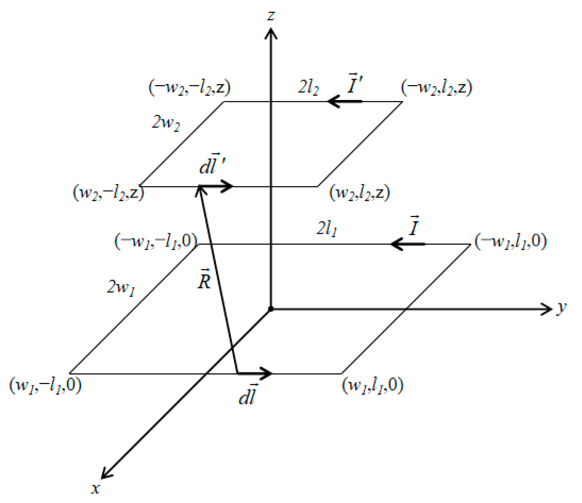
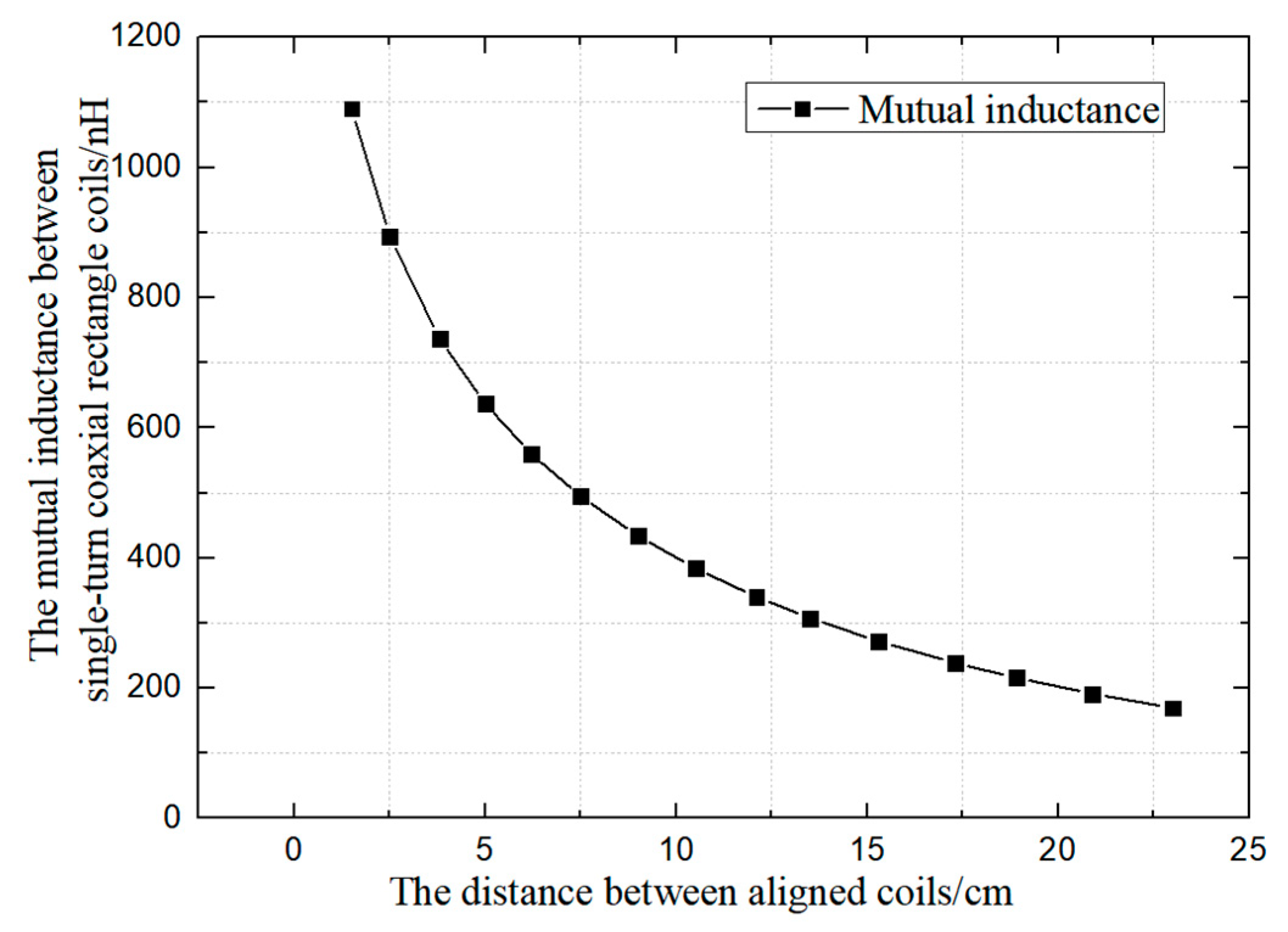
2.1. Mutual Inductance Calculation Based on Neumann Formula

In order to simplify analysis, the primary and secondary coils are regarded as several coaxial rectangle coils. The mutual inductance of each part is calculated based on the Neumann formula and then summed to obtain the mutual inductance between the primary and secondary coils in the case of alignment [23]. As shown in Figure 4, the lengths of the two coaxial rectangle coils are 2l1, 2l2, and the widths are 2w1, 2w2, respectively. The lower coil located on the xOy plane is at the primary side, and the upper coil is at the secondary side. The plane containing the secondary coil is parallel to the xOy plane and has a height of z. Select the line elements on the two coils respectively, assuming that the distance between the two line elements is R. According to the Neumann formula, it can be obtained that the mutual inductance between the two coils can be expressed as formula (1):
M = μ 0 4 π l l d l d l R
Let the line element coordinates of the primary side be (x1, y1, 0), and the line element coordinates of the secondary side be (x2, y2, z). Substituting the coordinates of the two line elements into formula (1) can be simplified as below:
d l d l = ( d x 2 , d y 2 , d z ) ( d x 1 , d y 1 , 0 ) = d x 1 d x 2 + d y 1 d y 2
It is assumed that the shape and the size of the primary and secondary coils are the same. In the Figure 4, w1 = w2 = w, l1 = l2 = l, then the mutual inductance of the single-turn coaxial equal-sized rectangle coil can be calculated by formula (3):
M = μ 0 w π ln 2 w + 4 w 2 + z 2 2 w + 4 w 2 + z 2 + μ 0 w π ln 2 w + 4 w 2 + 4 l 2 + z 2 2 w + 4 w 2 + 4 l 2 + z 2 + μ 0 l π ln 2 l + 4 l 2 + z 2 2 l + 4 l 2 + z 2 + μ 0 l π ln 2 l + 4 w 2 + 4 l 2 + z 2 2 l + 4 w 2 + 4 l 2 + z 2 + 2 μ 0 π ( z + 4 w 2 + 4 l 2 + z 2 4 w 2 + z 2 4 l 2 + z 2 )
According to the design requirements, substituting w = 200 mm and l = 300 mm into formula (3) can acquire the relationship between the mutual inductance and the distance between the coils when the single-turn coil is aligned, as shown in Figure 5.

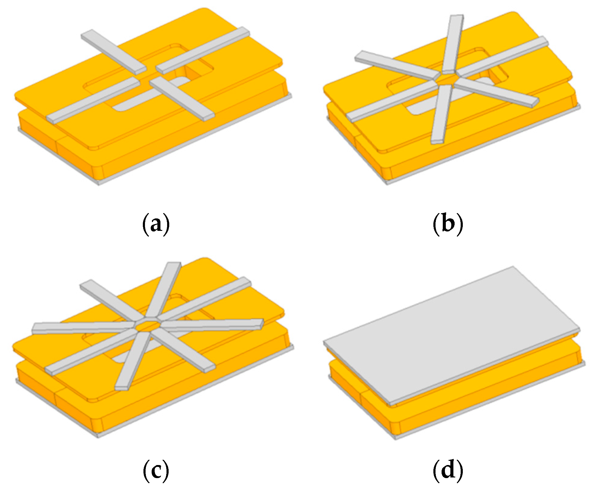
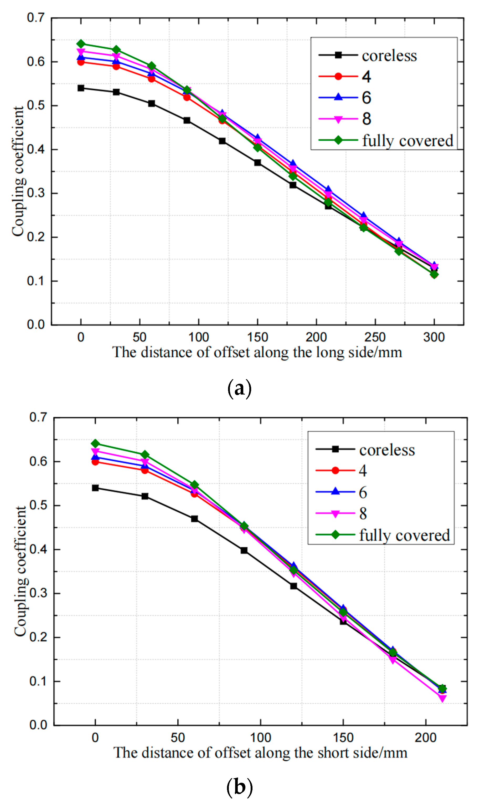
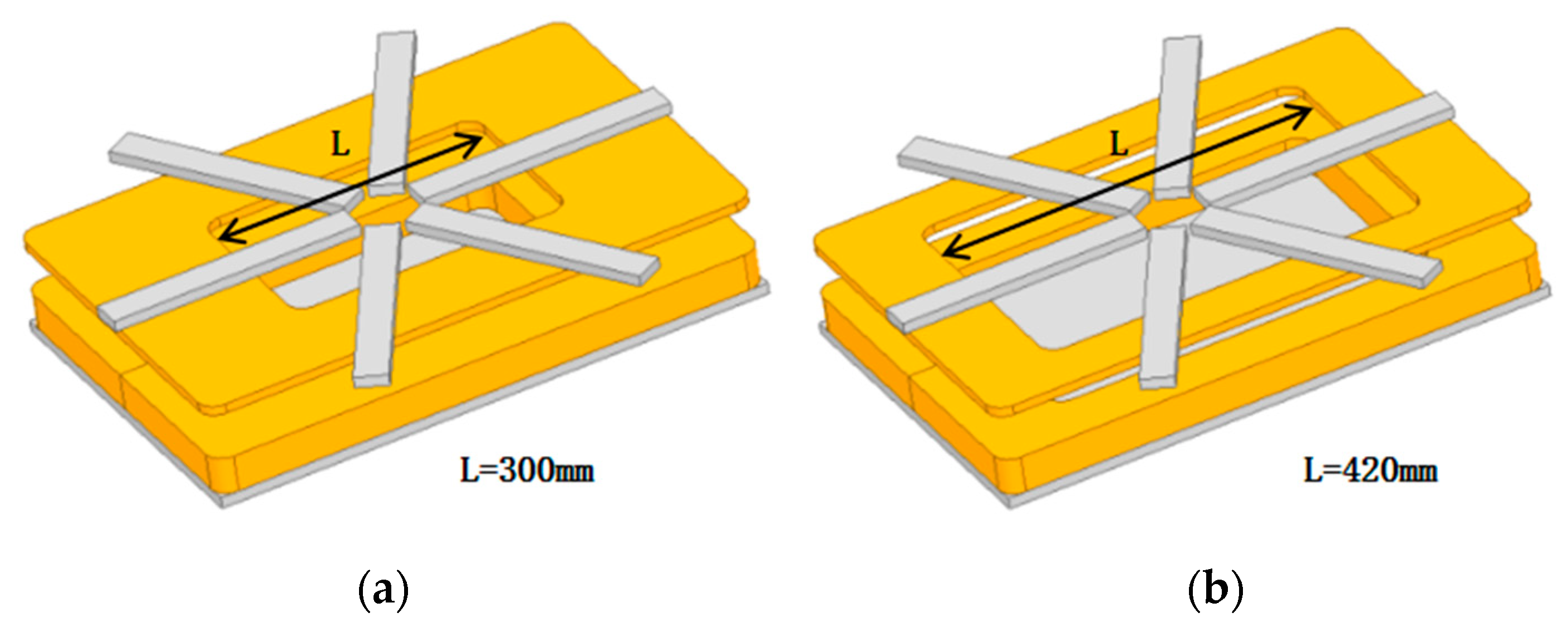
2.2. Core Distribution and Hole Size Optimization

The loosely coupled transformer designed in this paper adopts an asymmetric structure. Due to the few number of turns on secondary side, the secondary coil has a small self-inductance. Further, the resonant capacitor and inductor of the secondary side are reduced so that the secondary side of the system can be light and miniaturized, so this section focuses on the distribution of the cores and the optimization of the coil hole size [24,25]. At the same time, in this section, the optimization scheme is analyzed by combining the Neumann formula and the finite element simulation software Ansys Maxwell.
Due to the space and weight constraints, it is inappropriate to use fully covered magnetic cores on the secondary side although it has higher coupling coefficients. Considering the path of magnetic flux flow, the magnetic core is arranged in the pattern of radiation. Considering the limitations of forklift chassis space and corresponding coil size, the size of a single magnetic core was preliminary determined to be 35 mm × 300 mm × 12 mm. The magnetic cores on the primary side are fully laid under the primary side, while 4, 6, and 8 magnetic cores are respectively laid on the secondary side. The modeling procedure is shown in Figure 6.
The coupling coefficient at different offset positions can be obtained through simulation in Ansys Maxwell and the characteristic curve is shown in Figure 7. As the number of magnetic cores increases, the coupling coefficient between the coils also increases. As the increase of offset, the difference between coupling coefficients under different core scenarios tend to be reduce. When the offset reaches more than 100 mm, the coupling coefficient is approximately identical whether the magnetic cores are fully covered or radioactively distributed. According to the variation curve of offset distance-coupling coefficient, while considering that the secondary side should be light and miniaturized, the number of magnetic cores is finally determined to be 6. At this time, the coupling coefficient in the case of alignment is about 0.61, and the coupling coefficient is about 0.48 when the offset distance is 120 mm.
When the number of core strips is determined, the size of the coil hole, i.e., the ratio of the inner and outer diameters of the coil, will affect the anti-offset ability of the coil. In this design, the outer diameter of the coil is limited by the chassis size of the electric forklift, and is set to 400 mm × 600 mm as mentioned above. Figure 8 shows the simulation models of different coil hole sizes, where the holes have the same rectangular shape as the coil. Assume that the length of the long side of the hole is L, the length of the short side can be calculated as 400 L/600 according to the ratio. The simulation models with different hole sizes are respectively simulated to calculate the coupling coefficient in the case of alignment and misalignment, and the characteristic curve is drawn as shown in Figure 9.
When the size of the coil hole decreases, the coupling coefficient in the aligned situation is gradually increasing. When the size of the coil hole is smaller than a certain value, it can be considered that the coupling coefficients of the coil in the case of alignment are similar. On the other hand, when offset occurs, the larger the size of the coil hole is, the better anti-offset ability the coil has. Taking two factors above into consideration, the appropriate size of the coil hole is determined to be L = 300 mm, as it has higher coupling coefficient and better anti-offset ability at the same time. In the experiment, the outer size of the coil is 600 mm × 400 mm, with six magnetic core strips distributed radially, and the hole size is 300 mm × 200 mm. Finally, the actual measured coupling coefficient of the magnetic coupling mechanism in the case of alignment is 0.652, which is basically consistent with the simulation results.

3. Topology Design of WPT System with Constant Current Output

In order to compensate the reactive power in the system, it is necessary to add compensation module to the circuit, for example, increase the resonant capacitor to make the system more resistive so as to achieve the purpose of reducing the reactive power. In this section, according to the system requirement, the dual-LCL compensation which has the feature of constant current output is selected and analyzed. Then, the second-order compensation structure is optimized, and a resonant capacitor is added to form a more flexible dual-LCC compensation based on the dual-LCL system [26,27], which makes the system have higher transmission efficiency and transmission power.

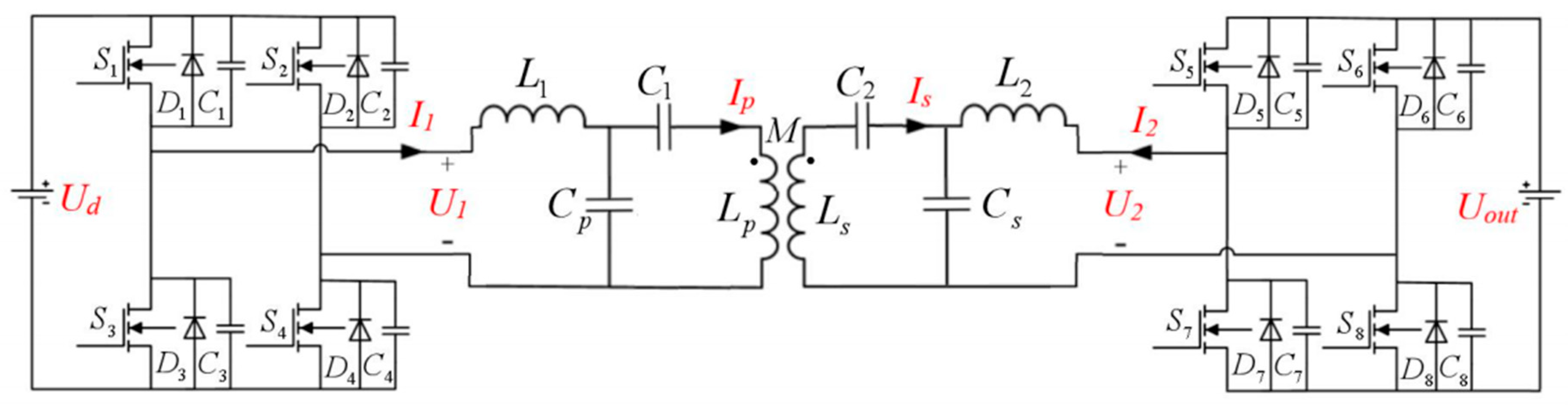
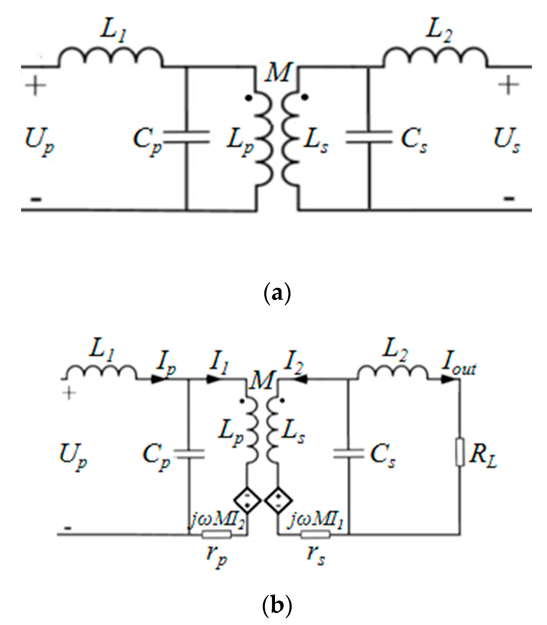
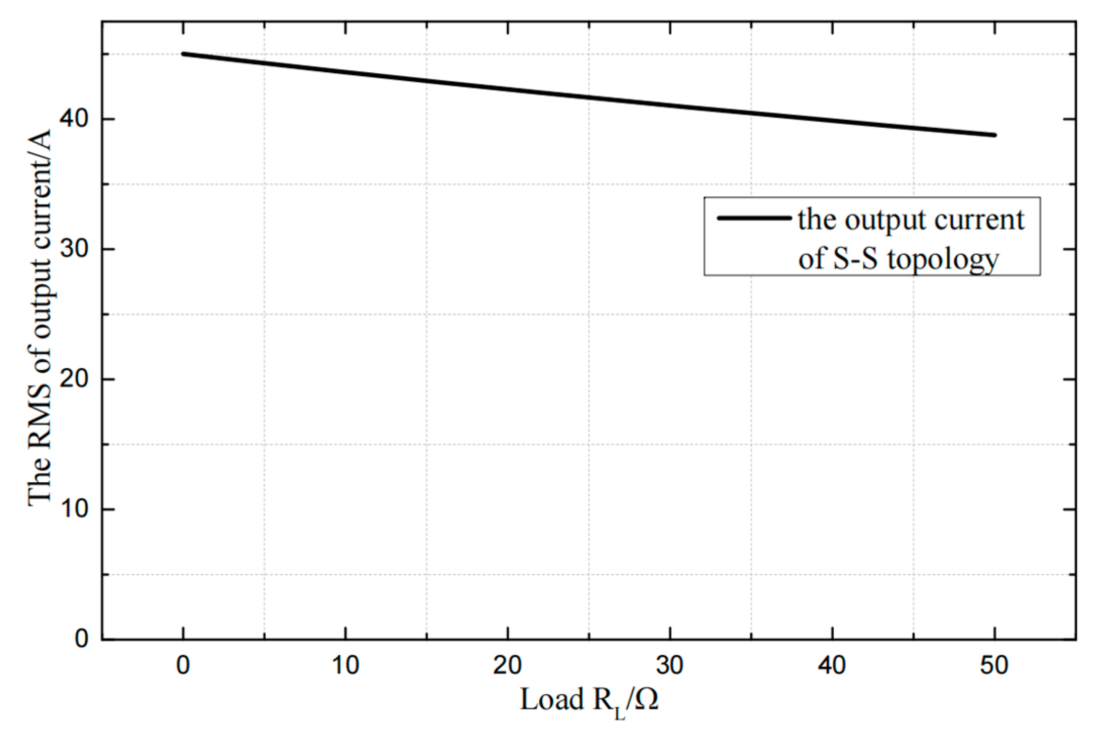
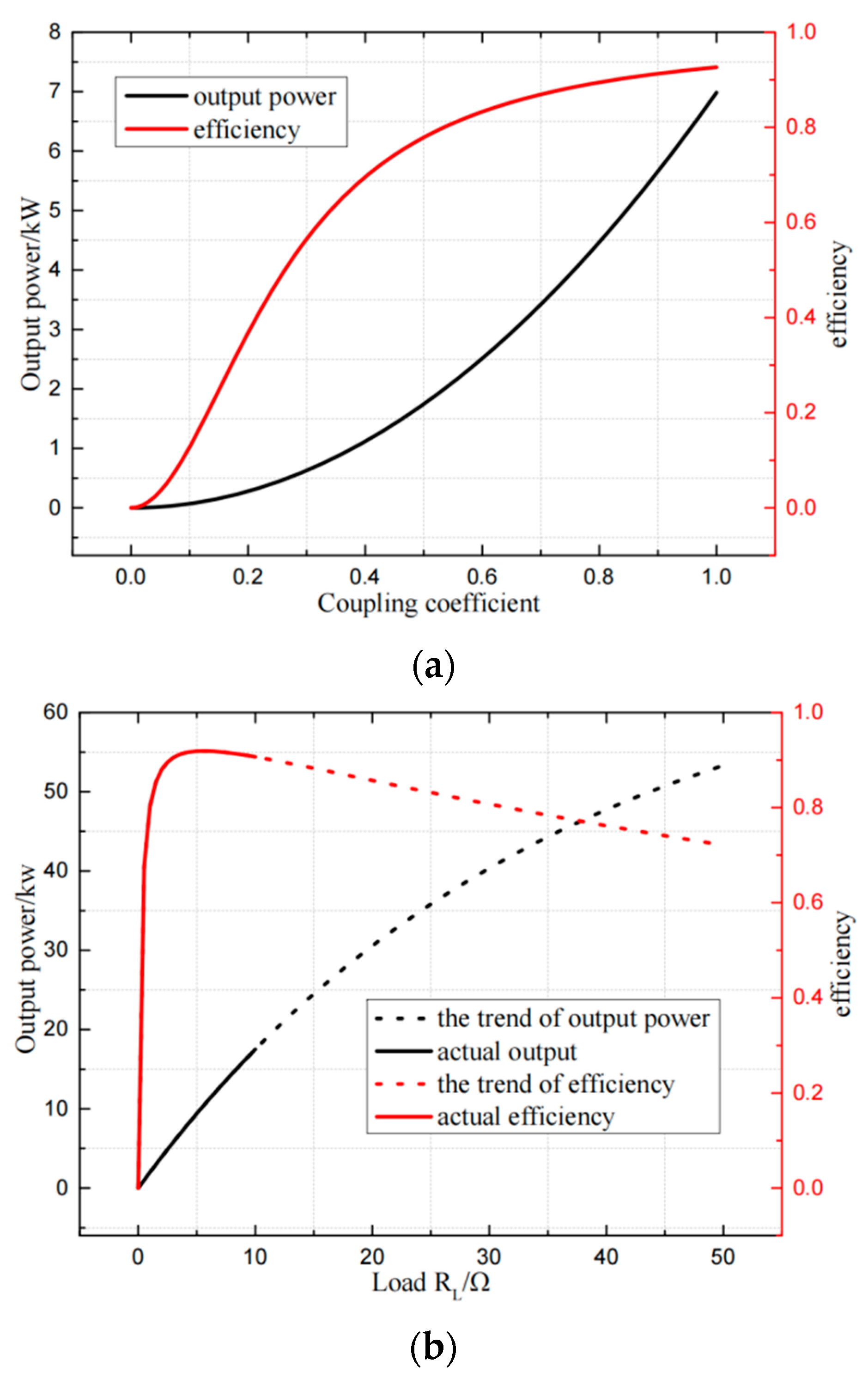
3.1. Dual-LCL Compensation Compensation and Analysis

The dual-LCL compensation model and equivalent circuit is shown in Figure 10a,b respectively. According to Figure 10b, the KVL loop equation of the equivalent circuit of dual-LCL compensation can be written as:
{ U p 1 = j ω L p I 1 + j ω M I 2 + r p I 1 j ω M 1 = I 2 ( j ω L s + r s + Z 1 )
where Z1 is the equivalent impedance including Cs, L2, RL:
Z 1 = ( j ω L 2 + R L ) / / 1 j ω C s = ( j ω L 2 + R L ) 1 j ω C s j ω L 2 + R L + 1 j ω C s
According to Formulas (4) and (5), in order to ensure constant current output of the system and the resistive input impedance, the parameters of resonant elements need to conform to Formula (6):
{ j ω L s + 1 j ω C s = j ω L 2 + 1 j ω C s = 0 j ω L p + 1 j ω C p = j ω L 1 + 1 j ω C p = 0
It can be further obtained that when the system works at the resonant operating point, the output current of the system is:
I o u t = M U p ( ω 2 L 2 2 + R L r s ) j ω C s L p
According to Formula (7), if the resistance of the coil is ignored, the RMS value of the output current can be rewritten as Formula (8):
I o u t = M U p ω L p L s = k U p ω L p L s
Once the coupling coefficient is determined, the output current is only related to the coils self-inductance of the primary and secondary side. In order to draw the transmission curve of the dual-LCL compensation, the self-inductance of the primary and secondary coils are set the same tentatively. The value of inductance is 6.81 μH, the value of resonant capacitance is 529.5 nF, and the coil resistance is 0.1 Ω. As shown in Figure 11, it can be seen that the output current is basically constant, and it slowly decreases as the load increases, which is caused by the internal resistance of the coil.
The output power and efficiency of the system are further obtained by formula (9)–(11) as follows:
P out = ω 2 L 2 3 k 2 U p 2 ( ω 2 L 2 2 + R L r s ) 2 L p R L
η = N k 2 ω 2 L p L s r p r s k 2 + ω 2 L 2 2 R L r s + 1
Inside
N = ω 4 L 2 3 L p R L ω 2 L 2 2 + R L r s
Considering the existence of offset and the change of the load, the curves of coupling coefficient, load-power and efficiency are drawn as shown in Figure 12 below:
The dual-LCL compensation has a strong anti-offset ability. As shown in Figure 12a, the transmission power and efficiency of the system increase with the increase of the coupling coefficient. When the coupling coefficient is 0.652, the output power of the system reaches 3 kW with an efficiency of 85%. The curve is relatively smooth, and it is relatively easy to adjust when the offset is within a certain range. According to Figure 12b, because the topology has constant current output feature, when the coupling coefficient remains unchanged, the change of the load does not affect the output current. So, the system output power is approximately proportional to the load resistance. However, adopting this scheme will make the inductance of the primary and secondary coils small, only at the level of 10−6 H. As a result, the coils only have few turns. Not only will the coupling coefficient between the coils be affected, but the voltage drop between turns will be too large. The transmission characteristics of the system will be affected because the parasitic capacitance exists. In order to make the system stable, it is necessary to further optimize the topology on the basis of the dual-LCL compensation.

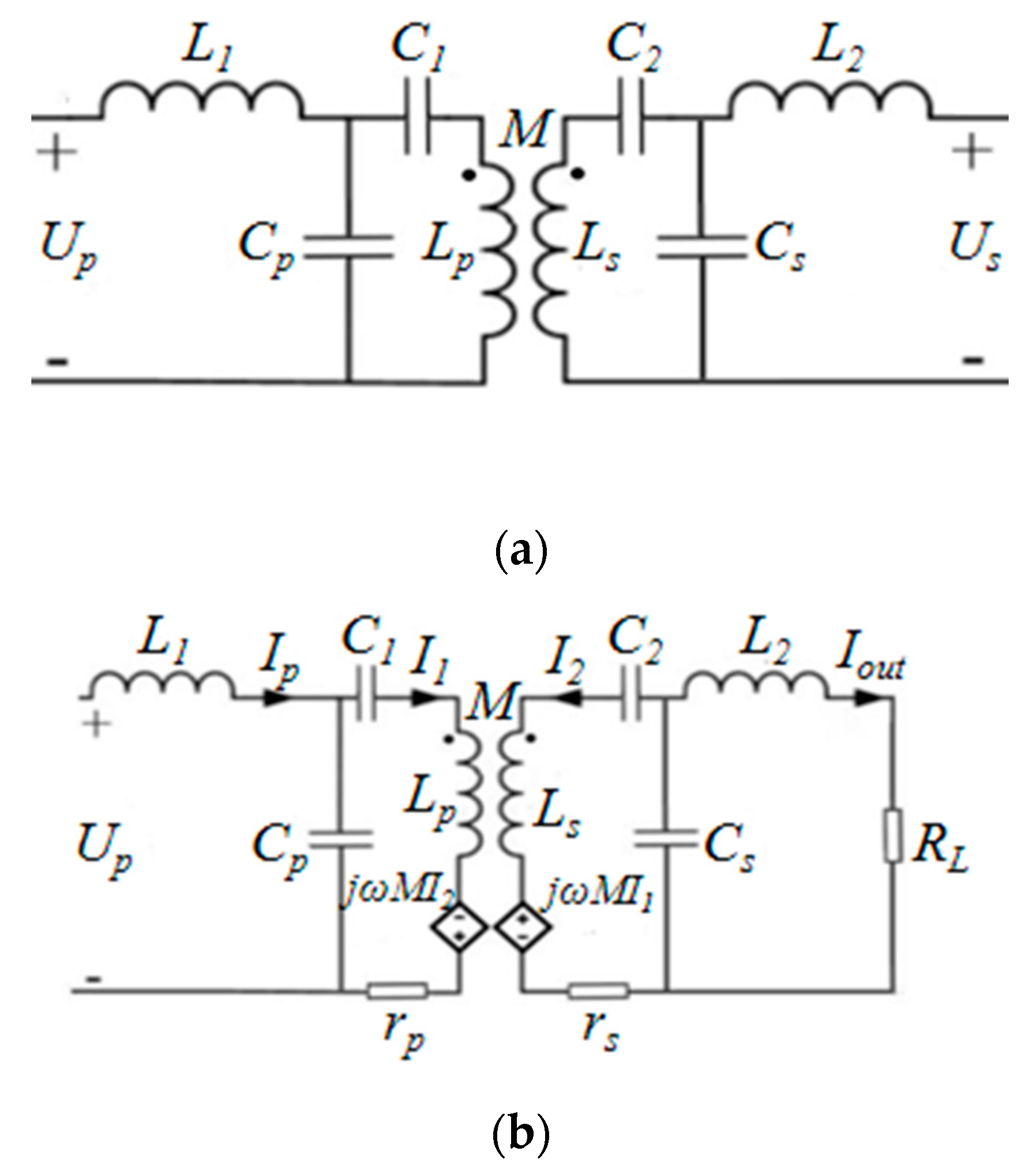
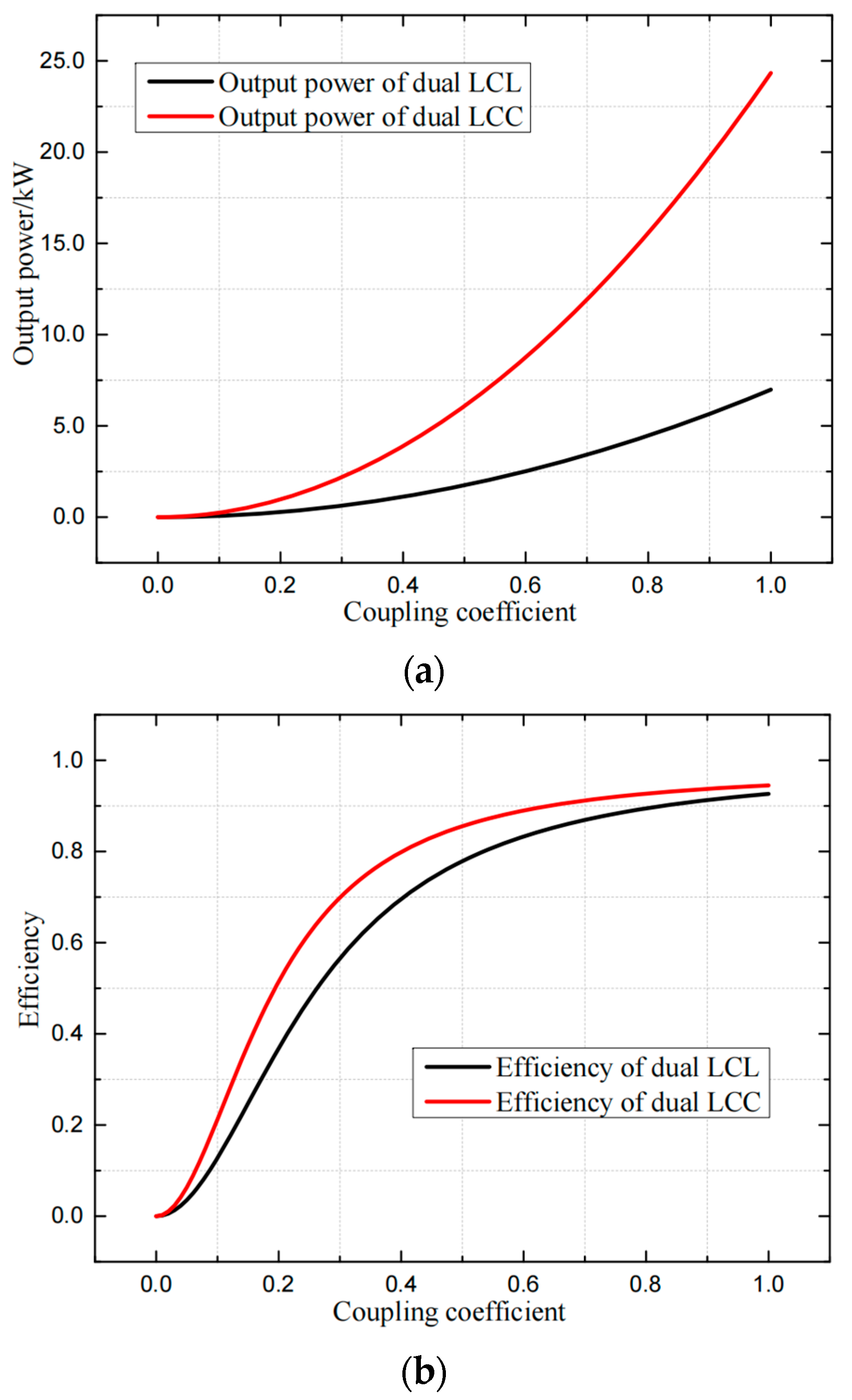
3.2. The Optimization and Improvement of Dual LCL-Dual LCC Compensation

Although the dual-LCL compensation has the ability of anti-offset and anti-load variations, its output power cannot reach a high level due to the limitation of coil inductance. Ideally, the resistance of the coil is ignored. According to formula (4)–(11) it can be deduced that the output current is:
I o u t = ω M U p j ω 2 L 1 L 2
when the size of the coil, the method of winding, and the distribution of the magnetic core are determined, the self-inductance and mutual inductance of the primary and secondary coils will no longer change. For the dual-LCL compensation, both the primary and secondary sides need to work at the resonant point, that is, L1 = Lp, L2 = Ls, so the value of the output current will be limited. Therefore, in order to further improve the transmission power of the system, a resonant capacitor can be connected in series with each of the primary and secondary coils to form a dual-LCC structure to compensate the inductance of the coil, as shown in Figure 13 below:
By increasing the capacitance of the added capacitor, the values of L1 and L2 can be changed. In order to satisfy the constant current output of the system and the soft switching characteristics, formula (6) should be modified as:
j ω L s + 1 j ω C 2 + 1 j ω C s = j ω L 2 + 1 j ω C s = 0
j ω L p + 1 j ω C 1 + 1 j ω C p = j ω L 1 + 1 j ω C p = 0
According to the formula above, the output current can be adjusted to a larger value when the values of L1 and L2 change. In order to compare the maximum output power and efficiency characteristics of two compensations, the output power, system efficiency-coupling coefficient characteristic curves of the dual-LCL compensation and the dual-LCC compensation are drawn and shown in Figure 14.
It can be seen from Figure 14 that the dual-LCC compensation achieves a larger output current and output power. On the other hand, due to the additional resonant capacitor, the current flowing through the coil can be reduced by adjusting the parameters. The loss on the wire will be reduced, and the efficiency of the system will increase. As shown in Figure 14b, when the coupling coefficient is in the range of 0.2 to 0.6, the dual-LCC compensation has a significantly higher system efficiency.

3.3. Optimization of Dual-LCC Asymmetric Loosely Coupled Transformer

In the existing research on dual-LCC compensation, only the system transmission power and transmission efficiency are analyzed and discussed. Because of the complex mathematical model, there is rarely a detailed analysis of its parameter selection. This section compares the asymmetric and symmetric parameters of the loosely coupled mechanism, and then analyzes the influence on the transmission power and efficiency of the system. By optimizing the parameters of the asymmetric loosely coupled mechanism, the system can achieve higher transmission power and efficiency meanwhile reducing the voltage and current stress of devices to save cost and size.
Assume that the symmetric and asymmetric loosely coupled mechanisms have the same coupling coefficient and mutual inductance. For the symmetrical parameters, the primary and secondary side parameters are completely equal. For the asymmetrical parameters, when the value of mutual inductance is determined, the self-inductance of the primary and secondary coils can be unequal. Based on the actual value of mutual inductance, the parameters of the circuit can be obtained as shown in Table 2.
In terms of the parameters in the Table 1 and the formula (20), the output current is similar whether the parameters are symmetrical or asymmetrical. The influence of the coupling coefficient and the load on the transmission efficiency and power of the system under the symmetrical and asymmetrical parameters is analyzed below.
For the coil, its inductance is proportional to the square of the number of turns and its resistance is proportional to the number of turns. According to the parameters in Table 1, the characteristic curve of the transmission power of the coupling coefficient and the load can be obtained as shown in Figure 15.
It can be seen from Figure 15a that in the case of asymmetrical parameters, the transmission power is slightly larger than that of symmetric parameters. It can be seen in Figure 15b that the transmission power of the asymmetrical parameter is slightly larger than that of the symmetrical parameter under different loads. Therefore, optimizing the parameters of the loosely coupled mechanism to obtain asymmetrical parameters can increase the transmission power of the system to a certain extent.
It can be seen from Figure 16a that the system efficiency of asymmetrical parameters is slightly larger than that of symmetric parameters when the coupling coefficient is small. It can be seen from Figure 16b that the system transmission efficiency under asymmetrical parameters is slightly higher when the load is small. To sum up, the system with asymmetrical parameters has higher transmission efficiency and power than the symmetrical parameter in some cases, so the dual-LCC compensation with the asymmetrical loose coupling mechanism is adopted in this system.

4. Phase Shift Control of Dual-LCC Wireless Power Transfer System

In order to analyze the phase-shift control strategy in the dual-LCC WPT system, it is necessary to establish the equivalent model of the two-port network of the transmission system first. The relationship between the voltage and current at both ends should be obtained, so as to analyze how to control the system through the phase-shift angle [28,29]. The circuit model of the dual-LCC compensation is shown in Figure 17.
The expression of the transmission parameter equation is as follows:
{ U ˙ 1 = A U ˙ 2 + B ( I ˙ 2 ) I ˙ 1 = C U ˙ 2 + D ( I ˙ 2 )
In order to calculate the transmission parameters, it is necessary to calculate the case of open circuit and short circuit on the right side respectively, that is, make I2 = 0, U2 = 0 respectively:
{ A = U ˙ 1 U ˙ 2 | I ˙ 2 = 0 C = I ˙ 1 U ˙ 2 | I ˙ 2 = 0 { B = U ˙ 1 I ˙ 2 | U ˙ 2 = 0 D = I ˙ 1 I ˙ 2 | U ˙ 2 = 0
In order to achieve constant current output and to achieve soft switching of the circuit, the parameters of the resonant inductor and capacitor should conform the formula (17):
{ j ω L p + 1 j ω C 1 = j ω L 1 j ω L s + 1 j ω C 2 = j ω L 2 1 ω 2 L 1 C p = 0 1 ω 2 L 2 C s = 0
Substituting the formula above into formula (15)–(17), the transmission parameters of the system can be obtained as follows:
{ A = 0 B = j ω L 1 j ω L 2 j ω M C = j ω M j ω C p j ω C s D = 0
Therefore, the current and voltage across the two ports have the following relationship:
{ U ˙ 1 = j ω L 1 j ω L 2 j ω M ( I ˙ 2 ) I ˙ 1 = j ω M j ω C p j ω C s U ˙ 2
From the above formula, it can be obtained that I1 leads U2 by 90°, and I2 leads U1 by 90°. The relationship between the output current and the phase shift angle is as the following:
It can be seen from Figure 18 that the output current increases first and then decreases with the increase of the phase shift angle, and the output current reaches the maximum value when the phase shift angle is π/2, so the magnitude of the output current can be changed by controlling the value of the phase shift angle.
As shown in Figure 19, by sampling the output current on the secondary side, the maximum value of the output current and the phase difference between the primary and secondary sides can be obtained according to the sampled current without communication. The drive signal of secondary synchronous rectification is further controlled by a given current reference value, and the phase shift angle and the duty cycle of the drive signal are changed to achieve the purpose that the system maintains constant current output when interference exists.

5. Verification of Asymmetric Loosely Coupled Transformer WPT System

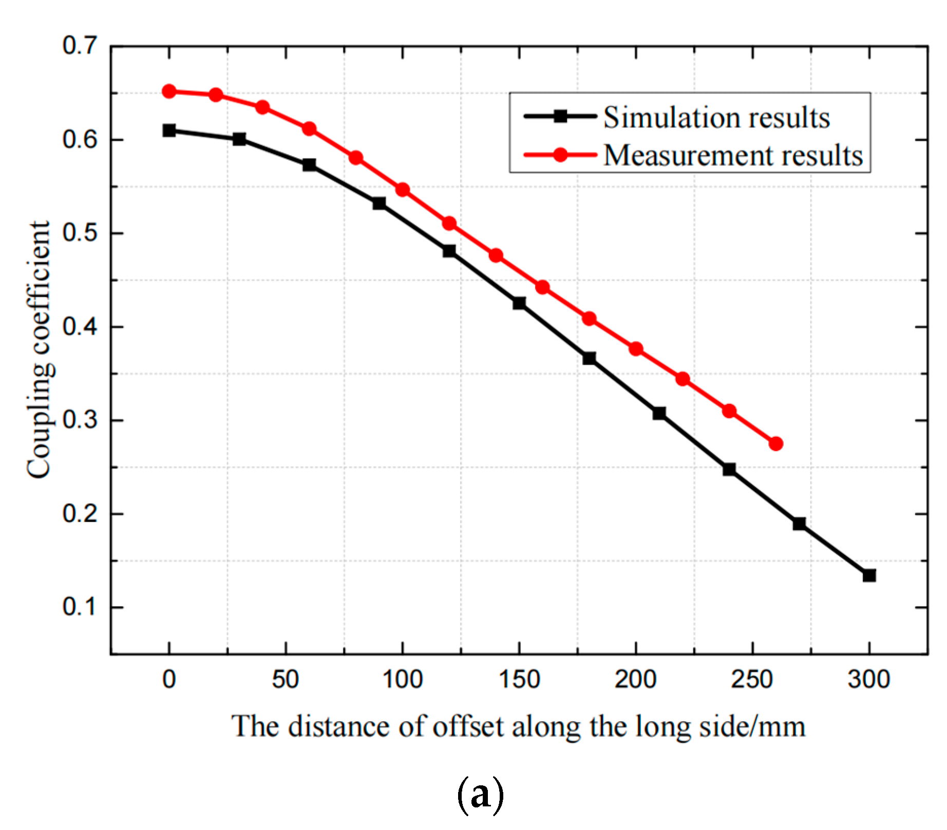
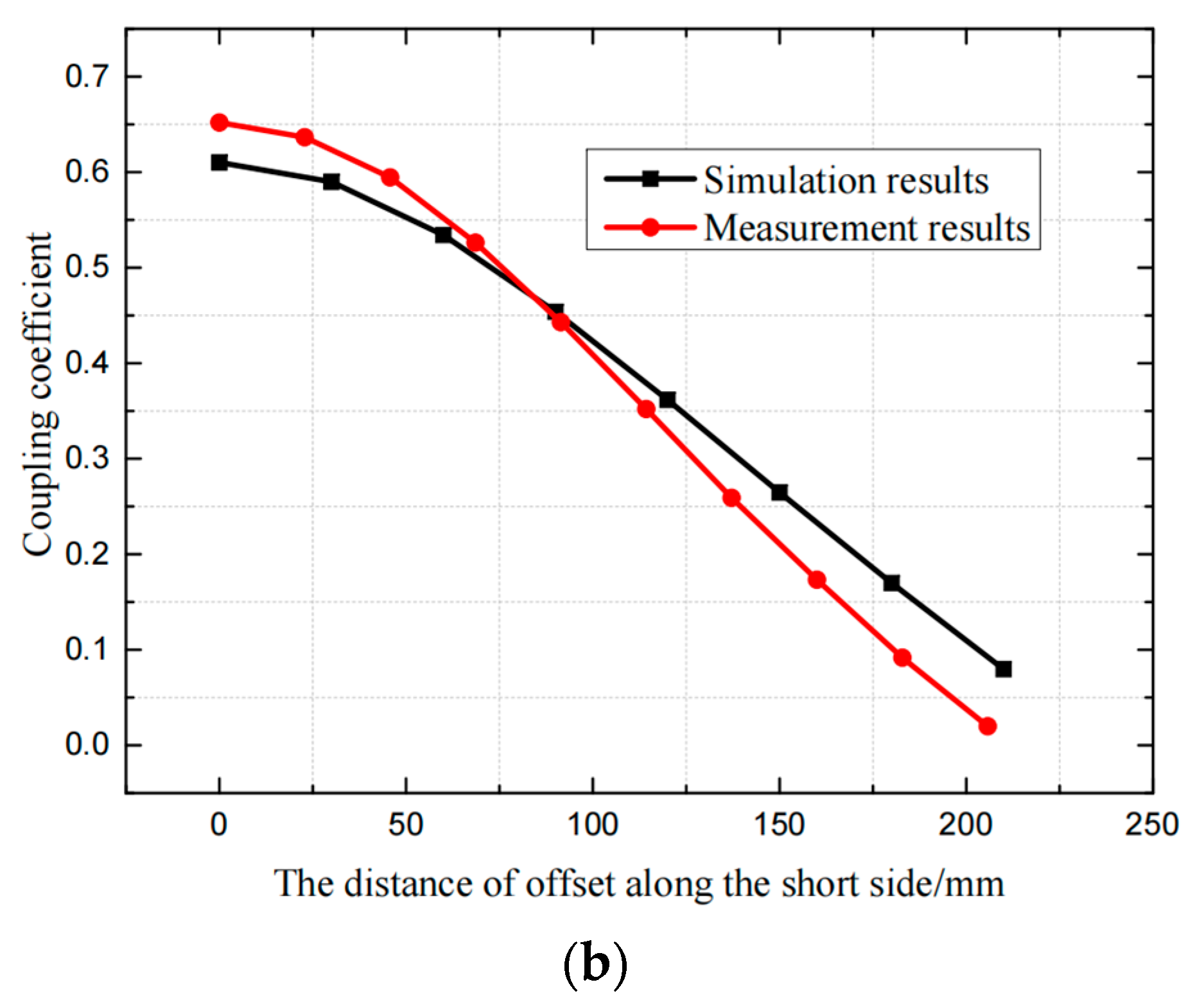
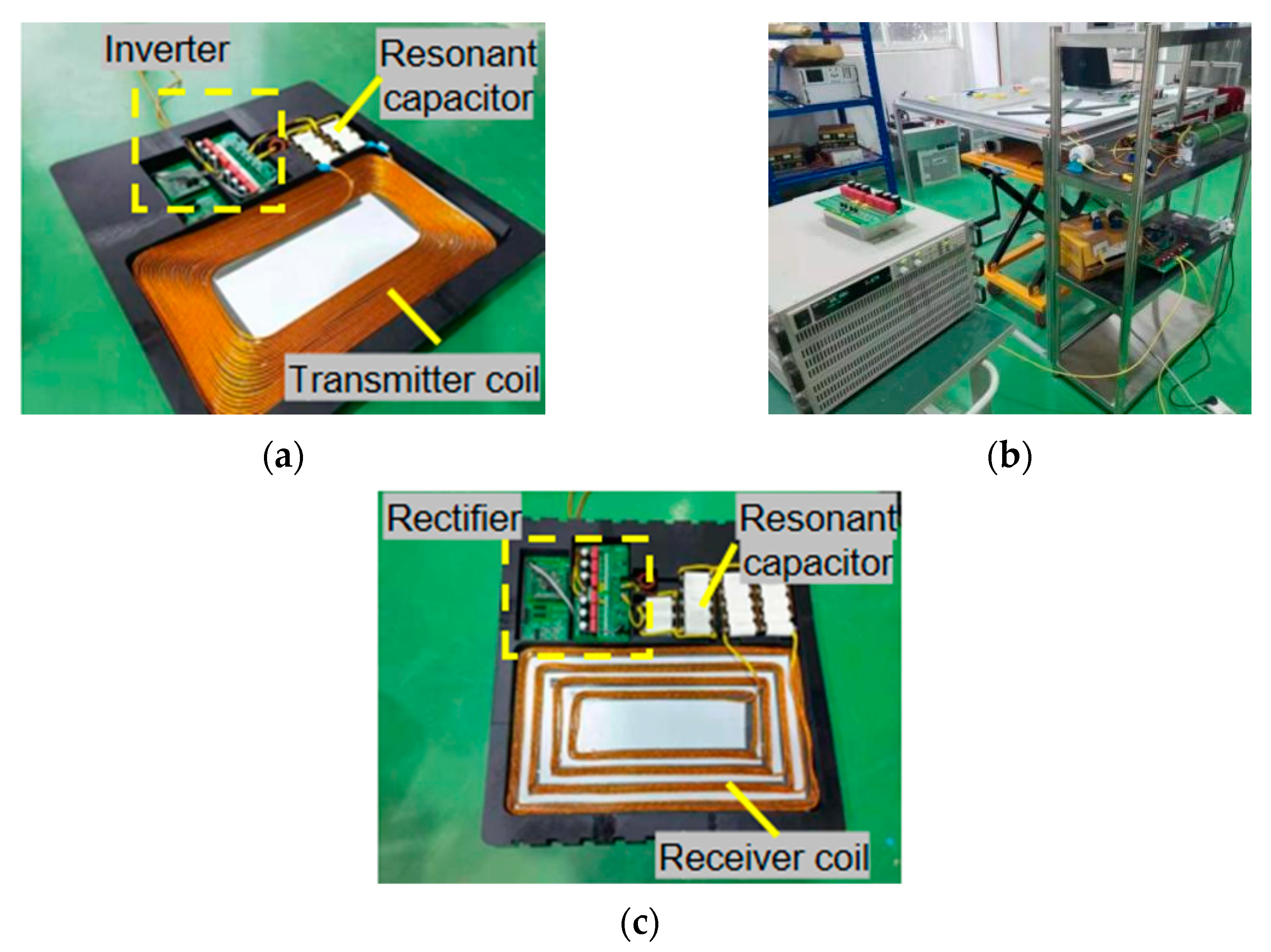
5.1. Winding and Verification of Asymmetric Magnetic Coupling Mechanism

The coils wound according to Chapter II and are shown in Figure 20. Figure 20a,b show the distribution of the primary, secondary coils and magnetic cores of the magnetic coupling mechanism respectively. The primary and secondary sides are wound as rectangle coils with the size of 400 mm × 600 mm, and the size of the holes is 200 mm × 300 mm.
As shown in Figure 21, when the distance between primary and secondary coils is less than 5 cm, the theoretical calculation value is basically consistent with the value of actual measurement. When this distance increases, there is a small gap between theoretical calculation and actual measurement.
As shown in Figure 22, it can be seen that the measured results are basically consistent with the simulation results. When the coils are aligned, the measured coupling coefficient is about 0.652 and the simulated coupling coefficient is 0.61. When the coils are misaligned, both measurement and simulation have the same downward trend and similar values. In the subsequent experiments, the parameters of other resonant elements are adjusted based on the measured value of the coil, so that the system could reach the predetermined output value.

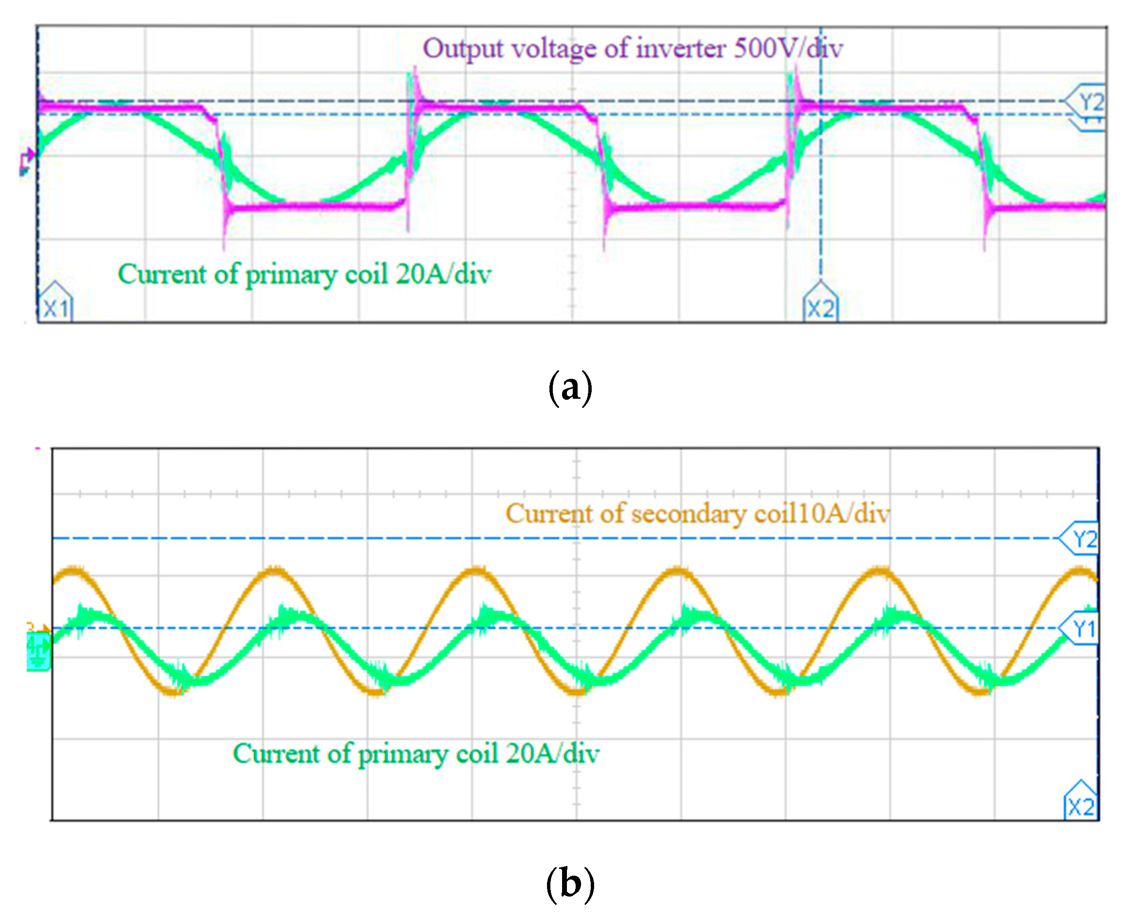
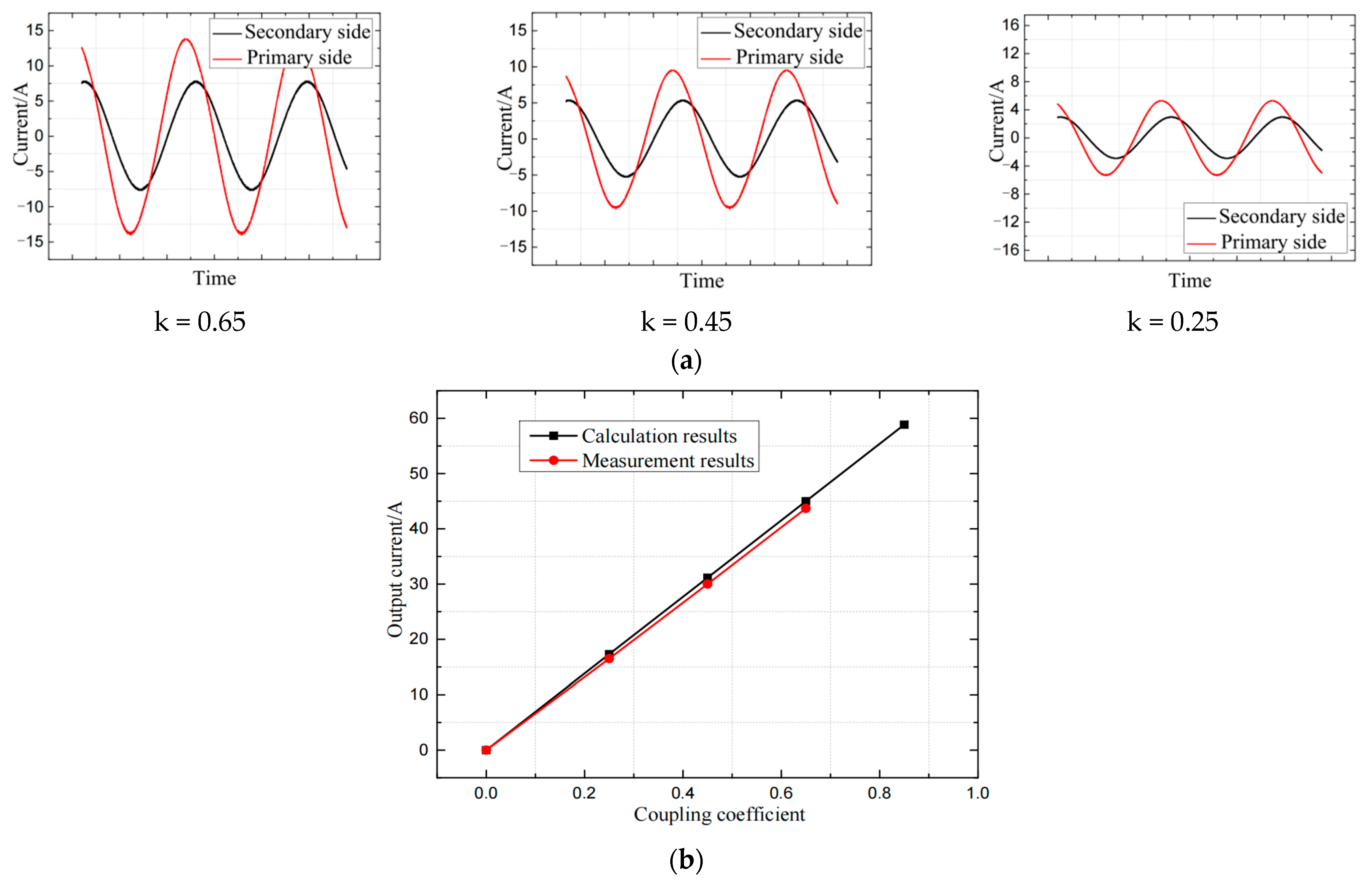
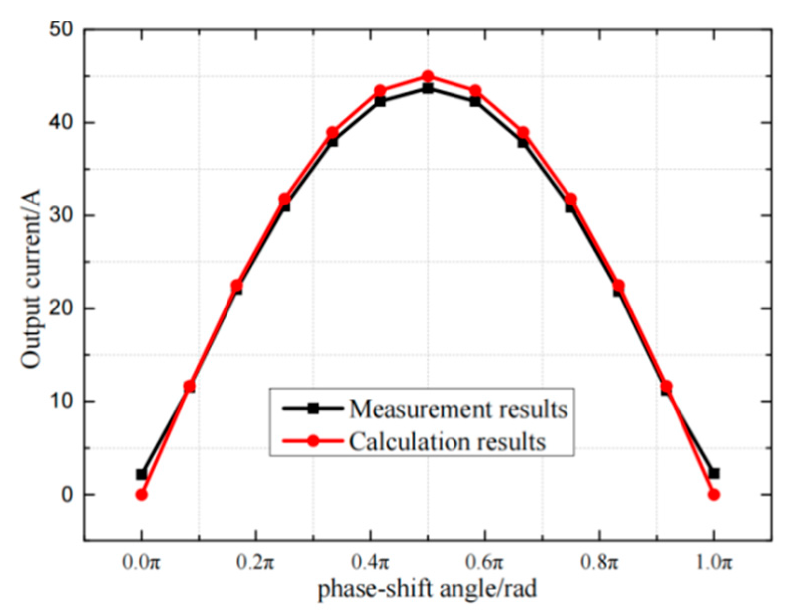
5.2. Wireless Power Transfer System Verification

In order to verify the asymmetrical magnetic coupling mechanism and constant current output characteristics of the WPT system proposed in this paper, the experimental platform is set up as shown in Figure 23c. In order to verify the constant current output charging characteristics of the system, the transmitter and receiver are packaged according to the actual size of the electric forklift, as shown in Figure 23a,b. According to the actual parameters of the magnetic coupling mechanism in Chapter V and the analysis in Chapter II, the parameters in the circuit can be listed as shown in Table 3.
According to the parameters listed above, the experimental waveforms are shown in Figure 24. The purple waveform in Figure 24a is the inverter output voltage, the green waveform in Figure 24a is the current in the primary coil. The green waveform in Figure 24b is the current in the primary coil while the orange waveform is the current in the secondary coil. The blue and purple waveforms in Figure 24c are the driving waveforms, and the amplitude of rectangle wave is 5 V. The green signal is that the peak-to-peak value of the current flowing in the secondary coil is about 14 A. Since this topology has a large impedance to harmonic components, there is only the fundamental component and the noise caused by switching in the secondary coil. The orange signal is the output voltage of load, and is about 68.4 V. The output current is 43.7 A, then the output power can be calculated as 2.99 kW, the input voltage of DC bus is 280 V, and the input current is 11.7 A, the input power is 3.276 kW, and the transmission efficiency is 91.2%.
At the same time, in order to verify the influence on the transmission characteristics caused by the change of the coupling coefficient when the offset exists, the output current was measured with different distances of offset. The results are then compared with the theoretical calculations as shown in Figure 25.
As shown in Figure 25a, when the coupling coefficient decreases, the current of the primary and secondary coils gradually decreases. As shown in Figure 25b, when the coils are aligned, the theoretically calculated output current value is 45 A while the measured value is 43.7 A. As the offset between the coils becomes larger, the coupling coefficient between the coils gradually decreases, and the output current decreases linearly with the decrease of the coupling coefficient.
As shown in Figure 26, in the actual test, when the coupling coefficient is 0.652, the output power value of the system can reach 2.99 kW, which is basically consistent with the theoretical value mentioned above, and the transmission power-coupling coefficient characteristic curve trend is consistent.
As shown in Figure 27, in the actual test, when the load changes within a certain range, the output current is basically constant and is about 44 A. The measured value and the calculated value have the same trend, but the measured value is slightly lower than the calculated value. This may be due to the presence of resistance in the actual circuit.
In order to verify the relationship between the phase-shift angle and the output current in Chapter IV, the phase-shift angle of the synchronous rectifier in the secondary side was changed, and the output current is measured under different phase-shift angles. The curve between output current and the phase-shift angle is shown in Figure 28. When the secondary side control signal lags the primary side control signal by 90°, the secondary side output current reaches the maximum value. The relationship between output current and phase-shift angle is approximated to a sine function and the theoretical calculated value is basically consistent with the measured value, which proves the feasibility of the control scheme.

6. Conclusions

This paper takes the electric forklift charging as the application background, and conducts research on the design and optimization of the wireless power transmission system. An asymmetric loosely coupled transformer which is suitable for short distance and high power is designed, and the transmission topology is designed and optimized with the goal of constant current charging. The specific work is summarized as follows: First, the coil mutual inductance model is theoretically analyzed according to the Neumann formula, and the magnetic core distribution and coil structure are further optimized by using the finite element simulation software and the Neumann formula, so that the magnetic coupling mechanism have a better anti-offset ability while maintaining an appropriate coupling coefficient. The theory is verified by actually winding the optimized coil and testing, and the magnetic coupling mechanism have a coupling coefficient of 0.652 in the case of alignment. Second, it is analyzed that the dual-LCL compensation cannot achieve higher output power and efficiency under the limitation of the magnetic coupling mechanism parameters, and an additional resonant element are added to form the dual-LCC compensation which can achieve higher output power and efficiency. By analyzing and comparing the dual-LCC compensation of symmetric parameters and asymmetric parameters, the parameters are optimized to further improve the power and efficiency of the system. Then, a communication-free control method is proposed to make the output achieve the system requirements by controlling the phase shift angle. Finally, an experimental platform is built and the theory is verified. The system applies the optimized magnetic coupling mechanism and dual-LCC topology. The final system can achieve 3 kW output power and 45 A constant output current with 91.2% transmission efficiency. For future research, it can be further considered to adjust the system parameters and control methods so that the system can realize the transition from constant current charging to constant voltage charging.

Author Contributions

Conceptualization, J.Z., X.L. and A.Y.; methodology, J.Z. and X.L.; validation, J.Z., X.L. and J.G.; formal analysis, J.Z. and X.L.; investigation, J.G. and A.Y.; resources, A.Y. and J.Z.; writing—original draft preparation, J.Z. and X.L.; writing—review and editing, J.Z.; supervision, Q.L.; project administration, J.Z. All authors have read and agreed to the published version of the manuscript.

Funding

This research was funded by Natural Science Foundation of Zhejiang Province (LY21E050001).

Institutional Review Board Statement

Not applicable.

Conflicts of Interest

The authors declare no conflict of interest.

References

  1. Li, S.; Li, W.; Deng, J.; Nguyen, T.D.; Mi, C.C. A Double-Sided LCC Compensation Network and Its Tuning Method for Wireless Power Transfer. IEEE Trans. Veh. Technol. 2015, 64, 2261–2273. [Google Scholar] [CrossRef]
  2. Lee, S.; Choi, B.; Rim, C.T. Dynamics characterization of the inductive power transfer system for online electric vehicles by Laplace phasor transform. IEEE Trans. Power Electron. 2013, 28, 5902–5909. [Google Scholar] [CrossRef]
  3. Sato, M.; Yamamoto, G.; Gunji, D.; Imura, T.; Fujimoto, H. Development of Wireless In-Wheel Motor Using Magnetic Resonance Coupling. IEEE Trans. Power Electron. 2016, 31, 5270–5278. [Google Scholar] [CrossRef]
  4. Choi, S.Y.; Gu, B.W.; Jeong, S.Y.; Rim, C.T. Advances in Wireless Power Transfer Systems for Roadway-Powered Electric Vehicles. IEEE J. Emerg. Sel. Top. Power Electron. 2015, 3, 18–36. [Google Scholar] [CrossRef]
  5. Chai, R.; Zhang, Y. A Practical Supercapacitor Model for Power Management in Wireless Sensor Nodes. IEEE Trans. Power Electron. 2015, 30, 6720–6730. [Google Scholar] [CrossRef]
  6. Li, H.; Li, J.; Wang, K.; Chen, W.; Yang, X. A Maximum Efficiency Point Tracking Control Scheme for Wireless Power Transfer Systems Using Magnetic Resonant Coupling. IEEE Trans. Power Electron. 2015, 30, 3998–4008. [Google Scholar] [CrossRef]
  7. Mcdonough, M. Integration of inductively coupled power transfer and hybrid energy storage system: A multi-port power electronics interface for battery powered electric vehicles. IEEE Trans. Power Electron. 2015, 30, 6423–6433. [Google Scholar] [CrossRef]
  8. Hiramatsu, T.; Huang, X.; Kato, M.; Imura, T.; Hori, Y. Wireless charging power control for HESS through receiver side voltage control. In Proceedings of the 2015 IEEE Applied Power Electronics Conference and Exposition (APEC), Charlotte, NC, USA, 15–19 March 2015; pp. 1614–1619. [Google Scholar]
  9. Ahmad, A.; Alam, M.S.; Chabaan, R. A comprehensive review of wireless charging technologies for electric vehicles. IEEE Trans. Transp. Electrif. 2018, 4, 38–63. [Google Scholar] [CrossRef]
  10. Li, Y.L.; Sun, Y.; Dai, X. Robust control for an uncertain LCL resonant ICPT system using LMI method. Control. Eng. Pract. 2013, 21, 31–41. [Google Scholar] [CrossRef]
  11. Tan, L.; Li, J.; Wei, B.; Wang, S.; Huang, X.; Liu, H.; Tang, Z. Research on Middle-Distance Wireless Power Transmission Systems Based on Electromagnetic Metamaterial. In Proceedings of the 2019 IEEE 2nd International Conference on Electronics Technology (ICET), Chengdu, China, 10–13 May 2019; pp. 464–467. [Google Scholar]
  12. Chen, W.; Chen, Q.; Huang, J.; Zhang, H. Analysis and Research of Distance Transmission Characteristics of Magnetic Resonance WPT System. In Proceedings of the 2014 IEEE 79th Vehicular Technology Conference (VTC Spring), Seoul, Korea, 18–21 May 2014; pp. 1–5. [Google Scholar]
  13. Cheng, C.; Lu, F.; Zhou, Z.; Li, W.; Zhu, C.; Zhang, H.; Deng, Z.; Chen, X.; Mi, C.C. Load-Independent Wireless Power Transfer System for Multiple Loads Over a Long Distance. IEEE Trans. Power Electron. 2019, 34, 9279–9288. [Google Scholar] [CrossRef]
  14. Zhang, Y.; Wang, L.; Guo, Y.; Tao, C. Null-Coupled Magnetic Integration for EV Wireless Power Transfer System. IEEE Trans. Transp. Electrif. 2019, 5, 968–976. [Google Scholar] [CrossRef]
  15. Lu, F.; Zhang, H.; Hofmann, H.; Mi, C. A dynamic charging system with reduced output power pulsation for electric vehicles. IEEE Trans. Ind. Electron. 2016, 63, 6580–6590. [Google Scholar] [CrossRef]
  16. Chen, Y.; Zhang, H.; Shin, C.-S.; Jo, C.-H.; Park, S.-J.; Kim, D.-H. An Efficiency Optimization-Based Asymmetric Tuning Method of Double-Sided LCC Compensated WPT System for Electric Vehicles. IEEE Trans. Power Electron. 2020, 35, 11475–11487. [Google Scholar] [CrossRef]
  17. Li, S.; Guo, Y.; Tao, C.; Li, F.; Wang, L.; Bo, Q. Analysis of the input impedance of the rectifier and design of LCC compensation network of the dynamic wireless power transfer system. IET Power Electron. 2019, 12, 2678–2687. [Google Scholar] [CrossRef]
  18. Zhang, X.; Kan, T.; You, C.; Mi, C. Modeling and Analysis of AC Output Power Factor for Wireless Chargers in Electric Vehicles. IEEE Trans. Power Electron. 2016, 32, 1481–1492. [Google Scholar] [CrossRef]
  19. Lu, F.; Zhang, H.; Hofmann, H.; Mi, C. A high efficiency 3.3 kW loosely-coupled wireless power transfer system without magnetic material. In Proceedings of the 2015 IEEE Energy Conversion Congress and Exposition (ECCE), Montreal, QC, Canada, 20–24 September 2015; pp. 2282–2286. [Google Scholar]
  20. He, G.; Chen, Q.; Xin, P.; Chen, X. Analysis, and correction of soft switching missing phenomenon in high coupling coefficient WPT system. In Proceedings of the 2017 IEEE PELS Workshop on Emerging Technologies: Wireless Power Transfer (WoW), Piscataway, NJ, USA, 20–22 May 2017; pp. 1–6. [Google Scholar]
  21. Zhang, W.; White, J.C.; Abraham, A.M.; Mi, C.C. Loosely Coupled Transformer Structure and Interoperability Study for EV Wireless Charging Systems. IEEE Trans. Power Electron. 2015, 30, 6356–6367. [Google Scholar] [CrossRef]
  22. Zhao, H.; Wang, Y.; Eldeeb, H.H.; Zhan, Y.; Xu, G.; Mohammed, O.A. Design of Loosely Coupled Transformer of Wireless Power Transfer for Higher Misalignment Tolerance of System Efficiency. In Proceedings of the 2019 IEEE Energy Conversion Congress and Exposition (ECCE), Baltimore, MD, USA, 29 September–3 October 2019; pp. 4569–4574. [Google Scholar]
  23. Durmus, F.; Karagol, S. Mutual Inductance Calculation Formula for Planar Square Coils. In Proceedings of the 2018 2nd International Symposium on Multidisciplinary Studies and Innovative Technologies (ISMSIT), Ankara, Turkey, 19–21 October 2018; pp. 1–5. [Google Scholar]
  24. Lin, F.; Covic, G.A.; Boys, J.T. Evaluation of magnetic pad sizes and topologies for electric vehicle charging. IEEE Trans. Power Electron. 2015, 30, 6391–6407. [Google Scholar] [CrossRef]
  25. Budhia, M.; Covic, G.A.; Boys, J.T. Design and optimisation of magnetic structures for lumped Inductive Power Transfer systems. In Proceedings of the 2009 IEEE Energy Conversion Congress and Exposition, San Jose, CA, USA, 20–24 September 2009; pp. 2081–2088. [Google Scholar]
  26. Shin, Y.; Kim, H.; Park, J.; Park, B.; Woo, S.; Huh, S.; Park, C.; Ahn, S. A LCL-LCL Topology for Odd Harmonic Magnetic Fields Reduction in Over-Coupled WPT System. In Proceedings of the 2020 International Symposium on Electromagnetic Compatibility—EMC EUROPE, Rome, Italy, 23–25 September 2020; pp. 1–5. [Google Scholar]
  27. Jenson, J.; Therattil, J.P.; Johnson, J.A. A Novel LCC-LCL Compensation WPT System for Better Performance. In Proceedings of the 2019 IEEE International Conference on Electrical, Computer and Communication Technologies (ICECCT), Coimbatore, India, 20–22 February 2019; pp. 1–6. [Google Scholar]
  28. Zhao, Q.; Wang, A.; Liu, J.; Wang, X. The Load Estimation and Power Tracking Integrated Control Strategy for Dual-Sides Controlled LCC Compensated Wireless Charging System. IEEE Access 2019, 7, 75749–75761. [Google Scholar] [CrossRef]
  29. Li, H.; Xu, J.; Gao, F.; Zhang, Y.; Yang, X.; Tang, H. Duty Cycle Control Strategy for Dual-Side LCC Resonant Converter in Wireless Power Transfer Systems. IEEE Trans. Transp. Electrif. 2021, 8, 1944–1955. [Google Scholar] [CrossRef]
Figure 1. Electric forklift.
Electronics 11 01845 g001
Figure 2. Dual-LCC compensation and the circuit of WPT system.
Electronics 11 01845 g002
Figure 3. Dimensions of electric forklift chassis (unit: mm).
Electronics 11 01845 g003
Figure 4. Mutual inductance model.
Electronics 11 01845 g004
Figure 5. Calculation of coil mutual inductance based on Neumann Theory.
Electronics 11 01845 g005
Figure 6. Comparison of optimization of rectangle coil core structure: (a) 4 magnetic cores, (b) 6 magnetic cores, (c) 8 magnetic cores, (d) fully covered cores.
Electronics 11 01845 g006
Figure 7. Comparison of anti-offset capabilities of different core distribution: (a) offset along the long edge, (b) offset along the short edge.
Electronics 11 01845 g007
Figure 8. Hole sizes optimization simulation model: (a) L = 300 mm, (b) L = 420 mm.
Electronics 11 01845 g008
Figure 9. Comparison of anti-migration capabilities of different coil hole sizes: (a) offset along the long edge, (b) offset along the short edge.
Electronics 11 01845 g009
Figure 10. Dual-LCL compensation model and equivalent circuit: (a) dual-LCL compensation model, (b) dual-LCL equivalent circuit.
Electronics 11 01845 g010
Figure 11. Dual-LCL system load-output current characteristic curve.
Electronics 11 01845 g011
Figure 12. Power and efficiency characteristic curve of dual-LCL: (a) coupling coefficient-power/efficiency, (b) load-power/efficiency.
Electronics 11 01845 g012
Figure 13. Dual-LCC compensation model and equivalent circuit: (a) dual-LCC compensation model, (b) dual-LCC equivalent circuit.
Electronics 11 01845 g013
Figure 14. Comparison of power and efficiency characteristics of two topologies: (a) maximum output power comparison, (b) transmission efficiency comparison.
Electronics 11 01845 g014
Figure 15. Transmission power characteristic curve of dual-LCC system under different parameters: (a) transmission power—coupling coefficient, (b) transmission power—load.
Electronics 11 01845 g015aElectronics 11 01845 g015b
Figure 16. Transmission efficiency characteristic curve of dual-LCC system under different parameters: (a) transmission efficiency—coupling coefficient, (b) transmission efficiency—load.
Electronics 11 01845 g016
Figure 17. Dual-LCC compensation.
Electronics 11 01845 g017
Figure 18. Output current—phase shift angle.
Electronics 11 01845 g018
Figure 19. Secondary side control without communication in dual-LCC system.
Electronics 11 01845 g019
Figure 20. Magnetic coupling mechanism winding and magnetic core distribution: (a) primary coil and core distribution, (b) secondary coil and core distribution.
Electronics 11 01845 g020
Figure 21. Theoretical calculation and practical comparison of coil mutual inductance.
Electronics 11 01845 g021
Figure 22. Comparison of measured and simulated results of magnetic coupling mechanism: (a) offset along the long edge, (b) offset along the short edge.
Electronics 11 01845 g022aElectronics 11 01845 g022b
Figure 23. Wireless power transfer system packaging: (a) transmitter package, (b) receiver package, (c) WPT system.
Electronics 11 01845 g023
Figure 24. Experimental verification of constant current wireless charging system: (a) inverter output voltage and primary coil current, (b) primary and secondary coil current, (c) drive signal, secondary coil current and load voltage.
Electronics 11 01845 g024aElectronics 11 01845 g024b
Figure 25. Comparison of experimental waveforms and theory in the case of misalignment: (a) Current of primary and secondary coils under different coupling coefficients; (b) output current comparison with offset.
Electronics 11 01845 g025
Figure 26. Comparison of transmission power.
Electronics 11 01845 g026
Figure 27. Comparison of output current.
Electronics 11 01845 g027
Figure 28. Comparison of output current.
Electronics 11 01845 g028
Table 1. Comparison of existing working parameters.
Reference NumberCoil TypeCoil SizeTransmission Distance/mmTransmission Power/kWEfficiency
[14]DD580 mm × 420 mm200390.8%
[15]Dynamic DD/1501.489%
[16]Rectangle540 mm × 675 mm1506.691%
[18]Rectangle/1501.591.75%
Table 2. Wireless power transfer system parameters.
Magnetic Coupling Mechanism
AsymmetricalSymmetrical
Lp371.8 uH206.06 uH
Ls114.2 uH206.06 uH
k0.6520.652
Resonant capacitors, inductors
Cp68 nF94.3 nF
C110 nF20.8 nF
Cs130 nF94.3 nF
C250 nF20.8 nF
L152 uH37.5 uH
L227 uH37.5 uH
Table 3. WPT system parameters.
Magnetic Coupling Mechanism
Transmission distance50 mm
Lp371.8 uH
Ls114.2 uH
k0.652
System parameters
Resonant frequency85 kHz
Resonant capacitors, inductors
Cp68 nF
C110 nF
Cs130 nF
C250 nF
L152 uH
L227 uH
Publisher’s Note: MDPI stays neutral with regard to jurisdictional claims in published maps and institutional affiliations.

