Article

Numerical Study on Multiple Arcs in a Pyro-Breaker Based on the Black-Box Arc Model

1
Key Laboratory of Optoelectronic Devices and Systems of Ministry of Education and Guangdong Province, College of Physics and Optoelectronic Engineering, Shenzhen University, Shenzhen 518060, China
2
Advanced Energy Research Center, Shenzhen University, Shenzhen 518060, China
3
Institute of Plasma Physics, Chinese Academy of Sciences, Hefei 230031, China
*
Author to whom correspondence should be addressed.
Electronics 2022, 11(11), 1702; https://doi.org/10.3390/electronics11111702
Submission received: 18 March 2022 / Revised: 22 April 2022 / Accepted: 24 May 2022 / Published: 26 May 2022
(This article belongs to the Section Power Electronics)

Abstract

:
The arc behavior during commutation of a pyro-breaker is the main determinant of performance evaluation. The pyro-breaker discussed in this article is an explosive-driven, extremely fast and non-linear Direct Current circuit breaker. It has been developed for the Quench Protection System (QPS) of superconducting fusion facilities, such as the China Fusion Engineering Test Reactor (CFETR). The feasibility of the Schavemaker differential equation is verified in a simplified 40 kA commutation simulation. The Commutation Section of the pyro-breaker will form multiple gaps after the operation, which causes multiple arc ignitions during the explosion. The influence of the gap quantity on the commutation performance of the pyro-breaker has not previously been studied. A more accurate simulation, which takes the multiple-arc formation into consideration, is proposed and verified under the current of 60 kA. The simulation model, which takes the numerical analysis of the driving mechanism into consideration, will be the designing basis for the pyro-breaker in further development and implementation.

1. Introduction

As an inevitable phenomenon during the operation of a circuit breaker, it directly determines the performance of the breaker. Unlike the Alternate Current (AC) system, the Direct Current (DC) system cannot naturally cross the zero point. Thus, the commutation of a DC circuit is more difficult for arc extinguishment [1,2,3]. Arc modeling is considered to be a practicable way to study the arc characteristics and analyze experiment results. Plenty of works have been devoted to the utilization of arc models in circuit breakers [4,5,6]. If an arc model has a perfect correspondence with the experiment results, it can be used as the theoretical basis for the structural design and optimization.
Because of the difficulty in establishing a pure physical model of the arc, the research on the DC arc is usually carried out by the black-box model. It is a kind of pure mathematical model that can be used to express the non-linear resistance of the arc over time. The black-box arc model describes the relationship between the circuit values and the arc, such as the current and the voltage, during the operation of the breaker. The differential equations developed by Mayr and Cassie [7,8] are well-known for describing the dynamic arc behaviors. Based on their equations, substantial research has been focused on studying and modifying their arc models by fitting the data from the experiments [9,10,11].
The pyro-breaker is an explosive-driven circuit breaker, which operates in hundreds of microseconds. It has been utilized in several superconducting fusion facilities as a backup breaker in the Quench Protection System (QPS) [12,13,14,15,16,17]. The main parameters of these pyro-breakers are illustrated in Table 1.
The pyro-breaker discussed here has been developed as a backup, which is anticipated to be utilized in the China Fusion Engineering Test Reactor (CFETR). Recent studies show that the nominal current of CFETR will be 40 kA~100 kA [18,19,20]. The pyro-breaker in EAST has the highest nominal current in China, which leaves a significant development gap between the existing design and requirement of CFETR. Multiple gaps will form after the operation of the pyro-breaker. More gaps will enhance the commutation ability of the breaker, but it will also result in a higher resistance of conductors and a larger dosage of the explosives. The influence of the gap quantity on the commutation performance of the pyro-breaker has not been studied before. The Schavemaker equation is a black-box arc model derived from the differential equation developed by Mayr [21]. A previous study has successfully implemented the Schavemaker model in a simplified simulation of the discussed pyro-breaker under the current of 40 kA [22]. This paper proposed a method, which combines the numerical simulation of the explosion process with the Schavemaker arc model, to study the influence of the gap quantity on the commutation process. The proposed method is verified by the simulation and the experiments of the pyro-breaker under the current of 60 kA. The simulation model, which takes the numerical analysis of the driving mechanism into consideration, will be the designing basis for the pyro-breaker in further development and implementation.

2. Numerical Analysis of the Driving Mechanism

2.1. Model Description

The Commutation Section (CS) is the core component of the pyro-breaker. The main structure of the CS is illustrated in Figure 1.
In a steady state, the current flows from the Upper Conductor to the Lower Conductor through the Barrel Conductor. The Barrel Conductor is a copper cylindrical wall with a thickness of 2 mm and designed with a set of 0.5 mm deep circular grooves on the external surface of the Barrel Conductor. The Support Epoxy is arranged in the middle of every two grooves. The purpose of these grooves is to provide stress concentration, but they will also cause a large current density on these grooves. The Barrel Conductor is filled by deionized water inside. The water works both as a coolant of the conductor and a pressure transmission medium of the explosion. The Upper Epoxy Plate, the Epoxy Barrel and the lower Epoxy Plate are used to seal the CS and provide protection for peripheral components from the explosion.
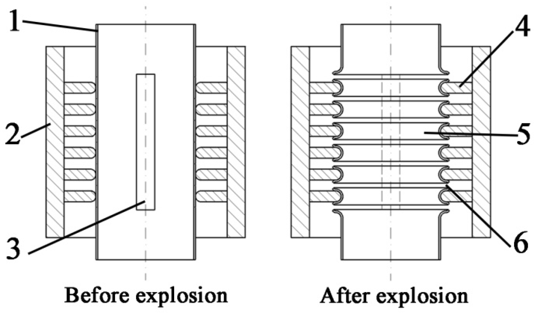
When the explosion happens inside the Barrel Conductor, a detonation wave which contains numerous explosive products and substantial pressure will propagate to the inner surface of the Barrel Conductor. Due the stress concentration, the Barrel Conductor will fracture on the grooves. The Support Epoxy will provide restrictions to the Barrel Conductor. As illustrated in Figure 2, a series of equidistant rings will be formed after the explosion. The arc will be ignited in the gaps between each of the two rings. After the multiple arcs are ignited, the current in the main circuit will be switched to the discharge resistors. The tremendous energy in the superconducting coil will be consumed before irreversible damage happens. The number and the dimension of the gaps are considered as the two main factors that affect the commutation ability.
A pyro-breaker prototype was designed with seven grooves and six support epoxies. The thermal performance and commutation ability of the prototype were tested under 40 kA. For further implementation in the QPS of CFETR, the commutation ability needs to be enhanced. More gaps guarantee the commutation ability of the breaker and the number of the grooves determines the numbers of the gaps generated by the explosion. However, an increase in the number of the grooves will also result in a higher resistance of conductors and a larger dosage of the explosives. Because the pyro-breaker is connected in a series with the superconducting coil, the thermal performance in the steady state is crucial to the designing of the breaker. A high resistance of the conductors will lead to a significant enlargement of the dimension. A larger structure will also cause the increase in the dosage, which is a potential hazard to the reliability and security of the entire QPS. Therefore, limiting the number of gaps is valuable in the designing process of the pyro-breaker.

2.2. Numerical Analysis of the Driving Mechanism

The detonation wave on the conductors and the dynamic response of the conductors after breaking is an extremely complex and transient dynamic problem. Moreover, the explosion takes place in a sealed chamber filled by water, which makes it difficult to observe. Hence, despite a large number of experiments, it is still impossible to obtain the details of the explosion process. In this case, the numerical simulation method shows great value in analyzing the diving mechanism of the pyro-breaker.
LS-DYNA is a non-linear, finite element structural analysis program, which has strong computing power for complex calculation models. Considering the highly non-linear problems in the explosion process, LS-DYNA has been applied for the simulation of the presented pyro-breaker [23,24].
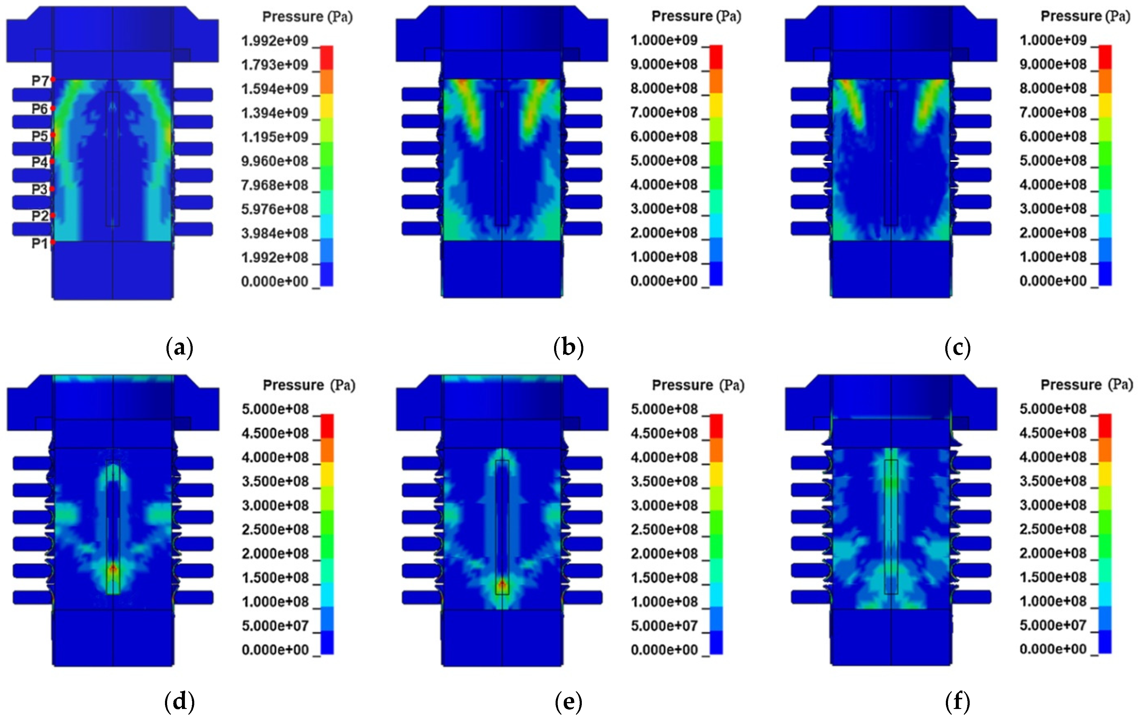
A simulation model of the CS was built with six epoxy rings and seven grooves in LS-DYNA. Figure 3 shows the simulated pressure distribution and breaking sequence of the Barrel Conductor at different time. The ignition takes place at the bottom of the explosive and transmits axially to the top. Once the explosive is detonated, the denotation wave begins to radially propagate to the Barrel Conductor. P1 to P7 are seven selected points on the grooves of the Barrel Conductor, as shown in Figure 3a. The distances between each selected point and the ignition point determines the time these points take to reach the peak pressure. The point with smaller distance has a shorter time to reach the peak pressure, while the breaking sequence is not only related to the time but also to the peak value and increasing rate of the pressure. As shown in Figure 3b, the detonation wave is superimposed in the center of the Barrel Conductor, which leads to the faster break on P3 and P4 at 35 μs. P5 breaks at 39 μs, as shown in Figure 3c. The detonation wave is rebounded and overlapped with the initial wave after the initial wave reaches the top of the barrel. The overlapped detonation wave breaks P2 and P6 at the 42 μs, as shown in Figure 3d. P7 breaks at 50 μs, as shown in Figure 3e. The peak pressure on P1 is the smallest among all the points, which is not big enough to break the groove. Only six gaps are generated after the explosion. Experiments show the same results as the simulation.

3. Application of Schavemaker Arc Model on Multiple Arcs

3.1. Schavemaker Arc Model

The Schavemaker black-box arc model has been utilized in an earlier study, in which the series of arcs are simplified as one arc. Through analysis of the pyro-breaker, the number of the gaps and the sequences of the gap formation can be regarded as the two main factors that affect the commutation ability. Thus, the number and forming sequence of the gaps in modeling will improve the accuracy of the arc model.
The Schavemaker equation defined by Equation (1) is a black-box arc model derived from the differential equation developed by Mayr [7].
1 g d g d t = 1 τ u i m a x E 0 i , P 0 + P 1 u i 1
  • g—the arc conductance
  • u—the arc voltage
  • i—the arc current
  • τ—the time constant
  • P0—the cooling power
  • E0—the reference arc voltage
Here, τ is the time constant with the unit of μs, which represents the increased speed of the arc resistance. P0 shows the cooling power of the breaker with the unit of kW, which depends on the designing and structure of the breaker, such as physical property and the pressure of the coolant. E0 is the reference arc voltage with the unit of kV. The cooling constant P1 is a constant used to regulate the cooling power P0 by the influence of the input power. The units of g, u and i are μΩ, kV and kA, respectively.
The parameter choices of the arc models are usually obtained by combining the theoretical analysis and experimental fitting. The values of τ and P0 can be fitted by the Parameter Sweep Strategy [25,26] from commutation test. E0 is dependent on the circuit parameters and irrelevant to the input power. Among all the parameters, P1 is the only one that depends on the inputting current. A method to study the P1 value rule was proposed and verified in the simplified simulation of the arc model [19]. The P1-I equation is defined by Equation (2). The unit of I is kA.
P 1 = 2 × 10 5 I + 0.9998

3.2. Parameter Fitting with the Experiment under 40 kA

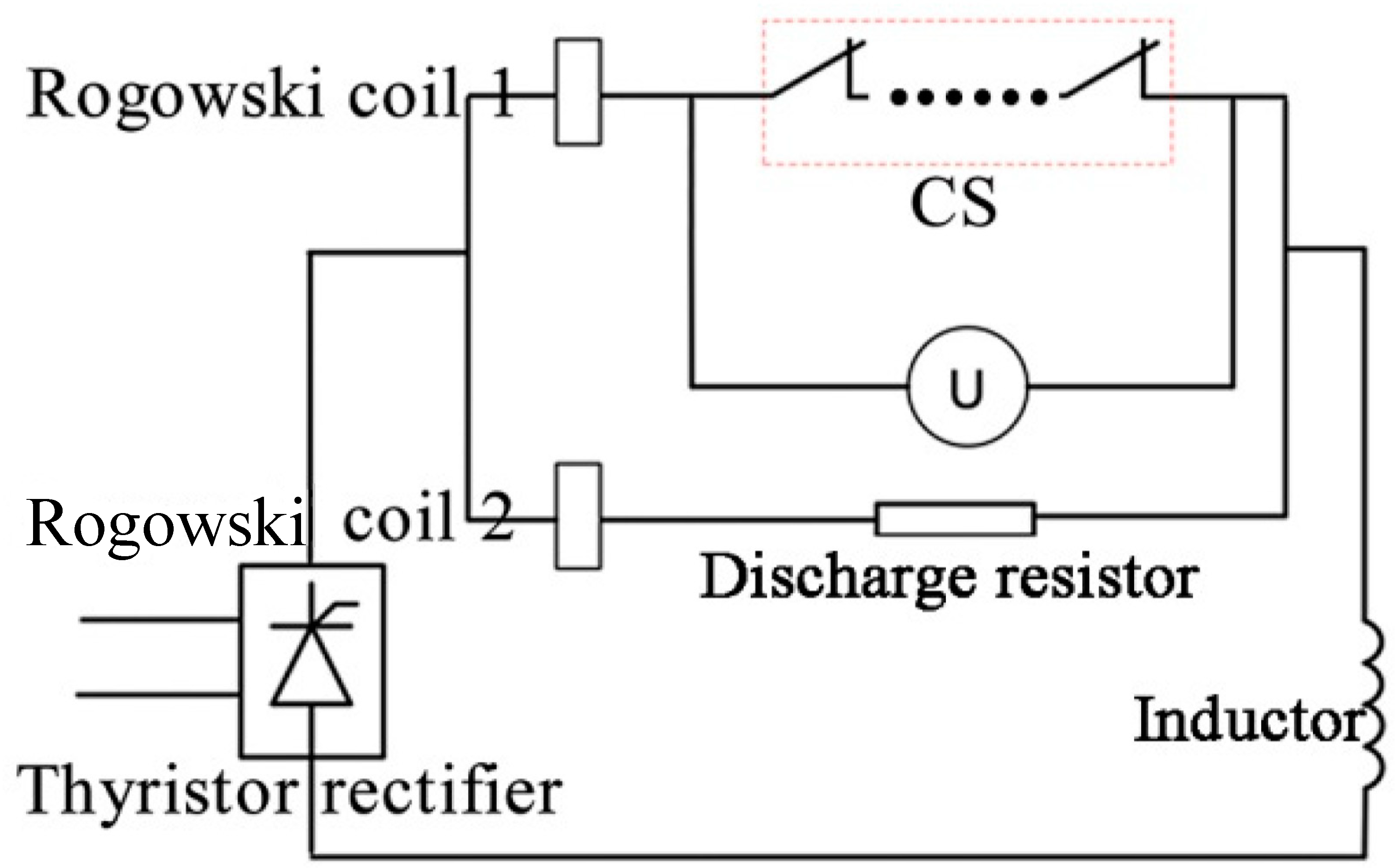
The experiment was carried out on a DC test platform under 40 kA. Figure 4 shows the circuit of the commutation test. An inductor with an inductance of 5 mH is connected in the main circuit to represent the superconducting coil. The inductor has a resistance of 2.5 mΩ. The discharge resistor is composed of a series of steel resistors with a resistance of 50 mΩ. The discharge resistor has an inductance of 20 μH.
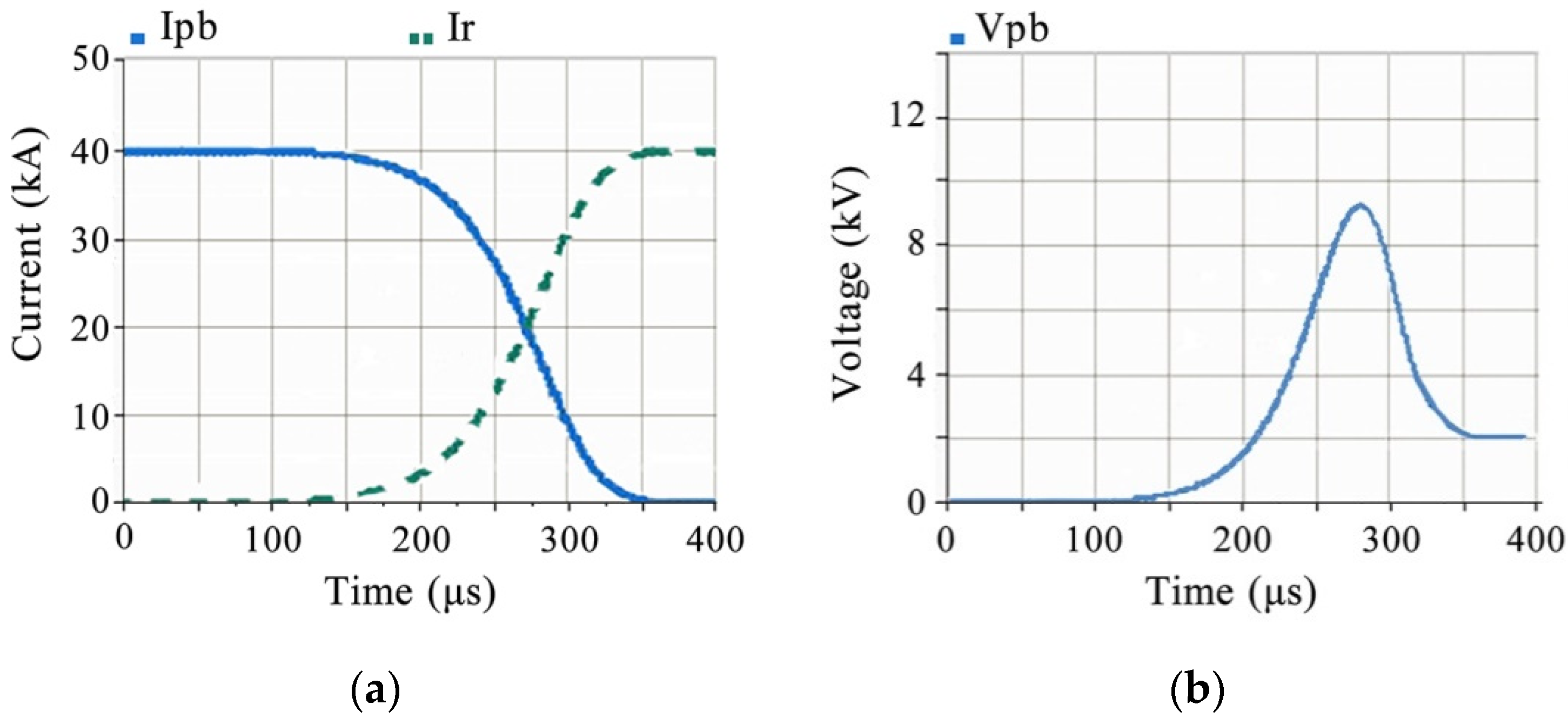
Figure 5 shows the results of the commutation test. Ipb and Ir are the current in the pyro-breaker branch and the discharge resistor branch, respectively. Vpb is the voltage across the pyro-breaker. Due to the delay caused by the detonating cord, the starting time of the commutation is set at 100 μs, which is a relative time for the convenience to record the time differences. The current commutation has the highest speed at 240 μs, which will lead to a large di/dt. A voltage spike of 9.17 kV will appear when di/dt reaches the largest value, approximately 0.46 kA/μs. The entire commutation completes at 321 μs.
A simulation circuit model of the commutation test was established in PSCAD to fit the arc model parameters, as shown in Figure 6. To be consistant with the characteristics of the electrical components in the test circuit, the inductance L1 in the main circuit is added with a resistor R1 and the discharge resistor R2 is added with an inductor L2. According to the test circuit: R1 = 2.5 mΩ, L1 = 5 mH, R2 = 50 mΩ and L2 =20 μH. The numerical analysis indicates that six gaps are generated in sequence after the explosion. So, six variable resistors are applied in the simulation to represent the arcs. The Schavemaker black-box arc model is applied to these variable resistors, Rarc1 to Rarc6. These variable resistors are triggered by timers. According to an idealized gap-generation sequence, Rarc1 and Rarc2 are set to be triggered at 100 μs, which is the same time with the starting commutation time in the commutation test; Rarc3 is triggered at 105 μs; Rarc4 and Rarc5 is triggered at 110 μs; Rarc6 is triggered at 115 μs. Ipb, and Ir are the currents flowing through the pyro-breaker and the discharge resistor. Vpb is the voltage across the series of the arc modules.
P0 = 2500 kW, τ = 0.025 μs. According to the circuit parameters, E0 is set to 2 kV. When the current of the DC source is 40 kA, P1 is 1.0006 calculated by Equation (2).
The simulation result is illustrated in Figure 7. The current Ipb starts to commutate immediately after the first arc module is triggered at 100 μs. The voltage across the breaker also starts to rise at the same time. The value of the voltage spike, which is 9.28 kV, appears at 243 μs. The commutation of the current Ipb finishes at 319 μs.
The commutation time is the time interval between the starting time and the finishing time of the entire commutation. The voltage spike time is the time interval between the starting time of the increase in the arc voltage and the occurring time of the voltage spike. As shown in Figure 5, the commutation time in the 40 kA test is 221 μs and the voltage spike time in the 40 kA test is 140 μs. As shown in Figure 7, the commutation time and the voltage spike time in the simulation with multi-arc modules are 219 μs and 143 μs, respectively. The simulation results are in accordance with the commutation experiment, indicating that the multiple-arc module simulation is feasible for use in analyzing the commutation process of the pyro-breaker with different numbers of gaps under a higher rated current.

4. Verification of the Arc Model under 60 kA

4.1. Simulation with the Mutiple-Arc Model

A commutation test has already been conducted on a prototype of the presented pyro-breaker with seven grooves under the current of 40 kA. However, the improvement of the current capability of the breaker to 40 kA~100 kA is a great challenge both in the thermal stability and commutation ability. A thermal study on the breaker shows that a single groove will approximately bring a resistance of 0.85 μΩ to the entire conductor system. Decreasing the number of the gaps generated in the explosion will enhance the thermal ability to a large extent. However, how the decreasing in the gaps affects the commutation has not been analyzed.
Three sets of simulation were conducted to compare the commutation process under the current of 60 kA with different number of arc modules. These arc modules are also triggered by timers, which has an initial time delay of 200 μs. The triggering sequence is set according to the numerical simulation of the explosion process. Since the general structure, the explosive dosage and the arc media remain the same, P0 = 2500 kW, τ = 0.025 μs. Moreover, according to the circuit parameters, E0 is set to 2 kV. When the current of the DC source is 60 kA, P1 is 1.001 calculated by Equation (2).
The same circuit shown in Figure 6 is used to run the simulation. To avoid an overvoltage caused by the commutation, L2 is set to 5 μH. The other electrical parameters remain the same. The simulation result is shown in Table 2. The current in the pyro-breaker starts to commutate immediately after the first arc module is triggered at 235 μs in each simulation.

4.2. Experiment

To verify the simulation, a pyro-breaker prototype with five grooves on the Barrel Conductor was manufactured to be tested under the current of 60 kA. The test circuit is shown in Figure 4. To be consistent with the simulation, the discharge resistor R was replaced by a low inductance resistor with the inductance of 5 μH and the resistance of 100 mΩ.
Figure 8 shows the results of commutation test. Due to the delay caused by the detonating cord, the starting time of the commutation is set at 100 μs, which is a relative time for the convenience to record the time differences. The current commutation has the highest speed at 284 μs, which will lead to a large di/dt. A voltage spike of 8.07 kV appears when di/dt reaches the largest value, at approximately 1.67 kA/μs. The entire commutation completes at 280 μs.

4.3. Discussion

The commutation time, the value and the occurring time of the voltage spike are three important factors in the commutation process, which determines whether the pyro-breaker meets the designing requirements of the QPS. The accuracy of the simulation mode can also be verified by comparing these three factors to the commutation test results.
It can be concluded from Table 2 that the decrease in the arc modules will result in an obvious extension of the commutation time and the voltage spike time. However, the values of the voltage spike only have an approximate 0.2% decrease with one less arc module.
As illustrated in Figure 8a, the commutation time for the pyro-breaker prototype under 60 kA with five grooves is 279 μs. As shown in Figure 8b, the voltage spike time is 184 μs. By examining the pyro-breaker after explosion, five grooves were all broken into gaps. This might have been because the detonation wave had a more even distribution with fewer grooves. The comparison between the simulation and the experiment is provided in Table 3.
It can be concluded from the comparison that the three commutation factors in the experiment are in accordance with the simulation with five arc modules. The voltage spike has the largest relative error among the three commutation factors. This might be dure to the gap forming sequence idealized from the numerical simulation. Moreover, the real sequence of the gap formation may also differ from the numerical simulation. However, the voltage spike simulated by the presented method is still regarded as consistent with the experiment results.

5. Conclusions

The commutation time, the value and the occurring time of the voltage spike are three important factors in the commutation process, which determines whether the pyro-breaker meets the designing requirements of the Quench Protection System (QPS). Several recent studies show that the QPS of the China Fusion Engineering Test Reactor (CFETR) will have the nominal current of 40 kA~100 kA. The existing pyro-breaker in China only has the nominal current of 15 kA, which leaves a significant gap for further development. More gaps guarantee the commutation ability of the breaker, but will also result in a higher resistance in conductors and a larger dosage of the explosives. On the one hand, the number of grooves determines the numbers of the gaps generated by the explosion. On the other hand, more grooves will bring higher resistance to the breaker, which will lead to a designing challenge for the cooling water system and the reliability of the entire structure. The pyro-breaker in ITER has the highest nominal current worldwide, which is 70 kA. However, no study has been proposed by the ITER project on the influence of the gap quantity on the commutation performance. This paper combines the numerical analyses of the driving mechanism of the pyro-breaker in LS-DYNA with the Schavemaker arc model to simulate the multi-arc commutation process. A pyro-breaker prototype was tested under the current of 60 kA. The test results are in accordance with the simulation and provide the theoretical basis for future development of the pyro-breaker in the QPS of CFETR. To limit the number of the gaps is valuable in the designing process of the pyro-breaker.
The dimensions of the gaps also have obvious effect on the commutation ability of the pyro-breaker. A small distance may lead to a long commutation time or even a failure of commutation. The dosage of explosive can ensure a sufficient dimension of the gaps, but may also cause damage to the entire breaker. Therefore, to optimize the dosage of explosive is also crucial to the design. Future work could be focused on establishing a reliable arc model, which can reflect the influence of the dimension of the gaps.

Author Contributions

Conceptualization, J.H. and J.L.; methodology, J.H.; validation, J.H., K.W. and J.L.; formal analysis, J.H.; writing—original draft preparation, J.H.; writing—review and editing, J.H., K.W. and J.L.; supervision, J.L. and K.W.; project administration, J.L.; funding acquisition, J.L. and K.W. All authors have read and agreed to the published version of the manuscript.

Funding

This research was funded by the National Key Research and Development Program of China, grant number 2017YFE0300504.

Acknowledgments

This work was supported by Shenzhen Clean Energy Research Institute. The authors would like to express gratitude to Honghao Ma of University of Science and Technology of China and the students who helped with the experiments.

Conflicts of Interest

The authors declare no conflict of interest.

References

  1. Ludin, G.A.; Amin, M.A.; Matayoshi, H.; Rangarajan, S.S.; Hemeida, A.M.; Takahashi, H.; Senjyu, T. Solid-State DC circuit breakers and their comparison in modular multilevel converter Based-HVDC transmission system. Electronics 2021, 10, 1204. [Google Scholar] [CrossRef]
  2. Bhatta, S.; Fu, R.; Zhang, Y. A New method of detecting and interrupting high impedance faults by specifying the Z-Source breaker in DC power networks. Electronics 2020, 9, 1654. [Google Scholar] [CrossRef]
  3. Niewind, J.; Hemdan, N.G.A.; Klosinski, C.; Bösche, D.; Kurrat, M.; Gerdinand, F.; Meisner, J.; Passon, S. Operation and protection of 380V DC distribution systems. In Proceedings of the 2017 IEEE Manchester PowerTech, Manchester, UK, 18–22 June 2017; pp. 1–6. [Google Scholar]
  4. Lee, K.A.; Cho, Y.M.; Lee, H.J. Circuit model and analysis of molded case circuit breaker interruption phenomenon. Electronics 2020, 9, 2047. [Google Scholar] [CrossRef]
  5. Pierri, R.; Moretta, R. An SVD approach for estimating the dimension of phaseless data on multiple arcs in fresnel zone. Electronics 2021, 10, 606. [Google Scholar] [CrossRef]
  6. Wang, D.; Liao, M.; Wang, R.; Li, T.; Qiu, J.; Li, J.; Duan, X.; Zou, J. Research on Vacuum arc commutation characteristics of a natural-commutate hybrid DC circuit breaker. Energies 2020, 13, 4823. [Google Scholar] [CrossRef]
  7. Mayr, O. Beitrage zur Theorie des Statischen und des Dynamischen Lichtbogens. Arch. Elektr. 1943, 37, 588–608. [Google Scholar] [CrossRef]
  8. Cassie, A.M. Arc rupture and circuit severity: A new theory. In Proceedings of the Conférence Internationale des Grands Réseaux Électriques à Haute Tension (CIGRE Report), Paris, France, 29 June–8 July 1939; Volume 102, pp. 1–14. [Google Scholar]
  9. Gammon, T.; Lee, W.; Zhang, Z.; Johnson, B.C. A review of commonly used DC arc models. IEEE Trans. Ind. Appl. 2015, 51, 1398. [Google Scholar] [CrossRef]
  10. Khakpour, A.; Franke, S.; Uhrlandt, D.; Gorchakov, S.; Methling, R. Electrical arc model based on physical parameters and power calculation. IEEE Trans. Plasma Sci. 2015, 43, 2721. [Google Scholar] [CrossRef]
  11. Rau, S.; Zhang, Z.; Lee, W. 3D magnetohydrodynamic modeling of DC arc in power system. IEEE Trans. Ind. Appl. 2016, 52, 4549–4555. [Google Scholar] [CrossRef]
  12. Fu, P.; Song, Z.Q.; Gao, G.; Tang, L.J.; Wu, Y.B.; Wang, L.S.; Liang, X.Y. Quench protection of the poloidal field superconducting coil system for the EAST tokamak. Nucl. Fusion. 2006, 46, S85. [Google Scholar] [CrossRef]
  13. Rummel, T.; Gaupp, O.; Lochner, G.; Sapper, J. Quench protection for the superconducting magnet system of WENDELSTEIN 7-X. IEEE Trans. Appl. Supercond. 2002, 12, 1382. [Google Scholar] [CrossRef]
  14. Barabaschi1, P.; Kamada, Y.; Shirai, H. Progress of the JT-60SA project. Nucl. Fusion. 2019, 59, 112005. [Google Scholar] [CrossRef]
  15. Song, I.; Choi, C.; Cho, M. Quench protection system for the superconducting coil of the KSTAR Tokamak. IEEE Trans. Appl. Supercond. 2007, 17, 1–6. [Google Scholar] [CrossRef]
  16. Manzuk, M.; Avanesov, S.; Roshal, A.; Bestuzhev, K.; Nesterenko, A.; Volkov, S. The 70 kA pyrobreaker for ITER magnet back-up protection. Fusion Eng. Des. 2013, 88, 1537–1540. [Google Scholar] [CrossRef]
  17. Zhu, J.; Zhang, Y.; Dong, Y.; HL-2A Team. Characterization of plasma current quench during disruptions at HL-2A. Plasma Sci. Technol. 2017, 19, 055101. [Google Scholar] [CrossRef] [Green Version]
  18. Ren, Y.; Zhu, J.; Gao, X.; Shen, F.; Chen, S. Electromagnetic, mechanical and thermal performance analysis of the CFETR magnet system. Nucl. Fusion. 2015, 55, 093002. [Google Scholar] [CrossRef]
  19. Zheng, J.; Song, Y.; Liu, X.; Lu, K.; Qin, J. Overview of the Design Status of the Superconducting Magnet System of the CFETR. IEEE Trans. Appl. Supercond. 2018, 28, 4204305. [Google Scholar] [CrossRef]
  20. Song, Y.; Wu, S.; Li, J.; Wan, B.; Wan, Y.; Fu, P.; Ye, M.; Liu, S.; Gao, X. Concept design of CFETR Tokamak machine. IEEE Trans. Plasma Sci. 2013, 42, 503–509. [Google Scholar] [CrossRef]
  21. Schavemaker, P.H.; Slui, L. An improved Mayr-type arc model based on current-zero measurements [circuit breakers]. IEEE Trans. Power Deliv. 2000, 15, 580–584. [Google Scholar] [CrossRef]
  22. He, J.; Wang, K.; Li, J. Application of an Improved mayr-type arc model in pyro-breakers utilized in superconducting fusion facilities. Energies 2021, 14, 4383. [Google Scholar] [CrossRef]
  23. Tang, C.; Song, Z.; Li, C.; Wang, Z.; Ye, J.; Li, H.; Fu, P. Computational investigation on the explosively actuated switch utilized in quenching protection system. Fusion Eng. Des. 2021, 163, 112157. [Google Scholar] [CrossRef]
  24. He, J.; Wang, K.; Fu, P.; Song, Z.; Tang, C.; Ye, J. Numerical Analysis of a Pyro-breaker Utilized in Superconducting Fusion Facility. In Proceedings of the 2021 IEEE 4th International Electrical and Energy Conference (CIEEC), Wuhan, China, 28–30 May 2021; pp. 1–6. [Google Scholar] [CrossRef]
  25. Lim, S.; Khan, U.A.; Lee, J.; Lee, B.; Kim, K.; Gu, C. Simulation analysis of DC arc in circuit breaker applying with conventional black box arc model. In Proceedings of the 2015 3rd International Conference on Electric Power Equipment–Switching Technology (ICEPE-ST), Busan, Korea, 25–28 October 2015; pp. 332–336. [Google Scholar] [CrossRef]
  26. Park, K.; Lee, H.; Asif, M.; Lee, B.; Shin, T.; Gu, C. Assessment of various kinds of AC black-box arc models for DC circuit breaker. In Proceedings of the 2017 4th International Conference on Electric Power Equipment-Switching Technology (ICEPE-ST), Xi’an, China, 22–25 October 2017; pp. 465–469. [Google Scholar]
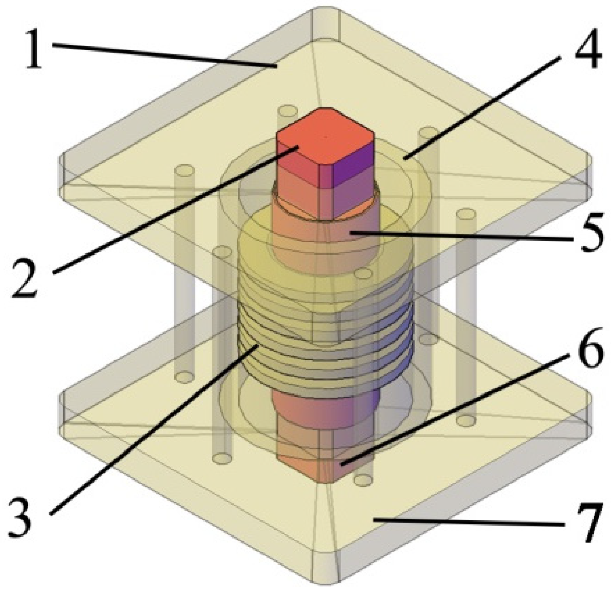
Figure 1. Structure of the CS: 1 Upper Epoxy Plate, 2 Upper Conductor, 3 Support Epoxy, 4 Epoxy Barrel, 5 Barrel Conductor, 6 Lower Conductor, 7 Lower Epoxy Plate.
Electronics 11 01702 g001
Figure 2. Formation of the Barrel Conductor in operation: 1 Barrel Conductor, 2 Epoxy Barrel, 3 Explosive, 4 Support Epoxy, 5 Rings, 6 gaps.
Electronics 11 01702 g002
Figure 3. Pressure contour and breaking sequence of the Barrel Conductor at: (a) 26 μs (b) 35 μs; (c) 39 μs; (d) 42 μs; (e) 50 μs and (f) 70 μs.
Electronics 11 01702 g003
Figure 4. The circuit of the commutation test.
Electronics 11 01702 g004
Figure 5. Commutation test at 40 kA: (a) Current oscillogram, (b) Voltage oscillogram.
Electronics 11 01702 g005
Figure 6. The circuit model of the commutation test in PSCAD.
Electronics 11 01702 g006
Figure 7. Simulation results of the pyro-breaker at 40 kA: (a) Current oscillogram; (b) Voltage oscillogram.
Electronics 11 01702 g007
Figure 8. Pyro-breaker tested at 60 kA: (a) Current oscillogram; (b) Voltage oscillogram.
Electronics 11 01702 g008
Table 1. The main parameters of the pyro-breakers in different QPSs.
FacilitiesNominal VoltageNominal CurrentCommutation Time
EAST3 kV15 kA<100 μs
W7-78 kV20 kA301 μs
JT60-SA5 kV25.7 kA350 μs
KSTAR8 kV40 kA200 μs
ITER10 kV70 kA350 μs
Table 2. The simulation results of the different numbers of arc modules.
Number of Arc ModulesCommutation TimeVoltage SpikeVoltage Spike Time
6264 μs8.15 kV175 μs
5276 μs8.13 kV180 μs
4290 μs8.11 kV187 μs
Table 3. The comparison between the simulation and the experiment under 60 kA.
Commutation FactorsSimulation ResultExperiment ResultsRelative Error
Commutation time276 μs279 μs1.1%
Voltage spike8.13 kV8.07 kV7%
Voltage spike time180 μs184 μs2.2%
Publisher’s Note: MDPI stays neutral with regard to jurisdictional claims in published maps and institutional affiliations.