
Continuously Adjustable Micro Valve Based on a Piezoelectric Actuator for High-Precision Flow Rate Control


Abstract
:1. Introduction
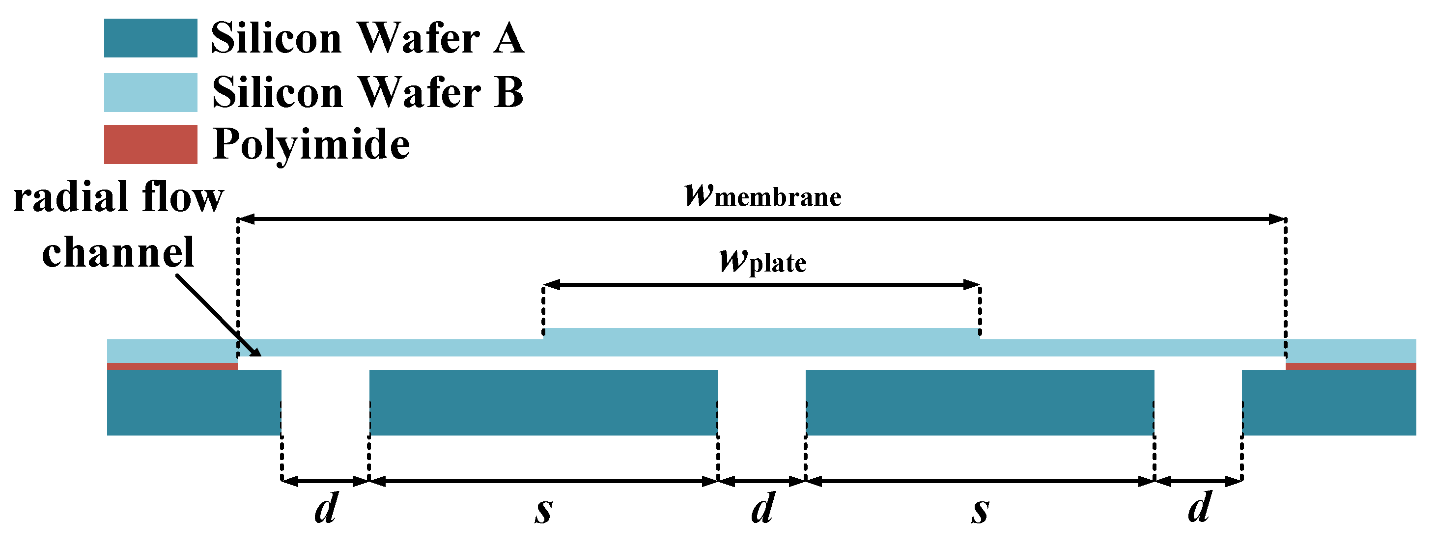
2. Structure Design
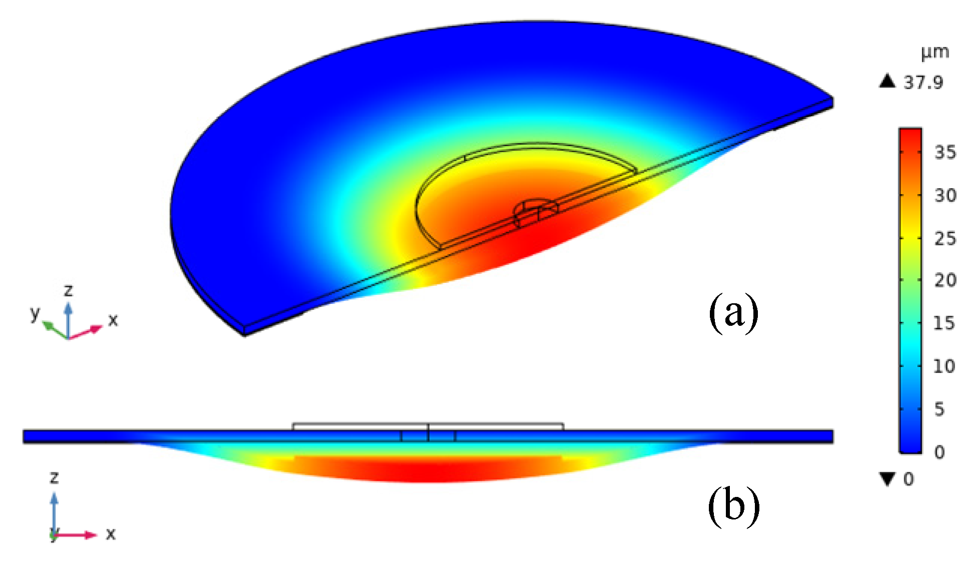
3. Simulation
4. Fabrication Results
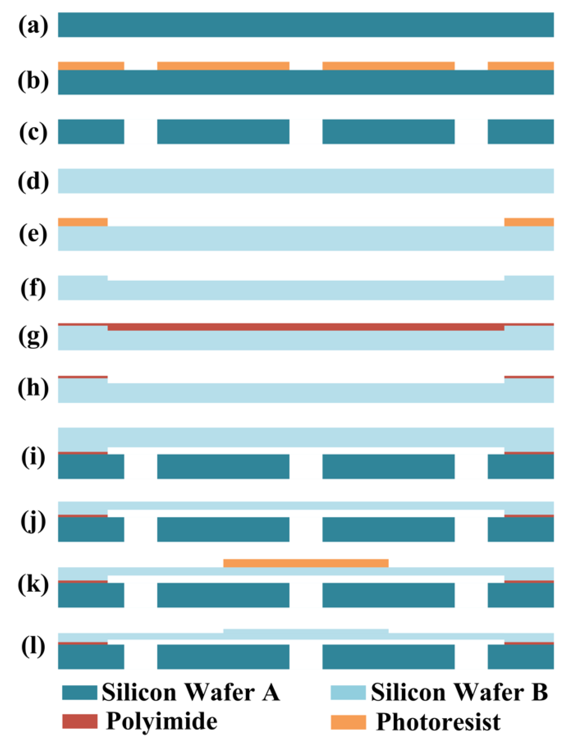
4.1. Fabrication Process
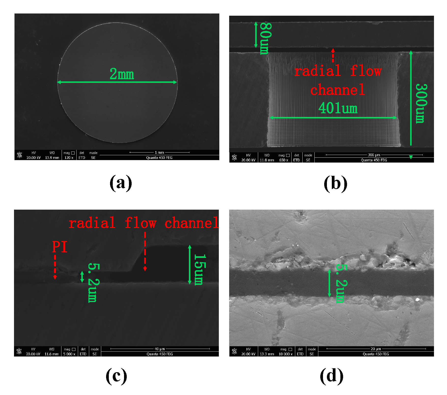
4.2. Fabrication Results
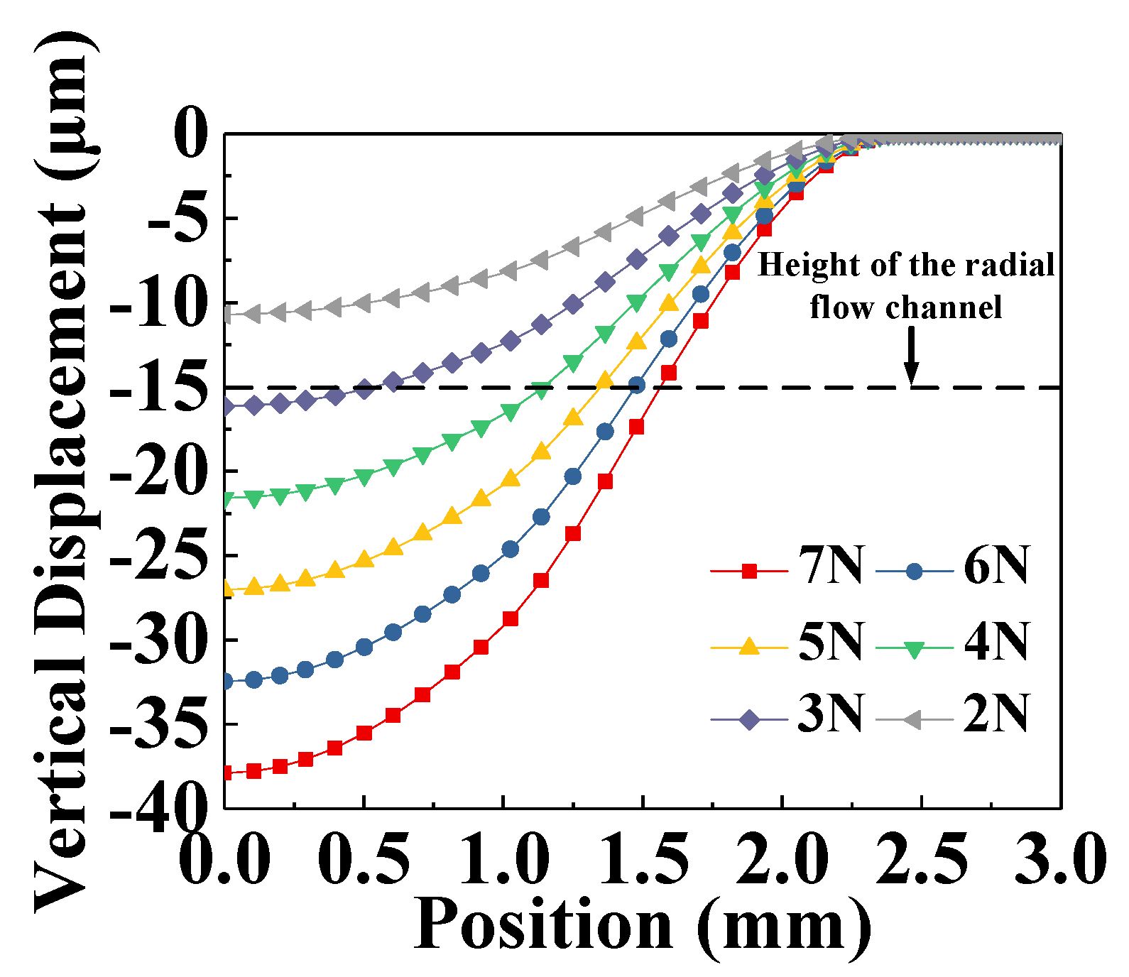
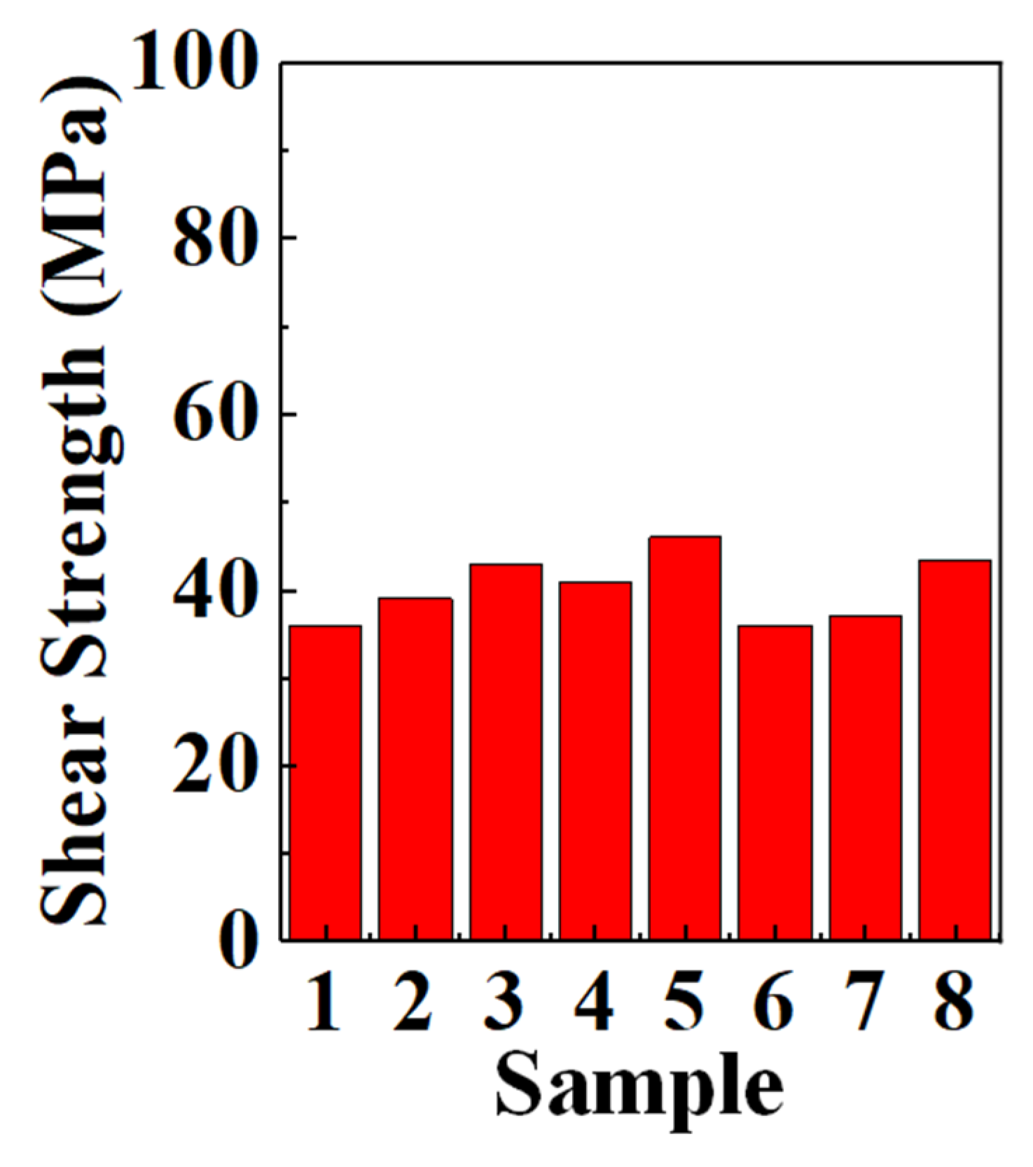
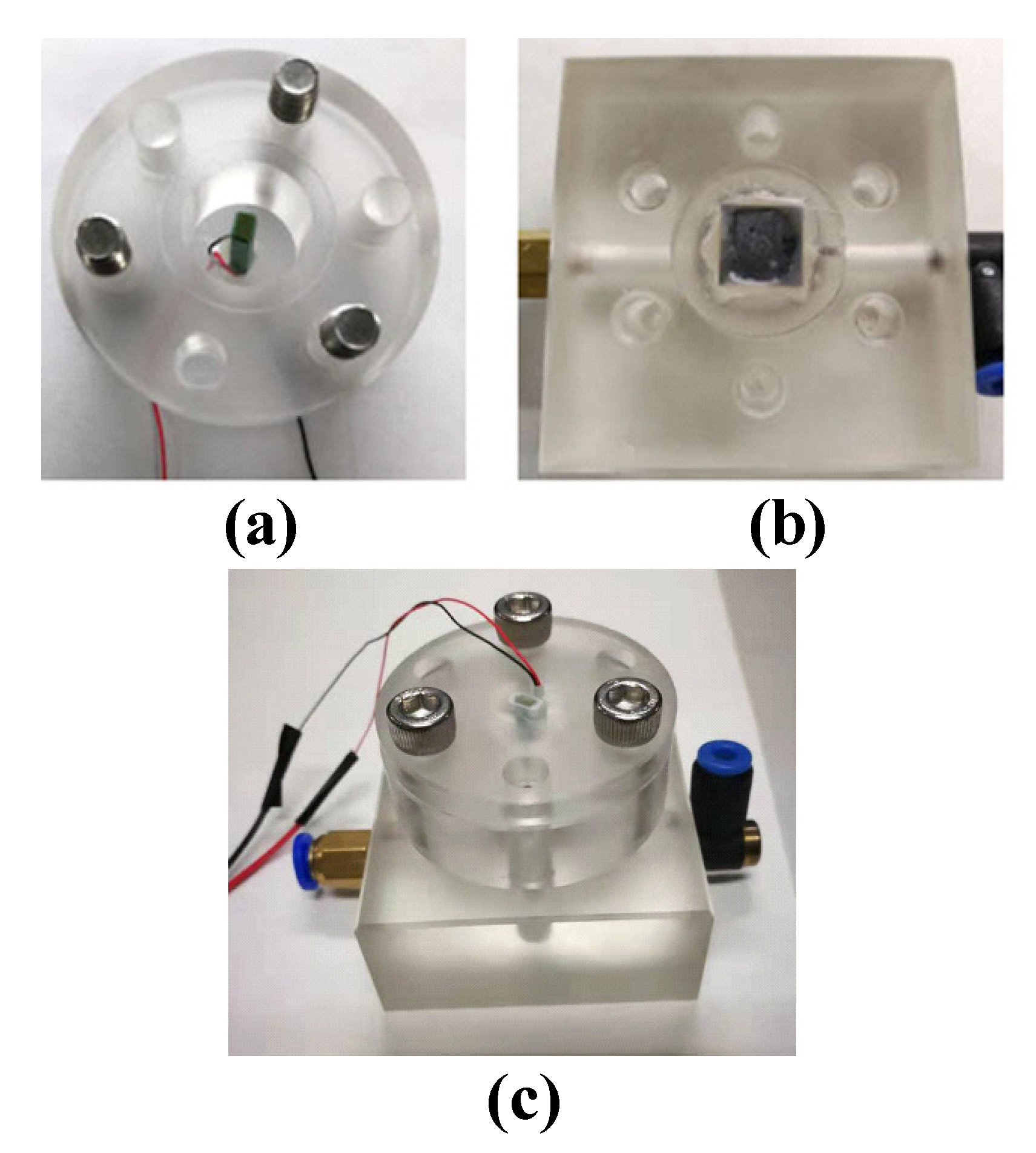
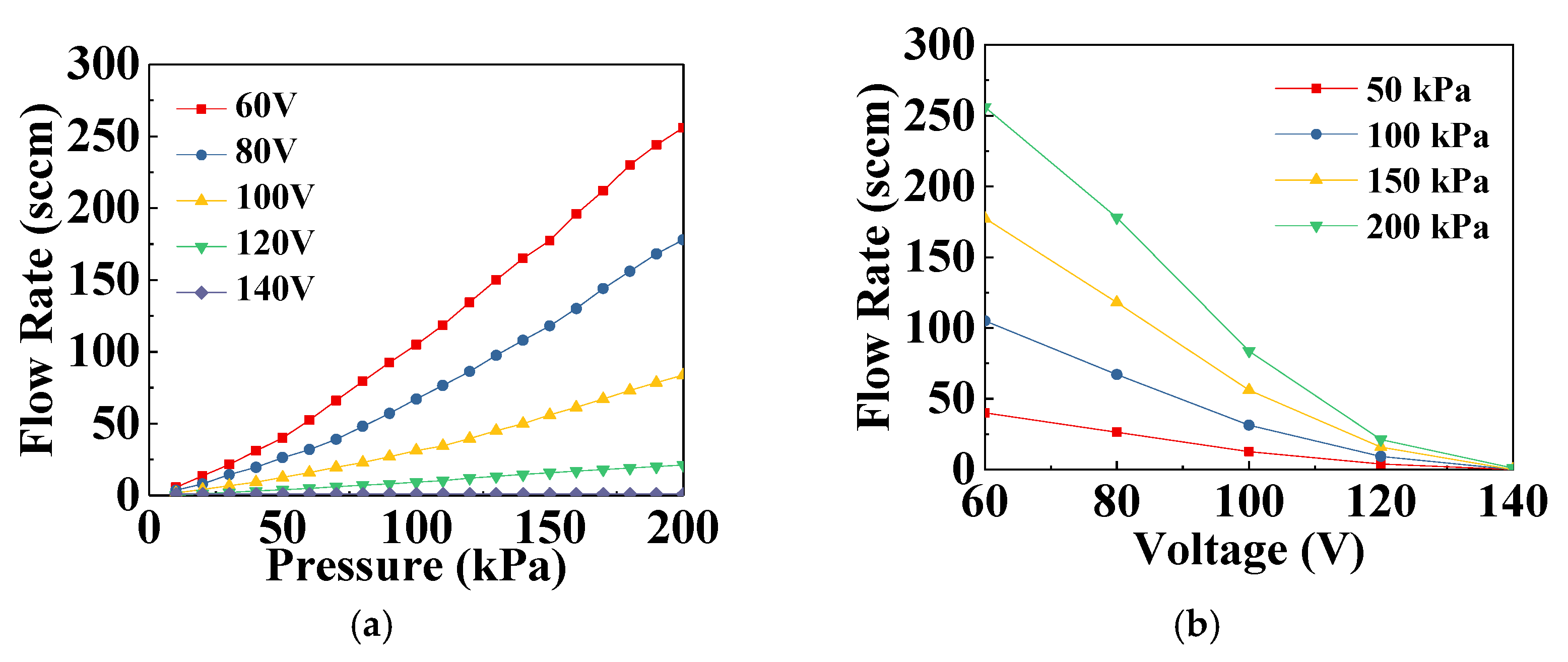
5. Experimental Results
6. Conclusions
Author Contributions
Funding
Conflicts of Interest
References
- Evans, A.T.; Park, J.M.; Chiravuri, S.; Gianchandani, Y.B. A low power, microvalve regulated architecture for drug delivery systems. Biomed. Microdevices 2010, 12, 159–168. [Google Scholar] [CrossRef] [PubMed]
- Li, T.; Evans, A.T.; Chiravuri, S.; Gianchandani, R.Y.; Gianchandani, Y.B. Compact, power-efficient architectures using microvalves and microsensors, for intrathecal, insulin, and other drug delivery systems. Adv. Drug Deliver. Rev. 2012, 64, 1639–1649. [Google Scholar] [CrossRef] [PubMed]
- Chen, S.; Lu, S.; Liu, Y.; Wang, J.T.; Tian, X.C.; Liu, G.J.; Yang, Z.G. A normally-closed piezoelectric micro-valve with flexible stopper. AIP Adv. 2016, 6, 045112. [Google Scholar] [CrossRef] [Green Version]
- Oh, K.W.; Rong, R.; Ahn, C.H. Miniaturization of pinch-type valves and pumps for practical micro total analysis system integration. J. Micromech. Microeng. 2005, 15, 2449–2455. [Google Scholar] [CrossRef]
- Im, S.B.; Unnin, M.J.; Jin, G.J.; Shim, J.S. A disposable on-chip micro valve and pump for programmable microfluidics. Lab Chip 2018, 18, 1310–1319. [Google Scholar] [CrossRef] [PubMed]
- Kovarik, M.L.; Gach, P.C.; Ornoff, D.M.; Wang, Y.; Balowski, J.; Farrag, L.; Allbritton, N.L. Micro Total Analysis Systems for Cell Biology and Biochemical Assays. Anal. Chem. 2012, 84, 516–540. [Google Scholar] [CrossRef] [PubMed] [Green Version]
- He, X.W.; Chen, Q.S.; Zhang, Y.D.; Lin, J.M. Recent advances in microchip-mass spectrometry for biological analysis. TrAC-Trend. Anal. Chem. 2014, 53, 84–97. [Google Scholar] [CrossRef]
- Waibel, G.; Kohnle, J.; Cernosa, R.; Storz, M.; Schmitt, M.; Ernst, H.; Sandmaier, H.; Zengerle, R.; Strobelt, T. Highly integrated autonomous microdosage system. Sens. Actuators A 2003, 103, 225–230. [Google Scholar] [CrossRef]
- Groen, M.S.; Brouwer, D.M.; Wiegerink, R.J.; Lötters, J.C. Design Considerations for a Micromachined Proportional Control Valve. Micromachines 2012, 3, 396–412. [Google Scholar] [CrossRef] [Green Version]
- Mqa, R.; Song, C.P.; Rashida, A.; Xin, L.K.; Ling, L.P. Electromagnetic Actuation Dual-Chamber Bidirectional Flow Micropump. Sens. Actuator A Phys. 2018, 282, 17–27. [Google Scholar] [CrossRef]
- Chang, M.P.; Maharbiz, M.M. Electrostatically-driven elastomer components for user-reconfigurable high density microfluidics. Lab Chip 2009, 9, 1274. [Google Scholar] [CrossRef] [PubMed]
- Leistner, H.; Anheuer, D.; Bosetti, G.; Schrag, G.; Richter, M. Modeling and Manufacturing of an Electrostatically Driven Actuator for Micropumps. In Proceedings of the 2021 MikroSystemTechnik Congress, Stuttgart-Ludwigsburg, Germany, 8–10 November 2021. [Google Scholar]
- Atik, A.C.; Zkan, M.D.; Zgür, Z.; Kulah, H.; Yildirim, E. Modeling and Fabrication of Electrostatically Actuated Diaphragms for On-chip Valving of MEMS-Compatible Microfluidic Systems. J. Micromech. Microeng. 2020, 30, 115001. [Google Scholar] [CrossRef]
- Oh, K.W.; Ahn, C.H. A review of microvalves. J. Micromech. Microeng. 2006, 16, 13–39. [Google Scholar] [CrossRef]
- Rogge, T.; Rummler, Z.; Schomburg, W.K. Polymer micro valve with a hydraulic piezo-drive fabricated by the AMANDA process. Sens. Actuators A 2004, 110, 206–212. [Google Scholar] [CrossRef]
- Shao, P.; Rummler, Z.; Schomburg, W.K. Polymer micro piezo valve with a small dead volume. J. Micromech. Microeng. 2004, 14, 305–309. [Google Scholar] [CrossRef]
- Yang, E.H.; Lee, C.; Mueller, J.; George, T. Leak-Tight Piezoelectric Microvalve for High-Pressure Gas Micropropulsion. J. Microelectromech. Syst. 2004, 13, 799–807. [Google Scholar] [CrossRef]
- Itabashi, T.; Zussman, M.P. High Temperature Resistant Bonding Solutions Enabling Thin Wafer Processing (Characterization of Polyimide Base Temporary Bonding Adhesive for Thinned Wafer Handling). In Proceedings of the 2010 Proceedings 60th Electronic Components and Technology Conference, Las Vegas, NV, USA, 1–4 June 2010. [Google Scholar]
- Itabashi, T.; Kotani, M.; Zussman, M.P.; Zoschke, K.; Fischer, T.; Töpper, M.; Ishida, H. High temperature Bonding Solutions Enabling Thin Wafer Process and Handling on 3D-IC Manufacturing. In Proceedings of the 2011 IEEE International 3D Systems Integration Conference, Osaka, Japan, 1–4 January 2011. [Google Scholar]

| Parameter | Variable | Value (μm) |
|---|---|---|
| Inlet/outlet diameter | d | 400 |
| Inlet/outlet height | h | 300 |
| Inlet/outlet spacing | s | 1600 |
| Membrane diameter | wmembrane | 4800 |
| Plate diameter | wplate | 2000 |
| Membrane thickness | tmembrane | 80 |
| Plate thickness | tplate | 50 |
| Channel diameter | dchannel | 4800 |
| Channel height | hchannel | 15 |
Publisher’s Note: MDPI stays neutral with regard to jurisdictional claims in published maps and institutional affiliations. |
© 2022 by the authors. Licensee MDPI, Basel, Switzerland. This article is an open access article distributed under the terms and conditions of the Creative Commons Attribution (CC BY) license (https://creativecommons.org/licenses/by/4.0/).
Share and Cite
Ding, Y.; Cai, Y.; Li, Y. Continuously Adjustable Micro Valve Based on a Piezoelectric Actuator for High-Precision Flow Rate Control. Electronics 2022, 11, 1689. https://doi.org/10.3390/electronics11111689
Ding Y, Cai Y, Li Y. Continuously Adjustable Micro Valve Based on a Piezoelectric Actuator for High-Precision Flow Rate Control. Electronics. 2022; 11(11):1689. https://doi.org/10.3390/electronics11111689
Chicago/Turabian StyleDing, Yingli, Yongzhi Cai, and Yanmei Li. 2022. "Continuously Adjustable Micro Valve Based on a Piezoelectric Actuator for High-Precision Flow Rate Control" Electronics 11, no. 11: 1689. https://doi.org/10.3390/electronics11111689
APA StyleDing, Y., Cai, Y., & Li, Y. (2022). Continuously Adjustable Micro Valve Based on a Piezoelectric Actuator for High-Precision Flow Rate Control. Electronics, 11(11), 1689. https://doi.org/10.3390/electronics11111689