Article

An Ultra-Wideband Linear-to-Circular Polarization Converter Based on a Circular, Pie-Shaped Reflective Metasurface

1
School of Electronic Engineering, Beijing University of Posts and Telecommunications, Beijing 100876, China
2
Department of Electronics, Quaid-e-Azam University, Islamabad 15320, Pakistan
3
State Key Laboratory of Networking and Switching Technology, Beijing University of Posts and Telecommunications, Beijing 100876, China
*
Author to whom correspondence should be addressed.
Electronics 2022, 11(11), 1681; https://doi.org/10.3390/electronics11111681
Submission received: 30 April 2022 / Revised: 18 May 2022 / Accepted: 23 May 2022 / Published: 25 May 2022
(This article belongs to the Section Power Electronics)

Abstract

:
In this paper, we present an ultrawideband reflective metasurface with the properties of an LTC-PC, which is an orthotropic composition with two mutually orthogonal symmetric axes, v and u, and 45° rotation about the vertical y-axis. Based on the metasurface unit cell, it seems like a circular pie embedded with a rectangular patch. The converter can convert LP electromagnetic (EM) waves to CP waves over the bands from 20.18 GHz to 33.93 GHz, with a 3-dB AR bandwidth of up to 50.8% and a circular polarization wave that is RHCP (right hand CP). Moreover, the linear-to-circular PCR exceeds 98% in the frequency bands of 20–34 GHz. A comprehensive theoretical investigation was conducted to determine the fundamental cause of the LTC polarization conversion. The φ u v between two reflection coefficients at v- and u-polarized incidences is ±90°, which fully anticipates the axial ratio of the reflected wave. Any reflective metasurface can be used as an efficient LTC-PC if the φ u v is close to ±90°.

1. Introduction

The polarization state is one of the most distinctive features of EM waves. A polarization converter consists of a commonly used technology that allows it to be freely adjusted. Recently, natural materials have been widely used to manipulate polarization, optical activity, and birefringence, especially in applications such as circular polarizers or quarter-wave plates [1,2]. Nowadays, small antennas are increasingly used in wireless communication networks [3]. To alleviate the problem of the wide frequency band, magnetic materials and artificial dielectrics such as metamaterials (MTMs) have been proposed [4]. Antennas, polarizers, and filters are all made from dielectric materials and ground planes. By acting as power absorbers for electromagnetic waves (EMWs), MTMs are used to reduce unwanted frequencies (similar to FSS) that can cause unwanted EMW coupling in radar applications [5]. The FSS was proposed as an ultra-wideband reflector and has been used to solve several critical problems in a variety of research areas [6]. In addition, the FSS is constantly evolving to meet the growing demand for an extended BW, not only for telecommunications but also for many modern applications that rely on a specific BW to function. As a result, breakthrough technologies that can efficiently generate diverse signals over a wide range of frequencies are being sought worldwide. Many techniques, including multilayer and single-layer designs, have been proposed to improve the gain of ultrawideband planar antennas using FSS [7]. The idea of using the FSS single layer as a reflector is identical to that of a partially reflective surface (PRS) that passes some frequencies while acting as a passband filter and reflects others when acting as a stopband filter. A distributed EM filter, such as an FSS, produces a frequency response that can be controlled and matched to the frequency allocation of the wireless system [8]. It can operate as a passband or stopband filter for radio waves propagating over the surface. There are two types of polarizers: reflective and transmissive. On the other hand, traditional polarization control techniques are limited by their bulky dimensions. Therefore, miniaturized devices are essential in reality. Since most polarizers suffer from the general drawback of low bandwidth, bandwidth expansion remains one of the most important research topics, which has led to numerous studies [9,10,11,12,13]. In the last decade, it has been discovered that metasurfaces offer a practical approach to manipulating the polarization of electromagnetic waves, which has led to much interest. Most research has focused on a single function, suggesting that the structure can regulate and change only one form of polarization in a single band: LTC or CPC and cross conversion. Recently, a single multifunctional design has been used to convert linear and circular polarizations. A reflectively polarized rotating metasurface consisting of microstrip lines and two meander lines is presented to achieve LTC conversions at lower and higher frequencies at incident angles [14]. In previous works, many proposals have been made for using metasurfaces to fabricate transmission-type [15,16,17,18,19,20,21] and reflection-type [22,23,24,25,26] LTC polarization converters. One of the various types of multi-order plasmon resonators that have been studied is the polarization rotator, which converts an LP wave to its orthogonal counterpart after reflection [27,28,29,30,31].
Anisotropic impedance-based metasurfaces have been used to convert LP to CP waves [32,33,34,35]. For example, in [32], a double V-shaped ring resonator was implemented to obtain LTC-PC in the THz range with an 80% FBW. In [34], a multilayer topology was developed to increase the operating bandwidth in the frequency band from 4.7 to 21.7 GHz with the incident wave. In comparison, the multi-polarization converter has been little explored despite its usefulness for a variety of applications. According to Jiang et al. [36], the polarization modes of waves can be flexibly controlled by changing physical parameters. The conversion of LP incident to CP reflected waves by varying physical parameters using a meta-based broadband reflector has been reported [37]. A multiband polarization converter with a paired-L-shaped design was presented in [38]. On the other hand, the cross-polarization converter (CPC) bands are somewhat narrow. A multi-polarization converter was presented in [39,40,41]. However, due to the coupling effect between the cut-wire and meander-lines, the design of a such structure in other frequency ranges is challenging.
In this study, we investigate and design an ultrawideband LTC-PC, which depends on a metasurface that can convert LP (linearly polarized)-EM waves into CP (circularly polarized) waves in a relative bandwidth (from 20.18 GHz to 33.93 GHz). The proposed metasurface can convert a y-incident polarized wave into an RHCP wave. Numerical simulations are used to study the performance and gain physical insights. Parametric analysis will be performed to determine a design parameter for different frequency ranges. To validate the polarization converter, we use simulations and calculations and provide a complete theoretical study of the ultra-wideband LTC-PC with good efficiency.

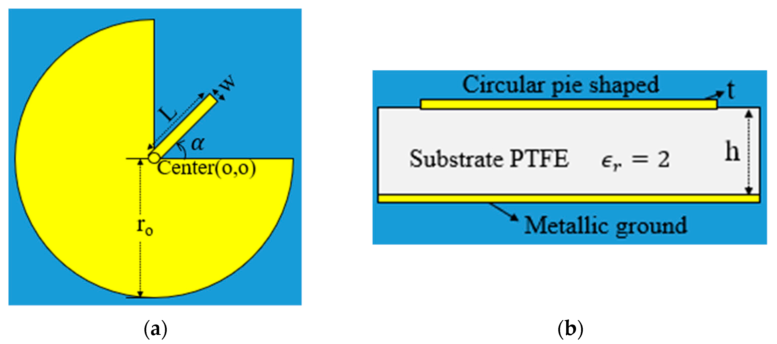
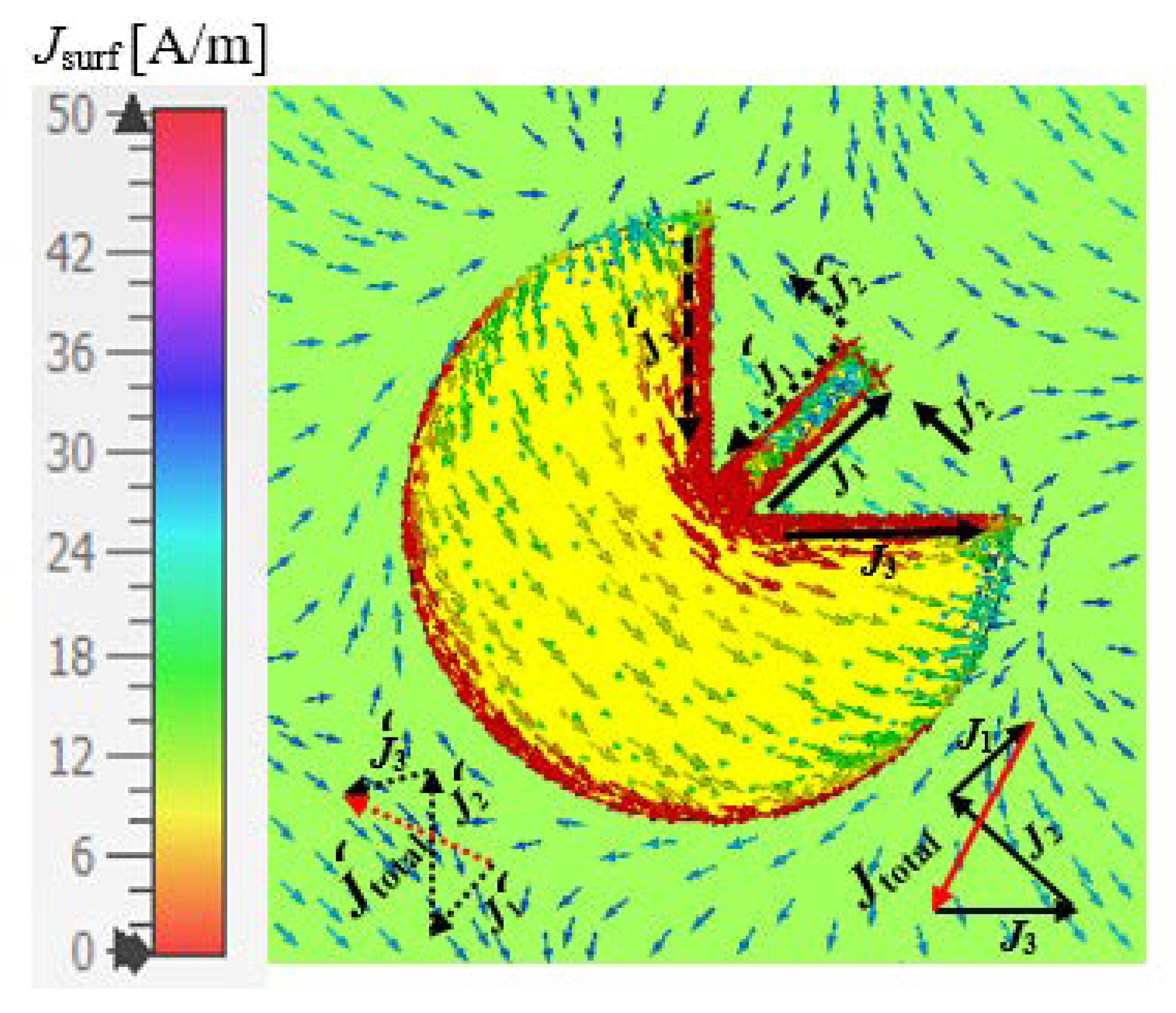
2. Metasurface Design and Method

Figure 1 shows the metasurface structure of the LTC polarization conversion. The basic unit of the converter consists of a circular pie shape grounded with a copper sheet. The circular pie shape is isolated from the substrate by a dielectric PTFE height (h = 1.6 mm) with ϵ r = 2 and a tangent loss of tan δ = 0.0018 . The bottom copper ground plane is fully reflective. The copper patch is (t = 0.017 mm and σ (electrical conductivity) = 5.8 × 10 7 S/m) thick at the bottom and top layers. Figure 1 lists the other parameters of the unit cell: i.e., r0 = 2.0 mm, W = 0.28 mm, L = 1.5 mm and α (rectangular patch rotation angle) = 45°.
The small rectangular patch is inserted at the origin of a circular, pie-shaped design, as shown in Figure 1. A series of simulations were performed using CST MWS to evaluate the LTC polarization conversion efficiency of the design. The x- and y-axes were constrained by unit cell boundary conditions, while the z-axis was excited by a Floquet port. When a plane wave with a y- or x-polarization impinges on the top surface of the proposed design (i.e., E y i = E y i e y or E x i = E x i e x ), the reflected wave of the y-incident wave can be equated as E r = E x r e x + E y r e y = r x y exp ( j φ x y ) E y i e x + r y y exp ( j φ y y ) E y i e y , where r y y = | E y r / E y i | and r x y = | E x r / E y i | are the reflection ratios of y-to-y (co-polarization) and y-to-x (cross-polarization), while φ y y and φ x y represent the subsequent phases. The y- and x-axes have unit vectors ( e y , e x ). The letters “r” and “i” represent reflected and incident waves, respectively. The incident wave can be converted from linear to circular under certain conditions, for example when r y y = r x y and φ y x = φ y y φ x y = ± 90 ° = 2 k π ± π / 2 , where (k = 0, 1, 2…). Figure 2 shows the magnitudes of the simulated r y y and r x y reflection coefficients of a circular pie shape. The magnitudes of r y y and r x y of a circular pie shape are the same in the frequency band of 20–33 GHz, as shown in Figure 2a. Moreover, Figure 2b shows that the phase differences in the frequency band 18–36 GHz are often equal to −90°, which is consistent with the relationship ( φ y x = φ y y φ x y = ± 90 ° = 2 k π ± π / 2 ,   k = 0 ,   1 ,   2 ). According to the previous simulation, this behavior is reversed by the illumination of the y-incident wave, which is much closer to an RHCP wave over 20.18–33.93 GHz. Another parameter, called the axial ratio (AR), is introduced to analyze the LTC polarization conversion with a promising technique. We determined the AR of the reflected wave using the simulation data in Figure 2. The axial ratio is given as: AR = ( ( r x y 2 + r y y 2 + a ) / ( r x y 2 + r y y 2 a ) ) 1 2 , where a = r x y 4 + r y y 4 + 2 r x y 2 r y y 2 cos ( 2 φ y x ) . The calculated axial ratio of a circular pie shape as a function of frequency is much lower than 3 dB in the ultrawideband (20.18–33.93 GHz), as shown in Figure 3a. This ultra-wideband with a relative bandwidth of 50.8% (FBW (%) =   ( ( f h f l ) / f 0 ) × 100 ) is used for the designed LTC polarization conversion. Moreover, the axial ratio is kept below 2 dB, indicating that the PCR of the polarization converter is more than 95%. The reflection coefficients of LTC-PC, PCR and PER are calculated using the above-simulated results, where, r L H C P y = 1 2 ( r x y i r y y ) , r R H C P y = 1 2 ( r x y + i r y y ) , PCR = | r R H C P y | 2 / ( | r R H C P y | 2 + | r L H C P y | 2 ) and PER = 20 log ( r x y / r y y ) . PCR is used to evaluate the effectiveness of cross-polarization conversion. Figure 3b shows the magnitudes of a circular pie shape of proposed r L H C P y and r R H C P y . The r R H C P y magnitude in the 3-dB band is considered to be very close to 0 dB, which means that the reflected wave at the y-polarized incidence has been almost completely converted to an RHCP wave. In addition, polarization conversion and extinction ratio (PCR and PER) are two other important factors to consider when evaluating conversion efficiency. The polarization extinction ratio (PER) between the r R H C P y and r L H C P y wave determines the circular polarization efficiency. The PER should be more than +20 dB (RHCP) or −20 dB (LHCP) to ensure the same magnitude and 90° ( φ y x ) following in a CP (circular polarized) wave. The PCR of a circular pie shape is above (or 98%) in the 20–34 GHz frequency bands and approaches unity, as shown in Figure 4a. The frequency bands 18–33.93 GHz met the PER criterion, as shown in Figure 4b. The proposed polarization converter has a much higher efficiency related to the frequency bands of PCR and PER, which occupy 50.8% of the 3 dB-AR (axial ratio)-band (20.18–33.93 GHz). In summary, the proposed metasurface has a high efficiency and an ultra-wide bandwidth for converting a y-polarized incident to a CP wave.

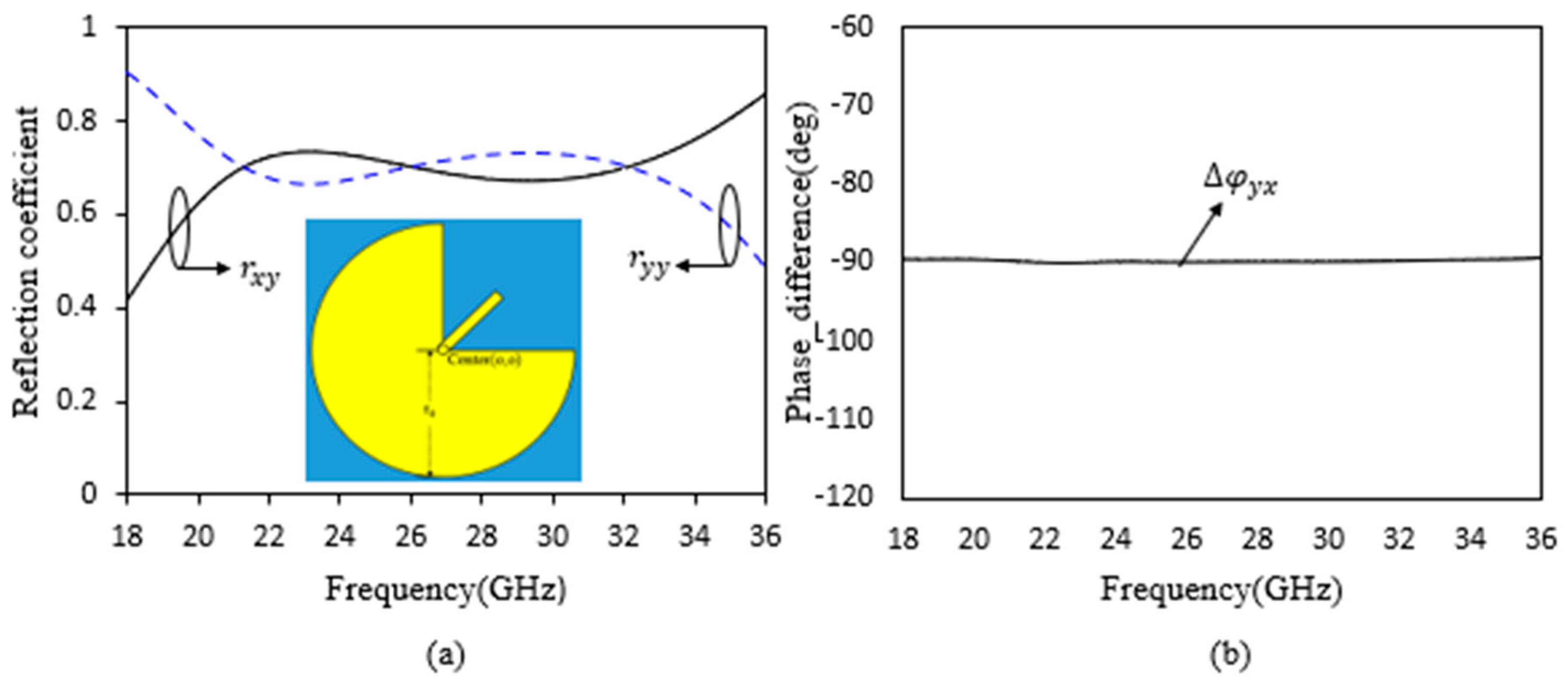
2.1. Stokes Parameters

The Stokes parameters are used to understand the LTC-PC efficiency of the proposed converter. The Stokes parameters [26] are equated as follows:
S 0 = | r y y | 2 + | r x y | 2 S 1 = | r y y | 2 | r x y | 2 S 2 = 2 | r x y | | r y y | cos φ x y S 3 = 2 | r x y | | r y y | sin φ x y
According to the definitions of the Stokes parameters, the mathematical expression of the normalized ellipticity can be determined as e = S 3 / S 0 = ± 1 . For the reflected wave, the normalized ellipticities e = S 3 / S 0 = + 1 and e = S 3 / S 0 = 1 mean LHCP and RHCP, respectively. The frequency-dependent normalized elliptic ratio (ellipticity) can be determined from Figure 2 and Equation (1), as shown in Figure 5a. The normalized ellipticity is approximately −1 in the frequency bands 20.18–33.93 GHz, indicating that the reflected wave is RHCP. To further characterize the circular polarization efficiency, we define tan 2 α = S 2 / S 1 and sin 2 β = S 3 / S 0 , where “ α ” is the rotational angle of the polarization (Azimuthal angle), and “ β ” is the elliptical angle. Figure 5b shows that the elliptical angle is −45° in the frequency bands (20.18–33.93 GHz), indicating that the reflected EM wave is RHCP.

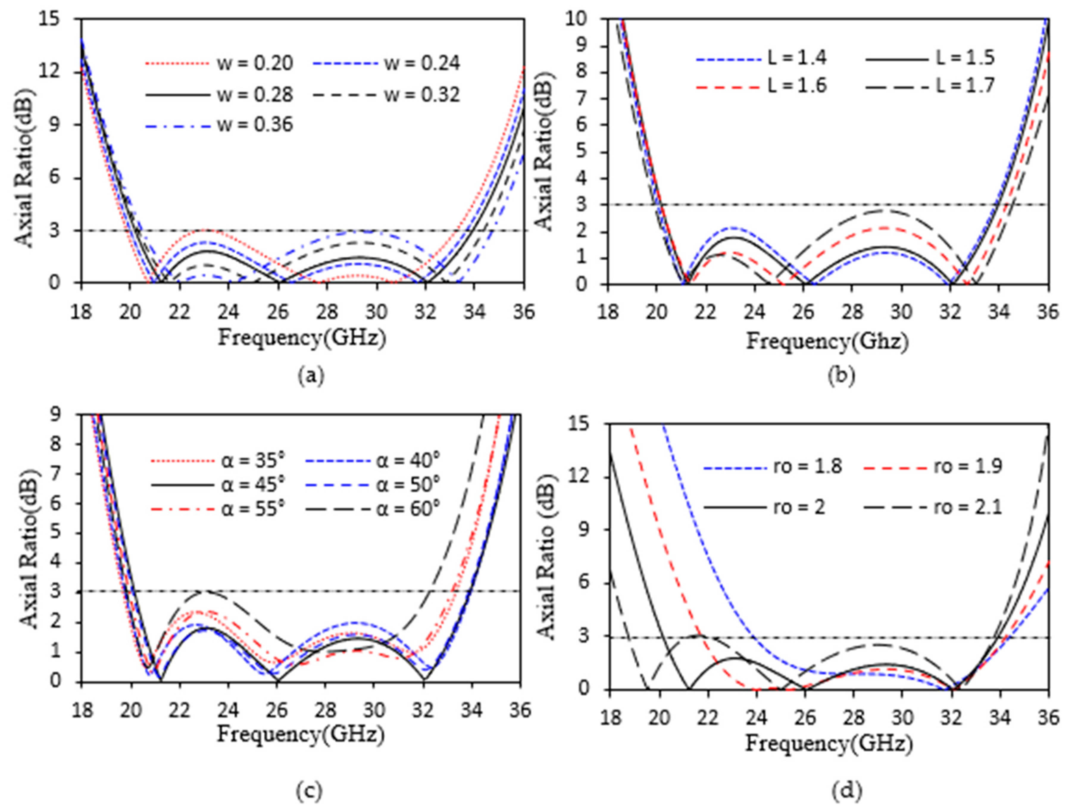
2.2. Parametric Analysis

To learn more about the design, we changed the parameters (α, w, L and r o ) of a circular, pie-shaped embedded rectangular patch to see how the unit cell responds. The details of the parameters are shown in Figure 1. A series of parameter tests are discussed in detail to investigate how the parameters affect the AR of the proposed unit cell when only one parameter changes and other remain constant. The calculated results of the parametric AR are shown in Figure 6. In the higher frquency range, the resonance of the axial ratio is affected by the parameters w and L, as shown in Figure 6a,b. Changing the parameters w and L contribute a little to approach the above-3-dB bandwidth AR in higher frequency bands. As a compromise of the 3-dB axial ratio, the scales of parameters w and L are chosen (0.20 mm-to−0.36 mm and 1.4 mm-to−1.7 mm). The resonance in the lower frequency range is affected by the parameters α and r 0 . Figure 6c,d show the bandwidth of the 3-dB axial ratio after changing the two other parameters microstrip angle α from 35° to 60° and circular radius r 0 from 1.8 mm to 2.1 mm. The response of the 3-dB axial ratio bandwidth for a circular patch radius r 0 from 1.8 mm to 1.9 mm and microstrip angle α from 55° to 60° is distorted. The axial ratio is less than 3-dB when the parameters are varied, which is very interesting to observe. According to the above explanation, our proposed metasurface performs exceptionally well in circular polarization conversion.

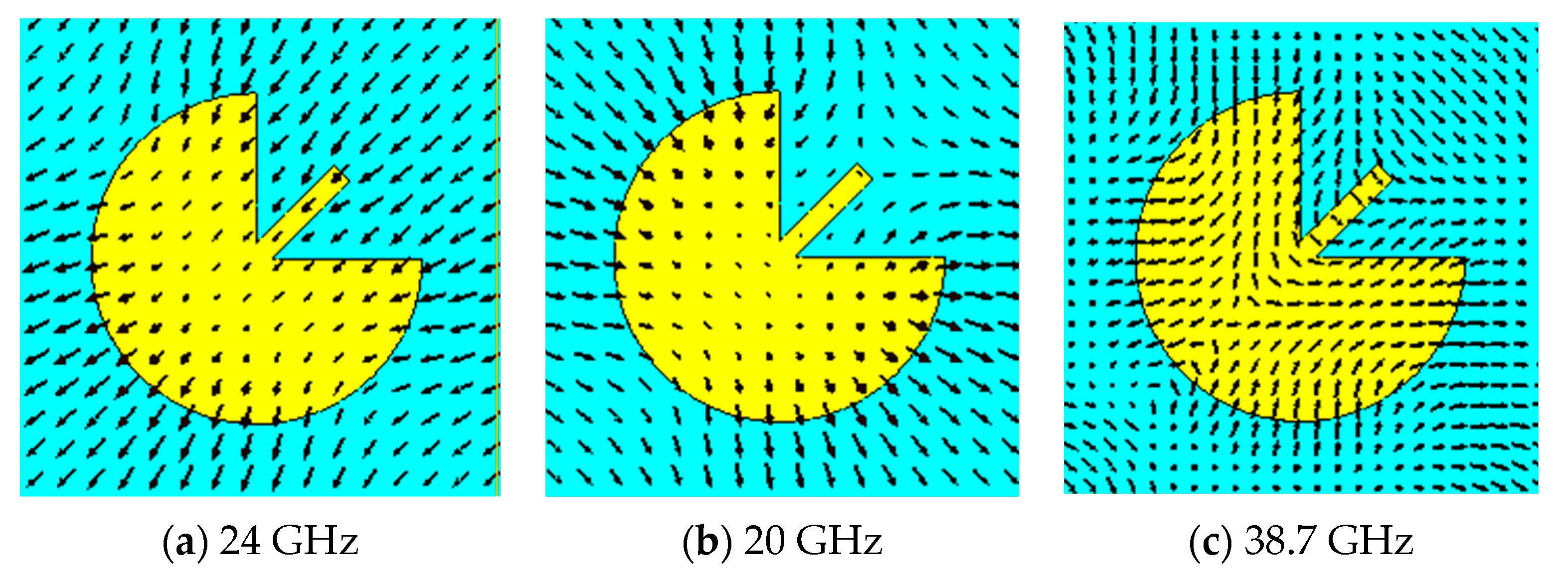
3. Theoretical Analysis

In order to understand the physical configuration of the polarization conversion, we will perform a detailed investigation below. How can the proposed polarization converter perform such a highly efficient and wideband LTC-PC? The reflection matrix (Rlin) at linear polarization (LP) incidence can be equated in the U–V coordinate as follows:
R lin ( LP reflection   matrix ) = ( r u u 0 0 r v v )
Due to the anisotropic structure of the metasurface, the co ( r u u r v v )-polarized reflection coefficients are independent, but their magnitudes are extremely close to 1.0 due to the low dielectric loss. Therefore, the following mathematical equation can be expressed without considering the negligible dielectric loss: r v v = r u u e j φ u v . The phase difference between r v v and r u u , which can be constrained between 180 ° to + 180 ° , is presented by φ u v . The coordinates of the (x and y)-polarized unit wave can be defined as e ^ x = 2 2 ( r u u r v v ) and e ^ y = 2 2 ( e ^ u + e ^ v ) , where U–V coordinates (u and v) are at ±45° to the y-axis for the symmetry axis, respectively. In the coordinate system (X-Y), the Rlin (LP-reflection matrix) can be determined using Equation (2). If the incident wave is assumed to be y-polarized ( E i = E 0 e ^ y = 2 2 ( e ^ u + e ^ v ) ), the total reflected wave can be characterized as follows ( E r = E u r e ^ u + E v r e ^ v ) using the Rlin (reflection matrix) in Equation (2). The total reflected wave can be written after algebraic simplification. E r = E 0 2 [ ( r u u + r v v ) e ^ y + ( r u u r v v ) e ^ x ] . The reflection coefficients of co ( r y y ) and cross ( r x y ) for the y-polarized incident wave can be summarized as follows: r y y = 1 2 ( r u u + r v v ) = 1 2 r u u ( 1 + e j φ u v ) and r x y = 1 2 ( r u u r v v ) = 1 2 r u u ( 1 e j φ u v ) . The final Rlin (reflection matrix) [16] of the coordinate system (X-Y) is obtained as follows after a similar calculation for the x-polarized wave.
R lin = ( r x x r x y r y x r y y ) = 1 2 ( r u u + r v v r u u r v v r u u r v v r u u + r v v ) = 1 2 r u u ( 1 + e j φ u v 1 e j φ u v 1 e j φ u v 1 + e j φ u v )
The following equation can be derived from Equation (3).
r y y r x y = r x x r y x = 1 + e j φ u v 1 e j φ u v = 1 + cos ( φ u v ) j sin ( φ u v ) 1 cos ( φ u v ) + j sin ( φ u v ) = j sin ( φ u v ) 1 cos ( φ u v )
Moreover, the magnitudes of co ( r x x ,   r y y ) and cross ( r x y ,   r y x ) can be written as follows using Equation (4):
| r y y | = | r x x | = 1 2 | r u u | | 1 + e j φ u v | = 1 2 | 1 + cos ( φ u v ) j sin ( φ u v ) | = ( 1 + cos φ u v ) / 2 | r x y | = | r y x | = 1 2 | r u u | | 1 e j φ u v | = 1 2 | 1 cos ( φ u v ) + j sin ( φ u v ) | = ( 1 cos φ u v ) / 2
The reflection coefficients of r y y , r x x - and r x y , r y x -polarization at y- and x-polarized incidences are purely imaginary numbers, as given in Equation (4). The phase difference ( φ u v ) between them is assumed to ±90° in all cases. This explains why the phase difference ( φ y x ) in Figure 2b is always 90 ° in the 18–36 GHz range. The reflection coefficients of the ( r y y , r x x ) and ( r x y , r y x ) polarization will never be zero when ( φ u v 0 °   and   ± 180 ° ) , resulting in an elliptically polarized reflected wave; the φ y x (phase difference) across the ( r y y , r x x ) and ( r x y , r y x )-polarization will always be ±90°. The magnitude ratio of ( r y y , r x y ) and ( r x x , r y x ) is used to calculate the 3-dB AR of the reflected wave, which is:
AR = { | sin ( φ u v ) | 1 cos ( φ u v )         i f   | sin ( φ u v ) |   1 cos ( φ u v )   1 cos ( φ u v ) | sin ( φ u v ) |               i f   | sin ( φ u v ) | < 1 cos ( φ u v )  
Moreover, the relationship r y y r x y = r x x r y x in Equation (4) shows that the ratio of two (x- and y-) polarized reflected factors is identical for x- and y-polarized incidence. According to Equation (5), the polarization condition of the reflected wave is identical to the polarization condition of the incident wave when φ u v = 0 ° is set, and the magnitudes co ( r y x ) and cross ( r x y ) are both zero. When φ u v = 180 ° , on the other hand, | r y y | = | r x x | = 0 , and perfect CPC (cross polarization conversion) is achieved. Moreover, the reflected wave is also elliptically polarized when φ u v 0 °   or   ± 180 ° , according to Equation (5). The AR of the reflected wave [16] can be determined by the following equation:
AR = ( 1 ±   cos φ u v ) / ( 1 cos φ u v )
Here, the combination of subtraction and addition must ensure that the axial ratio is not less than 1.0. When φ u v = 90 ° , the AR of the reflected wave appears to be equal to one, indicating an exact LTC-PC, according to Equations (6) and (7). If φ u v = 90 ° , why can a perfect LTC-PC be achieved? Bypassing the small dielectric loss, the reflected and incident wave at y- and x-polarized incidences can be considered as one synthesis wave with equal amplitude v- and u-polarized components. For the incident wave, the two orthogonal components appear to be in phase, while the phase difference between the two orthogonal components changes for the reflected wave. When φ u v = 90 ° , the phase difference is set to ±90°, resulting in a perfect LTC-PC. According to the above study, we simulated the proposed polarization converter at u- and v-polarized incidences and step-by-step determined the fundamental cause of the LTC-PC. In the frequency band between 20 and 33.90 GHz, the phase difference ( φ u v ) between r v v and r u u remains at +90°, which is consistent with the simulated results in Figure 7. Why is the obtained φ u v so good? To determine the reason, Figure 7b,c show other simulated results, such as the magnitudes of r v v and r u u , as well as their phase variations. The formula φ i i = A r g ( R i i ) + 2 k 0 S was used to quantify their phase fluctuations, where S is the distance between the surface of the polarization converter and Floquet Port in the simulation structure. At all frequencies, the magnitudes of r v v and r u u are close to1.0, as can be seen in Figure 7b. Nevertheless, the simulated graphs of r v v and r u u show some variance, with one and two minimum values at 24, 20 and 38.7 GHz, respectively. There are one and two resonant modes stimulated by u- and v-polarized incidence, respectively, which are the source of these local maximal dielectric losses. Moreover, the curves of the data plots of r v v and r u u are very different at different resonant frequencies, which means that their Q values are different. Since all these resonance approaches have different Q values, the phase variations of r v v or r u u at each resonance frequency are also different, as shown in Figure 7c. When we increase the frequency of the periodicity of the patch, and the response of the reflection phase decreases, the response of the reflection phase will be linear. The resonance frequency and dynamic phase range of the unit cell are affected by changes in “h”. Changing “h” is advantageous because it lowers “transition effects” (also known as “edge effects”), resulting in improved beam-steering performance and the periodicity of the metasurface unit cells, which causes transition or edge effects and degrades the reflected beam. The advantage of changing h (the dielectric substrate thickness) eliminates this problem. Conventional devices (e.g., lenses, holograms, etc.) shape the wavefronts over a distance larger than the operating wavelength. Lenses make use of their shape and the material properties (refractive index) to focus energy by gradually varying the phase of an electromagnetic wave; holograms generate images in the far field through constructive interference. Phase gradient metasurfaces only control phases and manipulate the wave for many useful purposes, in which some of them are mentioned (beam shaping/scanning, lensing, OAM beam generation, waveplates, flat lens, spiral phase plates, broadband absorbers, color printing, polarimeters, surface wave couplers and holograms). Finally, based on the φ u v (phase difference) shown in Figure 7a, we calculated the AR of the reflected wave using Equation (7). The obtained results, which are shown in Figure 7d, indicate that the calculated AR is generally consistent with the results in Figure 3a. The electric field distributions of the three resonant modes in the VZ and UZ longitudinal sections of the proposed polarization converter are determined and shown in Figure 8. The resonant electric fields of the first resonant modes at u-polarized incidences, including the second and third resonant modes at v-polarized incidences, are mainly distributed between adjacent conductor fields in different unit cells. In contrast, the resonant fields of the second two resonant modes are uniformly distributed over the conductor field in each unit cell, and the resonant zones are modest. It is understandable that this type of resonant mode is not generated. Figure 9 represents the surface current distribution for the linear-to-circular polarization conversion at the center frequency (27 GHz). The top patch’s surface current is excited first when the incident electric field is y-polarized; then, the bottom patch’s surface current is induced by the top patch’s surface current. The bottom surface current has a phase delay when compared to the top, which is normal for surface current flow. The reflection of RHCP waves can be achieved when theta shifts from 90° to −90° when the incidence is y-polarized and vice versa. Because of the strong coupling effects between the two metal patches, RHCP conversion has more stability than LHCP conversion. These currents flow in roughly orthogonal directions, one from upright to down left (Jtotal) and the other from down right to up left (Jtotal). To achieve linear-to-circular polarization conversion, the length and width of the rectangular patch embedded with a circular pie shape can be modified appropriately. According to the research beyond, it is clear why PC can achieve high-efficient and ultra-wideband LTC-PC. Table 1 shows the comparison of the proposed metasurface with those of other published work.

4. Conclusions

In summary, an ultrawideband and highly efficient LTC-PC is proposed in this work based on a single layer of a circular, pie-shaped metasurface. Moreover, the proposed reflective metasurface can convert linear incident waves into circular waves with an efficiency of 98% in frequency bands (20–34 GHz), and the relative 3-dB bandwidth is 50.8% over 20.18–33.93 GHz. A rigorous theoretical study is presented to find out the main reason for the LTC polarization conversion. The parametric research results are presented in detail to guide the design. For v- and u-polarized incidences, the φ u v between two reflection coefficients is ±90°, which perfectly predicts the reflected wave AR. When the φ u v approaches nearly ±90°, the metasurface can act as an efficient LTC-PC. The proposed metasurface can be used in antenna design and polarization control devices due to its LTC polarization conversion capability.

Author Contributions

Writing—Original Draft Preparation, A.M.; Writing—Review and Editing, J.Z. and M.S.; Methodology, A.M.; Software, A.M.; Formal analysis, M.A.A.; Validation, K.H.M.; Data Curation, M.I.; Investigation, S.M. All authors have read and agreed to the published version of the manuscript.

Funding

This work was supported by the Fundamental Research Funds for the Central Universities (No. 2019XD-A07), the director Fund of Beijing Key Laboratory of Space-ground Interconnection and Convergence and the National Key Laboratory of Science and Technology on Vaccum Electronics.

Institutional Review Board Statement

Not applicable.

Informed Consent Statement

Not applicable.

Data Availability Statement

Not applicable.

Conflicts of Interest

The authors declare no conflict of interest.

References

  1. Akbari, M.; Farahani, M.; Sebak, A.R.; Denidni, T.A. Ka band linear-to-circular polarization converter based on multilayer slab with broadband performances. IEEE Access 2017, 5, 17927–17937. [Google Scholar] [CrossRef]
  2. Akbari, M.; Gupta, S.; Zarbakhsh, S.; Sebak, A.R. A linear-to-circular polarizer based on frequency selective surface operating 30 GHz applications. In Proceedings of the 2016 17th International Symposium on Antenna Technology and Applied Electromagnetics (ANTEM), Montréal, QC, Canada, 10–13 July 2016; IEEE: Piscataway, NJ, USA, 2016; pp. 1–2. [Google Scholar]
  3. Guariglia, E. Entropy and Fractal antennas. Entropy 2016, 18, 84. [Google Scholar] [CrossRef]
  4. Krzysztofik, W.J. Fractal geometry in electromagnetics applications from antenna to metamaterials. Microw. Rev. 2013, 1, 19. [Google Scholar]
  5. Hohlfed, R.G.; Cohen, N. Self-similarity and the geometric requirements for frequency independence in antennae. Fractals 1999, 7, 79–84. [Google Scholar] [CrossRef]
  6. Al-Gburi, A.J.A.; Ibrahim, I.B.M.; Zakaria, Z.; Ahmad, B.H.; Bin Shairi, N.A.; Zeain, M.Y. High gain of UWB Planar antenna utilizing FSS reflector for UWB applications. Comput. Mater. Contin. 2022, 70, 1419–1436. [Google Scholar] [CrossRef]
  7. Askari, H.; Hussain, N.; Choi, D.; Abu Sufian, M.; Abbas, A.; Kim, N. An AMC-based circularly polarized antenna for 5G sub-6 GHz communications. Comput. Mater. Contin. 2021, 69, 2997–3031. [Google Scholar] [CrossRef]
  8. Munk, B.A. Frequency Selective Services: Theory and Design; Wiley: New York, NY, USA, 2000. [Google Scholar]
  9. Hwang, K.C. A novel meander-grooved polarization twist reflector. IEEE Microw. Wirel. Compon. Lett. 2010, 20, 217–219. [Google Scholar] [CrossRef]
  10. Chen, H.; Ma, H.; Qu, S.; Wang, J.; Li, Y.; Yuan, H.; Xu, Z. Ultra-wideband polarization conversion metasurfaces. In Proceedings of the 2014 3rd Asia-Pacific Conference on Antennas and Propagation, Harbin, China, 26–29 July 2014; pp. 1009–1011. [Google Scholar]
  11. Yu, X.Y.; Gao, X.; Han, X.; Li, S.M.; Cao, W.P.; Yu, X.H.; Jiang, Y.N. High-performance terahertz polarization converter based on double V-shaped metasurface. IEEE Trans. Antennas Propag. 2015, 63, 3522–3530. [Google Scholar]
  12. Zhao, J.; Cheng, Y. A High efficiency and broadband reflective 90° linear polarization rotator based on anisotropic metamaterial. Appl. Phys. 2016, 122, 225. [Google Scholar] [CrossRef]
  13. Lin, B.Q.; Da, X.Y.; Wu, J.L.; Wi, L.; Fang, Y.W.; Zhu, Z.H. Ultra-wideband and high efficiency cross polarization converter based on anisotropic metasurface. Microw. Opt. Tech. Lett. 2016, 58, 2402–2405. [Google Scholar] [CrossRef]
  14. Zhu, H.L.; Cheung, S.W.; Chung, K.L.; Yuk, T.I. linear-to-circular polarization conversion using metasurface. IEEE Trans. Antennas. Propag. 2013, 61, 4615–4623. [Google Scholar] [CrossRef] [Green Version]
  15. Chen, H.; Wang, J.; Ma, H.; Qu, S.; Xu, Z.; Zhang, A.; Yan, M.; Li, Y. Ultra-wideband polarization conversion metasurfaces based on multiple plasmon resonances. J. Appl. Phys. 2014, 115, 154504. [Google Scholar] [CrossRef]
  16. Kaouach, H.; Dussopt, L.; Lanteri, J.; Koleck, T.; Sauleau, R. Wideband low-loss linear and circular polarization transmit-arrays in V-band. IEEE Trans. Antennas Propag. 2011, 59, 2513–2523. [Google Scholar] [CrossRef]
  17. Yu, N.; Aieta, F.; Genevet, P.; Kats, M.A.; Gaburro, Z.; Capasso, F. A broadband, background-free quarter-wave plate based on plasmonic metasurfaces. Nano. Lett. 2012, 12, 6328–6333. [Google Scholar] [CrossRef]
  18. Wang, L.; Hu, H.; Liu, K.; Jiang, S.; Zeng, W.; Gan, Q. Polarization management of terahertz extraordinary optical transmission through ultracompact L-shaped subwavelength patterns on metal films. Plasmonics 2014, 8, 733–740. [Google Scholar] [CrossRef]
  19. Martinez-Lopez, L.; Rodriguez, J.; Maetinez-Lopez, J.I.; Martynyuk, A.E. A multilayer circular polarizer based on bisected split-ring frequency selective surfaces. IEEE Antennas Wirel. Propag. Lett. 2013, 13, 153–156. [Google Scholar] [CrossRef]
  20. Tamayama, Y.; Yasui, K.; Nakanishi, T.; Kitano, M. A linear-to-circular polarization converter with half transmission and half reflection using a single-layered metamaterial. Appl. Phys. Lett. 2014, 105, 021110. [Google Scholar] [CrossRef] [Green Version]
  21. Li, Y.; Zhang, J.; Qu, S.; Wang, J.; Zeng, L. Achieving wide-band linear-to-circular polarization conversion using ultra-thin bi-layered metasurfaces. J. Appl. Phys. 2015, 117, 011129. [Google Scholar] [CrossRef]
  22. Lin, B.-Q.; Liv, L.; Guo, J.-X.; Wang, Z.; Huang, S.-Q.; Wang, Y.-W. Ultra-wideband linear-to-circular polarization conversion metasurface. China Phys. B 2020, 29, 104205. [Google Scholar] [CrossRef]
  23. Chazizadeh, M.H.; Dadashzadeh, G.; Korshidi, M. A novel wideband electromagnetic band gap structure for circular polarization conversion. In Proceedings of the 2012 15 International Symposium on Antenna Technology and Applied Electromagnetics, Toulouse, France, 25–28 June 2012. [Google Scholar]
  24. Doumanis, E.; Goussetis, G.; Gomez-Tornero, J.L.; Cahil, R.; Fusco, V. Anisotropic impedance surface for linear to circular polarization conversion. IEEE Trans. Antennas Propag. 2012, 60, 212–219. [Google Scholar] [CrossRef]
  25. Moroya, T.; Makino, S.; Hirota, T.; Noguchi, K.; Itoh, K.; Ikarashi, K. Polarization conversion reflector using a metal-plate-loaded meander line. In Proceedings of the 2014 International Symposium on Antennas and Propagation Conference, Kaohsiung, Taiwan, 2–5 December 2014. [Google Scholar]
  26. Xia, R.; Jing, X.; Gui, X.; Tian, Y.; Hong, Z. Broadband terahertz half-wave plate based on anisotropic polarization conversion metamaterials. Opt. Mater. Express. 2017, 7, 977–988. [Google Scholar] [CrossRef]
  27. Li, F.; Chen, H.; Zhang, L.; Zhou, Y.; Xie, J.; Deng, L.; Harris, V.G. Compact high-efficiency broadband metamaterial polarizing reflector at microwave frequencies. IEEE Trans. Microw. Theory Tech. 2018, 67, 606–614. [Google Scholar] [CrossRef]
  28. Long, F.; Yu, S.; Kou, N.; Zhang, C.; Ding, Z.; Zhang, Z. Efficient broadband linear polarization conversion metasurface based on %-shape. Microw. Opt. Tech. Lett. 2020, 62, 226–232. [Google Scholar] [CrossRef]
  29. Zheng, Q.; Guo, C.; Vandenbosch, G.A.; Yuan, P.; Ding, J. Ultra-broadband and high-efficiency reflective polarization rotator based on fractal metasurface with multiple plasmon resonances. Opt. Commun. 2019, 449, 73–78. [Google Scholar] [CrossRef]
  30. Yan, M.; Wang, J.; Pang, Y.; Xu, C.; Chen, H.; Zheng, L.; Zhang, J.; Qu, S. An FSS-backed dual-band reflective polarization conversion metasurface. IEEE Access 2019, 7, 104435–104442. [Google Scholar] [CrossRef]
  31. Zhao, J.; Cheng, Y.Z.; Cheng, Z. Design of a photo-excited switchable broadband reflective linear polarization conversion metasurface for terahertz waves. IEEE Photonics J. 2018, 10, 1–10. [Google Scholar] [CrossRef]
  32. Jiang, Y.; Wang, L.; Wang, J.; Akwuruoha, C.N.; Cao, W. Ultra-wideband high-efficiency reflective linear-to-circular polarization converter based on metasurface at terahertz frequencies. Opt. Express. 2017, 25, 27616–27623. [Google Scholar] [CrossRef]
  33. Ma, H.F.; Wang, G.Z.; Kong, G.S.; Cui, T.J. Broadband circular and linear polarization conversions realized by thin birefringent reflective metasurfaces. Opt. Mater. Express. 2014, 4, 1717–1724. [Google Scholar] [CrossRef]
  34. Jia, Y.; Liu, Y.; Zhang, W.; Wang, J.; Wang, Y.; Gong, S.; Liao, G. Ultra-wideband metasurface with linear-to-circular polarization conversion of an electromagnetic wave. Opt. Mater. Express. 2018, 8, 597–604. [Google Scholar] [CrossRef]
  35. Li, S.; Zhang, X. An ultra-wideband linear-to-circular polarization converter in reflection mode at terahertz frequencies. Microw. Opt. Tech. Lett. 2019, 61, 2675–2680. [Google Scholar] [CrossRef]
  36. Jiang, S.C.; Xiong, X.; Hu, Y.S.; Hu, Y.H.; Ma, G.B.; Peng, R.W.; Sun, C.; Wang, M. Controlling the polarization state of light with a dispersion-free metastructure. IEEE Phys. Rev. X 2014, 4, 021026. [Google Scholar] [CrossRef] [Green Version]
  37. Zhang, Z.; Cao, X.; Gao, J.; Li, S. Broadband metamaterial reflectors for polarization manipulation based on cross/ring resonators. Radioengineering 2016, 25, 436–441. [Google Scholar] [CrossRef]
  38. Mao, C.; Yang, Y.; He, X.; Zheng, J.; Zhou, C. Broadband reflective multipolarization converter based on single-layer double-L-shaped metasurface. Appl. Phys. A 2017, 123, 767. [Google Scholar] [CrossRef] [Green Version]
  39. Zheng, Q.; Guo, C.; Ding, J. Wideband metasurface-based reflective polarization converter for linear-to-linear and linear-to-circular polarization conversion. IEEE Antennas Wirel. Propag. Lett. 2018, 17, 1459–1463. [Google Scholar] [CrossRef]
  40. Gao, X.; Yu, X.Y.; Cao, W.P.; Jiang, Y.N.; Yu, X.H. Ultra-wideband circular-polarization converter with micro-split Jerusalem-cross metasurfaces. Chin. Phys. B 2016, 25, 128102. [Google Scholar] [CrossRef]
  41. Lin, B.; Wu, J.-L.; Da, X.-Y.; Li, W.; Ma, J.-J. A linear-to-circular polarization converter based on I-shaped circular frequency selective surfaces. Appl. Phys. A Solids Surf. 2017, 123, 43. [Google Scholar] [CrossRef]
Figure 1. A 2-D front view of circular, pie-shaped metasurface with structural parameters (unit: mm, r0 = 2, α = 45°, w = 0.28, L = 1.5, h = 1.6 and t = 0.017): (a) circular pie shape embedded with rectangular patch and (b) side view with substrate properties.
Electronics 11 01681 g001
Figure 2. The simulated results of proposed metasurface: (a) r y y   and   r x y and (b) phase diffe-ence φ y x (degree).
Electronics 11 01681 g002
Figure 3. The calculated results of a circular pie shape embedded with rectangular patch: (a) axial ratio (AR) and (b) r R H C P y and r L H C P y .
Electronics 11 01681 g003
Figure 4. The calculated results of LTC polarization reflection coefficient: (a) PCR and (b) PER.
Electronics 11 01681 g004
Figure 5. The calculated results of LTC polarization reflection coefficient: (a) ellipticity and (b) elliptical angle (deg).
Electronics 11 01681 g005
Figure 6. The calculated results of axial ratio vary at different parameters: (a) w (0.20 mm–0.36 mm); (b) L (1.4 mm–1.7 mm); (c) α (35°–60°) and (d) ro (1.8 mm–2.1 mm).
Electronics 11 01681 g006
Figure 7. The simulated results of uv polarized incident wave: (a) phase difference ( φ u v ); (b) the magnitudes ( r v v   and   r u u ); (c) phase variations and (d) the axial ratio of the reflected wave.
Electronics 11 01681 g007
Figure 8. The electric field distribution of different resonant modes: (a) the first resonant mode at u-polarized incidence (24 GHz); (b) v-polarized incidence (20 GHz) and (c) v-polarized (38.7 GHz).
Electronics 11 01681 g008
Figure 9. Induced surface current distribution on top and grounded metal parts at center frequency (27 GHz) of linear-to-circular polarization conversion.
Electronics 11 01681 g009
Table 1. Comparison of polarization converter with the previous published works.
RefsFrequency
Band (GHz)
Unit Cell (P)ThicknessPerformanceFBW (%)PCR
[33]9.50–11.006.0 mm3 mmLP to CP15.0N/A
[37]11.5–15.613.2 mm4 mmLP to CP30.3N/A
[38]18.1–22.56.4 mm2.2 mmLP to CP36.31N/A
[39]13.70–15.608.1 mm3.1 mmLP to CP13N/A
[40]12.4–21.05.0 mm2.5 mmLP to CP50N/A
[41]5.86–7.3412.0 mm1.8 mmLP to CP18.9N/A
This work20.18–33.936.0 mm1.6 mmLP to CP50.898
Publisher’s Note: MDPI stays neutral with regard to jurisdictional claims in published maps and institutional affiliations.

