Article

A Path Planning Strategy of Wearable Manipulators with Target Pointing End Effectors

1
School of Mechanical Engineering, Nanjing University of Science and Technology, Nanjing 210094, China
2
No.208 Research Institute of China Ordnance Industries, Beijing 102202, China
*
Author to whom correspondence should be addressed.
Electronics 2022, 11(10), 1615; https://doi.org/10.3390/electronics11101615
Submission received: 17 March 2022 / Revised: 24 April 2022 / Accepted: 29 April 2022 / Published: 19 May 2022

Abstract

:
End effectors like firearms, cameras and fire water guns can be classified as pointing end effectors. When installed on wearable manipulators, a new function can be given to the wearer. Different from gripper end effectors (GEEs), target pointing end effectors (TPEEs) have different working tasks, and the requirements for path planning are also different. There is very limited research on wearable manipulators with TPEEs. Meanwhile, manipulator with GEE path planning tends to be mature, but with a relatively low efficiency concerning its algorithm in solving high-dimensional problems. In this paper, a degree of freedom (DOF) allocation scheme and a path planning strategy (unlike manipulator with gripper end effector) were proposed for manipulators with a target pointing end effector in order to reduce the difficulty of path planning. Besides, this paper describes a new algorithm-dimension rapid-exploration random tree (dimension-RRT) to divide the manipulator DOFs into groups and unify DOFs groups by adding a fake time. The dimension-RRT was compared with the rapid-exploration random tree star algorithm (RRT*) in the same simulation environment; when there are 500 random points, the dimension-RRT time consumption is 0.556 of RRT* and the path length is 0.5 of RRT *. To quickly obtain a path that can avoid the human body, dynamic movement primitives (DMPs) were used to simulate typical spatial motion path and obstacle avoidance path efficiently.

1. Introduction

As an effective substitute to human beings, manipulators have found a wide application in aviation, mechanical and military industries. Seamless function switches can be implemented through modularized manipulator end effectors. A selection of task-specific end effectors brings about a quick operation adaptation. At present, manipulator developments are limited within the range of GEEs in the replacement of human manipulation tasks, such as grasping, picking, processing, supporting and so on [1,2,3,4].
Previous achievements center on manipulators carrying GEEs which are fixed around the human body to assist people or around a base to complete tasks independently within a certain range. In these tasks, manipulator end effectors need to physically contact the task targets. By contrast, TPEEs in this research aimed at an orientation or a trajectory line toward the target point. The manipulator with TPEE is designed to control its orientation toward the target, and then to perform aiming, shooting, exploration or other tasks, as those used in firearms, fire water guns, laser guns, searchlights, photography machines, etc. Thus, there is a largely expanded manipulator operation range. As is often the case, manipulators with TPEE bases are either built in a vehicle or located in a relatively open and barrier free position; one to two DOFs are sufficient for the target pointing end and large-scale tracking and aiming. As the wearable equipment is becoming increasingly lightweight, professional, diversified and dimensionalized, the physical operation ranges and types are further extended for solo missions. TPEEs are expected to take the lead in wearable manipulators by promising more potential applications for wearable equipment. The fact that most TPEEs are still operated by the wearer and fail to complete an independent task reveals inadequate study of TPEEs [5,6]. Manipulator performances can be effectively improved by designing robot arm path planning strategies and specific methods corresponding to different end effector types. While traditional manipulator path planning methods with GEEs are applicable to most manipulators, they cannot be readily applied to TPEEs. Different in operation tasks, GEEs need to approach and contact the target point with a certain attitude, while TPEEs need their extension lines or trajectories to pass through the target point. A mere copy of the traditional manipulator algorithm and structural forms would complicate path planning with increased DOFs, flexibility and inverse kinematics solutions. If the solution is narrowed down to the obstacle avoidance process of the manipulator body, factors such as blocking in the pointing direction will be ignored. This research focused on robotics was thus targeted at an effective reduction of the manipulator path planning difficulty [7]. A new path planning algorithm for TPEEs will be discussed in this paper, which can effectively reduce the path planning difficulty of wearable manipulators on the premise of ensuring functions.
RRT is a sampling-based algorithm, it can quickly expand a tree like path to explore most areas of space and wait for opportunities to find a feasible path, as proposed by Steven in 1998 [8]. However, the RRT algorithm ends when it finds the first path, and usually cannot obtain the optimal solution. Various algorithms have been proposed to enhance the original RRT algorithm. As the number of iterations approaches infinity, RRT*, proposed by Sertac Karaman in 2011, is able to continue optimizing the initial path in successive iterations and obtain an optimal or near optimal path to the target [9]. For faster initial path finding, Jordan proposed the bidirectional rapidly exploring random tree algorithm (Bi-RRT*) in 2013, which can provide solutions rapidly in planning problems by improving utilization efficiency of samplings [10]. The informed-RRT*, proposed by Jonathan D. Gammell in 2014, sets a hyper-ellipsoid whose focal points are initial state and the goal state once one path is found, while the new states generated in the ellipsoid make it possible to optimize the path [11]. Binghui Li and Badong Chen proposed a new improved algorithm called adaptive RRT-Connect (ARRT-Connect) in 2022, where bidirectional search like Bi-RRT was applied. In ARRT-connect, a new sampler is designed for the sampling process; the type judging process of local environments is simplified [12]. For better performance in the initial cost solution, convergence time, and the number of nodes visited, directional RRT*(D-RRT*) was proposed to focus on the direction of the goal from the starting configuration through a simple elliptical heuristic, which is different from informed RRT* [13]. In 2022, inspired by the sparse A* and the improved evolutionary algorithms, flight cost-based rapidly-exploring random tree star (FC-RRT*) was proposed. FC-RRT* uses heuristic information to guide the expansion of the tree node, which extends RRT* to deal with the safety requirements and flight constraints of UAVs in a complex 3D environment [14]. RRT and its improved algorithms are widely used in path planning of manipulators, UAVs, unmanned vehicles [13,14,15,16,17,18,19,20,21]. In the mentioned algorithms, RRT and RRT* are improved by guiding the growth direction of random tree, improving utilization efficiency of samples, reducing the sampling space, etc. However, when solving a multi-dimensional environment like a 3D environment or configuration space of manipulators, the solution efficiency decreases. Therefore, how to efficiently solve high-dimensional variables becomes much more significant and is regarded as a key to improving RRT.
In this paper, after a new DOF allocation set scheme, a path planning strategy was designed to simplify the issue for wearable manipulators with TPEEs. A new path planning method named dimension rapid-exploration random tree (dimensions-RRT) is proposed with a reference to the rapid-exploration random tree (RRT) sampling principle and its optimization algorithm rapid-exploration random tree (RRT*) and informed RRT*. This algorithm can simplify the path planning problem by decomposing the high-dimensional problem into multiple low-dimensional problems. To unify the low-dimensional paths, a fake time dimension is added in the algorithm. Then dimension-RRT can optimize the paths in low dimensions and quickly obtain high-quality paths. To solve more complex paths, the DMP algorithm accomplished the omni-directional real-time aiming and tracking of the wearable manipulator with TPEE.

2. Degree of Freedom Allocation Scheme of Wearable Target Pointing End Effector Manipulators

Comparing the existing structures of wearable manipulators, it is found that, due to different operation tasks, the structural schemes of wearable manipulator with a GEE is not suitable for those with TPEE. This chapter proposed a corresponding calculation and DOF distribution scheme according to the functional characteristics of wearable manipulators with TPEEs.

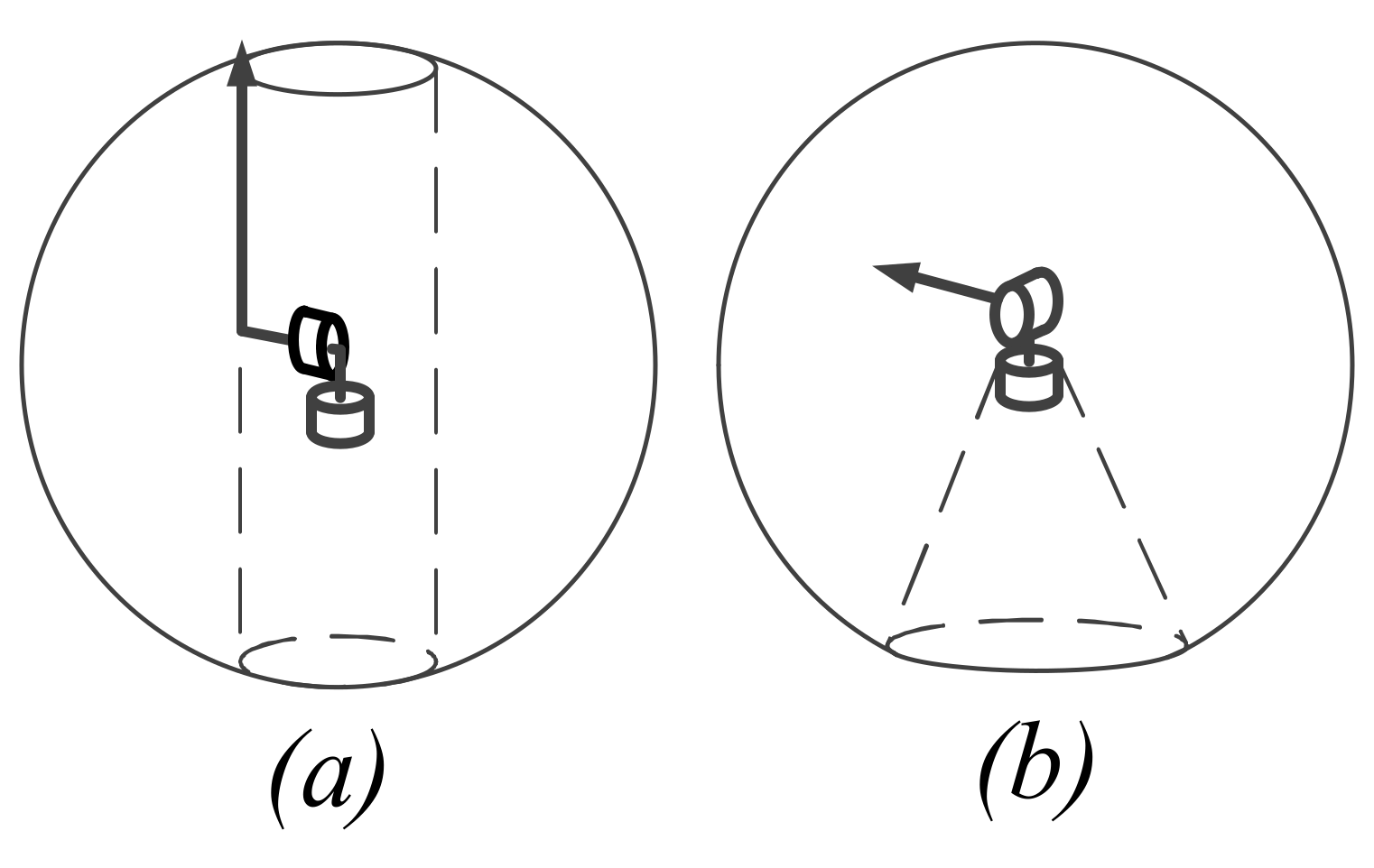
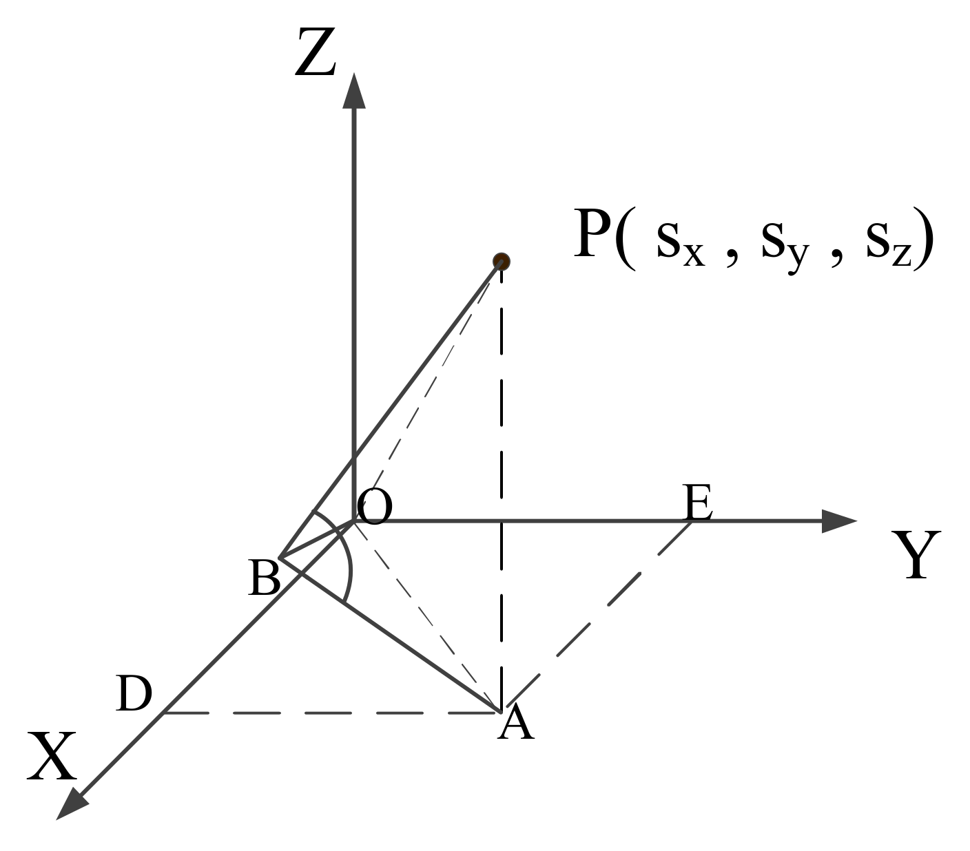
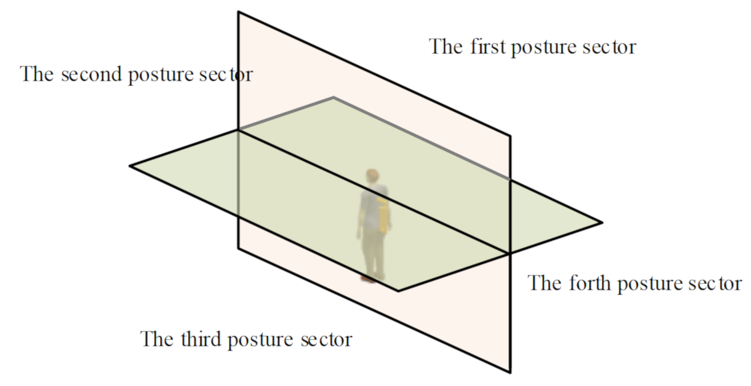
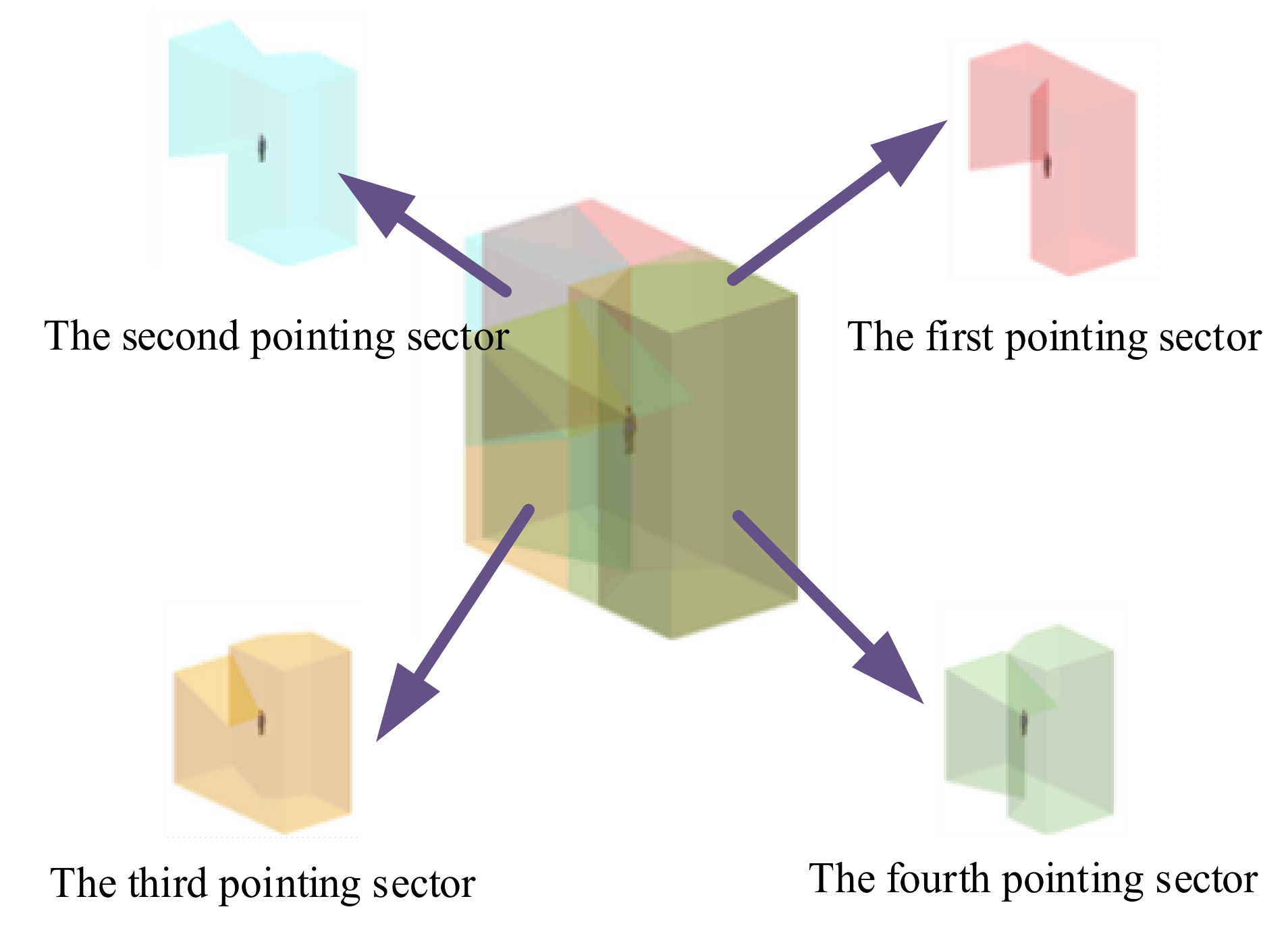
2.1. Problem Description (Target Pointing End Effector Task Description)

Wearable manipulators with TPEE have their peculiarity in path planning and DOF allocation. In terms of task requirements, the TPEE requires the following: 1. No collision in the operation process is allowed between the manipulator and the human body except the connecting part, and obstacles must be strictly avoided between the end effector and the target point. 2. End effectors must constantly face their locked targets, and quickly plan a new path and resume the tracking even if the target enters a blind area. 3. It can quickly give up an original target and lock a new one. Since the chief aim is at the path planning problem of wearable manipulators with TPEE, this paper did not consider the environmental factors outside the obstacles and the impact of special tasks performed by the end effector system after aiming, such as that of shooting on the aiming accuracy. Here, the manipulator posture is defined as the target posture when the target point is on the extension line of the end effector.

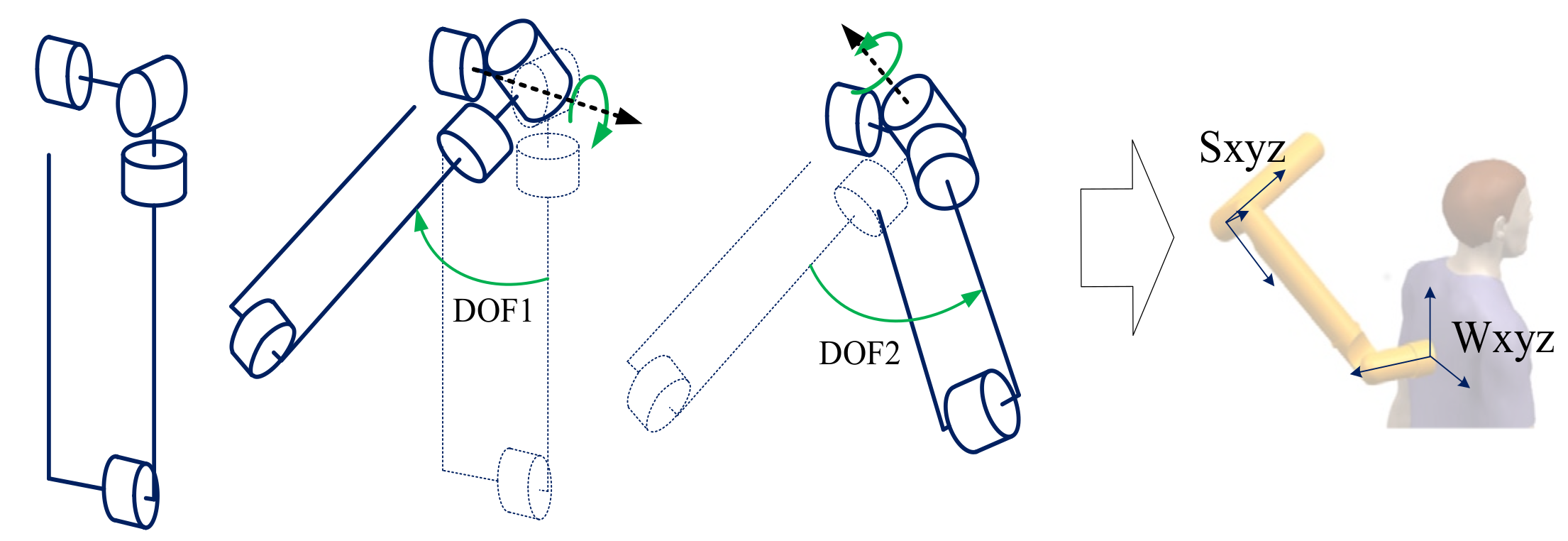
2.2. The Degree of Freedom Assignment Scheme

A strict posture is required for manipulators with GEEs because they need to extend the end effector to the target position. Besides giving certain DOFs to the end effector, two DOFs will be arranged at the arm near the end effector, and their rotation axes are designed to be parallel to each other [22,23,24], as is shown in Figure 1.
These two DOFs can ensure that if other DOFs remain unchanged, the end effectors can be sent to all points that meet the joint structure constraints in the plane of the current manipulator, but obviously this ability has no significance for the end of the TPEEs. Once the target point is in its pointing direction, the end effectors would initiate the task. Thus, a reduction in the DOFs for relevant manipulators is realized.
As a certain length is demanded for TPEE to guide the movement of projectiles and provide acceleration or enabling distance, space utilization and self-collision also need to be taken into account during manipulator movement. The structures need to be as concise as possible. Referring to the existing TPEEs [25,26,27,28,29], the end effectors in this paper were given two DOFs to achieve large-scale aiming. Considering the motor installation and TPEE structure styles, there are two combination schemes of the two DOFs, as shown in Figure 2.
In the above two combination schemes, their pointing blind area in Figure 2b will become larger with the increase of the distance from the target, and the combination scheme is not convenient storage and portability. Because the target points in TPEE tasks are usually located far away from end effectors, the blind area of Figure 2a is smaller than that of Figure 2b and the DOF combination scheme in Figure 2a is selected. Extra requirements would be exerted on the end effectors installed on the manipulator, considering the different tasks. For example, it needs to automatically avoid obstacles in the pointing direction, or to adjust the end effector position when the target is located in the blind area. Therefore, the end effector needs to be given two rotational DOFs to move in the space. In order to ensure the overall weight of wearable equipment is as light as possible and the manipulator is sufficiently flexible, the number of overall motors of the equipment should be as small as possible. In this case, this paper proposed a 4-DOF wearable manipulator with TPEE, whose third and fourth DOFs were applied to ensure that the end effector can point to all directions in the space. Meanwhile, its first and second DOFs are responsible for adjusting the spatial position of the TPEE. The DOF distribution scheme is shown in Figure 3.
In Figure 3, L4 was an end effector; L3 pushed the end effector out a distance to ensure that the TPEE can rotate freely without collision. The kinematic modeling of the DOF scheme was carried out by the D-H method. In order to calculate the feasible manipulator workspace, the TPEE was regarded as a translational DOF to build a five-degrees-of-freedom manipulator. The feasible manipulator workspace was solved by the Monte Carlo method, as shown in Figure 4.
The blue points in the figure represent the space positions that can be reached by the end of the 5-DOF manipulator model, which corresponds to the space position of the target point that the manipulator can point to in the space. It proved that this structural form fully meets the omni-directional work requirements. Among other schemes, this is the minimum DOF design scheme that can meet the omni-directional pointing requirements while the wearer is in a stationary state.

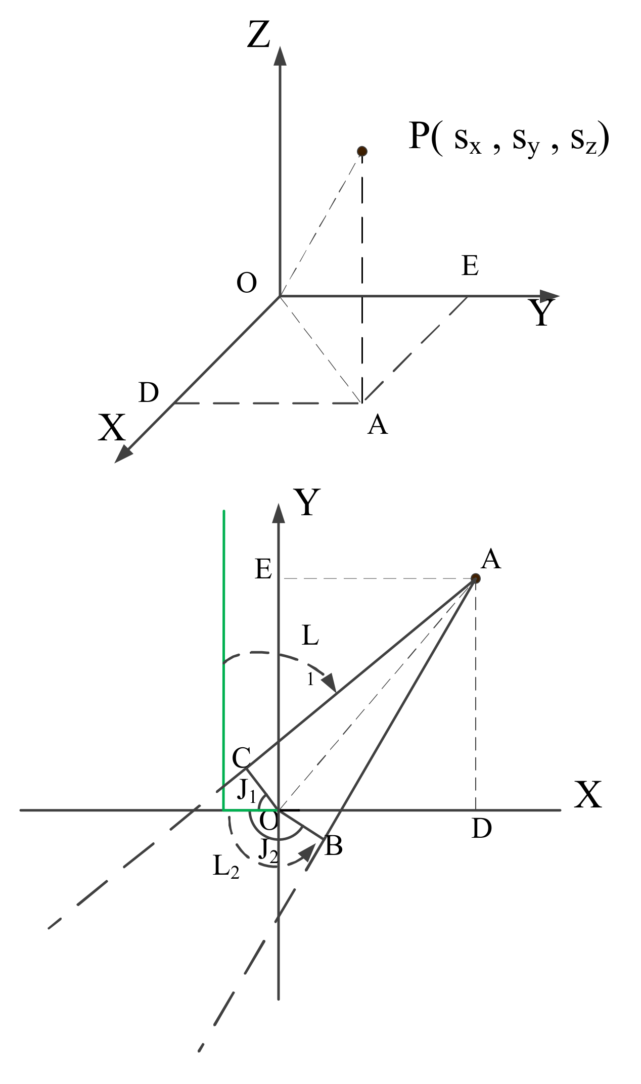
2.3. Inverse Kinematics Calculation of Four-Degrees-of-Freedom Manipulator with the Target Pointing End Effector

The manipulator kinematics is usually analyzed by the D-H model, and the inverse kinematics operation can be completed through the analytical method or Matlab Robotic toolbox. However, when this model is applied to the manipulator with TPEE, the end effector of the manipulator does not have to make contact with the target point, as the task has changed. It is necessary to add a translational DOF at the end effector to represent the distance from the end effector to the target point, which is a complication of the inverse kinematics problem of manipulators with TPEE, while the planning of this DOF is meaningless in practice. Considering that the TPEE can complete the large-scale pointing task with two DOFs, this paper simplified the path planning problem of wearable manipulators with TPEE. Considering the human body as the main obstacle in the wearable manipulator, the space was divided into multiple spaces called posture sectors. The first and second DOFs in posture sectors were clearly set (described in detail later). Combined with the data of the first two DOFs, an inverse kinematics calculation was completed, whose method is as follows.
The two DOFs at the end effector are regarded as a whole with the end effector, which is hereinafter referred to as the pointing system, as shown in Figure 5. When the target coordinate in the world coordinate system Wxyz is obtained, the information of the posture sector is obtained and used to determine the rotation data of the first two DOFs corresponding to the posture sector. Combined with the angles of the first two DOFs, the coordinate position target in Sxyz can be obtained.
The calculation process is as follows:
W x y z = x , y , z T
R x = 1 0 0 0 cos D O F 1 sin D O F 1 0 sin D O F 1 cos D O F 1
R y = cos D O F 2 0 sin D O F 2 0 1 0 sin D O F 2 0 cos D O F 2
M = R x · R y
T = 154.5 0 468 T
S x y z = W x y z · M T
DOF1 and DOF2, respectively, represent the motion amounts of the first and the second DOF. The value of matrix T comes from the specific structural design. In the pointing system coordinate system, the target point is projected to the XOY plane, as shown in Figure 6.
In the above figure, the short green line is the initial position of the end effector in the pointing system, while the long green line is a segment in the end effector direction. The third DOF of the manipulator rotates J2 or J1 angle so that the target point is in the plane which can pass through the long green line and perpendicular to the short green line. Accurate data of arccos l O C / l A O can be obtained through Equations (8) and (9) in combination with the interval in which interval point A is located.
J A O D = arctan y s x s
J 1 = arccos l O C / l A O + J A O D π
J 2 = arccos l O B / l A O + J A O D π
Because the value range of arctan is [−pi, pi], the value of JAOD shall be adjusted according to the interval where the target point is located; JAOD is the angle between the target point and the x axis in the coordinate system XOY plane. The smaller rotation angle in J1 J2 will be selected as the motion data of the third DOF, and then the fourth DOF will be calculated, as shown in Figure 7.
The data of the fourth DOF refer to JPBA, which is obtained by the following formula:
J PBA = arctan s z / l A B
J AB = s x 2 + s y 2 + l O B
The complete data of four DOFs obtained above will be used as the target posture of path planning problem. The path planning strategy for the wearable manipulator with TPEE will be discussed in detail as follows.

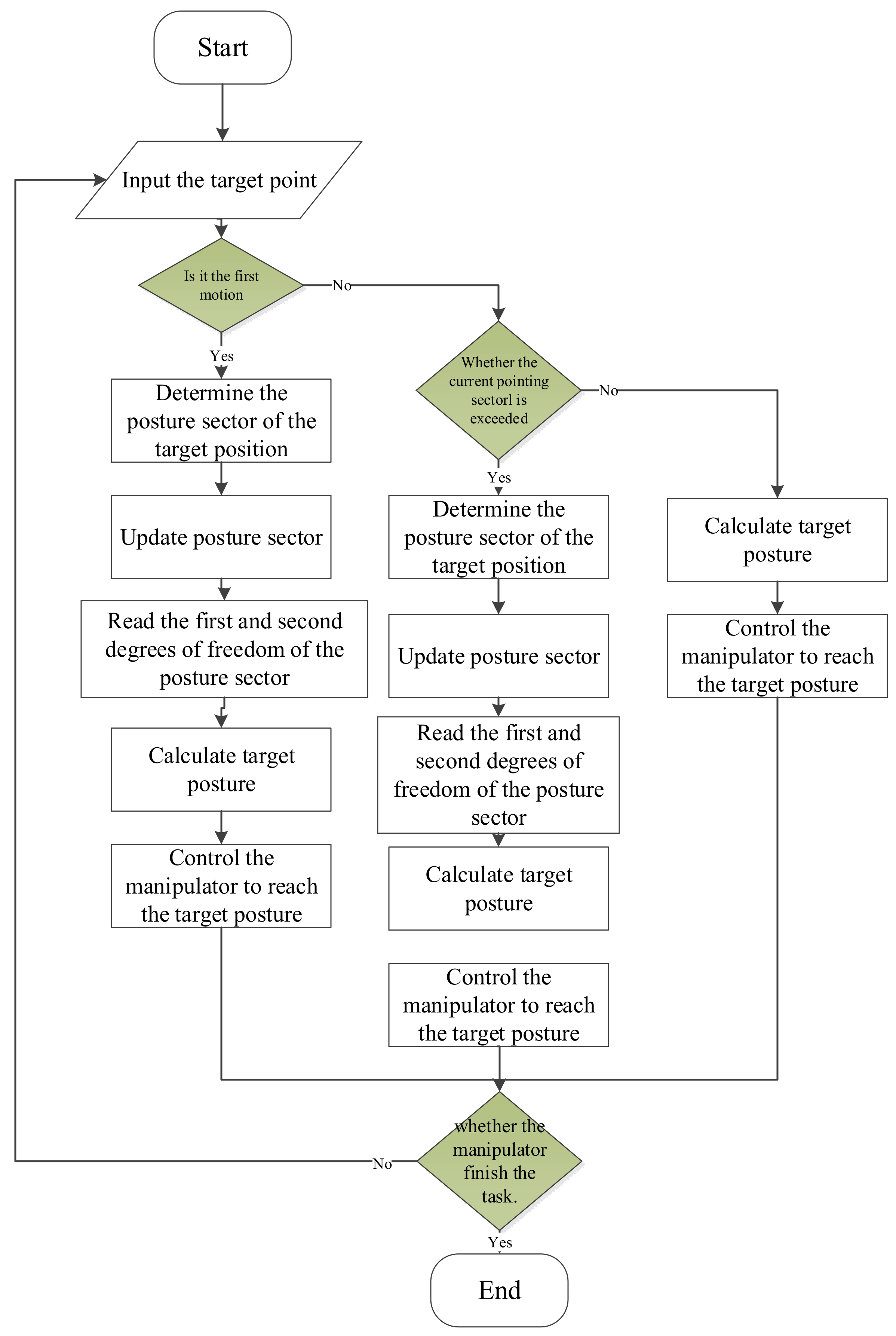
3. A Path Planning Strategy of Target Pointing End Effector Wearable Manipulators

Because the wearable manipulator with the TPEE cooperates with a human wearer, collision with or hindrance by the human body in the movement process should be avoided. The traditional path planning algorithm will consume part of the calculation amount in collision detection. In addition, the calculation difficulty of various path planning algorithms rose with the increase of the input data dimension, i.e., the number of DOFs. By reasonably reducing the number of DOFs involved in the calculation or deconstructing, the manipulator can effectively improve the calculation efficiency. Considering the TPEEs, it is meaningless to plan the spatial trajectory of the end effector of the manipulator. With a reference to the Constrained BiDirectional RRT [30] proposed by Dmitry Berenson et al. in 2009 and the random programming algorithm proposed by Jinkyu Kim et al. in 2014 for the manipulator to grasp or release objects in different pose states [31], this paper carried out path planning for the manipulator in configuration space. It can be inferred from the above that the TPEE can realize the locking task of most positions in the space when the end effector is given two DOFs. When the target is in a pointing blind area, the target point is re-exposed to the pointing range by adjusting the end space position. Therefore, four representative spatial position points were selected in this paper, i.e., four groups of first and second DOFs were set. The pointing range formed by the TPEE on the four spatial position points can completely cover all directions around the wearer. The overall space was divided into four posture sectors according to the four spatial position points, as shown in Figure 8.
The relationships between posture sector and the first and second DOFs are shown in Table 1.
The posture sector corresponds to the first and second DOF one by one, and there is no common space between the posture sectors. Only the posture sector is used to judge whether the pointing system needs spatial position to be changed. Tracking the target points that frequently move across the posture sector at the boundary of the posture sector will lead to frequent and unnecessary movement of the manipulator. Therefore, on the basis of the posture sector, four pointing sectors were divided. The posture sector corresponds to the pointing sector one by one. The pointing sector represents the effective pointing range of the pointing system under the spatial position points provided by the first and second DOFs based on the posture sector. The division criteria are shown in Figure 9 and Table 2.
When the first target point is obtained, the data of the first and second DOFs and the corresponding pointing sector are judged through its posture sector. The position of the target point is detected in the subsequent tracking process. If the target point exceeds the pointing sector in the subsequent movement, the posture sector is rejudged, the first and second DOFs and pointing sector are updated, and the pointing system moves into a new position. This method can simplify the collision detection when moving in the same pointing sector. Delimiting the pointing sector and posture sector respectively can effectively avoid the frequent cross sector motion of the target when the target moves at the boundary.
The process of path planning strategy is shown in Figure 10.
The above method ensured the safety of wearable manipulator with the TPEE could safely cooperate with the human body in each sector. Because the manipulator can aim at uncertain target points in the pointing sector without collision, the collision detection steps can be omitted without cross sector motion. A rapid calculation and real-time tracking can be realized in the face of the targets moving in the same pointing sector. When the target moves out of the current pointing sector, or a new target has a different pointing sector with the current, the motion amplitude will be large. The above method can only ensure that the manipulator has no collision in the same pointing sector in the posture sector. Since collision may arise as a result of the direct movement of the manipulator to the target posture, path planning strategies and algorithms are required to realize the safe cross sector motion of the manipulator. Based on the principle of RRT series algorithms, this paper designed a path planning algorithm for cross sector motion without collision. However, due to the high uncertainty in the target point of the third and fourth DOFs, algorithmic path settlement is required for each cross sector motion but fails to meet real-time requirements. To solve this problem, this paper constructed a path library, designed sufficient paths in the sector, and transmitted high-quality paths to the manipulator in the form of experience strategies, realizing the cross sector motion of the manipulator in any pose state. The above algorithm will be described in detail below.

4. The Path Planning Strategy Target Pointing End Effector Manipulators

According to the path planning strategy proposed in this paper, the manipulator experienced uncertainty in the cross sector motion. Combined with the principle of RRT, this paper appropriately simplified the path planning of the wearable manipulator with the pointing target end effector, and decomposed the high-dimensional problem into multiple low-dimensional problems for optimization. Then it proposed a fast path optimization algorithm of the manipulator in configuration space. The optimization results were stored in the path library.

4.1. Dimension Rapid-Exploration Random Tree

At present, there are many path planning algorithms. Algorithms that can solve multi-dimensional variables, such as artificial potential field method [32] and A* algorithm [33], are often applied to the manipulator path planning. With reference to the principle of the RRT algorithm, this paper adapts the RRT algorithm based on its sampling method so that wearable manipulators with TPEEs can quickly obtain high-quality calculation results.

4.1.1. Rapid-Exploration Random Tree and Optimization Algorithm Principle

The RRT algorithm was proposed by Steven in 1998 where a detailed environment does not need to be built; meanwhile, for high-dimensional path planning, it shows noticeable advantages over other path planning algorithms. Improvements in this area had been made, including RRT*, informed RRT*, RRT*smart [34], Bi-RRT*, etc.
As a sampling-based path planning algorithm, in the path finding process of RRT, the direction will be randomly generated and extended. Its path growth mode is similar to a tree growth in nature. The path planning goes on until the path tree reaches the target point. The path planning steps are as follows: (1) The starting point and target point locations are determined and the starting point is input into the path point set; (2) a random point is generated. The point closest to the random point in the path grows a certain length in this direction to generate a new path. The end point of the new path is stored in the path point set, named new point. Path information will be retained by establishing the parent–child relationship between points, and the path will be discarded in cases where there is a collision on the path. (3) Cycle step 2 until the distance between the newly generated point and the target point is small enough. The RRT algorithm has strong exploration ability in space, but blind exploration leads to poor path quality.
The RRT algorithm can effectively solve the path planning problem with multiple DOFs. However, with the increase of DOFs, the posture randomness as a variable also increases, resulting in the optimization efficiency reduction. Dimensionality reduction can improve the optimization efficiency and shorten the optimization time, thereby providing optimization space for improving the path quality.

4.1.2. Application of Dimension Rapid-Exploration Random Tree Path Optimization Algorithm

The path planning will decompose the high-dimensional problem into multiple low-dimensional problems on account of the problems existing in the original algorithm. A unified variable is constructed between low dimensional problems to relate the low dimensional problems. In this paper, the fake time dimension t was used as a unified variable. The high-dimensional path planning problem was deconstructed by adding the t dimension in the planning process. The fake time t here was not used as the time in motion planning, but only as a unified variable to unify each group of low-dimensional problems. Figure 11 shows the path planning effect of the algorithm. In this figure, multiple manipulators represent the manipulator postures at different time steps in the path planning.
In the path planning of the manipulator with the number of DOFs R, the algorithm divides the DOFs into n groups, each representing one or more manipulator segments. Group i contains ki DOFs, in which Group i can affect the spatial position of DOFs in the next group. From Group 1, each group of DOFs will be planned in turn. The DOFs in Group i + 1 are planned in combination with those of groups that have completed planning. In the process of planning the path of Group i, in order to build a stable relationship between different DOF groups, a fake time dimension is added to the path. Upon an account of manipulator size and obstacle size, the whole path is divided into h + 2 fake time steps, which mean steps required from the starting point to the ending point. The path dimension is extended to h*ki except the start and end. In this way, the path planning goal for this group changes from finding a series of collision-free ki-dimensional points in configuration space to finding a collision-free h*ki-dimensional coordinate point in path space. As the dimension increases, the randomness of random points increases, resulting in a significant probability reduction of obtaining an effective path. This is contrary to the goal of algorithm efficiency improvement. Considering that the (h*k)i-dimensional DOFs are essentially different manifestations of the same object at different times, the DOF description in different time steps in fact depicts the same motor’s rotation in continuous time. In other words, a random point in the configuration space has the same optimization significance for each time step. Therefore, the high-dimensional problem can be reduced to h ki-dimensional problems for optimization. For example, a random point in Bi-RRT* can be used to optimize the first and last trees. In dimension-RRT, only ki-dimensional variables need to be given for h times to realize efficient path search and optimization. Next, the algorithm will be further described according to the wearable manipulator with TPEE path planning.
Four DOFs are included in this paper based on the DOF allocation scheme of the wearable manipulator with the TPEE. According to their structural characteristics and the algorithm principle, four DOFs are divided into two sub-groups, with two DOFs in each. For the first group of DOFs, the first two DOFs in different posture sectors will be fixed in order to simplify the calculation. In the two same cross sector motions, the first two DOFs of the starting point and the target point in configuration space will not change because the corresponding posture sector is the same. Therefore, the trajectories of the first two DOFs in different inter-region motions can be planned in advance as fixed trajectories, so the first group planning process of DOFs is omitted. The path in this paper is divided into seven fake time steps owing to the manipulator–human body size ratio, the path length under the DOF allocation scheme of the wearable manipulator with TPEE. Combined with the actual man–machine space position, the parameters of the first and the second DOF are set in Table 3.
For the second group of DOFs, as a path, it is necessary to integrate all posture as a whole in the time dimension to judge whether the path is feasible. Considering the integrity of the whole path, intuitively, the posture network formed by the connection of posture in the seven time steps is continuous without collisions, as shown in Figure 12.
Here, according to the algorithm, the problem is upgraded to a 10-dimensional problem, except for the start point and target point. The optimization goal is to find a collision-free coordinate point in the 10-dimensional path space and optimize it. While there is only one search and optimization point, the search efficiency of high-quality paths will be very low due to the high randomness of the 10-dimensional coordinates. As mentioned above, the five two-dimension problems in the 10-dimension problem are essentially the same object in different time dimensions. In order to ensure the calculation dimensions’ simplification and the unity of path optimization, the 10-dimension problem is disassembled into five two-dimension problems according to the dimension-RRT. For the simultaneous optimization of five fake time steps, the specific process is as follows.
A two-dimensional point is randomly generated and used for the planning. The random points are brought into the five fake time step calculation in turn. Combined with the corresponding first and second DOFs, the manipulator’s obstacle collision in the task space is judged. If there is no collision and the points that make the whole path are shorter, the new point can be retained and replace the original. According to the observation, the algorithm can obtain a complete collision-free path within 200 steps. After 200 steps, the random point generation will gradually reduce the selection range based on existing path results and further improve the optimization efficiency. In the actual operation process, it appears that, with the increase in the optimization step, the DOF optimization frequency update gradually decreases, which proves that the path quality is gradually improved and the path optimization space is reduced.

4.1.3. Limitations of Dimension Rapid-Exploration Random Tree Algorithm

In essence, this algorithm realized path simplification by decomposing the manipulator integrity. When faced with a higher dimension manipulator, the first few DOFs should be determined in advance. Whether the manipulator would still have high-quality paths on this path basis cannot be soundly guaranteed. At this time, the manipulator integrity decomposition is likely to fall into the local minimum or fail to find an effective path, and the algorithm may lose its value.
In addition, the algorithm was only applied to path planning problems since a direct association between variables was lacking. For example, configuration space describes a totally different concept from work space in a manipulator. Grouping the DOFs in the way provided by the algorithm can completely describe the posture information of the corresponding structure in the work space so that the collision can be accurately judged in the collision detection process. However, when applied to path planning in UAVs or cars, the way of deconstructing variables will lead to incomplete obstacle spatial position information, which will have a great impact on collision detection, resulting in misjudgment and inability to obtain an effective path.

4.2. Manipulator with Target Pointing End Effector Path Imitation by Dynamic Movement Primitives Algorithm

It is found that although the calculation efficiency of dimension-RRT is high, in a few cases, there will be invalid paths that cannot be optimized. When this happens, it can only be solved through re-planning the path, resulting in time-consuming instability. Therefore, this paper passed the collision free optimization path to the manipulator system in the form of experience, and constructed the motion primitive library. When the manipulator faces similar motion conditions, fast path planning can be realized.

4.2.1. Introduction to Dynamic Movement Primitives Algorithm

Imitation learning is an important branch of robot skill learning. Some of its imitation learning algorithms have been applied to path planning or motion planning of a manipulator, such as kernelized movement primitives (KMPs), DMP and probabilistic movement primitives (ProMPs) [35,36,37]. DMP was proposed by Professor Stefan Schaal’s team at the University of Southern California in 2006 [38]. With high nonlinear characteristics and high real-time performance, DMP can plan a path from any starting point and converge to any target point, and a manipulator path simulation can be applied. It already has a good application in manipulator path planning of a cross sector motion path planning. How to organically combine different trajectory planning algorithms with imitation learning is an important direction of future research [39]. In order to meet the wearable manipulator with TPEE path planning real-time requirements, this paper combines DMP and the above-mentioned dimension-RRT algorithm, and completes the imitation learning task of wearable manipulator with TPEEs.
The central principle of the DMP method is to rely on a dynamic system, adjust the nonlinear part in the system, and let the output path imitate the expected behavior. The basic formula of DMP is as follows:
τ 2 y ¨ = α y β y g y τ y ˙ + K f K x g y 0
In the formula, y represents the system state, y ˙ and y ¨ represent the first and second system state derivatives, g is the target state, τ is the time constant and α y , β y are the two constants. The first term in the formula is the attractor model constructed by the second-order dynamical systems with self-stability, and the forcing term f is used to adjust the trajectory end point and trajectory shape, expressed as:
f x , g = i = 1 N φ i x ω i i = 1 N φ i x x g y 0
φ i x = exp ( h i x c i 2 = exp 1 2 σ i 2 x c i 2
where φ i t is the basis function, σ i and c i , respectively, represent the width and center position of φ i t . In the learning process, ω i is the weight corresponding to each basis function, N is the basis function number. Different trajectories are obtained by adjusting the basis function and the corresponding weight. x comes from the first-order system and satisfies (15).
τ x ˙ = α x x  
where α x is a positive constant, x is phase variable and f is a combination of nonlinear function. By adjusting the f weight parameters, it can imitate the demo path to generate any shape path from the starting point to the target point.

4.2.2. Building a Path Library

In this paper, the construction process of the path library is as follows. By setting different random cross sector motions, the manipulator’s third and fourth DOF data under the start point and end point are calculated and stored as start posture and goal posture in T . Any newly generated posture data will be compared with the data in T . If the difference is large, the new data will be stored in T ; otherwise, the data are discarded. The point set obtained in this way is shown in Figure 13.
Figure 13 shows the random point set of the first pointing sector to the second posture sector and the second pointing sector to the first posture sector. The path data are planned through the dimension-RRT. The optimized path library is expanded, and 100 posture points are evenly distributed between each seven path steps to form new paths y d e m o 1 t and y d e m o 2 t . y d e m o 1 represents the third DOF, y d e m o 2 represents the fourth DOF and t represents fake time.
Take the start point and goal point of the demo as y 0 and g and bring them into the formula,
f t a r g e t = τ 2 y ¨ d e m o α y β y g y d e m o τ y ˙ d e m o g y 0
The forced function f t a r g e t t of the teaching trajectory is obtained, the model parameters of the basis function in f t a r g e t t are learned through the local weighted regression algorithm LWR, and optimized through the square loss function,
J i = t = 1 P φ i t f t a r g e t t ω i ξ t 2
where P represents the total number of time steps, and ξ t = x t g y 0 . When J i is minimized, all the parameters of f under the teaching function are obtained.

4.2.3. Trajectory Reproduction and Generalization

The DMP algorithm has a strong generalization ability. Since the DMP demos in this case are from the collision-free path of the optimization algorithm, the obstacle avoidance function will not be added here. Since the forcing function weight is the same as that of the demo path in the new environment, the DMP path imitation generates a new path according to the start and target points and the demo’s motion trend. While this kind of situation can simulate the motion path with good performance in the configuration space, the collision risk in the work space remains [40]. Besides, because the actual motion in the work space cannot be directly observed in the configuration space, it simply imitates the curve trend with a potential liability of collision risk. To solve this problem, this paper constructs a path library and reverse path library at the same time. To generate a new path, a three steps operation is implemented. Step 1, select the closest example start point and end point from the motion primitive library as the imitation object; step 2, bring the actual start point and demo goal point into the forward path library of the group closest to the new path; and step 3, input the actual goal point and demo start point into the corresponding reverse path library. The forward and reverse paths are obtained through DMP. They are added according to their weight to obtain the completed path curve. Thus the generated path, though starting from positions different from the demo path, quickly approaches the demo curve during the movement, separates from the demo at the position close to the end point, and moves to the target end point (Figure 14).
In this case, there are four posture sectors and four pointing sectors. So there are 12 groups of cross interval motion, and 12 path libraries need to be constructed.

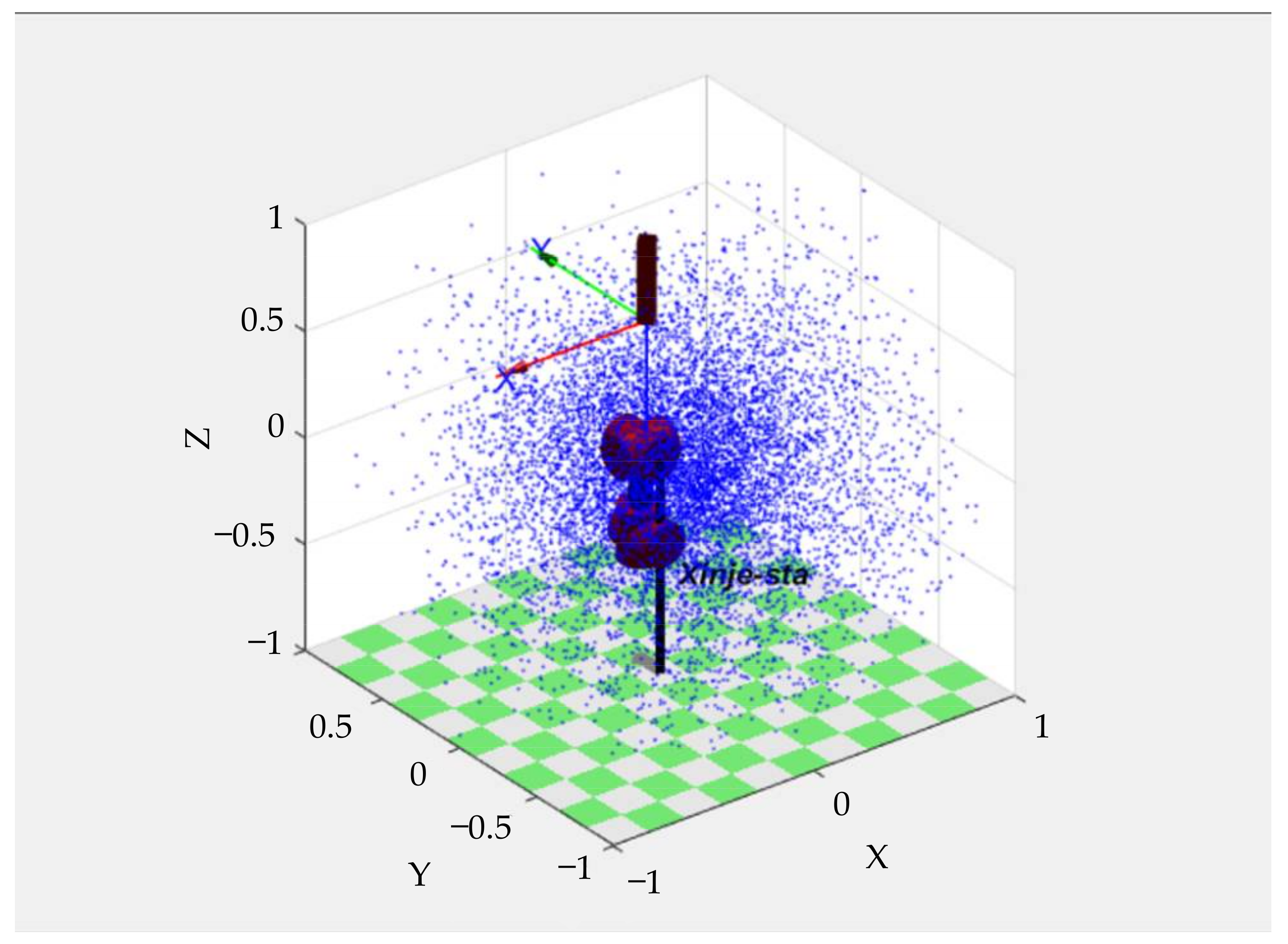
5. Experimental Verifications

5.1. Dimension Rapid-Exploration Random Tree Algorithm Effect Verification

This algorithm is based on the sampling principle of the RRT algorithm. According to the algorithm principle in this paper, this algorithm cannot complete the path search of points in a two-dimensional or three-dimensional space. Therefore, it only compares the advantages of various algorithms on the path planning effect of a four-dimensional manipulator.
A total of 120 groups of spatial random points are generated, covering all kinds of cross sector motion. The collision-free start and goal posture is calculated through inverse kinematics as the path start point and goal point. The path planning is carried out through the RRT* algorithm and the dimension-RRT algorithm, respectively. The optimization step number is 500, 1000, 1500, 2000, 2500, respectively. Since the start and goal points are spatial random points, the cost time, path length and other results do not have reference value. Here, the dimension data are processed taking RRT* results as the unit, and the average value of 120 groups of data is taken (Table 4).
This chart fully demonstrates the overall advantages of dimension-RRT over RRT*. Under the same amount of random points, the path quality of dimension-RRT is higher than of RRT*. With a gradual optimization, the optimization space decreases with the optimization process, and the ratio of dimension-RRT path length to RRT* path length increases. Compared with RRT*, the dimension-RRT algorithm has a higher optimization efficiency. Dimension-RRT can quickly obtain a relatively short path with fewer random points, which can be more intuitively shown in Figure 15.
However, due to the advance restriction of the first two DOFs in this algorithm, not all paths adopt the path with the smallest movement. Compared with the third and fourth DOFs, dimension-RRT will be overtaken by RRT* earlier in the length comparison of the first and second DOFs. As shown in Table 4, in the case of more optimization steps, the path length ratio of the first two DOFs is higher than that of the last two DOFs. So as far as the time consumption is concerned, the algorithm, taking the relationship between the path and obstacles in space into account, simplifies the path and estimates the time steps. The collision detection between the time steps is mostly omitted in the optimization process; therefore, the amount of calculation is greatly reduced and the planning efficiency is improved. Moreover, after the algorithm plans a stable trajectory and as there is no collision within the whole path network, the selection range of random points will be narrowed and the optimization efficiency will be further improved. However, in order to avoid a too large task space, a span of the two time steps in the task space before the stable trajectory appeared, which may lead to obstacles between the time steps. The algorithm will optimize the whole path network according to a predefined number of optimization steps to ensure the realization of the stable trajectory. This method will lead to unstable path planning time. In a few cases, the consumption time will be much greater than the average consumption time. This will be further discussed in Section 6.

5.2. Cross Sector Motion Planning

This algorithm can quickly obtain the path upon construction of building a perfect path library. In the planning process, first judge the cross sector motion type of the motion, and then screen the path with a closer distance in the cross sector motion path library as a reference for path planning.
It can be seen from Figure 16 that the path planned by this algorithm is relatively smooth. In the experiment, 50 groups of start and goal points are randomly generated for planning in the movement between the fourth pointing sector and the third posture sector. The average consumption time is 0.034 s. The path acquisition speed is faster than the RRT* and dimension-RRT algorithms, and can be applied to real-time path planning.

6. Discussion

As one of the main manipulator end effectors, the TPEE can effectively improve the manipulator working range. Current achievements in the manipulator research centered on the GEE, aiming to approach and contact the target position. The manipulator target with TPEE is different from the GEE since TPEE only needs the target point in its direction. Because of its different working objectives, the traditional path planning algorithms for the GEE will complicate the whole issue and ignore some of the necessary problems when applied to the TPEE. Designing the corresponding path planning strategy for the TPEE enabled the end effector to better complete the task. At present, studies on the wearable manipulator with the TPEE are limited, and most of them are passive manipulators. The current path planning method and kinematic modeling method of the wearable manipulator are not the optimal options for TPEE manipulator. This paper proposed a new DOF allocation scheme for a wearable TPEE manipulator as well as a corresponding path planning strategy which filled up this field blank. The division of the pointing sector and posture sector can effectively simplify the obstacle avoidance issue of path planning. The fake time dimension was also proposed to the path planning as the unified variable of multi DOFs. After decomposing the DOFs, the relationship between multiple groups of DOFs can be built through this unified variable. These above mentioned methods can also be applied to the simplification and solution of path planning of multiple DOF manipulators with various end effectors.

7. Conclusions

This paper proposed a DOF allocation method of wearable manipulators with TPEE and a path planning strategy for wearable manipulator with TPEE. Combined with the RRT algorithm principle, a path optimization algorithm dimension-RRT was also proposed. The optimized path result was referred for the manipulator in the form of a demo through the DMPS algorithm. The cross sector motion problem in this paper was mainly focused on the situation of target movement and target replacement, where the environment is a static one. However, as more complex situations are there in the actual situations, the wearable manipulators with TPEE should be more intelligent and more effective at solving the path planning problem in complex environments in the future. Detailed pointing sector and posture sector division is advisable to deal with the dynamic environment and non-ideal situations in latter studies. For the dimension-RRT algorithm, an addition of the fake time dimension to the algorithm should expand the potential to tackle the dynamic obstacle avoidance by constructing the mapping between time step and the spatial position of obstacles. Since there is no limitation on the path length between fake time steps in current path planning, the uncertainty of speed information would come up; then, the fake time in the obtained results should not be regarded as the real time or directly used for move planning. As for our follow-up work, the dimension-RRT algorithm will be applied to trajectory planning and dynamic obstacle avoidance by accurately dividing the fake time step and limiting the path length in the fake time step.

Author Contributions

K.Z., Z.L., H.L., X.G. (Xin’an Gao), M.Z., W.T. and X.G. (Xiaorong Guan) contributed to the design and implementation of the research, the analysis of the results, K.Z. contributed to the writing of the first draft of the manuscript. X.G. (Xiaorong Guan) and X.W. commented on previous versions of the manuscript. All authors have read and agreed to the published version of the manuscript.

Funding

This research was funded by National Defense Basic Scientific Research program of China, grant number JCKY2019209B003.

Informed Consent Statement

Informed consent was obtained from all subjects involved in the study.

Data Availability Statement

The python codes used and analyzed during the study are available from the first author on reasonable request.

Acknowledgments

Thanks to the experiment participants for their help and Nanjing University of Science and Technology for its support to this study.

Conflicts of Interest

The authors declare no conflict of interest.

References

  1. Xu, C.; Liu, Y.; Li, Z. Biomechtronic Design of a Supernumerary Robotic Limbs for Industrial Assembly. In Proceedings of the IEEE 4th International Conference on Advanced Robotics and Mechatronics (ICARM) IEEE, Toyonaka, Japan, 3–5 July 2019; pp. 553–558. [Google Scholar]
  2. Vatsal, V.; Hoffman, G. Design and Analysis of a Wearable Robotic Forearm. In Proceedings of the 2018 IEEE International Conference on Robotics and Automation (ICRA) IEEE, Brisbane, Australia, 21–25 May 2018; pp. 5489–5496. [Google Scholar]
  3. Kurek, D.A.; Asada, H.H. The MantisBot: Design and impedance control of supernumerary robotic limbs for near-ground work. In Proceedings of the IEEE International Conference on Robotics & Automation IEEE, Singapore, 29 May–3 June 2017; pp. 5942–5947. [Google Scholar]
  4. Véronneau, C.; Denis, J.; Lebel, L.P.; Denninger, M.; Blanchard, V.; Girard, A.; Plante, J.S. Multifunctional Remotely Actuated 3-DOF Supernumerary Robotic Arm Based on Magnetorheological Clutches and Hydrostatic Transmission Lines. IEEE Robot. Autom. Lett. 2020, 5, 2546–2553. [Google Scholar] [CrossRef]
  5. William, J.G.; Daniel, M.B.; Zachary, K.W.; Frank, M.; Angela, C.B. Third Arm Weapon Interface System. U.S. Patent No. US10393476B2, 20 December 2018. [Google Scholar]
  6. Wang, Y.P.; Jiang, Q. A Wearable Weapon Arm Device with Double Shooting Mode. CN112665462A, 16 April 2021. (In Chinese). [Google Scholar]
  7. Website: China National Knowledge Infrastructure. Available online: http://kns.cnki.net/kcms/detail/44.1240.TP.20210806.1351.028.html (accessed on 15 August 2021).
  8. LaValle, S.M.; Kuffner, J.J., Jr. Randomized kinodynamic planning. IJRR 2001, 20, 378–400. [Google Scholar] [CrossRef]
  9. Karaman, S.; Frazzoli, E. Sampling-based algorithms for optimal motion planning. IJRR 2011, 30, 846–894. [Google Scholar] [CrossRef]
  10. Burget, F.; Bennewitz, M.; Burgard, W. BI 2 RRT *: An efficient sampling-based path planning framework for task-constrained mobile manipulation. In Proceedings of the 2016 IEEE/RSJ International Conference on Intelligent Robots and Systems (IROS), Daejeon, Korea, 9–17 October 2016; pp. 3714–3721. [Google Scholar]
  11. Gammell, J.D.; Srinivasa, S.S.; Barfoot, T.D. Informed RRT *: Optimal sampling-based path planning focused via direct sampling of an admissible ellipsoidal heuristic. In Proceedings of the 2014 IEEE/RSJ International Conference on Intelligent Robots and Systems (IROS 2014), Chicago, IL, USA, 14–18 September 2014; pp. 2997–3004. [Google Scholar]
  12. Li, B.H.; Chen, B.D. An Adaptive Rapidly-Exploring Random Tree. IEEE/CAA J. Autom. Sin. 2022, 9, 283–294. [Google Scholar] [CrossRef]
  13. Ganesan, S.; Natarajan, S.K.; Srinivasan, J. A Global Path Planning Algorithm for Mobile Robot in Cluttered Environments with an Improved Initial Cost Solution and Convergence Rate. Arab. J. Sci. Eng. 2022, 47, 3633–3647. [Google Scholar] [CrossRef]
  14. Guo, Y.C.; Liu, X.X.; Liu, X.H.; Yang, Y.; Zhang, W.G. FC-RRT *: An Improved Path Planning Algorithm for UAV in 3D Complex Environment. Int. J. Geo-Inf. 2022, 11, 112. [Google Scholar] [CrossRef]
  15. Wang, H.; Li, G.Q.; Hou, J.; Chen, L.Y.; Hu, N.L. A Path Planning Method for Underground Intelligent Vehicles Based on an Improved RRT * Algorithm. Electronics 2022, 11, 294. [Google Scholar] [CrossRef]
  16. Zang, X.Z.; Yu, W.T.; Zhang, L.; Iqbal, S. Path Planning Based on Bi-RRT Algorithm for Redundant Manipulator. In Proceedings of the International Conference of Electrical, Automation and Mechanical Engineering (EAME 2015), Phuket, Thailand, 26–27 July 2015; pp. 189–191. [Google Scholar]
  17. Khan, A.T.; Li, S.; Kadry, S.; Nam, Y. Control Framework for Trajectory Planning of Soft Manipulator Using Optimized RRT Algorithm. IEEE Access 2020, 8, 171730–171743. [Google Scholar] [CrossRef]
  18. Yang, W.; Wen, H.Y.; Zhang, Z.S. Obstacle Avoidance Path Planning of Manipulator Based on Improved RRT Algorithm. In Proceedings of the 2021 International Conference on Computer, Control and Robotics (ICCCR), Shanghai, China, 8–10 January 2021; pp. 104–109. [Google Scholar]
  19. Wei, H.H.; Zheng, Y.; Gu, G.Y. RRT-Based Path Planning for Follow-the-Leader Motion of Hyper-Redundant Manipulators. In Proceedings of the 2021 IEEE/RSJ International Conference on Intelligent Robots and Systems (IROS), Prague, Czech Republic, 27 September–1 October 2021; pp. 3198–3204. [Google Scholar]
  20. Shao, J.; Xiong, H.; Liao, J.F.; Song, W.; Chen, Z.; Gu, J.; Zhu, S.Q. RRT-GoalBias and Path Smoothing Based Motion Planning of Mobile Manipulators with Obstacle Avoidance. In Proceedings of the 2021 IEEE International Conference on Real-time Computing and Robotics, Xining, China, 15–19 July 2019; pp. 217–222. [Google Scholar]
  21. Yi, J.; Yuan, Q.; Run, S.; Bai, H. Path Planning of a Manipulator Based on an Improved P_RRT* Algorithm. Complex Intell. Syst. 2022. Available online: https://doi.org/10.1007/s40747-021-00628-y (accessed on 18 April 2022).
  22. Wang, Y.F.; Gui, Z.C.; He, J.; Zhang, X.W.; Wang, C.S. Autonomous Intelligent Mine Clearance and Explosive Distributing Mechanical System. CN107246824A, 13 October 2017. (In Chinese). [Google Scholar]
  23. Wang, Q.F.; Liu, M.Y.; Liu, J.D. Dual-arm Robot Mine Clearance Cooperative Control System and Mine Clearance Method. CN109807913A, 28 May 2019. (In Chinese). [Google Scholar]
  24. Ding, H.G. Intelligent Demining Robot. CN109696085A, 30 April 2019. (In Chinese). [Google Scholar]
  25. Wang, C. Study on the Design of Remote Control Weapon Station Structure; National University of Defense Technology: Changsha, China, 2018. [Google Scholar]
  26. Wu, D.; Gu, Z.C.; Wang, Y.J.; Xu, C. Electromechanical Joint Simulation of a Small Unmanned Combat Platform. J. Ordnance Equip. Eng. 2020, 41, 92–96. [Google Scholar]
  27. Zhu, Z.Y.; Yang, Z.G.; Wang, J.B.; Zhang, Q.; Fan, X.J.; Wu, W. Machine Gun Remote Control Weapon Station. CN207716963U, 10 August 2018. (In Chinese). [Google Scholar]
  28. Chang, T. Automatic Defense Weapon Station. CN111486751A, 4 August 2020. (In Chinese). [Google Scholar]
  29. Qiu, S.P.; Chen, B. An Unmanned Weapon Station. CN211668356U, 25 September 2019. (In Chinese). [Google Scholar]
  30. Berenson, D.; Srinivasa, S.; Kuffner, J. Task Space Regions: A Framework for Pose-Constrained Manipulation Planning. Int. J. Robot. Res. 2011, 30, 1435–1460. [Google Scholar] [CrossRef]
  31. Kim, J.; Ko, I.; Park, F.C. Randomized Path Planning on Foliated Configuration Spaces. In Proceedings of the 11th International Conference on Ubiquitous Robots and Ambient Intelligence (URAI 2014), Kuala Lumpur, Malaysia, 12–15 November 2014; pp. 209–214. [Google Scholar]
  32. Chen, Z.; Ma, L.; Shao, Z. Path Planning for Obstacle Avoidance of Manipulators Based on Improved Artificial Potential Field. In Proceedings of the Chinese Automation Congress (CAC), Hangzhou, China, 22–24 November 2019; pp. 2991–2996. [Google Scholar]
  33. Henten, E.; Hemming, J.; Tuijl, B.; Kornet, J.G.; Bontsema, J. Collision-free Motion Planning for a Cucumber Picking Robot. Biosyst. Eng. 2003, 86, 135–144. [Google Scholar] [CrossRef]
  34. Islam, F.; Nasir, J.; Malik, U.; Ayaz, Y.; Osman, H. RRT *-Smart: Rapid convergence implementation of RRT * towards optimal solution. In Proceedings of the 2012 IEEE International Conference on Mechatronics and Automation, Chengdu, China, 5–8 August 2012; pp. 1651–1656. [Google Scholar]
  35. Huang, Y.; Abu-Dakka, F.J.; Silvério, J.; Caldwell, D.G. Generalized Orientation Learning in Robot Task Space. In Proceedings of the 2019 International Conference on Robotics and Automation (ICRA), Montréal, QC, Canada, 20–24 May 2019; pp. 2531–2537. [Google Scholar]
  36. Muelling, K.; Kober, J.; Peters, J. Learning Table Tennis with a Mixture of Motor Primitives. In Proceedings of the 2010 IEEE-RAS International Conference on Humanoid Robots, Nashville, TN, USA, 6–8 December 2010; pp. 411–416. [Google Scholar]
  37. Shyam, R.A.; Zhou, H.; Montanaro, U.; Neumann, G. Imitation Learning for Autonomous Trajectory Learning of Robot Arms in Space. arXiv preprint 2020, arXiv:2008.04007. [Google Scholar]
  38. Schaal, S. Dynamic Movement Primitives—A Framework for Motor Control in Humans and Humanoid Robotics. In Adaptive Motion of Animals and Machines; Springer: Berlin/Heidelberg, Germany, 2006. [Google Scholar]
  39. Huang, Y.L.; Xu, D.; Tan, M. On imitation learning of robot movement trajectories: A survey. Acta Autom. Sin. 2022, 48, 315–334. [Google Scholar]
  40. Mei, Z.; Chen, Y.; Zhang, S.L.; Zheng, X.J.; Wu, H.Y. Mobile Robot Path Planning Based on Continuous Dynamic Movement Primitives. Inf. Control 2019, 48, 12–20. [Google Scholar]
Figure 1. Structural forms of some manipulators with GEEs.
Electronics 11 01615 g001
Figure 2. DOF assignment scheme for end effectors. (a) with a cylinder blind area; (b) with a cone blind area.
Electronics 11 01615 g002
Figure 3. Wearable manipulators with TPEE DOF allocation scheme.
Electronics 11 01615 g003
Figure 4. Feasible manipulator workspace solved by the Monte Carlo method.
Electronics 11 01615 g004
Figure 5. World coordinate system (Wxyz) and pointing system coordinate system (Sxyz).
Electronics 11 01615 g005
Figure 6. Schematic diagram of the third degree of freedom calculation process.
Electronics 11 01615 g006
Figure 7. Schematic diagram of the fourth degree of freedom calculation process.
Electronics 11 01615 g007
Figure 8. Posture sectors division.
Electronics 11 01615 g008
Figure 9. Pointing sector division.
Electronics 11 01615 g009
Figure 10. Flow chart of path planning strategy.
Electronics 11 01615 g010
Figure 11. Path planning algorithm results schematic diagram.
Electronics 11 01615 g011
Figure 12. Schematic diagram of posture network.
Electronics 11 01615 g012
Figure 13. Start and end point set of random cross sector motion (red as the starting point and blue as the ending point).
Electronics 11 01615 g013
Figure 14. Effect after path adjustment.
Electronics 11 01615 g014
Figure 15. Path length by Prandoms numbers.
Electronics 11 01615 g015
Figure 16. The effect of path adjustment.
Electronics 11 01615 g016
Table 1. Correspondence between the first and second DOFs in posture sector.
Posture SectorDOF1DOF2
1−50160
250160
3−5020
45020
Table 2. Pointing sector division judgment criteria.
Pointing SectorJudgment Criteria
1x ≥ 0 and y < x ∗ tan(30°);
x < 0 and z > x ∗ tan(200°) and y < x ∗ tan(160°)
2x < 0 and z > x ∗ tan(200°) and y > x ∗ tan(200°);
x ≥ 0 and y > x ∗ tan(−30°)
3y < x ∗ tan(160°) and x < 0 and z < x ∗ tan(160°);
x ≥ 0 and y < x ∗ tan(30°)
4x < 0 and z < x ∗ tan(160°) and y > x ∗ tan(200°);
x ≥ 0 and y > x ∗ tan(−30°)
Table 3. DOF1, DOF2 path data between different posture sectors.
Start Posture SectorTarget Posture Sector(DOF1, DOF2) Path Data
12[−50, 160], [−30, 150], [−15, 140], [0, 140], [15, 140], [30, 150], [50, 160]
13[−50, 160], [−50, 136], [−50, 113], [−50, 90], [−50, 67], [−50, 44], [−50, 20]
14[−50, 160], [−40, 136], [−20, 113], [0, 90], [20, 67], [40, 44], [20, 50]
21[50, 160], [30, 150], [15, 140], [0, 140], [−15, 140], [−30, 150], [−50, 160]
23[50, 160], [40, 136], [20, 113], [0, 90], [−20, 67], [−40, 44], [−50, 20]
24[50, 160], [50, 136], [50, 113], [50, 90], [50, 67], [50, 44], [50, 20]
31[−50, 20], [−50, 44], [−50, 67], [−50, 90], [−50, 113], [−50, 136], [−50, 160]
32[−50, 20], [−40, 44], [−20, 67], [0, 90], [20, 113], [40, 136], [50, 160]
34[−50, 20], [−40, 30], [−20, 40], [0, 40], [20, 40], [40, 30], [50, 20]
41[50, 20], [40, 44], [20, 67], [0, 90], [−20, 113], [−40, 136], [−50, 160]
42[50, 20], [50, 44], [50, 67], [50, 90], [50, 113], [50, 136], [50, 160]
43[50, 20], [40, 30], [20, 40], [0, 40], [−20, 40], [−40, 30], [−50, 20]
Table 4. Experimental results.
Random Points Number in OptimizationTime Consuming ComparisonPath Length ComparisonPath Length Comparison of the Second DOF GroupPath Length Comparison of the First DOF Group
5000.5230.5000.4090.582
10000.4920.5660.4640.651
15000.4620.6360.5310.714
20000.4010.6660.5650.737
25000.3770.6840.5850.745
Publisher’s Note: MDPI stays neutral with regard to jurisdictional claims in published maps and institutional affiliations.

