Article

An IoT System for Real-Time Monitoring of DC Motor Overload

Faculty of Electrical Engineering, University of Montenegro, 81000 Podgorica, Montenegro
*
Author to whom correspondence should be addressed.
Electronics 2022, 11(10), 1555; https://doi.org/10.3390/electronics11101555
Submission received: 24 March 2022 / Revised: 2 May 2022 / Accepted: 11 May 2022 / Published: 12 May 2022

Abstract

:
The excavators are heavy machines widely used in the civil engineering and surface mining industry. Recent studies show that 95% of contractors face the problem of finding skilled operators. Unskilled operators not only worsen productivity but also very often cause machine failures through unprofessional handling. Motivated by these studies and guided by the mining company’s requirements, we present a prototype of an IoT system for monitoring DC motor overload on the EKG-15 excavator. The IoT system consists of a microprocessor device mounted inside the excavator and an external cloud platform that can be accessed via the Internet. The proposed solution detects and warns the operator when the DC motor overload occurs, thus reducing the probability of its damage. In addition, overload data is sent to the cloud platform for later research, analysis and processing. The main benefit of the proposed solution is that it can be applied to existing industry machinery, thus reducing the maintenance cost and increasing productivity. After several months of use of the proposed system in real working conditions, it has been shown that the overload occurrence and its duration time are approximately reduced by 60% and 80%, respectively.

1. Introduction

Industrial developments in recent decades have largely depended on the design, development and implementation of various industrial machines and plants. Consecutively, the rapid development of industry has also accelerated comprehensive progress in the efficiency of industrial machines. Productivity in a specific industrial activity largely depends on the efficiency of these machines, as well as on the training of machine operators [1]. Therefore, to achieve optimal results, it is not only important to have modern, efficient, accurate, and robust industrial machines but also a skilled workforce [2]. Any possible malfunction or irregularity that makes the machine inefficient or even unusable (for a longer or shorter time) leads to production losses and, in some cases, disruptions. Machines that have moving wear parts or elements, which are in frequent contact with abrasive or hard materials, are particularly exposed to this problem.
Excavators are one of the most heavily used equipment in the construction and mining industries, typically sold for hundreds of thousands of dollars per machine [3]. Excavator operation is a quite complex process that requires skilled and experienced operators. Recently, the lack of skilled labor has been reported worldwide in both developed and developing countries. Ninety-five percent of contractors in the United States have stated that they have difficulty finding the skilled workers [4]. Similar shortages have been reported in Hong Kong [5], European countries [6], New Zealand [7], etc. The same problem faces “Rudnik Uglja Pljevlja” (RUP), the coal mining company in Montenegro [8]. RUP has persistent and significant maintenance costs for these excavators caused by overloading or improper operator handling. In addition to the cost of repairing the excavator, there are also reductions in production due to the excavator’s downtime.
The labor shortage and demands for increased productivity have accelerated the research on the automation of the excavation process. Different control algorithms for automation and/or optimizing the right time for switching from the drag to the scoop phase of the bucket can be found in the literature [9,10,11]. Some studies deal with the identification of soil parameters, which can be further used to predict the forces acting on the bucket and improve the excavation strategy by avoiding overloading that could damage the machine [12,13]. Sometimes, it is hard to predict soil interaction forces, so some researchers propose the control approach for autonomous excavation independent of the soil composition [14]. Humans still more efficiently execute many processes than machines, so some researchers have focused on a hybrid approach, where inputs from the controller and a human are continuously combined to perform a specific task [15]. Similarly, the control system that assists a novice operator in the operation of excavation work is proposed in [16].
It is well known that robotics and automatized systems have revolutionized many industry sectors, but their adoption in the construction and mining industry is still limited and slow [17]. Even though many sophisticated control/optimization algorithms have been proposed in the literature to automate the excavation process, most of them have not yet been put into practice [18]. One of the main reasons is that there is a gap between industry and academia, and it takes a long time for the solutions proposed in the literature to be applied and accepted in the industry [17]. On the other hand, in some specific areas of application, such as the mining industry, full automation of the excavation process is sometimes challenging or even impossible, due to the complex terrain configuration and soil type [19,20]. Automation is further complicated by the fact that the types and forms of earthworks are inconsistent, and work plans sometimes change depending on working conditions. In [21] authors conclude that the subject demands more research, together with industrial support, to speed up the process toward successful autonomous excavators.
High cost of implementation, financial risks, and inadequate cost–benefit analysis are other factors that slow down the adoption of robotics in the mining industry [22]. Replacing conventional industrial machines with robotic machines is often not acceptable and can affect the survival of companies. Therefore, the solution needs to be sought in the other modern technological developments such as the IoT paradigm, sensing technologies, etc. [23]. IoT has proven to be a successful and widely accepted technology because it can increase the productivity and quality of existing industrial systems and machines with reasonable investments [24,25,26]. When designing new IoT solutions, it is desirable to establish tight cooperation between the academy and industry, i.e., it is necessary to (a) systematically investigate industry-specific challenges, (b) understand stakeholders’ expectations, and (c) establish functional and cost requirements.
In this paper, we consider the problem of frequent failure of DC motors in EKG-15 excavators. Every year, the RUP has considerable maintenance costs for these excavators, caused by overloading or improper operator handling [27]. This paper presents the IoT system for monitoring of DC motor overload, with the following features: (i) has a simple and low-cost implementation; (ii) does not affect the existing excavator’s control system; (iii) warns the operator when overload is detected; (iv) can be integrated with existing cloud platforms; (v) collects overload data and sends it to the cloud for further analysis and processing. To the best knowledge of the authors, there is no available solution to this problem in the literature.
The development of the IoT system is conducted through several phases. In the first phase, the problem of excavator overload is analyzed, and functional requirements are defined in cooperation with the RUP company. In the second phase, the architecture of the IoT system that meets the functional requirements is designed. The implementation of the IoT system is carried out in the third phase. In the final phase, the system is tested, and the results are analyzed. Based on the obtained results, some future improvements to the IoT system are proposed. All mentioned phases are depicted in Figure 1.
The paper is organized as follows. The analysis of the problem and motivation behind the proposed approach are described in Section 2. The Section 3 presents the architecture of the proposed solution. The circuit for detecting the overload of DC motors is described in detail, as well as the realization of communication between the microcontroller and the appropriate cloud platform. Section 4 presents a prototype of the installed device and the experimental results obtained during the operation of the proposed system in real conditions. Finally, the discussion and concluding remarks are given.

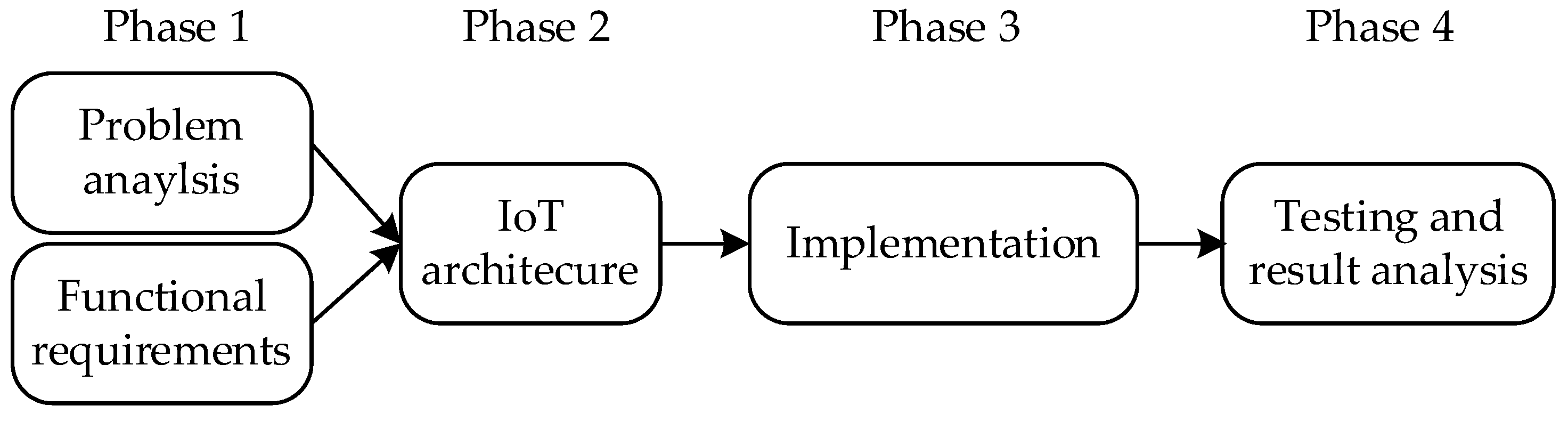
2. Analysis of the Problem

2.1. The Case Study of the EKG-15 Excavator

In this paper, we consider the EKG-15 model of the excavator, which is used for work on the surface mine within the RUP company. The EKG-15 is a robust conventional excavator with a loading bucket controlled by high-power DC motors. Although these motors are designed to ensure the long life of the excavator, they can become overloaded if the loading bucket gets stuck due to extremely hard terrain. Namely, if the operator does not release the lever that controls the movement of the loading bucket, the motor will still try to move the bucket. In those moments, a so-called short circuit occurs, i.e., a large quantity of current passes through the motor. If the operator does not react quickly and releases the lever, the short-circuit current threatens to damage the motor. If this happens, the motor and thus the excavator will be out of use, which reduces productivity. The repair of these motors is quite expensive and cannot be performed in a short time.
On excavators used by RUP, the short-circuit current is limited by the manufacturer to the value of 2 kA as a preventive measure. This means that the current flowing through the motor windings will not exceed this value. However, there is no protection provided regarding the duration of the short-circuit condition. In other words, a current of 2 kA will flow through the motor windings as long as the operator activates the bucket control lever. If the operator keeps the motor active for a long time, the conductor will heat up and the motor will burn out. Operators can unintentionally cause a condition that leads to a short-circuit current in the motors and often do not recognize in time that such a situation has occurred. This inevitably leads to motor breakdown.
A system for monitoring the current flow through the DC motor windings has already been implemented in the EKG-15 excavator by using a small (shunt) resistor. The voltage from the shunt is brought to an analog voltmeter, calibrated in (kilo) amperes since the strength of the current flowing through the motor is an important issue. This instrument has a symmetric scale, since the current can flow in both directions. One such voltmeter is in the operator’s cabin of the excavator, so that operator can continuously follow the indication of the motor load. The fact that the operator needs to continuously monitor the DC current indicator while navigating the mine surface significantly raises safety concerns and reduces work efficiency. Therefore, it would be better to warn the operator in some way when the motor is overloaded.

2.2. Functional Requirements

According to the contract between the RUP and the excavator supplier, the control architecture, principles, or devices within the excavator must not be changed or modified. Therefore, the only acceptable solution for RUP is to design a system that will assist the operator and help the RUP maintenance team without interfering with the excavator or affecting any part of it. To the best knowledge of the authors and the RUP maintenance team, there is no solution for this problem in the available literature.
The system to be designed should be able to detect a short-circuit current occurrence and in a reliable way warn the operator that the undesirable situation has occurred. In this way, the operator could act preventively and stop the motor activity before damage occurs. This will prevent frequent and long-lasting short-circuit current, thus extending motor life. In addition, it is necessary to record and send to the external server information related to the occurrence of short-circuit current. More specifically, it is necessary to know how many times and for how long the motor was overloaded. Based on this information, the operator’s incorrect handling can be determined, and possible errors can be pointed out during the next training. This data can be also used to analyze the cause of potential motor burnout, and for further research and development.
All technical requirements for the system design are summarized in Table 1.

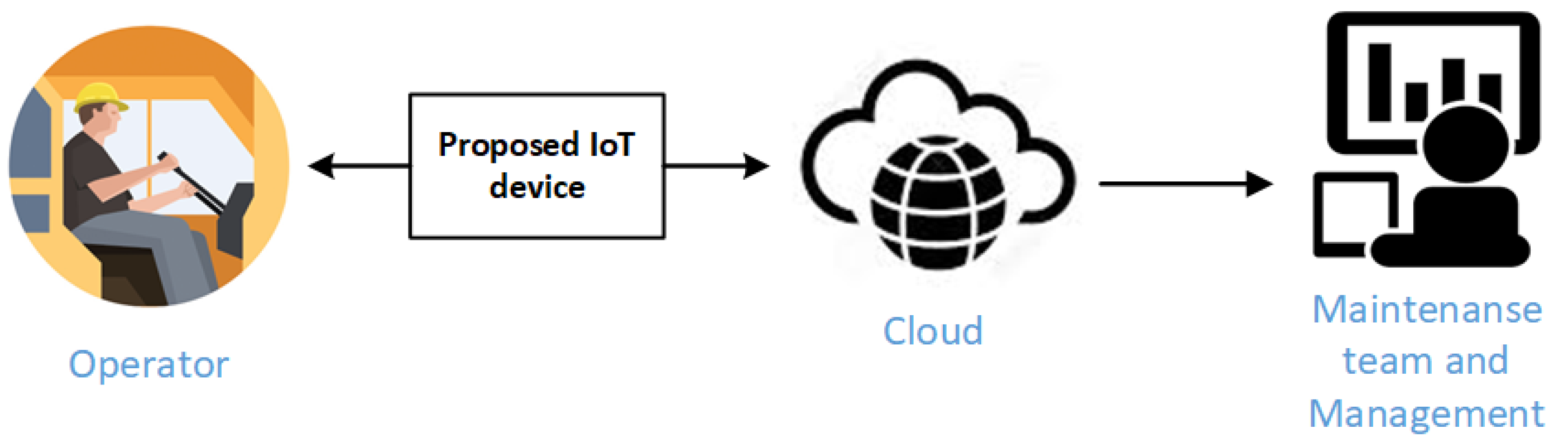
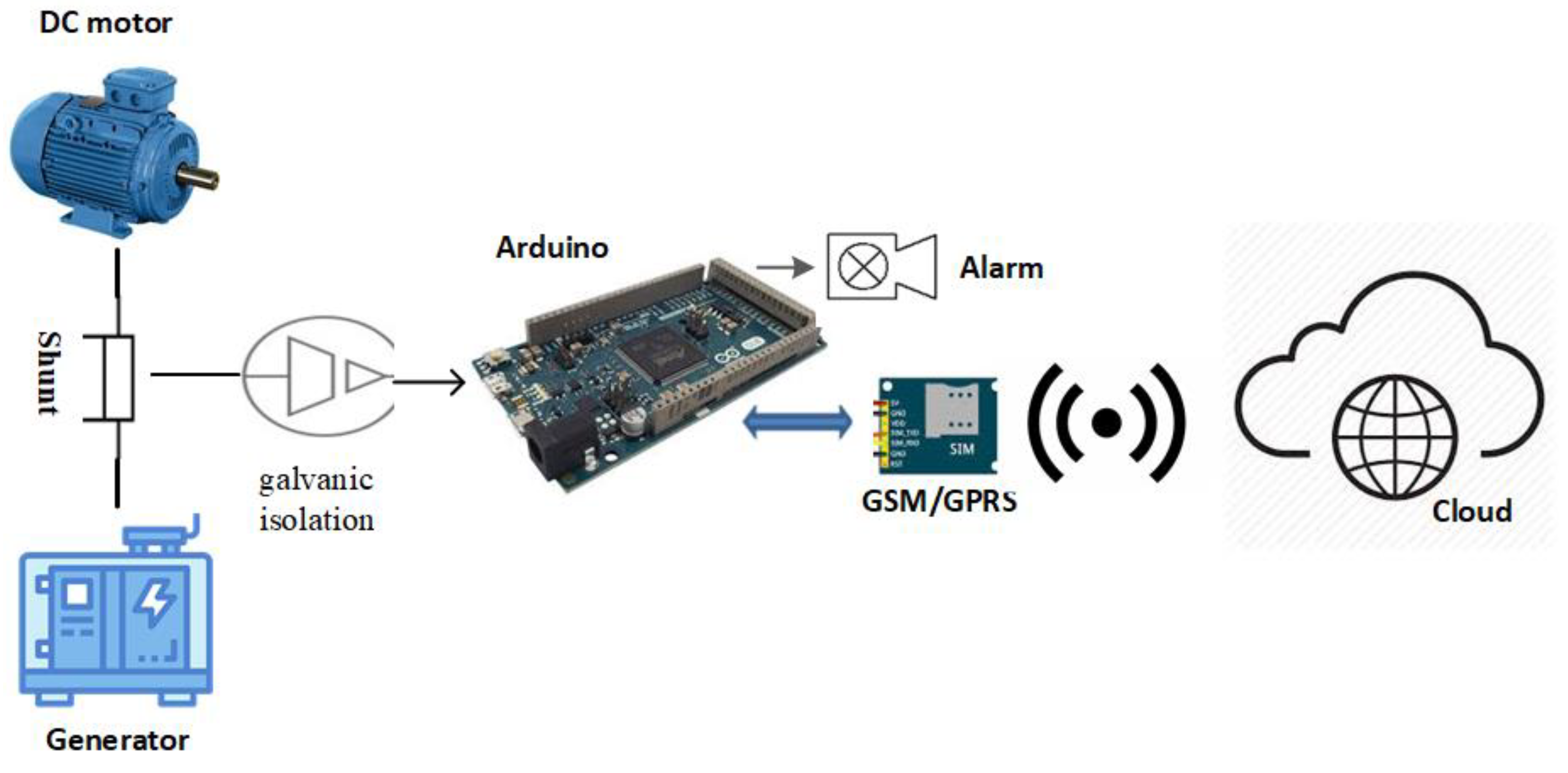
3. Architecture of the Proposed Solution

The architecture of the system that complies with the technical requirements given in Table 1 is conceptually illustrated in Figure 2. The proposed IoT device is based on the widely known Arduino open hardware platform [28,29]. When the device detects a short-circuit, it warns the operator with an audio signal. Furthermore, the data that is permanently stored on the cloud is analyzed and visualized, providing the maintenance team with adequate monitoring capability to perform fast intervention and preventive maintenance in case of motor overloads. Finally, analysis of large amounts of data from multiple excavators will help company management to improve operators’ skills, work processes, energy efficiency while reducing cost.
Any standardized IoT cloud platform can be used for this purpose, but we used the open UoM IoT platform [30]. It is a free and open platform developed at the University of Montenegro, Faculty of Electrical Engineering, within the NI4OS project [31]. In addition to providing free data storage, this service offers visualization of the stored data.

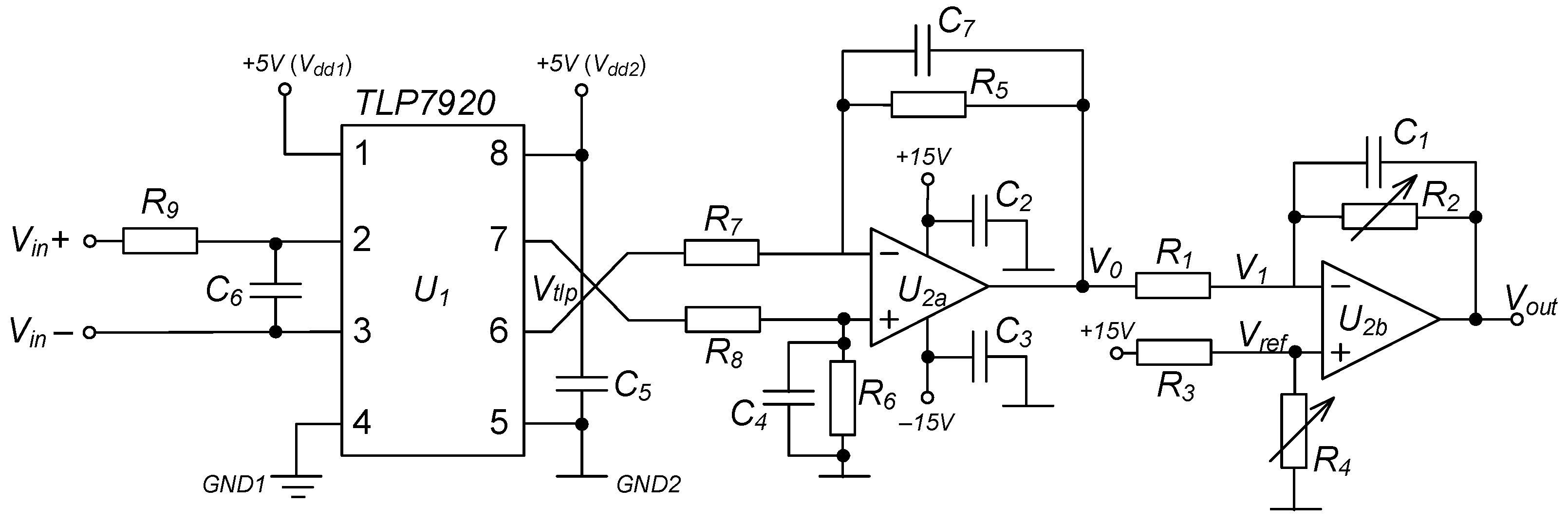
3.1. Short-Circuit Detection of Excavator’s DC Motor

The principal scheme of the short-circuit detection system is depicted in Figure 3. A solution was adopted that does not cut off the short-circuit current through the motor, which left the control electronics system unchanged. Instead, a strong siren (alarm) will generate the warning signal to the operator when a critical event occurs. It will serve not only as a warning, but also as an incentive for the operator to stop the overcurrent motor mode. The sound intensity and frequency have been chosen to be an inconvenience to the operator when exposed, even for a short time. Since this siren is supplied with electricity taken from the power supply unit of the excavator, its activation is performed utilizing a common relay.
Monitoring the voltage on the shunt in the motor circuit is the most important and the most critical element of the designed system. Since Arduino is chosen as the platform for our solution, voltage monitoring is performed using a built-in A/D converter. Inside each excavator, it is necessary to monitor two DC motors. In the first version of the proposed system [27], the microcontroller monitored each motor individually by the voltage on the shunts in front of these motors. However, the same generator powers both motors, so it is imperative that the generator current does not exceed a critical value. Therefore, in the final version of the system, the microcontroller monitors the voltage on the shunt in the generator circuit. That makes the system simpler and easier to implement (Figure 3).
The motor short-circuits current detection system continuously monitors the voltage from the abovementioned shunt. When overload occurs, a short-circuit current of 2 kA generates a voltage of about 75 mV on this resistor. As long as the current through the motor (consequently the voltage on the shunt) is below some critical value, the system does not take any particular action. This critical value of the voltage to which the system reacts is set to 65 mV. When the voltage over the critical value is detected, the system starts to measure the duration of the overload event. According to the manufacturer, 2 kA current is not harmful to the motor if it lasts less than 9 s. For this reason, the system alarms the operator and starts data recording when the duration exceeds 3 s.
The voltage on the monitored shunt changes its polarity as the motor changes direction of rotation. This is a challenge for the acquisition process because DC voltage powers the microcontroller, as well as its A/D converter. Therefore, the A/D converter cannot measure the voltage that is “negative” from the point of view of the microcontroller. On the other hand, it is mandatorily for the monitoring system to be galvanically isolated from the monitored circuit. This means that it is not possible to apply voltage from the shunt directly to the input of the microcontroller A/D converter.
To circumvent this issue, we have designed a module that adjusts the voltage generated on the shunt to the requirements of the A/D converter on the Arduino (Figure 4). The first task of this module is to perform galvanic isolation between the voltage on the shunt and microcontroller circuit. This has been achieved by a TLP7920 optically isolated amplifier from Toshiba Corporation [32]. Voltage from the shunt (Vin in Figure 4) is brought to the input of TLP7920. At the outputs of this amplifier (between pins 6 and 7 - Vtlp in Figure 4), there is a voltage proportional to the voltage on the shunt, but galvanically isolated. An experimentally determined dependence between the input and output voltage is shown in Table 2. The input voltage for this measurement was generated using a PeakTech 6225 A power supply and supplied to the Vin input via a voltage divider. The ratio on the voltage divider is 1:100, so the voltage from the power supply varies from 0 V to 8 V. Of course, negative voltages are generated by rotating the power supply terminals. The output voltage was measured using a Mastech MS8221C multimeter. Since this project does not require very high accuracy of the measured voltage, these instruments are fully suitable for this job.
The voltage at the output of TLP7920 is differential voltage in a small range, which needs to be reshaped before further analysis. This is performed by an operational amplifier labeled by U2a in Figure 4. Resistors R5–R8 are chosen so that the voltage difference at the outputs of the TLP7920 (Vtlp) is multiplied by 5. This means that the voltage at the output of the operational amplifier U2a ranges from −3 V to 3 V. This voltage is related to the voltage that powers the microcontroller, but it also has negative values from the point of view of the microcontroller. It means that cannot be read by the microcontroller’s A/D converter. In addition, the range of 6 V is too large for this converter. Therefore, this voltage needs to be further adjusted by translating its range to a single polarity range before it is fed to the converter in the microcontroller. In addition, it should be adjusted to utilize the entire input range of the A/D converter and thus get a more accurate reading. Both tasks are performed by an operational amplifier labeled by U2b in Figure 4.
The voltage at the output of the operational amplifier U2b can be calculated according to the following formula:
V o u t = V r e f + V r e f V 0 R 1 · R 2
The A/D converter of the used Arduino platform accepts input voltage in the range from 0 V to 3.3 V. Since the output voltage of the operational amplifier U2a (V0) ranges from −3 V to 3 V, variable resistor R2 and reference voltage Vref are calculated to satisfy two following conditions:
I f   V 0 = 3   V   t h e n   V o u t = 0   V
I f   V 0 = 3   V   t h e n   V o u t = 3   V
The resistance of resistor R1 is set to 10 KΩ. Therefore, from (1)–(3) a system of two equations with two variables is obtained:
{ 0 = V r e f + V r e f     3 10   K · R 2 3 = V r e f + V r e f   +   3 10   K · R 2
By solving (4), we get Vref = 1 V and R2 = 5 KΩ. The value of Vref is adjusted via the voltage divider implemented by resistors R3 and R4. In order to be able to fine-tune the desired values, potentiometers are used instead of fixed value resistors.
In the manner described above, in addition to the galvanic separation of the shunt voltage from the microcontroller part, we achieve shunt voltage adjustments to the input range of the A/D converter on the Arduino platform. An experimentally determined dependence between the input and output voltage of the circuit shown in Figure 4 is presented in Table 3. These results show that the output voltage is immune to exceeding its range of 0–3 V for input voltages that sometimes slightly exceed the recommended thresholds. We assumed that the extreme input voltage values are ±80 mV while the actual values are ±75 mV. Given that the A/D converter accepts inputs between 0 and 3.3 V, the circuit has the potential for future upgrades/modifications.
During the experiment, we found that when the inputs are not connected, the voltage at the output could be outside of the range acceptable to the microcontroller. To protect the microcontroller from damage, the inputs of the circuit are connected with a 1 MΩ resistor. Due to the very low resistance of the shunt, the inserted resistor does not interfere with regular system operation.
The value of Vout must be read continuously to reliably detect motor overload periods. However, in addition to reading the value of the voltage applied to the input of the A/D converter, the microcontroller must perform several other tasks. For example, writing to the LCD, reading from the Real-Time Clock (RTC), sending data to the cloud, and so on. Therefore, we decided to perform a reading of the A/D converter within the interrupt service routine (ISR). The ISR period is set to 100 ms, so each action related to the reading of shunt voltage is set to the multiple of that period.
If the voltage on the shunt remains above the critical limit for more than 3 s, the measuring of the overload duration begins. At the same time, a siren activates and warns the operator that the motor is overloaded. During each ISR execution, if the voltage is still above the limit, a counter used to calculate the overload duration is incremented. The overload duration is obtained as the product of the counter value and the measurement interval of 100 ms. This calculated duration is recorded on the SD memory card when the voltage returns to a value below the alarm limit. An adapter PmodSD manufactured by Digilent is used to access the memory card [33].
Repeated occurrence of short-circuit current that lasts close to 3 s (less than a threshold), followed by the short-term return of the current intensity to the allowed range, is possible in rare occasions. While, strictly speaking, these events do not represent a longer than 3 s overload, they may still cause motor damage. For that reason, the counter of the implemented system is not reset when the current level goes below the critical threshold. Instead, it is decremented and will only reach zero if the short circuit does not repeat in quick succession. Otherwise, the repeated event(s) will be detected as a 3-second overload. In this way, the above-mentioned scenario is considered, which mitigates the risk of the motor damage. However, for simplicity, we will treat these events as continuous 3 s events in the subsequent text.
In order to perform the successful analysis of motor overload cases, we must also know the exact time of critical events. Based on the overload duration and the time in which it happened, conclusions about the work of individual operators can be drawn, as well as the mode in which the excavator’s motors worked. The easiest way to deal with the exact time is to use the Real-Time Clock (RTC) circuit. We used the DS3231 RTC chip in our design. The date and time are loaded from the RTC chip each time the motor is overloaded for more than the critical duration. Then, the system creates a file named by the date just read from RTC, if that file does not already exist. This intuitive file naming convention simplified the process of pinpointing the occurrence of critical events in a day to just looking up the file created on the desired date (with the date as its name). In this file, the overload duration and the exact time of the overload occurrence are recorded.

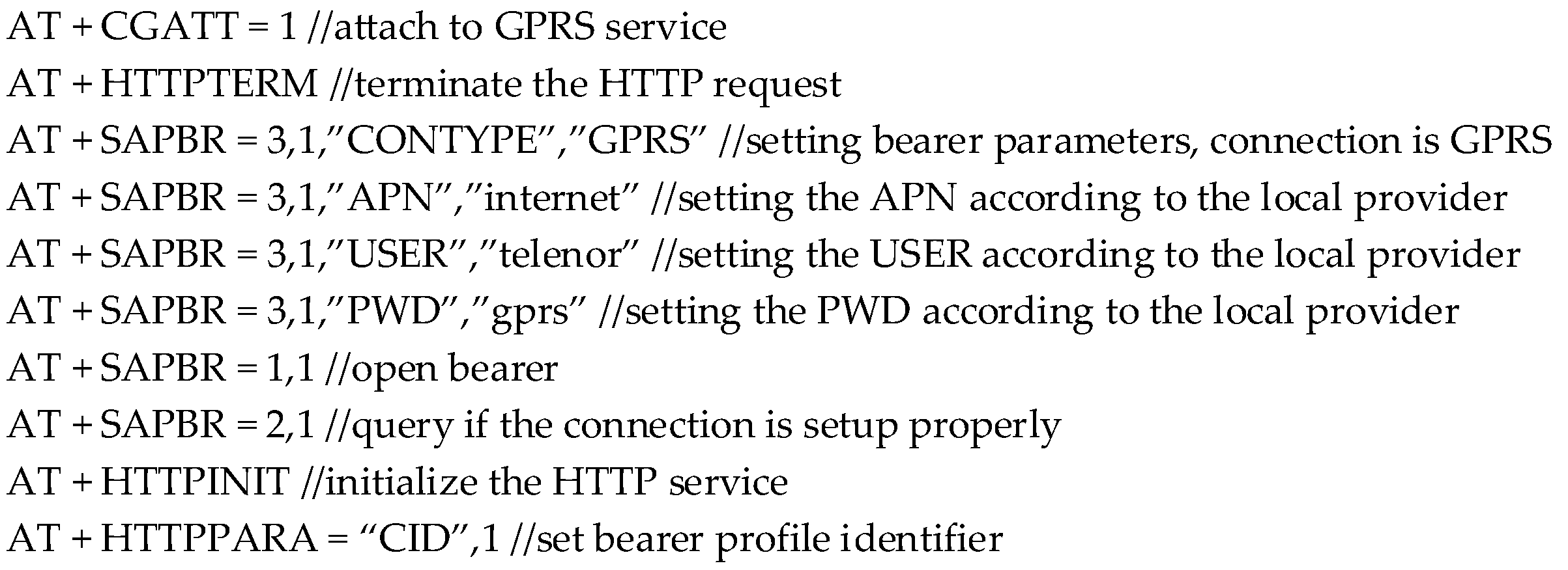
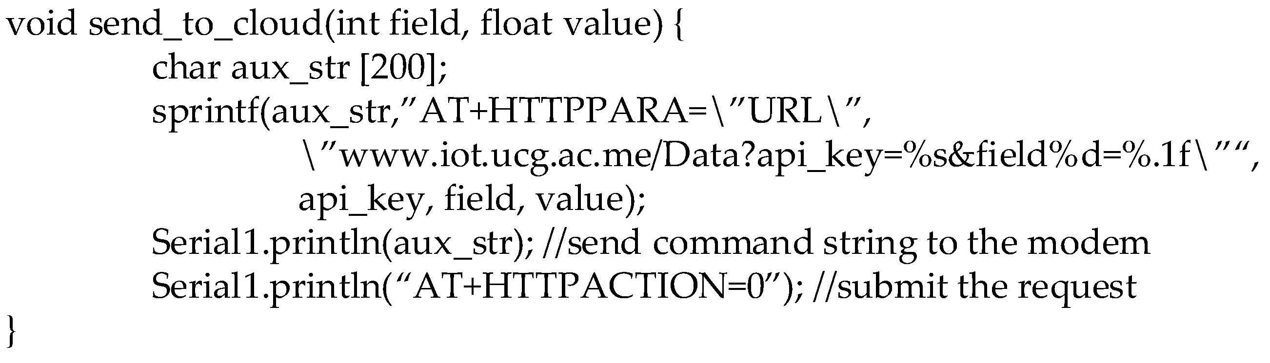
3.2. Communication between IoT Device and the Cloud

Information about the duration of motor overload together with the time stamp, need to be transferred to the cloud, immediately after the overload occurred. The easiest way to perform this action is to use a GPRS connection. The RUP coil mine does not have Wi-Fi infrastructure or a platform for similar types of communication at the surface mine. It is only covered by the signal of the mobile telephony operator, thus making it possible to transmit necessary information via GPRS. The system establishes a GPRS communication using a module based on the SIM808 chip [34].
The commands shown in Figure 5 are executed to automate the process of initializing the GPRS module when the proposed short-circuit detection system is turned on or reset. Once the module acquires a GPRS connection, a command is run to eliminate potential unintentional HTTP requests that could have been made during the initialization process. This is followed by the set of commands (AT + SAPBR) for obtaining bearer for applications based on the IP protocol. After setting the type of Internet connection to GPRS, access point name (APN), username (USER) and password (PWD) are entered, according to the local mobile Internet provider requirements. For our prototype, we used SIM card of the Telenor Montenegro mobile Internet provider [35]. After the set of SAPBR commands, we open the bearer for the active profile and query if the connection is properly set up. The HTTP service is initialized to provide the cloud platform with data in the prescribed format. It is mandatory to set bearer profile identifier, using CID tag within HTTPPARA command.
Since the initialization of the modem and the Internet connection must be performed each time when the device is turned on or reset, we decided to use this process to send information (arbitrarily chosen constant value) to the cloud platform that the device has been restarted. In this way, it can be determined from a remote location whether the device has been reset, which may be related to power problems or (un)intentional restarts of the device.
Though the report indicating the non-occurrence of a motor overload almost always means that the generator is functioning properly as the overload is a rare event, the possibility of a malfunction cannot be ignored. It may mean that there is a problem with the GPRS modem disabling the communication between the device (which may be working properly) and the cloud platform. Therefore, we decided to periodically send data to the cloud platform, which only serves to confirm that the device is active, and the communication is possible. In this version of the prototype, the sending period is an hour, and we are only sending the value (hours) that was read from the clock (RTC).
Sending data to the cloud platform is performed using the function shown in Figure 6. First, we must prepare the string to be sent, according to the requirements of the cloud server. Since this string contains some variable parameters, it must be prepared each time we need to send some data to the cloud. The first variable parameter is the type of data that is being sent, i.e., the field in which this data will be recorded in the server. There are currently three fields: “Power on” (field 1—the device is restarted), “Response” (field 2—the device sends data each hour) and “Overload duration” (field 3—duration of the motor overload). The second variable parameter is the value to be recorded within the corresponding field. The string is prepared using the sprint function within the aux_str variable. Next, an integral part of that string is an API key, which should be known only to the person authorized to write new data to the particular node at the cloud platform. This is a precaution against unauthorized data entry. This string is then delivered to the HTTPPARA command, following the “URL” parameter. Finally, we have to submit the HTTP request by HTTPACTION command.

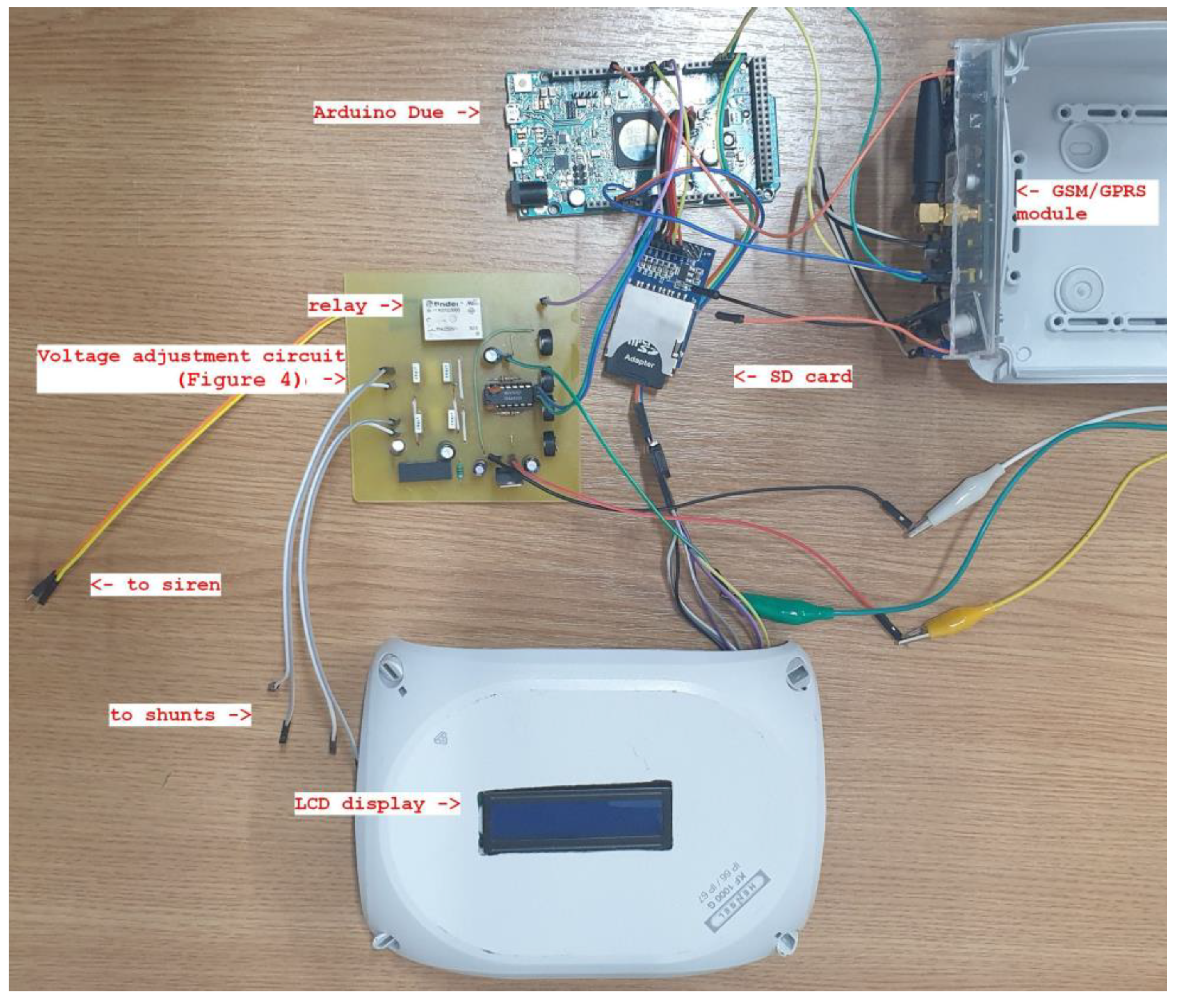
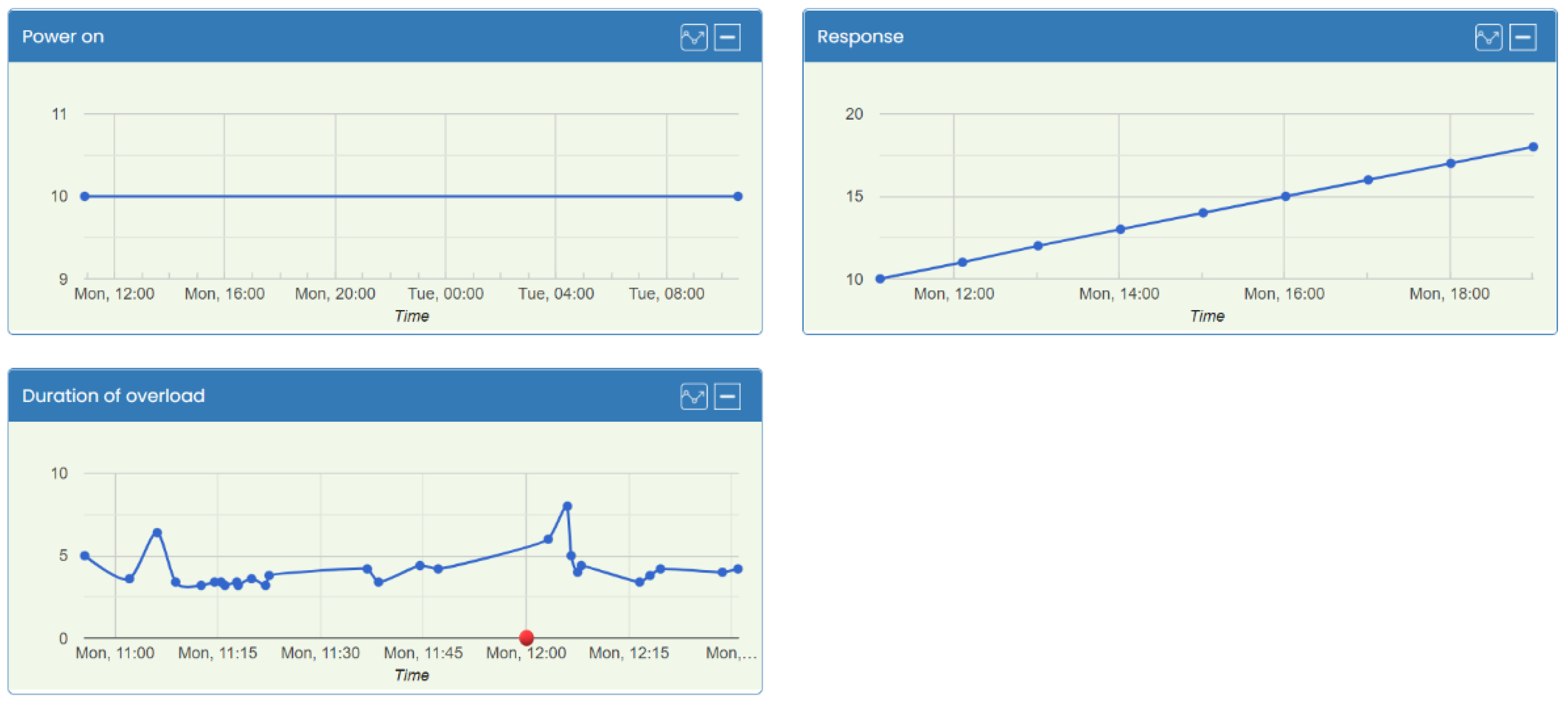
4. Experimental Results

Based on the previous considerations and using the mentioned components, we have developed a prototype system that detects and issues alarms when short circuits occur in the EKG-15 excavator. A device that is mounted inside the excavator and performs all the necessary functions, including sending the data to the cloud, is shown in Figure 7. The list of components used for the implementation of this device, together with the most important characteristics, is shown in Table 4.
As can be seen from Figure 7, the Arduino Due is used as a microprocessor platform. This platform has enough resources to meet all project requirements, and its cost does not differ significantly from other Arduino platforms. In addition to the previously mentioned components, the prototype also has an LCD display mounted on the device cover. During the development of the system, we used this display to show important information about the ongoing operation, acquired results and possible errors. In the other words, the display is used to facilitate the development of the system. Once all development phases are completed, including the device testing, this LCD is will no longer be needed.
Figure 7 also shows a printed circuit board on which the electrical scheme shown in Figure 4 is implemented. During the early prototype stage, it was decided to individually monitor each of the two motors in charge of moving the loading bucket, in such a way that the overload detection circuit would monitor the voltage from the shunts in the circuit of each motor. For this reason, the scheme in Figure 4 was implemented twice on the printed circuit board. However, since it is enough to determine the existence of too high current in the generator circuit from which both motors are powered, in practice, only one of these two channels is used.
The device depicted in Figure 7 was installed on an excavator in the surface mine of the RUP and its operation was monitored for a period of two months. No irregularities in the operation of the system were observed during that time. Nevertheless, the use of this system significantly reduced both the duration and the frequency of motor overloads. Before the installation of the system presented in this paper, the estimation of the overload occurrence was at least 40 times per work shift. Moreover, most of them were not timely and properly handled, causing the motor’s heating. Since there was not any reliable record or evidence of overloads, all information is based on assessments and experience of the maintenance team and experienced operators.

Performance Analysis

Performance analysis of the excavator after the proposed system installation was conducted based on the data sent to the cloud platform. Figure 8 shows some of these data that were collected immediately after the system installation.
As mentioned in the previous section, some of the data sent to the cloud relate to the information about the proper working of the device. The time instant at which the device is switched on or restarted is shown in the plot labeled as “Power on”. The IoT cloud platform automatically registers the time when data has arrived. By making use of this the device sends a predefined numerical value to trigger the platform to register and remember the moment when that data arrived at the cloud platform. In our prototype, this numerical value is set to 10. Therefore, in this plot, the value that is displayed (on the y-axis) is not relevant, but the time moment related to that value that is on the x-axis is important.
The plot labeled as “Response” indicates device activity, i.e., that it performs its function. Every hour, the device sends information in the form of the current time (hour) read from the RTC. If no data arrives over a period longer than one hour, it is necessary to check device functionality. This visual approach makes it easy to identify if any value between 0 and 23 is missing on this plot.
Data shown in the plot labeled as the “Duration of overload” are of primary importance. This plot shows the lengths of the detected overloads, expressed in seconds. Maintenance officers in charge of analyzing and determining the behavior of the operator in relation to motor overload are expected to analyze the data from this plot.
As stated earlier, the data shown in Figure 8 refer to the period of operation immediately after the commissioning of our system. As a result of the new system activation, operators of the excavator have encountered a new working environment in which the overload of the motors for more than 3 s was alarmed by the audio signal that can be heard inside the cabin. In comparison, previously, an operator had to observe an analog instrument located in their cabin, while simultaneously observing the behavior of the loading bucket in relation to the surrounding terrain. Since monitoring the loading bucket is a far more important task, it often happened that the operator did not notice the occurrence of motor overload. Furthermore, operators did not have any information about the duration of the overload.
By analyzing the data from the plots in Figure 8, based on the early spike above 5 s, it can be seen that initially, the operator on duty kept the motor in an overload condition somewhat longer. However, after a few of such events, operator’s reactions are faster in response to the occurrence of overload. After the initial learning phase, the duration of overload is shown to be constantly below 4 s. This reduced overload duration is a result of the operator stopping the motor very soon after the audio signal appears. Clearly, this protects the motor and extends its service life, because this prevents the motor from being overloaded for too long, which would lead to its burnout.
After the change of a shift and the arrival of a new operator (marked with a red dot on the diagram), a longer initial duration of motor overload repeats. After this, the new operator gets used to the new operating mode, which again leads a significant reduction in the overload duration.
It can be concluded that the implementation of this system has achieved the desired effect. Now, operators can focus on the loading bucket without having to look at an analog instrument to check how much current is being supplied to the motor. In the case the overload lasts longer than 3 s, the operator is immediately notified and can react promptly in order to protect the motor. During the one work shift, the overload occurred about 15 times, although the system was in the initial phase of use. According to the data obtained from the RUP, the overload occurrence is reduced by approximately 60%. The duration of each overload was far less than the safe margin of 9 s. Overall, 80% of them were under 5 s, which is a significant improvement compared to the many previously long-lasting overloads. Last but not least, there was not any motor malfunction during the experimental period.

5. Discussion

After a couple of months of operation and monitoring, we can conclude that the developed system met all functional requirements defined in the initial research phase. It has been shown that, after a period of adjustment by the operator, the duration of motor overload is reduced thanks to the use of the proposed system. Analysis showed a significant reduction in overload occurrence and an even greater reduction in its duration. Moreover, during the testing period, there was not any problem with the motor of the observed excavator.
However, the proposed solution only warns the operator when overload is detected but does not prevent the overload occurrence. Therefore, there is an opportunity for further improvement of the proposed device in this direction. Although the company’s management has demanded that the control electronics remain unchanged, the possibility of interrupting the motor supply current, in scenarios when critical events are detected, should be reconsidered. Implementing this measure would likely result in further efficiency improvements through fewer excavator outages, lower maintenance costs and improved productivity.
The proposed device sends information about the duration of the motor overload to the cloud. This information can be further used by the company’s management for analyzing overload events and determining the potential responsibility of the operator. The data collected can be also utilized for research and further improvement of the IoT device. For example, many predictive maintenance tools available in the literature are based on the motor current data. However, in order to fully support these applications, in addition to overload data, it is necessary to store information on changes in the motor current over time. Moreover, equipping the excavator with additional sensors and monitoring other variables is desirable and will be one of the future goals. Finally, the proposed device uses the HTTP protocol for data transmission, and in future versions of the device, integration of other IoT protocols such as the MQTT will be considered.

6. Conclusions

One of the most critical challenges facing the largest coal mine in Montenegro, the company “Rudnik uglja Pljevlja”, is the frequent failure of DC motors in EKG-15 excavators. Repairing these motors is very expensive and takes a long time to complete. During that time, productivity is reduced, due to the shutdown of that particular excavator. In order to reduce the probability of machine failures and thus increase productivity, in this paper, we propose an IoT device for monitoring DC motor overload. Functional requirements are defined in collaboration with the RUP company and then detailed implementation of the IoT device is provided. Experimental analysis has shown that after several months of using the device, the frequency and duration of overload are reduced. Additionally, during the testing period, any problem with the motor has not reported.
The paper also shows that IoT and sensing technology can be successfully applied to traditional industrial machines of older generations to improve their efficiency and productivity. Moreover, by analyzing a specific industrial problem, it is possible to develop solutions that are efficient and acceptable to companies. This is especially important in specific application domains such as the mining industry, where technologically more advanced solutions are not easy to develop or are not acceptable to companies for financial reasons.
Further work will be focused on improving the functionality of the proposed IoT device. Moreover, the possibility of equipping the excavator with additional sensors and integrating other IoT protocols will be considered. Additionally, the focus will be on the development of intelligent predictive maintenance techniques that will be based on collected data.

Author Contributions

Conceptualization, M.R. and B.K.; methodology, B.K.; software, M.R.; validation, M.R., Ž.Z. and B.K.; writing—original draft preparation, M.R. and Ž.Z.; writing—review and editing, M.R., Ž.Z. and B.K.; project administration, B.K. All authors have read and agreed to the published version of the manuscript.

Funding

This research was funded by Ministry of Economic Development, Montenegro, grant number 01-1865/6. The APC was funded by FASTER project.

Acknowledgments

We thank to company “Rudnik uglja Pljevlja” and its maintenance service team for the support during the work on this project, many useful discussions and assistance in mounting the IoT device on the excavator.

Conflicts of Interest

The authors declare no conflict of interest.

References

  1. Park, H.-S. Conceptual framework of construction productivity estimation. KSCE J. Civ. Eng. 2006, 10, 311–317. [Google Scholar] [CrossRef]
  2. Ng, F.; Harding, J.A.; Glass, J. An eco-approach to optimise efficiency and productivity of a hydraulic excavator. J. Clean. Prod. 2016, 112, 3966–3976. [Google Scholar] [CrossRef] [Green Version]
  3. Zhou, Q.; Chen, G.; Jiang, W.; Li, K.; Li, K. Automatically Detecting Excavator Anomalies Based on Machine Learning. Symmetry 2019, 11, 957. [Google Scholar] [CrossRef] [Green Version]
  4. Donnelly, G. Infrastructure Spending Could Be Hindered by a Shortage of Skilled Labor. Available online: https://finance.yahoo.com/news/infrastructure-spending-could-hindered-shortage-192951287.html (accessed on 27 April 2022).
  5. Ho, P.H.K. Labour and skill shortages in Hong Kong’s construction industry. Eng. Constr. Archit. Manag. 2016, 23, 533–550. [Google Scholar] [CrossRef]
  6. Juricic, B.B.; Galic, M.; Marenjak, S. Review of the Construction Labour Demand and Shortages in the EU. Buildings 2021, 11, 17. [Google Scholar] [CrossRef]
  7. Chang-Richards, Y.; Wilkinson, S.; Seville, E.; Brunsdon, D. Effects of a major disaster on skills shortages in the construction industry: Lessons learned from New Zealand. Eng. Constr. Archit. Manag. 2017, 24, 2–20. [Google Scholar] [CrossRef]
  8. Web Page of “Rudnik Uglja Pljevlja”. Available online: https://www.rupv.me/en (accessed on 1 May 2021).
  9. Sandzimier, R.J.; Asada, H.H. A Data-Driven Approach to Prediction and Optimal Bucket-Filling Control for Autonomous Excavators. IEEE Robot. Autom. Lett. 2020, 5, 2682–2689. [Google Scholar] [CrossRef]
  10. Chayama, K.; Fujioka, A.; Kawashima, K.; Yamamoto, H.; Nitta, Y.; Ueki, C.; Yamashita, A.; Asama, H. Technology of Unmanned Construction System in Japan. J. Robot. Mechatron. 2014, 26, 403–417. [Google Scholar] [CrossRef]
  11. Haga, M.; Hiroshi, W.; Fujishima, K. Digging control system for hydraulic excavator. Mechatronics 2001, 11, 665–676. [Google Scholar] [CrossRef]
  12. Zhao, Y.; Wang, J.; Zhang, Y.; Luo, C. A Novel Method of Soil Parameter Identification and Force Prediction for Automatic Excavation. IEEE Access 2020, 8, 11197–11207. [Google Scholar] [CrossRef]
  13. Tan, C.P.; Zweiri, Y.H.; Althoefer, K.; Seneviratne, L.D. Online soil parameter estimation scheme based on Newton-Raphson method for autonomous excavation. IEEE/ASME Trans. Mechatron. 2005, 10, 221–229. [Google Scholar] [CrossRef]
  14. Jud, D.; Hottiger, G.; Leemann, P.; Hutter, M. Planning and Control for Autonomous Excavation. IEEE Robot. Autom. Lett. 2017, 2, 2151–2158. [Google Scholar] [CrossRef]
  15. Azulay, O.; Shapiro, A. Wheel Loader Scooping Controller Using Deep Reinforcement Learning. IEEE Access 2021, 9, 24145–24154. [Google Scholar] [CrossRef]
  16. Allain, M.; Konduri, S.; Maske, H.; Pagilla, P.R.; Chowdhary, G. Blended Shared Control of a Hydraulic Excavator. IFAC-PapersOnLine 2017, 50, 14928–14933. [Google Scholar] [CrossRef]
  17. Davila Delgado, J.M.; Oyedele, L.; Ajayi, A.; Akanbi, L.; Akinade, O.; Bilal, M.; Owolabi, H. Robotics and automated systems in construction: Understanding industry-specific challenges for adoption. J. Build. Eng. 2019, 26, 100868. [Google Scholar] [CrossRef]
  18. Dadhich, S.; Bodin, U.; Andersson, U. Key challenges in automation of earth-moving machines. Autom. Constr. 2016, 68, 212–222. [Google Scholar] [CrossRef] [Green Version]
  19. Lee, J.S.; Ham, Y.; Park, H.; Kim, J. Challenges, tasks, and opportunities in teleoperation of excavator toward human-in-the-loop construction automation. Autom. Constr. 2022, 135, 104119. [Google Scholar] [CrossRef]
  20. Dubois, A.; Gadde, L.E. The construction industry as a loosely coupled system: Implications for productivity and innovation. Constr. Manag. Econ. 2010, 20, 621–631. [Google Scholar] [CrossRef]
  21. Hemami, A.; Hassani, F. An overview of autonomous loading of bulk material. In Proceedings of the 2009 26th International Symposium on Automation and Robotics in Construction, ISARC 2009, Austin, TX, USA, 24–27 June 2009; pp. 405–411. [Google Scholar]
  22. Bogue, R. What are the prospects for robots in the construction industry? Ind. Robot 2018, 45, 1–6. [Google Scholar] [CrossRef]
  23. Park, S.; Kim, J.; Lee, S.; Seo, J. A Comparative Analysis of Automated Machine Guidance and Control Systems for Trench Excavation. KSCE J. Civ. Eng. 2021, 25, 4065–4074. [Google Scholar] [CrossRef]
  24. Radonjić, M.; Vujnovic, S.; Krstić, A.; Zečević, Ž. IoT System for Detecting the Condition of Rotating Machines Based on Acoustic Signals. Appl. Sci. 2022, 12, 4385. [Google Scholar] [CrossRef]
  25. Ciancetta, F.; Fiorucci, E.; Ometto, A.; Fioravanti, A.; Mari, S.; Segreto, M.A. A Low-Cost IoT Sensors Network for Monitoring Three-Phase Induction Motor Mechanical Power Adopting an Indirect Measuring Method. Sensors 2021, 21, 754. [Google Scholar] [CrossRef] [PubMed]
  26. Loukatos, D.; Androulidakis, N.; Arvanitis, K.G.; Peppas, K.P.; Chondrogiannis, E. Using Open Tools to Transform Retired Equipment into Powerful Engineering Education Instruments: A Smart Agri-IoT Control Example. Electronics 2022, 11, 855. [Google Scholar] [CrossRef]
  27. Radonjić, M.; Zečevic, Ž.; Krstajić, B. Iot System for Short-Circuit Detection of Dc Motor at Ekg-15 Excavator. In Proceedings of the First International Conference ETIMA 2021, Štip, North Macedonia, 19–21 October 2021; pp. 222–230. [Google Scholar]
  28. Gardašević, G.; Veletić, M.; Maletić, N.; Vasiljević, D.; Radusinović, I.; Tomović, S.; Radonjić, M. The IoT Architectural Framework, Design Issues and Application Domains. Wirel. Pers. Commun. 2016, 92, 127–148. [Google Scholar] [CrossRef]
  29. Arduino. Available online: https://www.arduino.cc (accessed on 12 May 2021).
  30. UoM IoT Platform. Available online: http://www.iot.ucg.ac.me/ (accessed on 10 February 2022).
  31. NI4OS-Europe Project (National Initiatives for Open Science in Europe). Available online: https://ni4os.eu/ (accessed on 23 December 2021).
  32. TLP 7920 Datasheet, Toshiba Electronic Devices & Storage Corporation. Available online: https://toshiba.semicon-storage.com/ap-en/semiconductor/product/optoelectronics/isolation-amplifiers-isolated-delta-sigma-modulators/detail (accessed on 12 May 2021).
  33. Pmod SD: Full-Sized SD Card Slot. Available online: https://store.digilentinc.com/pmod-sd-full-sized-sd-card-slot (accessed on 15 November 2021).
  34. SIM808 GPRS/GSM+GPS Shield v1.1. Available online: https://www.elecrow.com/wiki/index.php?title=SIM808_GPRS/GSM%2BGPS_Shield_v1.1 (accessed on 15 November 2021).
  35. Telenor Montenegro, Device Settings, GPRS Settings. Available online: https://www.telenor.rs/en/consumer/support/device-settings/ (accessed on 8 November 2021).
Figure 1. Development phases of the proposed IoT system.
Electronics 11 01555 g001
Figure 2. Cloud platform as the center of data flow.
Electronics 11 01555 g002
Figure 3. Block diagram of the proposed solution.
Electronics 11 01555 g003
Figure 4. Circuit for adjusting the voltage generated on the shunt to the requirements of the Arduino platform.
Electronics 11 01555 g004
Figure 5. AT commands that are executed during the initialization procedure.
Electronics 11 01555 g005
Figure 6. C function for sending data to the cloud.
Electronics 11 01555 g006
Figure 7. Prototype of DC motor overload detection system for excavator EKG-15.
Electronics 11 01555 g007
Figure 8. Data visualization within UoM IoT platform cloud service.
Electronics 11 01555 g008
Table 1. Functional requirements for the system design.
  • The control electronics and the current operation mode of the excavator should not be affected in any way.
2.
The system should be capable of warning the operator when an overload occurs.
3.
Information related to the occurrence of the short-circuit current should be saved for the purpose of later analysis and processing.
4.
The device should be equipped with a communication unit so that the system can be connected to the cloud platform for the remote monitoring and analysis.
Table 2. Experimentally determined voltage at the output of the TLP7920 for some values of input.
Vin [mV]−80−60−40−2020406080
Vtlp [mV]−605−453−301−152158308460612
Table 3. Experimentally determined voltage at the output of the circuit for adjusting the voltage generated on the shunt.
Vin [mV]−80−60−40−2020406080
Vout [V]0.130.480.831.191.92.262.622.98
Table 4. Specification of components used for design of the prototype of DC motor overload detection system for excavator EKG-15.
ComponentSpecification
Arduino DueMicrocontrollerAT91SAM3X8E, operating voltage 3.3 V, input voltage 7–12 V, digital I/O pins 54 (of which 12 provide PWM output), analog input pins 12, analog output pins 2 (DAC), flash memory 512 KB, SRAM 96 KB (two banks: 64 KB and 32 KB), clock speed 84 MHz.
SD card32 GB, micro SD card Class 10
SD card adapterPmodSD by Digilent, Full-sized SD card slot, No limitation on file system or memory size of SD card used, 1-bit and 4-bit communication, 12-pin Pmod connector with SPI interface.
GSM-GPRS modemQuad-band 850/900/1800/1900 MHz, GPRS multi-slot class12 connectivity: max. 85.6 kbps(down-load/up-load), Controlled by AT Command, Supply voltage range 5 V ~ 12 V, Supports 3.0 V to 5.0 V logic level, Low power consumption, 1 mA in sleep mode, Standard Micro SIM Card.
LCD16 character × 2 lines; 5 × 8 dots; single power supply (5 V ± 10%); I2C interface
TLP7920 optically isolated amplifierSigma-delta (Σ-Δ) analog-to-digital converter technology/Optical coupled isolation amplifier
Real-Time Clock
DS3231 RTC chip
Real-Time Clock Counts Seconds, Minutes, Hours, Date of the Month, Month, Day of the Week, and Year, with Leap-Year Compensation Valid Up to 2100, Accuracy ± 2 ppm from 0 °C to +40 °C, Accuracy ± 3.5 ppm from −40 °C to + 85 °C, Fast (400 kHz) I2C Interface, Battery-Backup Input for Continuous Timekeeping, 3.3 V Operation
Publisher’s Note: MDPI stays neutral with regard to jurisdictional claims in published maps and institutional affiliations.

