
Research on Voltage Stabilizing Control Strategy of Critical Load in Unplanned Island Based on Electric Spring


Abstract
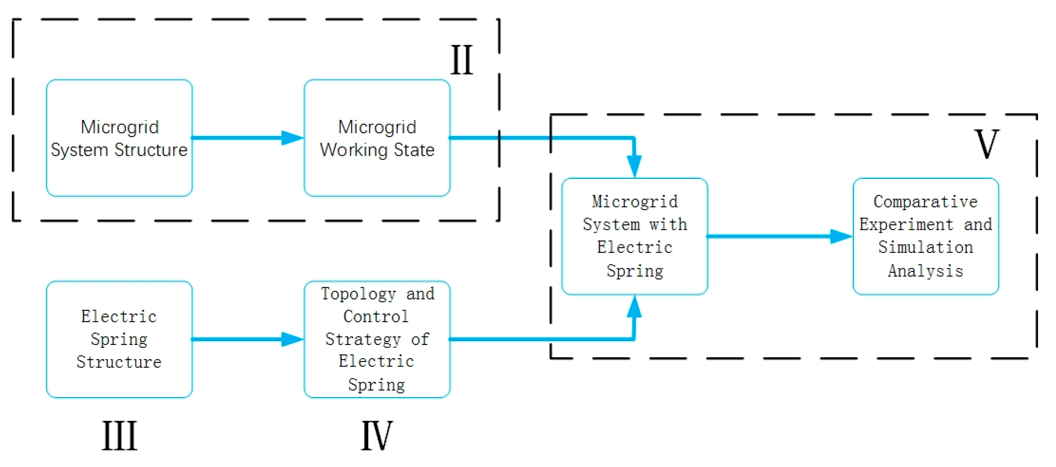
:1. Introduction
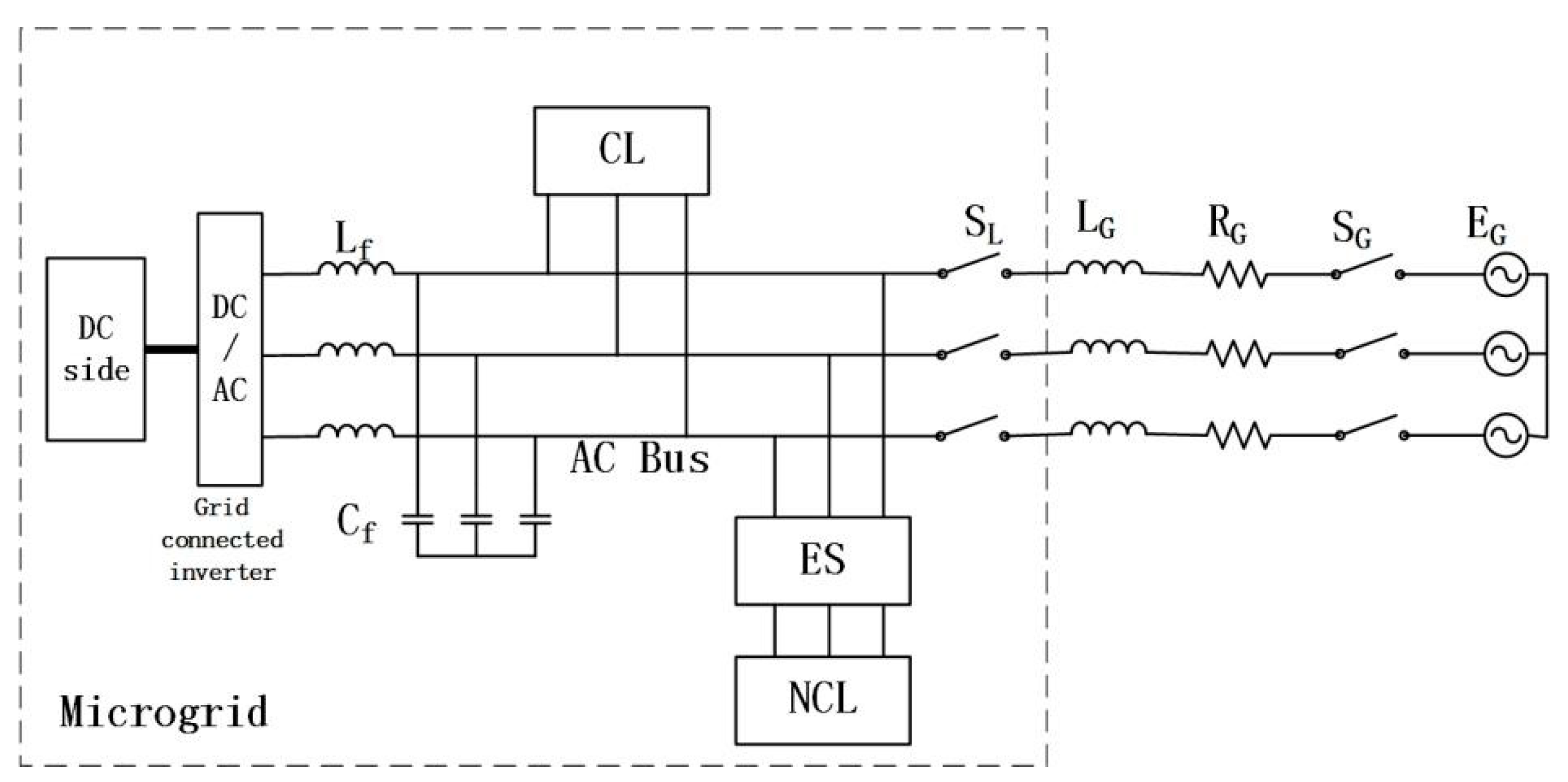
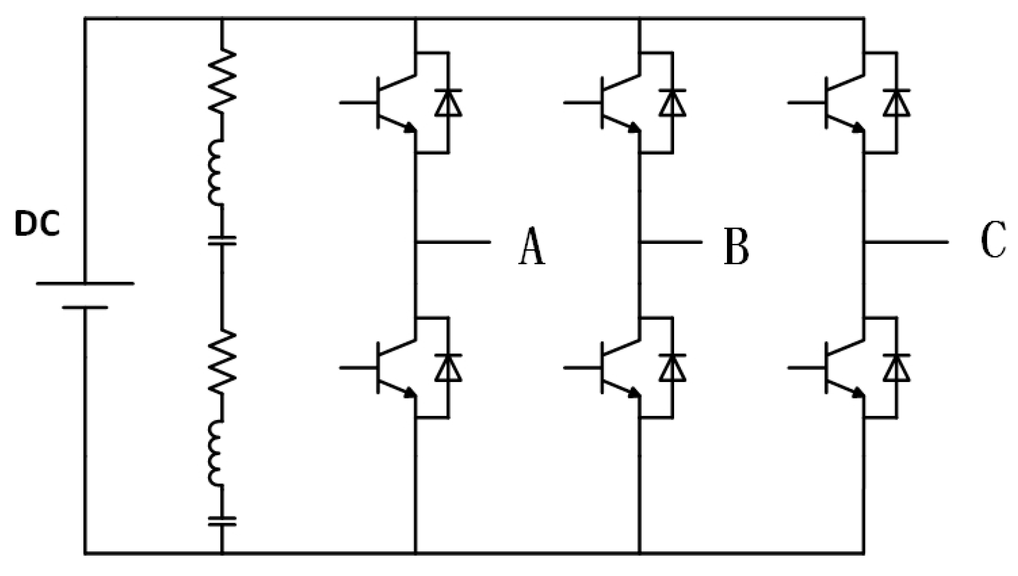
- We built an AC/DC hybrid microgrid, established a grid connected inverter model, realized the connection between microgrid and distribution network, and enabled the microgrid to switch seamlessly between grid connected and off grid states.
- We briefly introduce the basic principle and working state of electric spring.
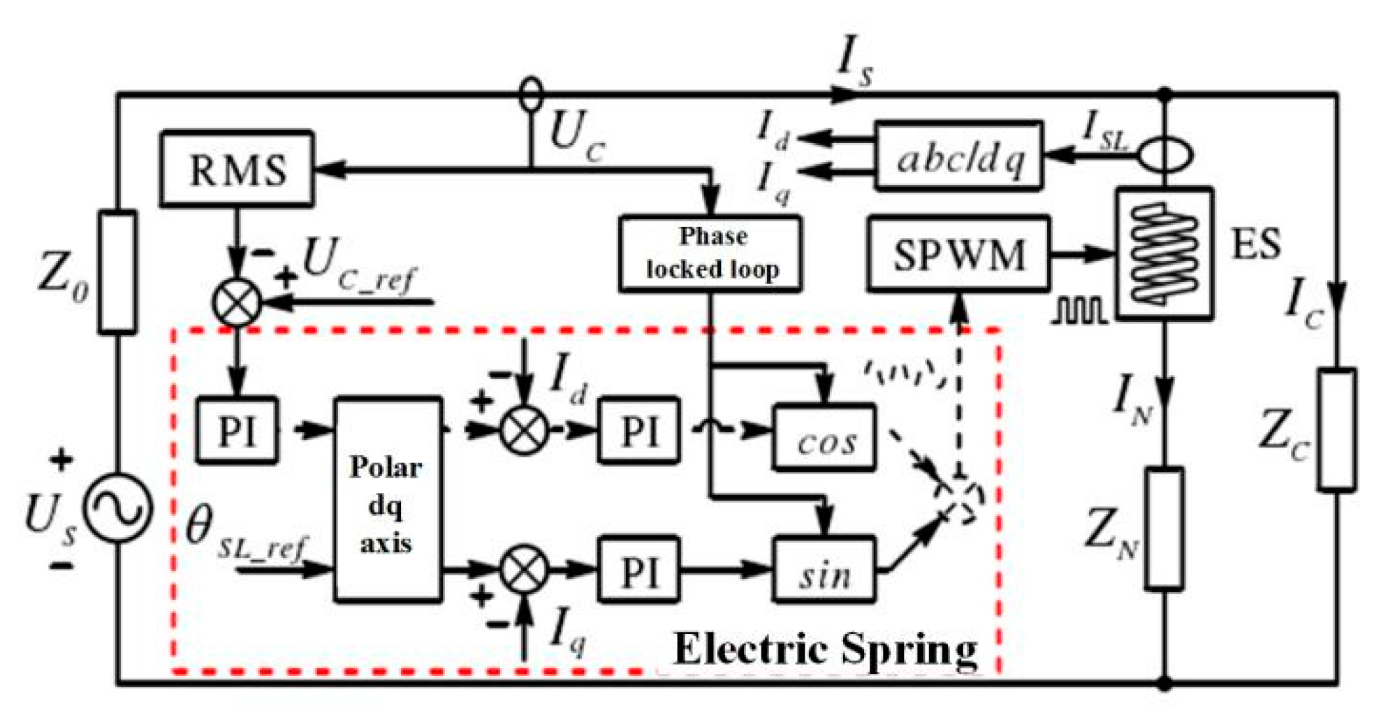
- A three-phase electric spring was constructed using the basic idea of an electric spring, and a decoupling control method based on a double closed loop is provided.
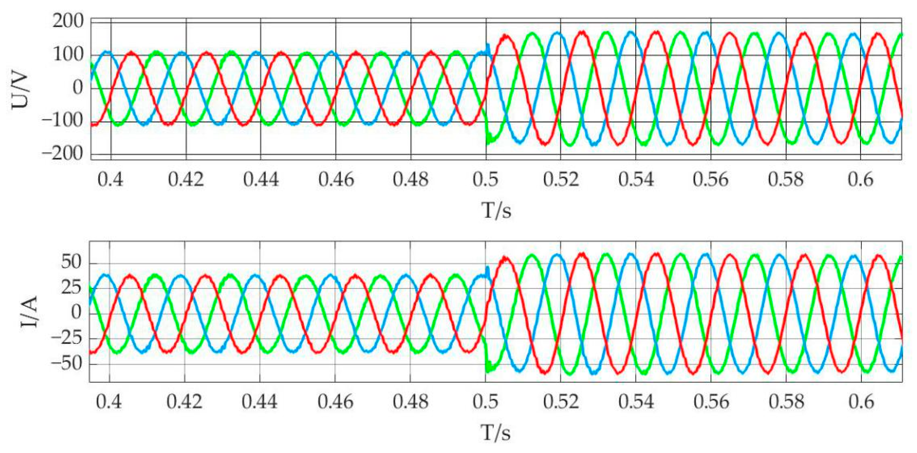
- The electric spring simulation model and microgrid parallel/off grid switching simulation model were built with MATLAB/Simulink simulation software, and they were integrated to verify that the proposed control strategy based on electric spring can ensure the voltage stability of critical loads when an unplanned island occurs in the microgrid. The simulation findings show that when an unplanned island occurs in the microgrid, the microgrid power is insufficient or overflows owing to the offline distribution network, the bus voltage changes, and the voltage at the main load changes as a result of the bus voltage. The electric spring balances the voltage and current at the critical load, ensuring the critical load’s stable operation.
2. Microgrid Structure and Working State
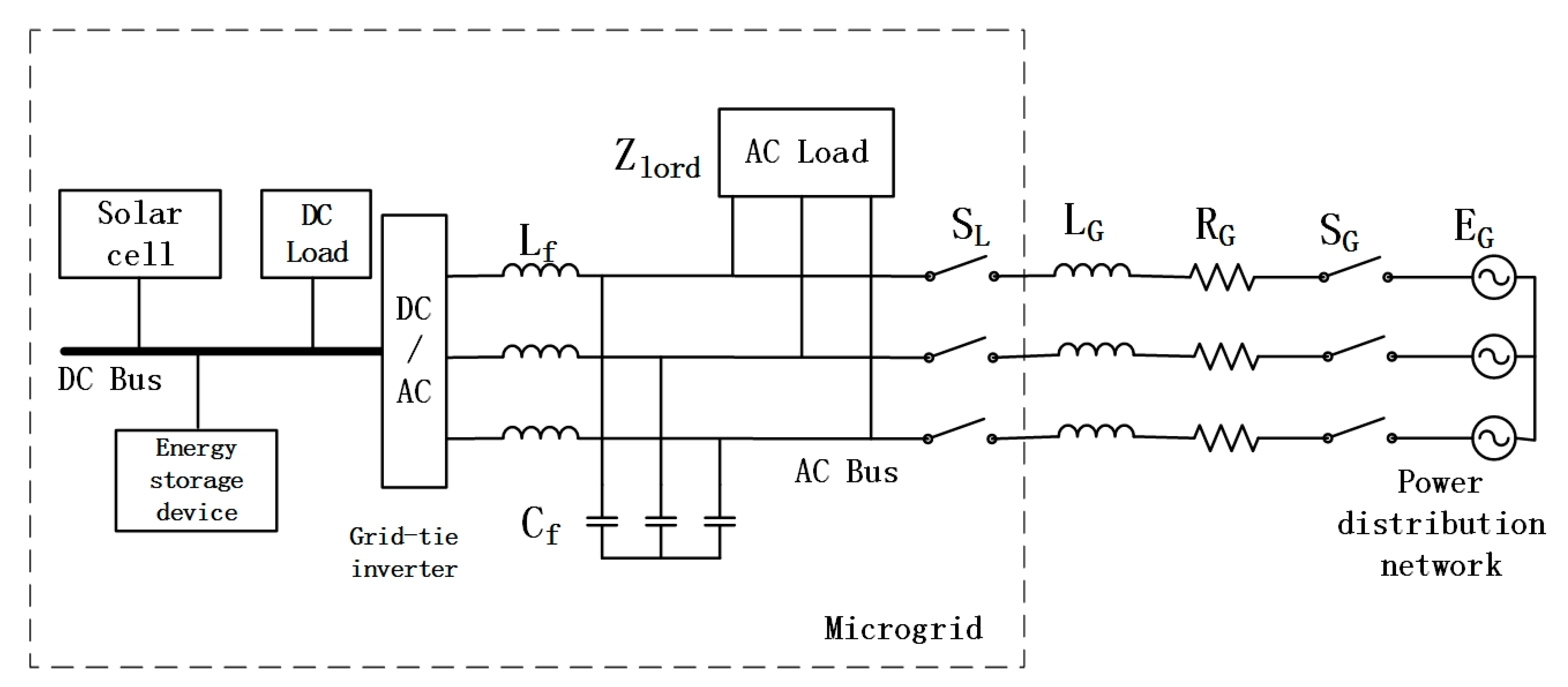
2.1. Microgrid System Structure
2.2. Microgrid Working State
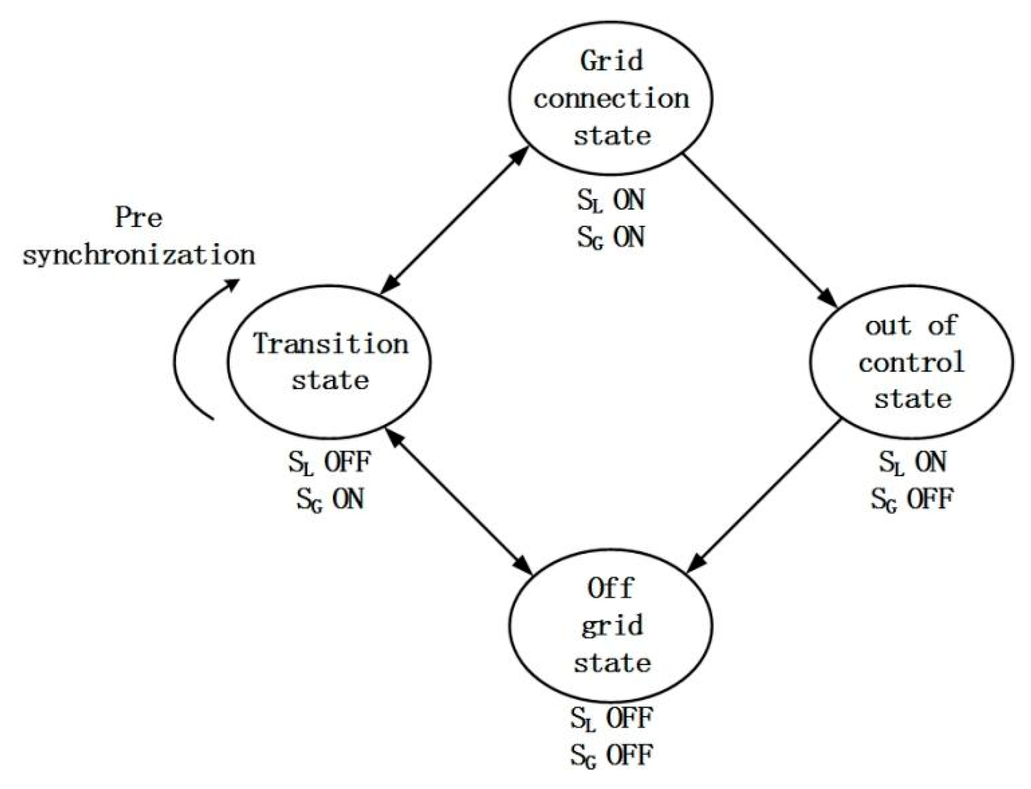
- When both SG and SL are all closed, the microgrid system operates in the grid connected state, the inverter adopts PQ control, and the distributed generation and distribution network jointly supply energy for the local load.
- When SG and SL are all disconnected, the microgrid system operates in an off-grid state, with the inverter set to v/F control and the distributed power supply in the microgrid supplying electricity to the local load independently.
- When the SG is closed and the SL is disconnected, the system is in a transitional state. Before the SL takes effects, the grid-connected inverter will perform preprocessing to ensure the stability during switching. When switching from off grid to grid connection, the inverter receives the action signal, performs pre-synchronization processing, adjusts the inverter’s output voltage to synchronize with the distribution network’s voltage, makes grid connection preparations, and then closes the SL to complete grid connection; grid connection is switched to off grid. When receiving the action signal, the inverter performs power preprocessing, redistributes the power on the AC bus, reduces the power proportion of the distribution grid in the system, and ensures the stability of the whole system when the distribution grid is disconnected.
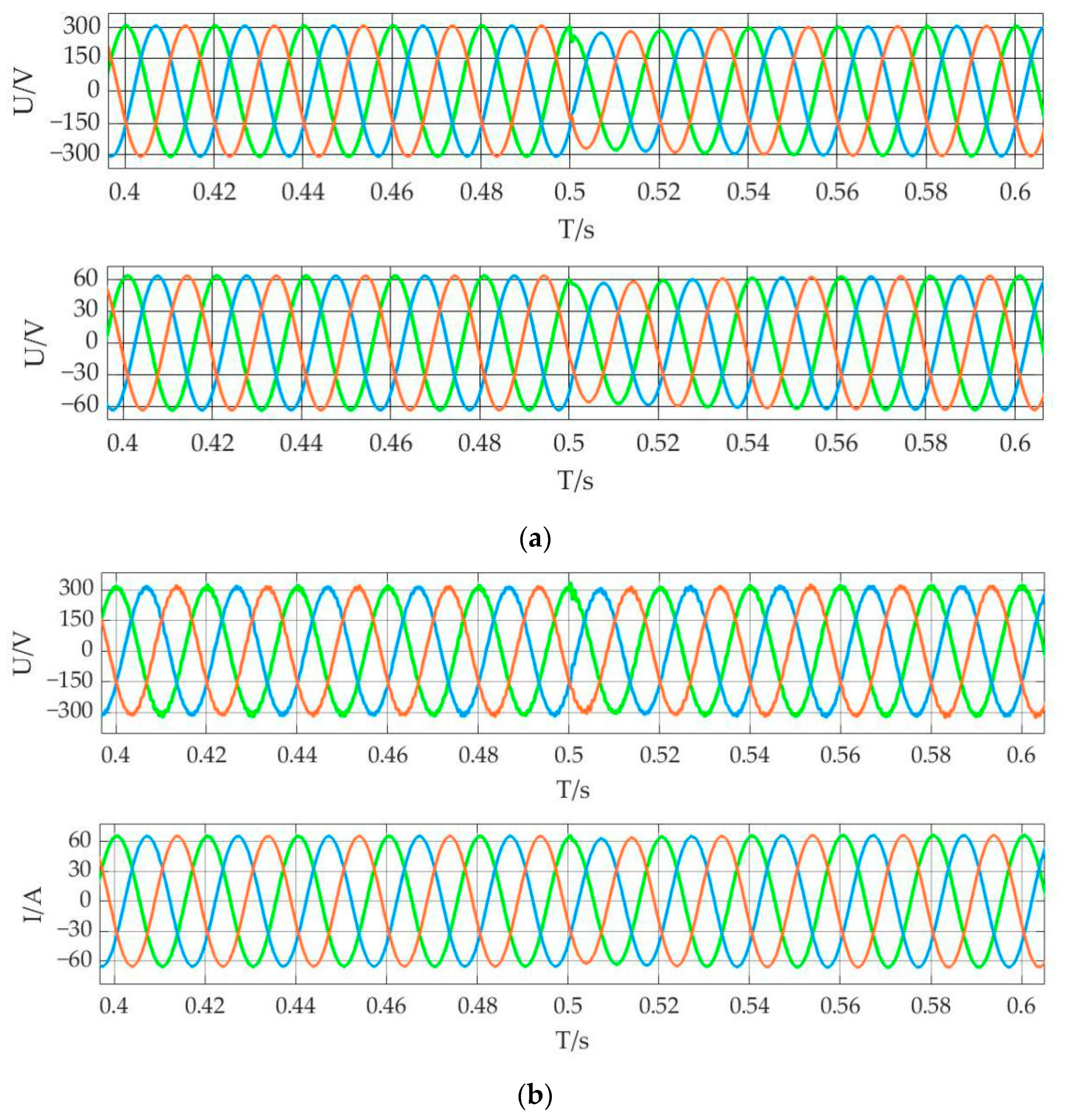
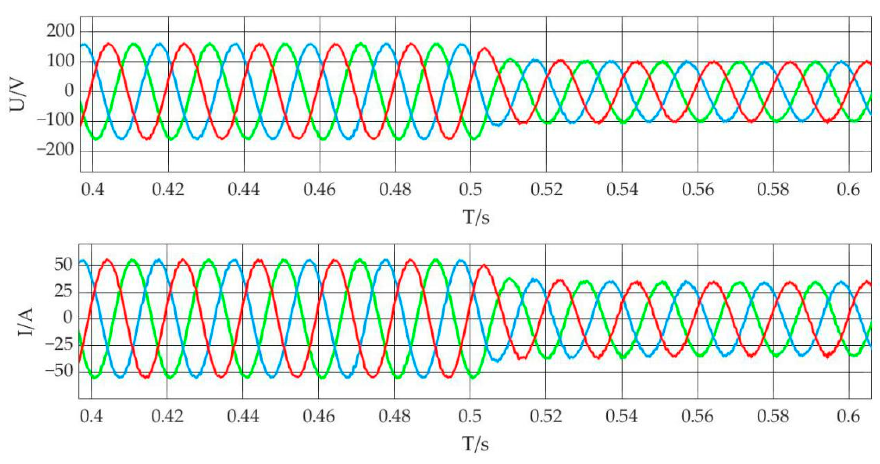
- When SL is closed but SG is disconnected due to protection action, the island state at this time is generated by the action of protection switch, which is not part of the typical microgrid’s operation plan, making it an unplanned island. When an unplanned island occurs, the inverter is unable to redistribute power since it does not receive the off-grid switching preparatory action signal, and the distribution network goes off-line, causing the entire microgrid system to fail. The power balance of the system is disrupted within a short period of time, resulting in large fluctuations in the voltage and current of the microgrid bus, which are out of control. Although the grid connected inverter receives the islanding detection signal, so that the control strategy of the inverter is switched from PQ control to v/F control during grid connection, due to the large power imbalance of the microgrid system, if only v/F is used to control the bus voltage, large fluctuations will occur, making power supply reliability impossible to maintain. The power supply of AC load cannot be assured at this time. Therefore, this paper introduces the electric spring as the protection measure in case of unplanned islanding to ensure the voltage stability of critical loads in case of fluctuations caused by unplanned islanding.
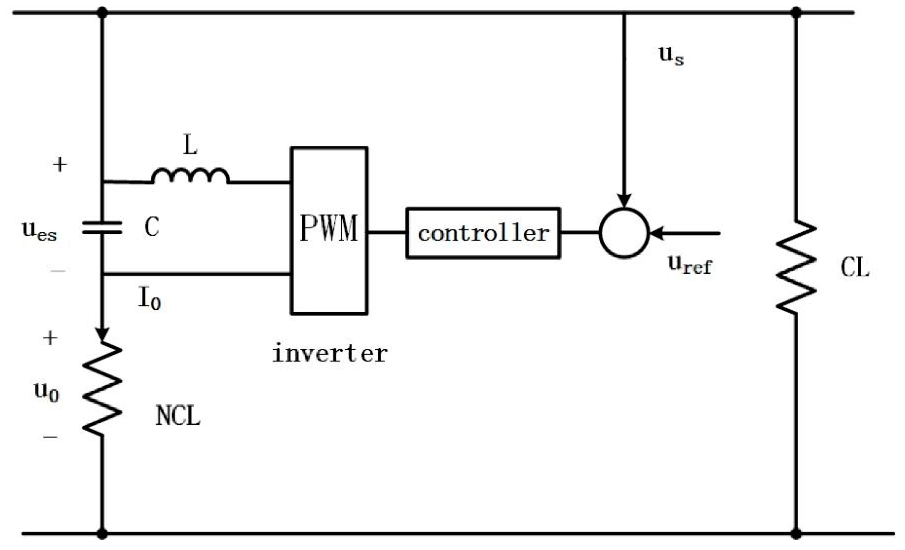
3. Electric Spring Structure
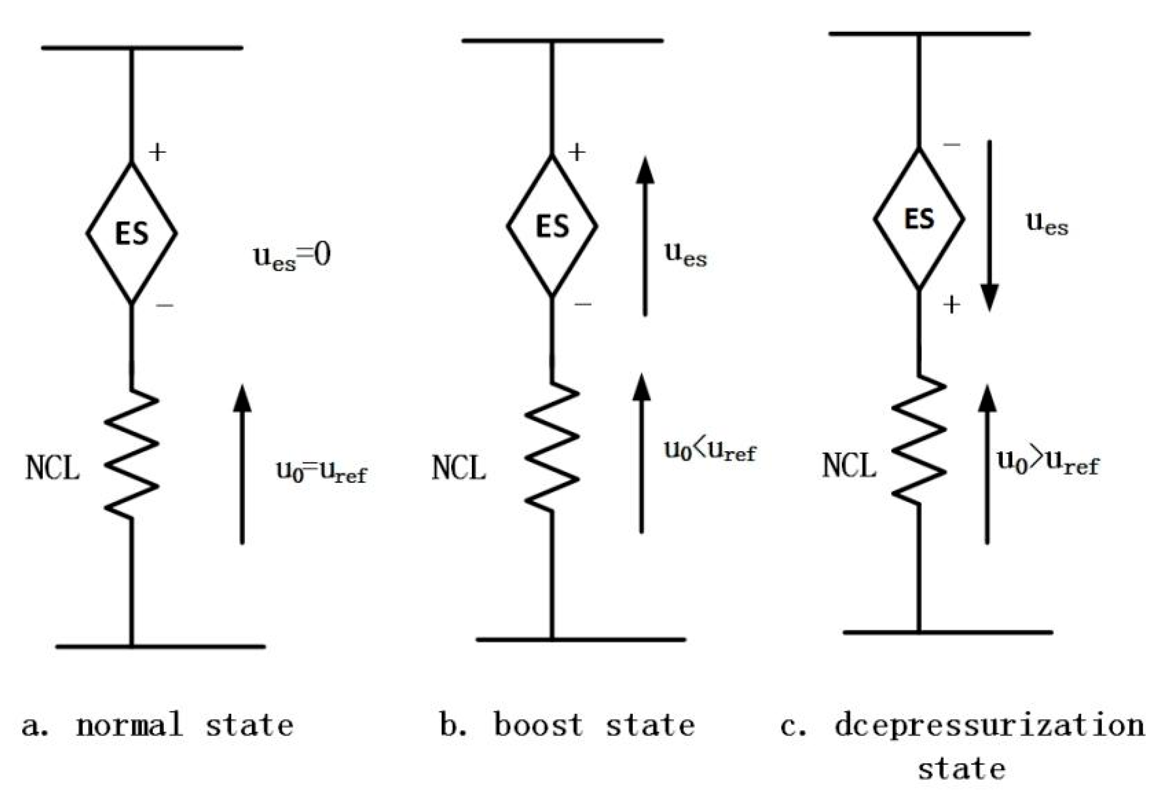
3.1. Working Condition of Electric Spring
3.2. Operation Mode of Electric Spring
4. Topology and Control Strategy of Electric Spring
5. Comparative Experiment and Simulation Analysis
5.1. Simulation Analysis of the First Kind of Unplanned Island
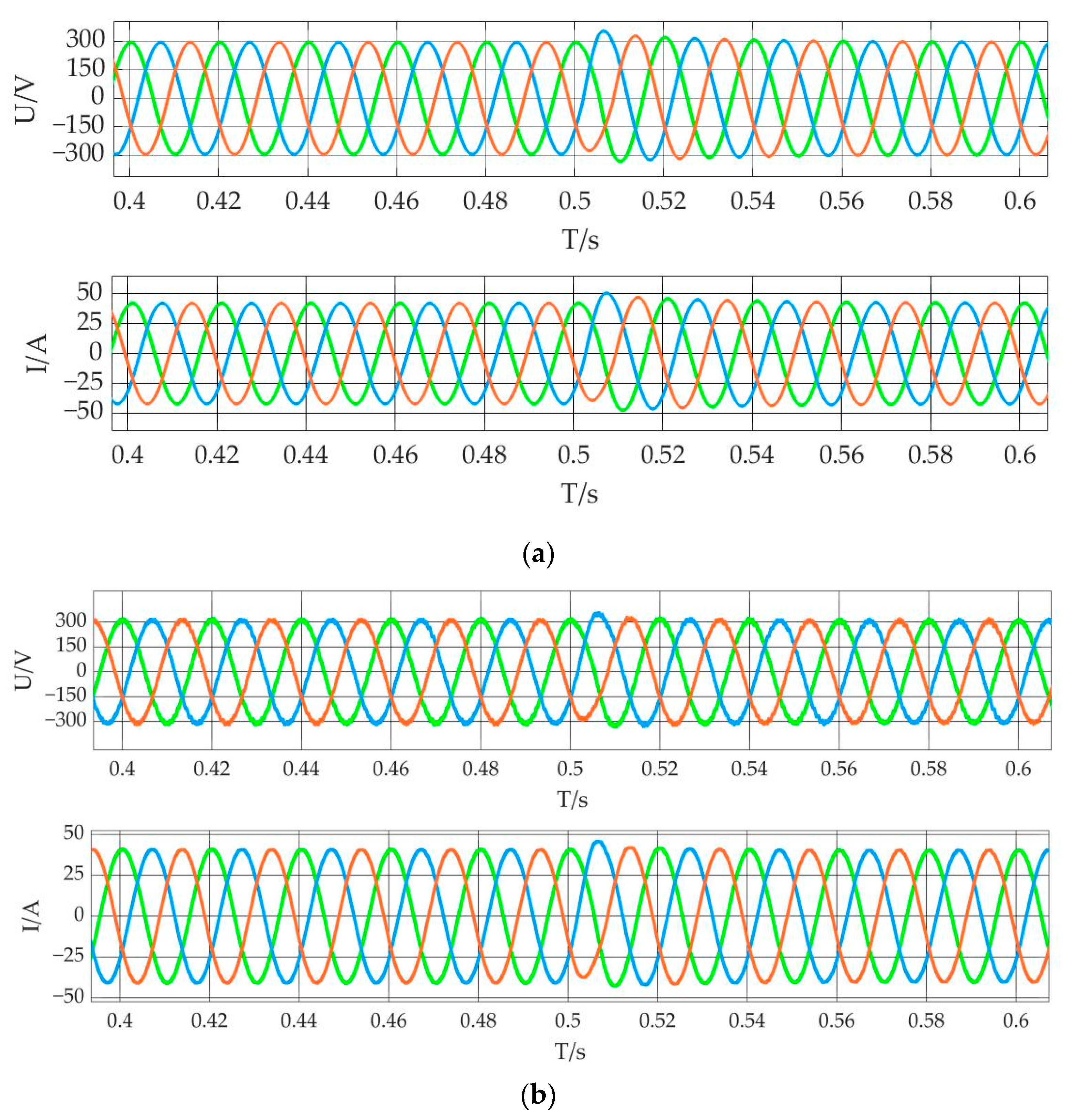
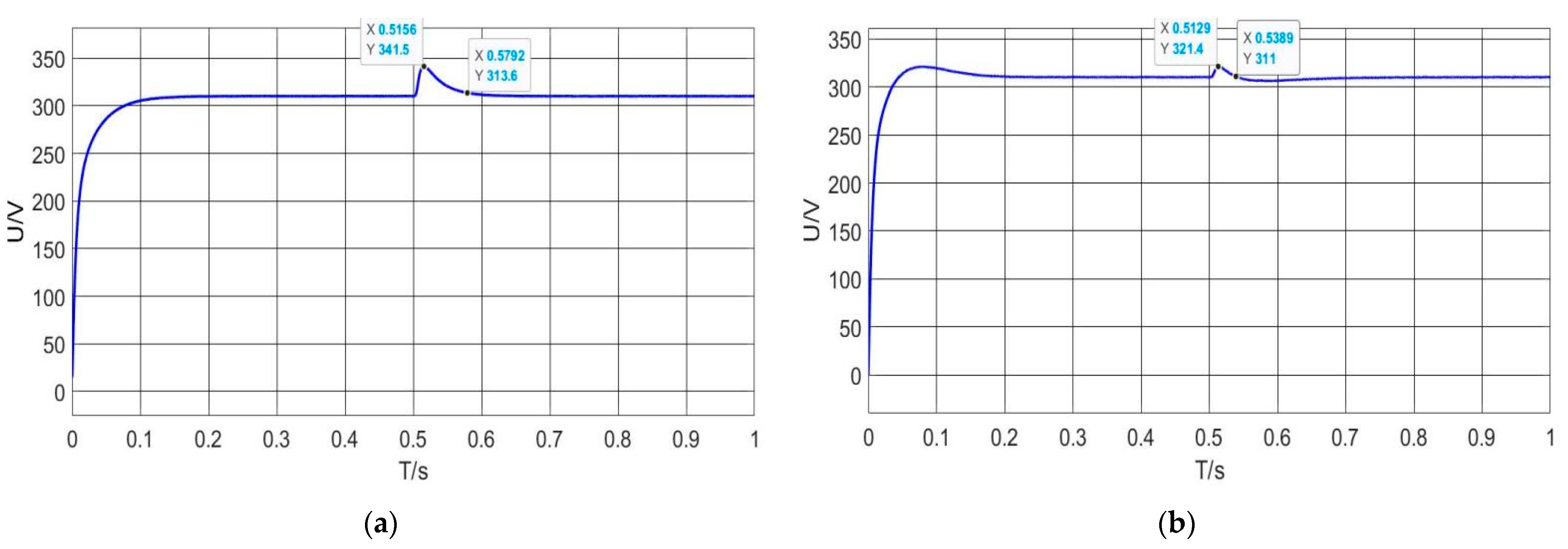
5.2. Simulation Analysis of the Second Kind of Unplanned Island
6. Conclusions
- When unplanned islanding occurs, the control technique based on three-phase electric spring described in this research is effective and can meet the goal of voltage stabilizing control of important loads.
- In different island states, the electric spring behaves differently, but it can protect the critical load in both boost and step-down states.
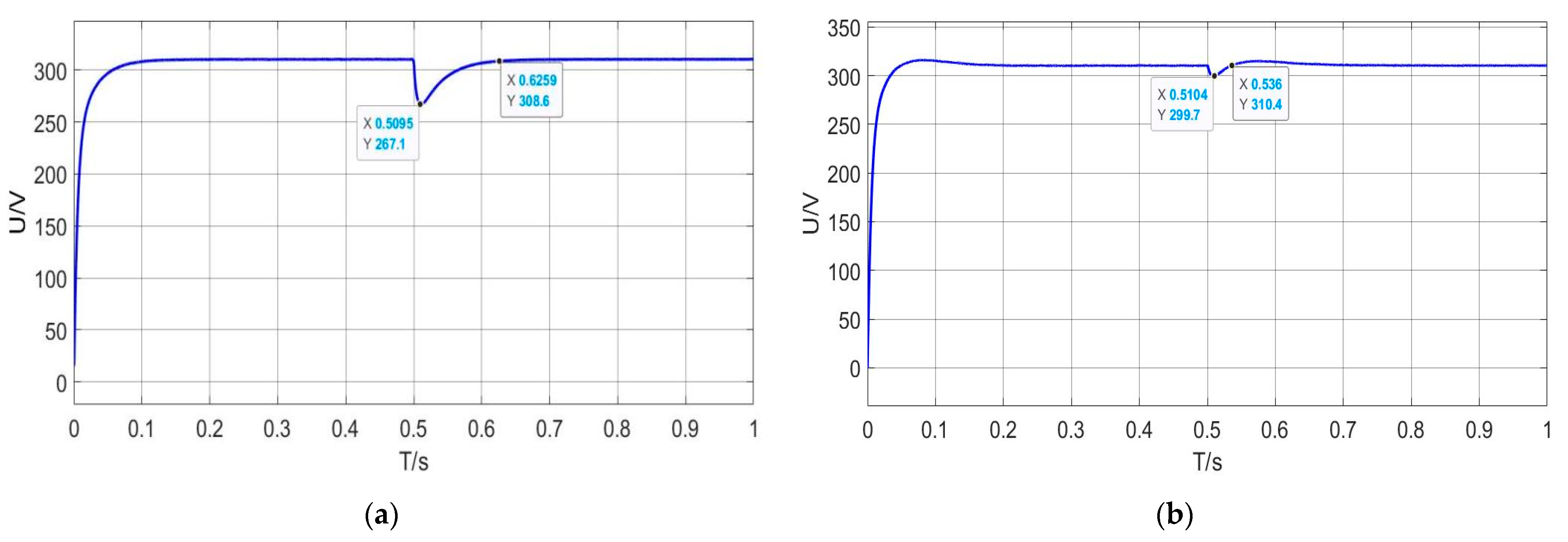
- Compared with v/F control, electric spring control can reduce the amplitude change about 60% and cut the recovery stability time about 50%. As a result, as compared to traditional control, the voltage stabilizing control technique for critical loads employing electric spring is faster and more effective.
Author Contributions
Funding
Conflicts of Interest
References
- Chengshan, W.; Peng, L. Development and challenges of distributed generation, microgrid and intelligent distribution network. Power Syst. Autom. 2010, 34, 10–14, 23. [Google Scholar]
- Hongli, Z.; Fusuo, L.; Wei, L. Transient voltage mismatch risk and load shedding method of high permeability photovoltaic access to power grid. Power Syst. Prot. Control 2018, 46, 158–164. [Google Scholar]
- Pengwei, S.; Ye, Z.; Fan, Z. Quantitative assessment of system stability risk of photovoltaic power station after entering the isolated island. Power Eng. Technol. 2018, 37, 93–97. [Google Scholar]
- Mekhilef, S.; Rahim, N.A. Implementation of grid-connected photovoltaic system with power factor control and islanding detection. In Proceedings of the 2004 IEEE 35th Annual Power Electronics Specialists Conference, Aachen, Germany, 20–25 June 2004; IEEE Cat. No. 04CH37551. pp. 1409–1412. [Google Scholar]
- Lo, K.-Y.; Chen, Y.-M. Design of a Seamless Grid-Connected Inverter for Microgrid Applications. IEEE Trans. Smart Grid 2020, 11, 194–202. [Google Scholar] [CrossRef]
- Meng, X.; Liu, J.; Liu, Z.; An, R. An Improved PLL Based Seamless Transfer Control Strategy. In Proceedings of the 2018 International Power Electronics Conference (IPEC-Niigata 2018—ECCE Asia), Niigata, Japan, 20–24 May 2018; pp. 3251–3256. [Google Scholar] [CrossRef]
- Xia, L.; Hai, L. A Seamless Transfer Strategy Based on Multi-master and Multi-slave Microgrid. In Proceedings of the 2018 9th IEEE International Symposium on Power Electronics for Distributed Generation Systems (PEDG), Charlotte, NC, USA, 25–28 June 2018; pp. 1–5. [Google Scholar] [CrossRef]
- Li, C.; Savulak, J.; Reinmuller, R. Unintentional Islanding of Distributed Generation—Operating Experiences from Naturally Occurred Events. IEEE Trans. Power Deliv. 2014, 29, 269–274. [Google Scholar] [CrossRef]
- Sharma, A.; Sunitha, R. Unintentional islanding detection in microgrid. In Proceedings of the 2017 International Conference on Energy, Communication, Data Analytics and Soft Computing (ICECDS), Chennai, India, 1–2 August 2017; pp. 2519–2523. [Google Scholar] [CrossRef]
- Cheng, Z.; Lai, W.; Gangui, Y.; Qi, J. Seamless switching control strategy of distributed generation considering unplanned Island. J. Electrotech. 2017, 32, 129–139. [Google Scholar]
- Tongwen, W.; Jingdong, X.; Qinghua, S.; Min, X.; Bin, Y.; Xuedong, L.; Chang, Y. Research on unplanned islanding of photovoltaic power generation system. Power Syst. Prot. Control. 2020, 48, 173–180. [Google Scholar]
- Wang, C.; Mei, S.; Yu, H.; Cheng, S.; Du, L.; Yang, P. Unintentional Islanding Transition Control Strategy for Three-/Single-Phase Multimicrogrids Based on Artificial Emotional Reinforcement Learning. IEEE Syst. J. 2021, 15, 5464–5475. [Google Scholar] [CrossRef]
- Issa, W.R.; Khateb, A.H.E.; Abusara, M.A.; Mallick, T.K. Control Strategy for Uninterrupted Microgrid Mode Transfer during Unintentional Islanding Scenarios. IEEE Trans. Ind. Electron. 2018, 65, 4831–4839. [Google Scholar] [CrossRef] [Green Version]
- Vignesh, S.S.; Udayakumar, G. An integrated three layer hierarchical control and protection of photovoltaic generators in microgrid. In Proceedings of the 2016 International Conference on Emerging Trends in Engineering, Technology and Science (ICETETS), Pudukkottai, India, 24–26 February 2016; pp. 1–6. [Google Scholar] [CrossRef]
- Liang, L.; Hou, Y.; Hill, D.J.; Hui, S.Y.R. Enhancing resilience of microgrids with electric spring. IEEE Trans. Smart Grid 2018, 9, 2235–2247. [Google Scholar] [CrossRef]
- Hui, S.Y.; Lee, C.K.; Wu, F.F. Electric Springs—A New Smart Grid Technology. IEEE Trans. Smart Grid 2012, 3, 1552–1561. [Google Scholar] [CrossRef] [Green Version]
- Fagen, Y.; Chun, W. Review of Electric Spring: Principle, Topologies, Control and Applications. Power Syst. Technol. 2019, 43, 174–184. [Google Scholar]
- Xunyu, L.; Yuqi, P.; Xinyuan, Z.; Xiaotian, X.; Yang, Z.; Gang, M. Photovoltaic grid connection stability method based on voltage and power factor of electric spring. Electr. Autom. 2021, 43, 55–58, 61. [Google Scholar]
- Chaudhuri, N.R.; Lee, C.K.; Chaudhuri, B.; Hui, S.R. Dynamic modeling of electric Springs. IEEE Trans. Smart Grid 2014, 5, 2450–2458. [Google Scholar] [CrossRef]
- Keqin, B.; Haoqiang, W.; Qiming, C.; Haiyan, C. Passive control strategy of electric spring based on E-L model. High Volt. Technol. 2021, 10, 1–10. [Google Scholar] [CrossRef]
- Luo, X.; Akhtar, Z.; Lee, C.K.; Chaudhuri, B.; Tan, S.C.; Hui SY, R. Distributed Voltage Control with Electric Springs: Comparison with STATCOM. IEEE Trans. Smart Grid 2015, 6, 209–219. [Google Scholar] [CrossRef] [Green Version]
- Le, F.; Jianping, Z.; Dajun, M.; Jian, Z.; Xiangyi, G.; Cambridge, Y. electric spring control based on improved droop control and real-time stability of critical load voltage. Mot. Control. Appl. 2020, 47, 84–90. [Google Scholar]
- Giacomuzzi, S.; Buja, G.; Bertoluzzo, M.; Wang, Q. Dynamic Behavior Analysis and Control of Reactive Electric Springs. In Proceedings of the 2020 IEEE 29th International Symposium on Industrial Electronics (ISIE), Delft, The Netherlands, 17–19 June 2020; pp. 833–838. [Google Scholar] [CrossRef]
- Dong, B.W.; Xue, H.; Hu, Y.J. Voltage Stabilization Control Method of Renewable Energy Power Supply System Based on Electric Spring. Electr. Meas. Instrum. 2020, 57, 100–107. [Google Scholar]
- Khamis, A.K.; Zakzouk, N.E.; Abdelsalam, A.K.; Lotfy, A.A. Decoupled control strategy for electric springs: Dual functionality feature. IEEE Access 2019, 7, 57725–57740. [Google Scholar] [CrossRef]
- Zheng, Y.; Zhang, C.; Hill, D.J.; Meng, K. Consensus control of electric springs using a back-to-back converter for voltage regulation with ultra-high renewable penetration. J. Mod. Power Syst. Clean Energy 2017, 5, 897–907. [Google Scholar] [CrossRef] [Green Version]
- Ray, S.; Nag, T.; Biswas, S.; Chatterjee, D. Modified Electric Spring Module Based Voltage and Frequency Control for Power flow Mechanism. In Proceedings of the 2020 IEEE 17th India Council International Conference (INDICON), New Delhi, India, 10–13 December 2020; pp. 1–6. [Google Scholar] [CrossRef]
- Yang, Y.; Tan, S.; Hui, S. Voltage and frequency control of electric spring based smart loads. In Proceedings of the 2016 IEEE Applied Power Electronics Conference and Exposition (APEC), Long Beach, CA, USA, 20–24 March 2016; pp. 3481–3487. [Google Scholar]
- Soni, J.; Panda, S.K. Electric spring for voltage and power stability and power factor correction. IEEE Trans. Ind. Appl. 2017, 53, 3871–3879. [Google Scholar] [CrossRef]
- Wang, Q.S.; Cheng, M.; Jiang, Y.L. Harmonics suppression for critical loads using electric springs with current-source inverter. IEEE J. Emerg. Sel. Top. Power Electron. 2016, 4, 1362–1369. [Google Scholar] [CrossRef]
- Yang, T.; Mok, K.T.; Ho, S.S.; Tan, S.C.; Lee, C.K.; Hui, R.S. Use of integrated photovoltaic-electric spring system as a power balancer in power distribution networks. IEEE Trans. Power Electron. 2019, 34, 5312–5324. [Google Scholar] [CrossRef]
- Chen, X.; Hou, Y.; Tan, S.C.; Lee, C.K.; Hui, S.Y.R. Mitigating voltage and frequency fluctuation in microgrids using electric springs. IEEE Trans. Smart Grid 2015, 6, 508–515. [Google Scholar] [CrossRef] [Green Version]


| AC bus voltage | 380 V |
| AC bus frequency | 60 Hz |
| CL Rated power | 1000 W |
| NCL Rated power | 1000 W |
| Internal resistance | Ron | 0.001 Ω |
| Snubber resistance | Rs | 105 Ω |
| Sunbber capacitance | Cs | ∞ |
| Resistance | R | 1 Ω |
| Inductance | L | 0.001 H |
| Capacitance | C | 10−6 F |
| Proportional | Kp | 0.1 |
| Integral gain | Ki | 1 |
| Output limits | - | [106,−106] |
| Sample time | t | 50 × 10−6 |
Publisher’s Note: MDPI stays neutral with regard to jurisdictional claims in published maps and institutional affiliations. |
© 2021 by the authors. Licensee MDPI, Basel, Switzerland. This article is an open access article distributed under the terms and conditions of the Creative Commons Attribution (CC BY) license (https://creativecommons.org/licenses/by/4.0/).
Share and Cite
Wang, H.; Song, C.; Yue, Y.; Zhao, H. Research on Voltage Stabilizing Control Strategy of Critical Load in Unplanned Island Based on Electric Spring. Electronics 2022, 11, 80. https://doi.org/10.3390/electronics11010080
Wang H, Song C, Yue Y, Zhao H. Research on Voltage Stabilizing Control Strategy of Critical Load in Unplanned Island Based on Electric Spring. Electronics. 2022; 11(1):80. https://doi.org/10.3390/electronics11010080
Chicago/Turabian StyleWang, Hongjun, Chunchao Song, Youjun Yue, and Hui Zhao. 2022. "Research on Voltage Stabilizing Control Strategy of Critical Load in Unplanned Island Based on Electric Spring" Electronics 11, no. 1: 80. https://doi.org/10.3390/electronics11010080
APA StyleWang, H., Song, C., Yue, Y., & Zhao, H. (2022). Research on Voltage Stabilizing Control Strategy of Critical Load in Unplanned Island Based on Electric Spring. Electronics, 11(1), 80. https://doi.org/10.3390/electronics11010080