Article

Distributed Economic Control for AC/DC Hybrid Microgrid

1
Key Laboratory of Control Theory and Application for Complex Systems in Tianjin, Tianjin University of Technology, Tianjin 300384, China
2
College of Engineering and Technology, Tianjin Agricultural University, Tianjin 300392, China
*
Author to whom correspondence should be addressed.
Electronics 2022, 11(1), 13; https://doi.org/10.3390/electronics11010013
Submission received: 23 November 2021 / Revised: 17 December 2021 / Accepted: 20 December 2021 / Published: 22 December 2021

Abstract

:
In this paper, a new double-layer droop control mode for island AC/DC microgrids is proposed to realize autonomous and cost-effective operation. The optimal power reference iterative algorithm is used to realize the internal active power distribution in the subnet. On this basis, secondary frequency and voltage adjustments are introduced to realize the economic operation, autonomy and stability of the subnet. At the microgrid level, the local control strategy of cost micro increment deviation is designed to optimize the exchange power between subnets. The cooperation of the two can realize the global economic operation of the microgrid, as well as voltage following and frequency regulation in the subnet. Based on the hybrid AC/DC microgrid simulation model, the effectiveness of the proposed method is verified.

1. Introduction

As the utilization of distributed power sources such as photovoltaic and wind power generation has become increasingly widespread, microgrid, as an important medium for connection dispersed power supply and main network, has attracted a lot of attention [1,2,3,4]. Hybrid AC/DC microgrid has incomparable advantages over single DC microgrid and AC microgrid [5]. For example, it performs better in terms of lowering the power grid’s transformation level, preserving load access, and ensuring the power grid’s stable operation [6,7].
In order to improve the capacity of grid connection and consumption of microgrid, many studies have been carried out on the control mode of hybrid microgrid. To preserve the stability of power grid operation, the traditional control mode in microgrids adopts droop control. However, although the traditional droop control can realize the primary grid regulation of voltage and active power, it overlooks the operation cost of distributed generation, resulting in resource waste [8]. Therefore, realizing the economic operation of microgrid while maintaining the stability of power grid is an important issue to be considered in microgrid operation control [9].
Scholars have previously recommended using droop control, voltage regulation, and frequency response to improve microgrid stability [10,11,12,13,14]. For example, the author of [15] proposed self-learning fuzzy sliding mode control based on droop strategy to reduce bus voltage fluctuation and improve output voltage quality. In [16], reactive power sharing is also improved based on adaptive fuzzy logic control. By assessing the use priority and load relevance of different distributed generators [17], presented a frequency control technique based on dynamic cutting machine to lower the load in different frequency ranges. In [18], a power coordination control method combining normalized droop control and adaptive control is proposed, which maintains the power mutual support between microgrids and reduces the voltage and frequency deviation [19]. The operation control of DC microgrid is divided into multiple levels according to different time scales. Finally, an improved DC bus voltage control strategy is proposed to improve the stability and reliability of the system. The above papers merely enhance the microgrid’s ability to operate in a stable manner, but ignores the microgrid’s ability to operate economically.
In the current microgrid operation management, people have gradually taken the economic cost and environmental cost of distributed generation into account, and developed the microgrid hierarchical control to improve the rationality of distributed generation in power distribution [20]. This study addresses not only the economic operation of microgrids, but also the impact of economic operation control on power grid operation voltage and frequency, in order to assure power grid stability. This work proposes a double-layer droop control structure to provide autonomous, economical, and reliable microgrid operation. The key contribution of this paper is as follows:
  • Based on the distributed control theory of discrete consistency, the communication between distributed generators is realized, and the overall connection model is established.
  • To achieve the optimal power allocation of distributed generation in subnet, an improved droop control approach based on an optimal power reference iterative algorithm is provided.
  • An enhanced cost micro increment droop control approach based on the interconnection converter is presented to realize the economic operation between subnetworks.
The main structure of this paper is as follows: the first chapter introduces the current research status on this topic, and the second chapter discusses the basic structure of microgrid and the related principles of distributed control; the third chapter examines the control strategy of hybrid AC/DC microgrid, which includes inter group control and sub network control; the fourth chapter presents some relevant case studies to demonstrate the efficacy of the suggested strategy; and the fifth chapter summarizes the article.

2. Distributed Control Principle of Hybrid Microgrid System Structure

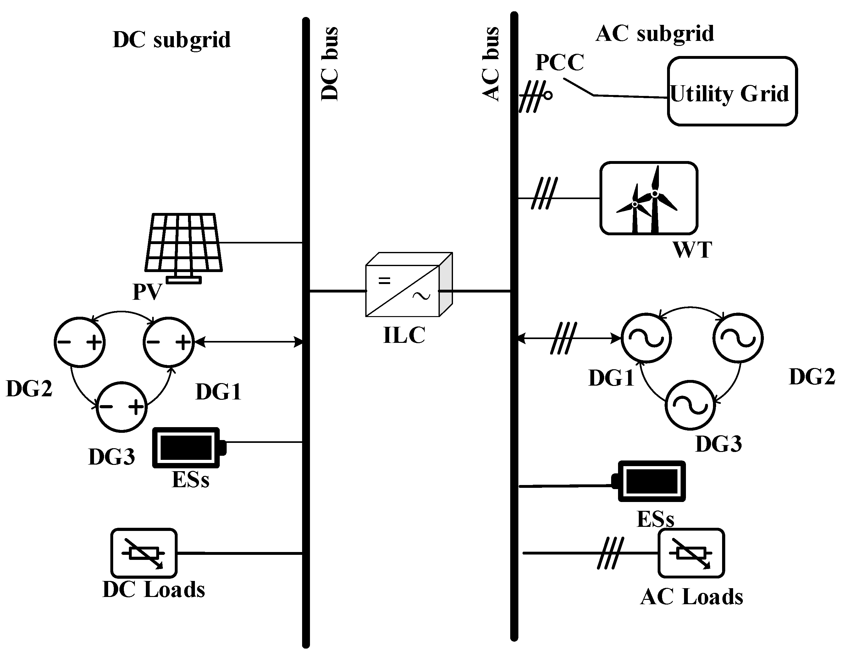
2.1. Hybrid Microgrid System Structure

Figure 1 depicts the control architecture of an AC/DC hybrid microgrid. As can be seen from it, distributed generation, renewable energy, energy storage and load are, respectively, connected to DC bus and AC bus. DC bus and AC bus are connected through a two-way interconnection converter, and the main network is connected to the AC microgrid side through common coupling points. Renewable energy such as wind turbine and photovoltaic use maximum frequency tracking control to ensure that power generation is not interrupted. The cost characteristics of various distributed energy sources vary, and the resulting generating cost is what makes up the hybrid microgrid’s operation cost.

2.2. Graph Theory

For a communication network with n nodes, a directed communication network can be established G = ( V , E ) . Where V = {1, 2, 3,…, N}, V is a set of nodes in a directed graph. E ( V × V ) , E is an edge set composed of ordered pairs of different nodes. N i = { j V ; ( i , j ) E } , Ni is the set of adjacent nodes of node i. adjacency matrix A = [ a i j ] R N × N , if j N i , a i j = 1 ; otherwise, a i j = 0 . This means that if i is the adjacency point of j, node i can obtain information from node j. Degree matrix D = diag { d i } R N × N , and degree matrix D is a diagonal matrix. It satisfies if j N i , and then there is d i j = a i j . Then, the Laplace matrix of digraph G can be expressed as: L = D A . Figure 2 depicts the communication topology between distributed generators in this paper:

2.3. Discrete Consistency Principle

The nodes of a hybrid AC/DC microgrid’s distributed generation interact with adjacent nodes to transmit the active power, frequency and voltage information of distributed generation, and the state of the next time is determined by the state information between adjacent nodes and local nodes, ensuring that all nodes achieve consistent convergence.
The voltage, current, active power, and other information utilized in information exchange between nodes become consistency variables of the consistency protocol, which are represented by the variable x. The discrete consistency principle can therefore be stated using the following Equation (1):
x i ( k + 1 ) = x i ( k ) + μ i ( k )
where x i ( k + 1 ) ,   x i ( k ) is the state variable of node i at k + 1 time and k time, respectively; μ i ( k ) is the input variable of node i. Then, the input variable μ i ( k ) can be expressed as:
μ i ( k ) = j N i a i j ( x j ( k ) x i ( k ) )
where, N i is the set of all nodes adjacent to node i; a i j is the communication weight between nodes i and j. Where the communication weight between nodes is a i j can be constructed by metropolis method, or expressed as:
a i j = { 1 ( m a x [ l i i , l j j ] + 1 ) ,   j N i 1 j N i a i j ,                                         i = j 0     ,                                                                       e l s e
when the system satisfies the Equation (4), the states between nodes reach consensus convergence.
l i m k | x j ( k ) x i ( k ) | = 0

2.4. Optimal Power Reference Iterative Algorithm

Although the traditional droop control can realize the primary regulation of power and voltage, it cannot balance the output of distributed generation according to the cost when considering the economic cost of distributed generation. Therefore, the traditional algorithm needs to be improved. To cope with the economic operation of distributed generation, an optimal power reference iterative algorithm is proposed in this study.
When all distributed generators are operating within their capacity range, the optimal distributed power of distributed generators can be obtained by Lagrange function:
P i = P s g + i = 1 n β i 2 α i 2 α i i = 1 n 1 2 α i β i 2 α i
where P i is the optimal allocated power of distributed generation i. P s g is the power exchange consumption between the microgrid energy storage system, load and main network after accounting for the power emitted by photovoltaics and wind generator.
Thus, the optimal power reference value is:
P i o p = ( 2 α ) 1 ( 2 A P L β 1 n )
L is the Laplace matrix in the communication topology; A is the adjacency matrix; 1 n is an n-order square matrix whose elements are all 1; it can be seen from the communication connection relationship between distributed nodes that when the system reaches the steady state, it must exist for each node when lim t ( P i o p P i ) = 0 , that is, P i o p = P i Therefore, in the steady state, the Equation (7) can be derived:
α 1 ( P 1 + β 1 2 α 1 ) = α 2 ( P 2 + β 2 2 α 2 ) = = α n ( P n + β n 2 α n )
The power among the distributed generators will gradually attain equilibrium in the steady state, as shown by the above expression, which can further obtain:
I C 1 = I C 2 = = I C n
According to the equal micro increment criterion, when the reference power of each node reaches the optimal power reference value of the current node, the cost micro increment balance can be realized and the purpose of power grid economic operation can be realized.

3. Hybrid AC/DC Microgrid Control Strategy

Equal micro increment criterion: when the cost increment of each distributed generation in the power system is the same, the operation cost of the power system is the lowest.
In the economic dispatch, the equal micro increment criterion is frequently used to minimize the operation cost of microgrid.
The control objective of hybrid microgrid can be expressed as:
{ m i n i = 1 N I C i ( P i ) i = 1 N I C i ( P i ) = P E E S + P W T + P P V + P L + P M A I N P i , m i n P i P i , m a x
I C i is the cost micro increment of the ith distributed generation, P W T is the power value output by the fan at the maximum power point, P L a c is the active power consumed by microgrid load, P M A I N is the exchange power between the microgrid and the main network.
{ P E E S = | P E E S |   P E E S . m i n | P E E S | P E E S P E E S = | P E E S |   P E E S < | P E E S | P E E S . m a x
where P E E S stored power capacity, with upper and lower limits for energy storage; Set a reference value P E E S for the energy storage device. When the stored power is less than or equal to this value, charge the energy storage device, and vice versa. P E E S . m i n , P E E S . m a x are the upper and lower limits of the energy storage capacity of the energy storage device, respectively.
In order to minimize the operation cost of microgrid, its internal shall meet the equal micro increment criterion, that is:
I C 1 = I C 2 = I C 3 = α P + β

3.1. AC Subnet Control Target

The control model of AC subnet is as follows:
{ m i n i = 1 N a c I C i ( P a c , i ) i = 1 N a c I C i ( P a c , i ) = P E E S + P W T + P L a c + P M A I N P i , m i n a c P a c , i P i , m a x a c
I C i is the cost micro increment of the ith distributed generation, P W T is the power value output by the fan at the maximum power point, P L a c is the active power consumed by the AC subnet load, and P M A I N is the exchange power between the AC subnet and the main network.
The equal increment criterion must be met in the AC subnet to minimize the AC subnet’s operation cost, which is:
I C 1 = I C 2 = I C 3 = α i P i + β i
It is vital to modify the voltage and frequency since the economic dispatching of microgrid would certainly cause voltage and frequency deviation. The equation for adjusting AC voltage is as follows:
l i m t ( U a c U a c ) = 0
U a c is the reference voltage of public AC bus without economic dispatching, U a c is voltage value of public AC bus after economic dispatching.
l i m t ( ω a c ω a c ) = 0
ω a c is the frequency reference value of AC subnet, and ω a c is the AC microgrid frequency to be adjusted.

3.2. DC Subnet Control Target

The economic dispatching model of DC subnet is similar to that of AC subnet, and the economic dispatching model of DC subnet is equivalent to:
{ m i n j = 1 N d c C j ( P d c , j ) j = 1 N d c C j ( P d c , j ) = P E E S + P P V + P L d c P j , m i n d c P d c , j P j , m a x d c
where P E E S is a DC energy storage device, and its storage capacity expression is consistent with that of AC subnet, which will not be repeated here. P P V is the power value of photovoltaic output at maximum power, P L d c is the power consumed by the DC subnet load.
To minimize the operation cost of the DC subnet, the equal increment criterion shall be met in the DC subnet, which is:
I C 1 = I C 2 = I C 3 = α j P j + β j
The active power distribution of DC microgrid will also affect the bus voltage of DC microgrid, therefore, the bus voltage of DC subnet is adjusted as follows:
lim t ( U d c U d c ) = 0
U d c is the reference voltage of public AC bus without economic dispatching, U d c is the voltage value of the public AC bus after economic dispatching.

3.3. Microgrid Inter Group Control Targets

The optimal economic operation can be realized in the DC subnet and the AC subnet by the economic dispatching in the subnet. However, the power sharing between the AC and DC subnets is not taken into account in the foregoing control objectives. Therefore, the power load demand for one subnet is too high, while the other subnet has a big surplus. As a result, an economic dispatching model across subnets is provided utilizing the equal micro increment criterion in order to balance the power flow between microgrids and implement power sharing at the overall microgrid level:
I C a c ¯ = I C d c ¯
The above equation indicates that the mean value of AC subnet cost micro increment is equal to that of DC subnet. According to the equal micro increment criterion, the minimal operating cost between subnets is determined at this time. When there is more than one subnet, the mean value of cost increment of each subnet shall be equal.

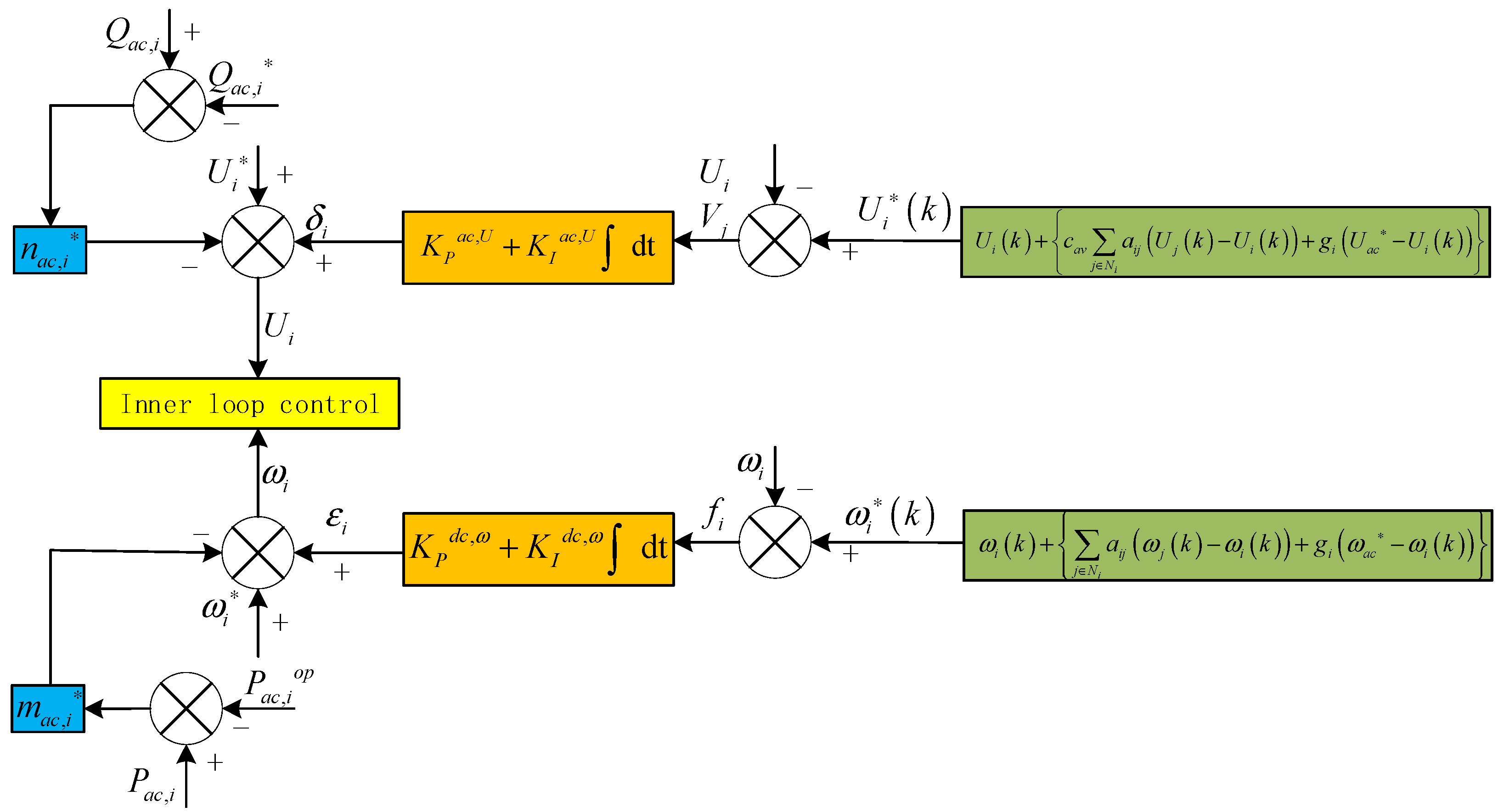
3.4. AC Subnet Control Strategy

Droop control is frequently used to regulate power distribution and voltage equalization in AC networks. Active frequency control (F–P) and reactive voltage control are the mainstays of classic droop control (V–Q). They mainly realize the distribution of power and the primary regulation of frequency and voltage. The following is an example of droop control:
ω i = ω i m a c , i ( P a c , i P a c , i )
U i = U i n a c , i ( Q a c , i Q a c , i )
where, ω i ω i is the frequency and reference frequency of the ith distributed power supply, respectively; P a c , i , P a c , i are the active power and active power reference values of the ith distributed generation, respectively; U i , U i is the voltage and voltage reference value of the ith distributed generation, respectively; Q a c , i , Q a c , i are the reactive power and reactive power reference values of the ith distributed generation, respectively; m a c , i , n a c , i are the control coefficients corresponding to droop control.
In order to realize the reasonable distribution of active power between distributed generators by microgrid, the traditional droop control is improved:
ω i = ω i m a c , i ( P a c , i P a c , i o p ) + ε i
U i = U i n a c , i ( Q a c , i Q a c , i ) + δ i
wherein, m a c , i , n a c , i are the control coefficients of the improved F-P and V-Q control respectively. ε i , δ i is the regulation factor for regulating active power, frequency and voltage, respectively. It can be seen from the above equation that when the system reaches steady state, that is, at ω i ω i , there must be P a c , i P a c , i o p . According to the optimal power reference iterative algorithm, the cost increment of all distributed generators will tend to be the same, so as to realize the distribution of active power among distributed generators in an AC subnet. However, the droop control will lead to voltage and frequency deviation, so it is necessary to adjust the above method twice. The secondary adjustment factor of its frequency is:
{ ε i = K P ω f i + K I ω f i d t f i = ω i ( k ) ω i ω i ( k ) = ω i ( k ) + { j N i a i j ( ω j ( k ) ω i ( k ) ) + g i ( ω a c ω i ( k ) ) }
where, K P ω , K I ω are the scale factor and integral factor of frequency regulation, respectively;   ω i ( k ) , ω i ( k ) is the frequency reference value obtained by discrete consistency principle and the frequency value at time k; and g i is the connection weight between the distributed generator I and the bus. When there is a connection between the distributed generator and the bus, g i is 1, otherwise it is 0 (according to the 3-node communication topology drawn in this paper, only when i = 1, g i = 1, others are 0); ω a c is the frequency reference value of common AC bus.
The secondary regulation of voltage can be expressed as:
{ δ i = K P a c , U V i + K I a c , U V i d t V i = U i ( k ) U i U i ( k ) = U i ( k ) + { c a v j N i a i j ( U j ( k ) U i ( k ) ) + g i ( U a c U i ( k ) ) }
wherein, K P a c , U ,   K I a c , U are the scale factor and integral factor of voltage regulation, respectively; U i ( k ) , U i ( k ) is the voltage reference value obtained by discrete consistency principle and the voltage value at time k; c a v is the voltage mean convergence factor, which is used to represent the convergence space of voltage regulation;   U a c is the voltage reference value at the AC bus. The control structure diagram of the AC subnet is shown in Figure 3.

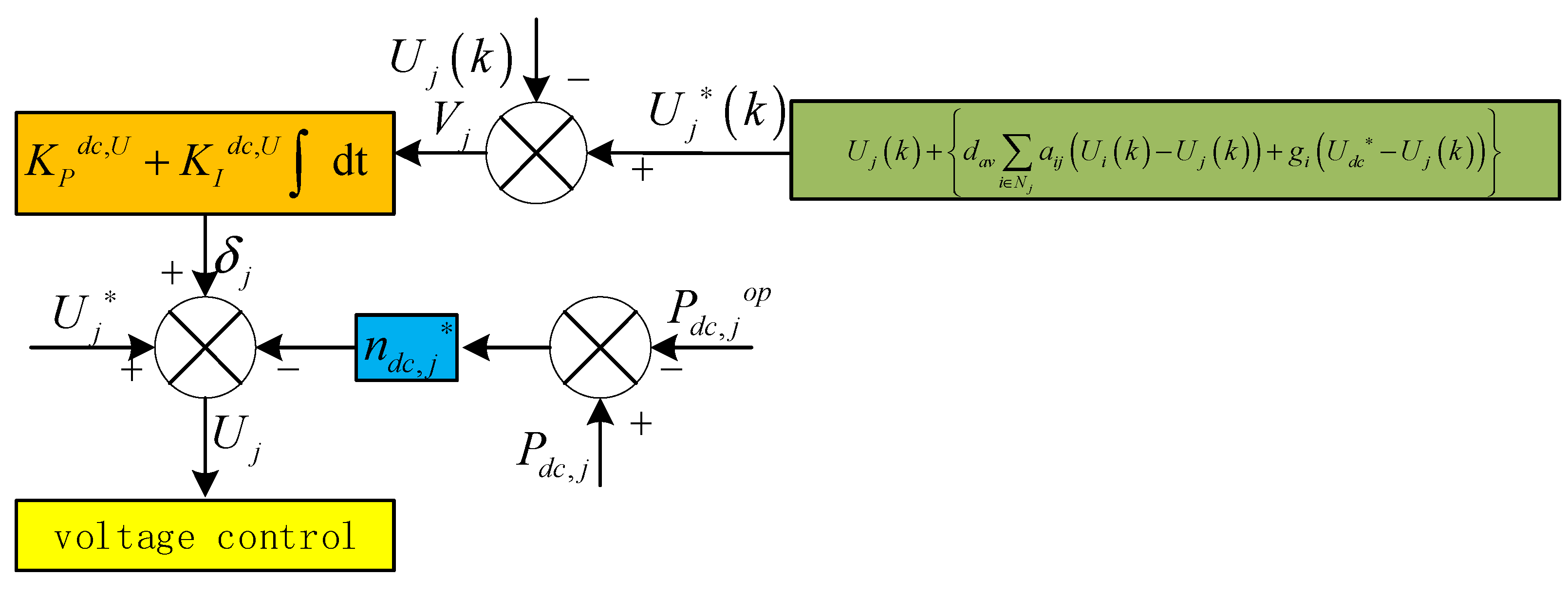
3.5. DC Subnet Control Strategy

The control target of DC subnet is the active power of each controllable distributed generation; the primary control is voltage droop control, and the secondary regulation mainly regulates voltage deviation and active power balance. The traditional u-p droop control of DC subnet is as follows:
U j = U j n d c , j ( P d c , j P d c , j )
where, U j , U j is the voltage and voltage reference value of the j-th distributed power supply, respectively; P d c , j , P d c , j are the active power and active power reference values of the jth distributed generation, respectively; n d c , j are the control coefficients corresponding to droop control, respectively.
The improved u-p droop control of its DC subnet is as follows:
U j = U j n d c , j ( P d c , j P d c , j o p ) + δ j
where, n d c , j are the control coefficients corresponding to droop control, respectively; P d c , j o p is the optimal power reference value of the jth DC subnet distributed generation δ j is the secondary adjustment item of voltage regulation. When U j U j , then P d c , j P d c , j o p ; since the active power of each distributed generation will tend to be the same at this time, the modest rise in the cost of distributed generation in each DC subnet will also tend to be the same, resulting in the DC subnet’s economic operation.
The secondary adjustment item of voltage δ j is as follows:
{ δ j = K P d c , U V j + K I d c , U V j d t V j = U j ( k ) U j U j ( k ) = U j ( k ) + { d a v i N j a i j ( U i ( k ) U j ( k ) ) + g i ( U d c U j ( k ) ) }
wherein, K P d c , U , K I d c , U are the scale factor and integral factor of voltage regulation, respectively; U j ( k ) , U j ( k ) is the voltage reference value obtained by discrete consistency principle and the voltage value at time k; d a v is the voltage mean convergence factor, which is used to represent the convergence space of voltage regulation; and U d c is the voltage reference value at the DC bus.
The voltage convergence of distributed generators is achieved via voltage secondary regulation management, as shown in Figure 4. However, because the u-p control mode is adopted, the regulation of voltage is actually the regulation of active power, so there will be a conflict between the two; at this time, the convergence factor dav of DC subnet can be adjusted to balance the relationship between the two. The active power distribution and voltage tracking of DC subnet may be implemented using an enhanced optimal power reference iterative technique based on discrete consistency. In addition, by taking into account the output of renewable energy and energy storage in active power distribution, the DC subnet can more reasonably fit the actual microgrid and realize the economic operation of DC subnet.

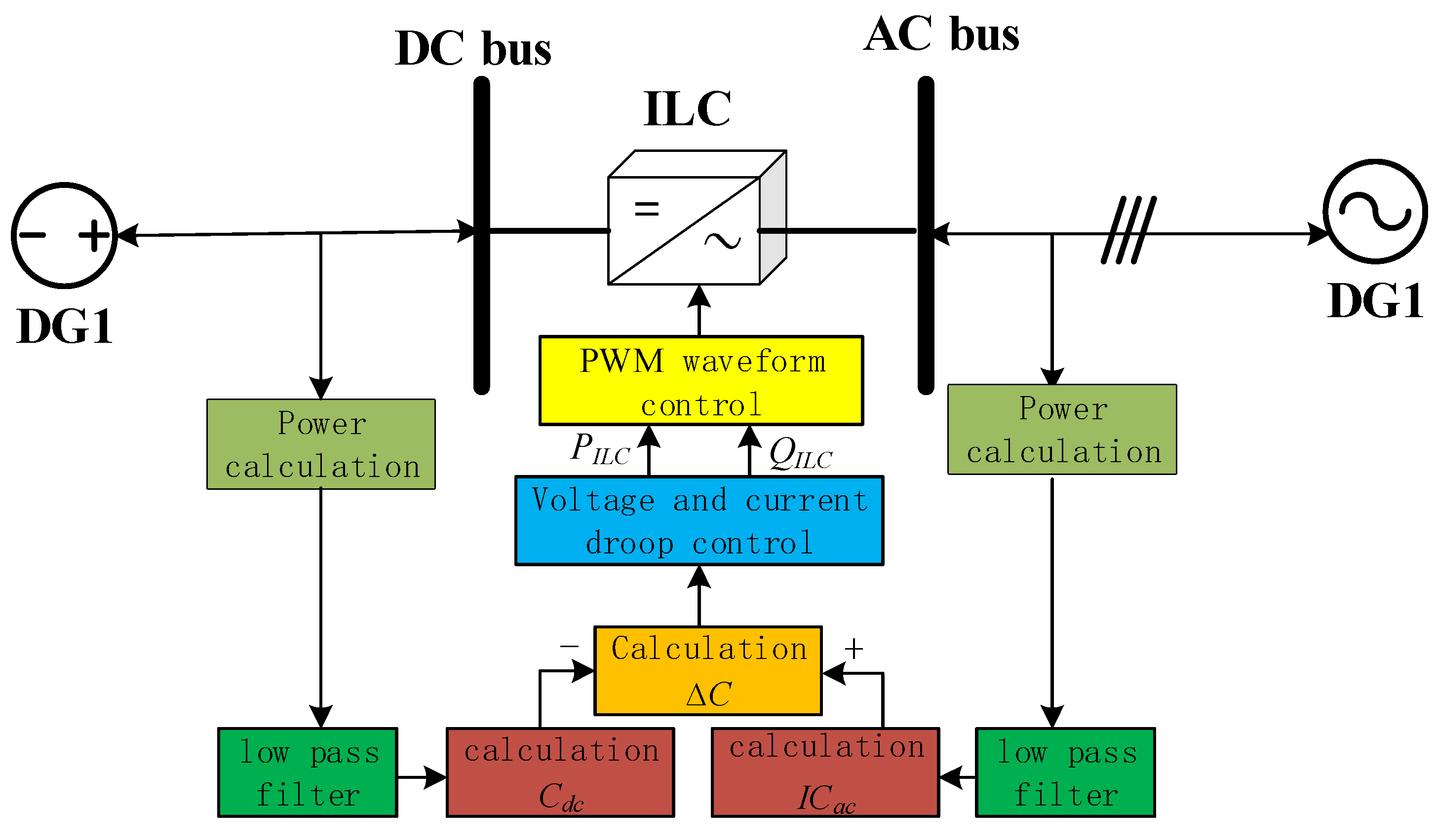
3.6. Microgrid Groups Control Strategy

Following the management of the control mode across subnets in the previous two sections, the microgrid subnet can have an appropriate distribution of active power to achieve stable operation. However, the cost increment of AC and DC subnets may be quite different, a control strategy between microgrid groups must be designed to ensure hybrid microgrid global stability.
The DC subnet and AC subnet are connected through a bidirectional interconnection converter (ILC). ILC can be used to exchange power between subnets, which is of great significance to maintain the voltage stability of DC subnet and the frequency stability of AC subnet. Therefore, in order to maintain the global economic operation and the stability of power exchange between subnets, it can be seen from the first two control modes that the DC subnet can realize DC bus voltage tracking, and the voltage and frequency of the AC subnet are asymptotically stable with the AC bus. As a result, traditional voltage and frequency-based inter subnet control is no longer required. The control technique of ILC between subnets based on cost micro increment is aimed to achieve cost micro increment consistency between subnets and steady global economy operation.
In order to achieve global autonomous economic operation and solve the problem of difference in cost increment between subnets, the switching power between subnets shall be scheduled. The scheduling model is as follows:
Δ I C = K P I L C ( I C a c I C d c ) + K I I L C ( I C a c I C d c ) d t
where, Δ I C is the difference of cost increment between DC subnet and AC subnet; K P I L C , K I I L C are the scale factor and integral factor of ILC exchange power, respectively; I C a c , I C d c is the cost micro increment of AC subnet and DC subnet, respectively. When there is more than one DC subnet and AC subnet, I C a c I C d c should be replaced by I C a c ¯ I C d c ¯ , I C a c ¯ , I C d c ¯ , respectively, mean the mean value of AC subnet cost increment and DC subnet cost increment. Considering that multiple AC subnets and DC subnets are interconnected, multiple interconnected converters will be used for connection. At this time, the mean value of cost micro increment should be the mean value of cost micro increment of several subnets connected only with an interconnected converter. Since the architecture set in this paper is the connection of a single DC subnet and AC subnet, the inter group control model between multiple subnets will not be expanded here. Therefore, the calculation Equation in ILC only considers that when an AC subnet and a DC subnet are connected in parallel, the control strategy between subnets does not consider the necessity of further balance due to the difference of cost increment of different subnets, that is, Δ I C is different. The control strategy between microgrid subnets set in this paper can be represented by the following Figure 5. After Δ I C is calculated by the Equation, the active power and reactive power of bidirectional interconnected converter can be obtained for voltage and current droop control between subnets, so as to generate PWM waveform and maintain power stability between subnets.
In the hierarchical control of microgrid, the response delay of distributed generation and sub microgrid may lead to the collapse of the whole control cycle, affecting the convergence and stability of the whole microgrid. Therefore, in order to deal with the impact of DG delay on the whole microgrid, the whole control cycle should be reasonably allocated. According to the literature, when the upper distributed control’s optimization bandwidth is less than the lower control’s, the upper control cycle has no effect on the overall control performance.
When configuring the distributed control cycle, the primary control within the subnet should define the minimum time scale, followed by the secondary control within the subnet, and finally the control strategy of ILC between subnets. The control time of droop control can be adjusted by adjusting the parameters of the scale factor and integral factor of droop control. On the premise that the control cycle is set to be consistent, the PI coefficient of the control strategy between the upper subnets should be much less than the lower control coefficient, and the PI coefficient of the secondary control in the subnets should be slightly greater than the ILC control coefficient between the subnets and less than the primary control coefficient. Finally, the control coefficient of primary control in the subnet is set to the minimum.

4. Case Analysis

Before the simulation, the operation parameters of DC microgrid are described. The cost coefficients of each distributed power supply in the figure are shown in the Table 1. Similar coefficient settings can be found in [21].
The Table 2 depicts the main parameters of the line.
The main control parameters of AC/DC hybrid microgrid control algorithm are shown in the Table 3.
In order to examine the advantages and disadvantages of the proposed algorithm based on discrete consistency, several comparative experiments are designed to validate the performance of the suggested optimal power reference iterative method based on discrete consistency in a microgrid.

4.1. AC Subnet Simulation Test

The AC sub network is tested. In the initial state of the sub network, only distributed generators 4 and 6 are connected to the power grid, the active load of the sub network is 80 kVA, the simulation time is set to 0.9 s, the distributed generator 5 is connected in 0.3 s, and the load is increased to 100 kVA in 0.6 s to test the power grid operation state of the microgrid under the current control mode. The incremental cost of AC subnet is shown in Figure 6.
According to the analysis of Figure 6a, each distributed power generation does not operate according to the cost increment, and it is not realized when the power grid conditions change at 0.3 s and 0.6 s. Referring to Figure 6b, in 0–0.3 s, since only distributed generators 4 and 6 are connected to the microgrid, the cost increment of distributed generators 4 and 6 is the same, and the value of distributed generator 5 is 0; At 0.3 s, the distributed generation 5 is put into operation, and the cost increment of the three distributed generators tends to be the same; in 0.6 s, the AC load increases by 20 kVA. At this time, the load power demand increases, the active power generated by the distributed generation increases, and the cost of the three distributed generation increases slightly.
At the same time, the frequency and voltage of the node where distributed generation is located are measured, respectively, in order to measure the impact of economic operation control on the voltage and frequency at the AC subnet side, and the measurement results are shown in Figure 7 and Figure 8.
Figure 7 shows the frequency values measured by the distributed power generation nodes of the AC subnet. When power grid conditions vary, as shown in Figure 7a, traditional droop control produces substantial fluctuations, and the power grid frequency does not achieve good tracking effect after stabilizing, and the power grid frequency is stable at 49.99 Hz. Following roughly 0.2 s after the test, the frequency of the AC subnet reaches a stable condition of 50 Hz, as shown in Figure 7b. After a brief fluctuation, the frequency returns to a steady condition after 0.3 s distributed power addition and 0.6 s load power rise, indicating that the frequency tracking of the AC subnet is effective.
Figure 8 depicts the node voltage measured by each distributed power node of the AC subnet. As shown in Figure 8, the voltage of each node in Figure 8a ultimately stabilized below 220V after the power grid fluctuation process, and did not achieve a good tracking effect. After a short process, the voltage of each node of the DC subnet attained a steady condition of 220 V, as shown in Figure 8b. When the 0.3 s distributed generation is added and the 0.6 s load power rises, the node voltage reaches a stable state again after a short fluctuation, indicating that the proposed algorithm has a satisfactory tracking effect on the AC subnet side.

4.2. DC Subnet Simulation Test

Examine the DC sub network. In the initial state of the sub network, the distributed power generation 1 and 3 are connected to the power grid. The active load of the sub network is 80 kVA, the simulation time is set to 0.9 s, the distributed power generation 2 is connected in 0.3 s, and the load is increased to 100 kVA in 0.6 s to test the power grid operation state of the microgrid under the current control mode. Figure 9 depicts the added cost of DC subnet distributed generating.
Figure 9 shows the cost increment change process for each distributed power node in the DC subnet. It can be seen from the figure that in the initial state, only distributed power generation 1 and 3 are connected to the microgrid, and distributed power generation 2 is disconnected. In Figure 9a, the cost increment of each node does not realize the allocation of active power according to the cost. Therefore, it can be seen that the distributed nodes cannot realize economic operation under the traditional droop control mode. In Figure 9b, after a short time change of each node, the cost increment of distributed generation 1 and 3 tends to be the same, and the value of node 2 is 0. When node 2 is connected to the microgrid in 0.3 s, each node distributes active power according to the cost, and the cost increment of the three nodes tends to be the same. With the increase of 0.6 s load power, the active power provided by each node will also increase, and the modest increase of node cost will increase slightly.
The voltage fluctuation diagram of each DC subnet node is shown in Figure 10. Figure 10a shows that under the traditional droop control mode, the DC node voltage did not achieve satisfying tracking effect, in which the node voltage of distributed nodes 1 and 2 was not stable at 300 V. After a short transition phase, the voltage achieves a stable state of 300 V in Figure 10b. When the 0.3 s distributed generation is added and the 0.6 s load power rises, the node voltage reaches a stable state again after a short fluctuation, indicating that the proposed algorithm has a satisfying tracking effect on the DC subnet side.

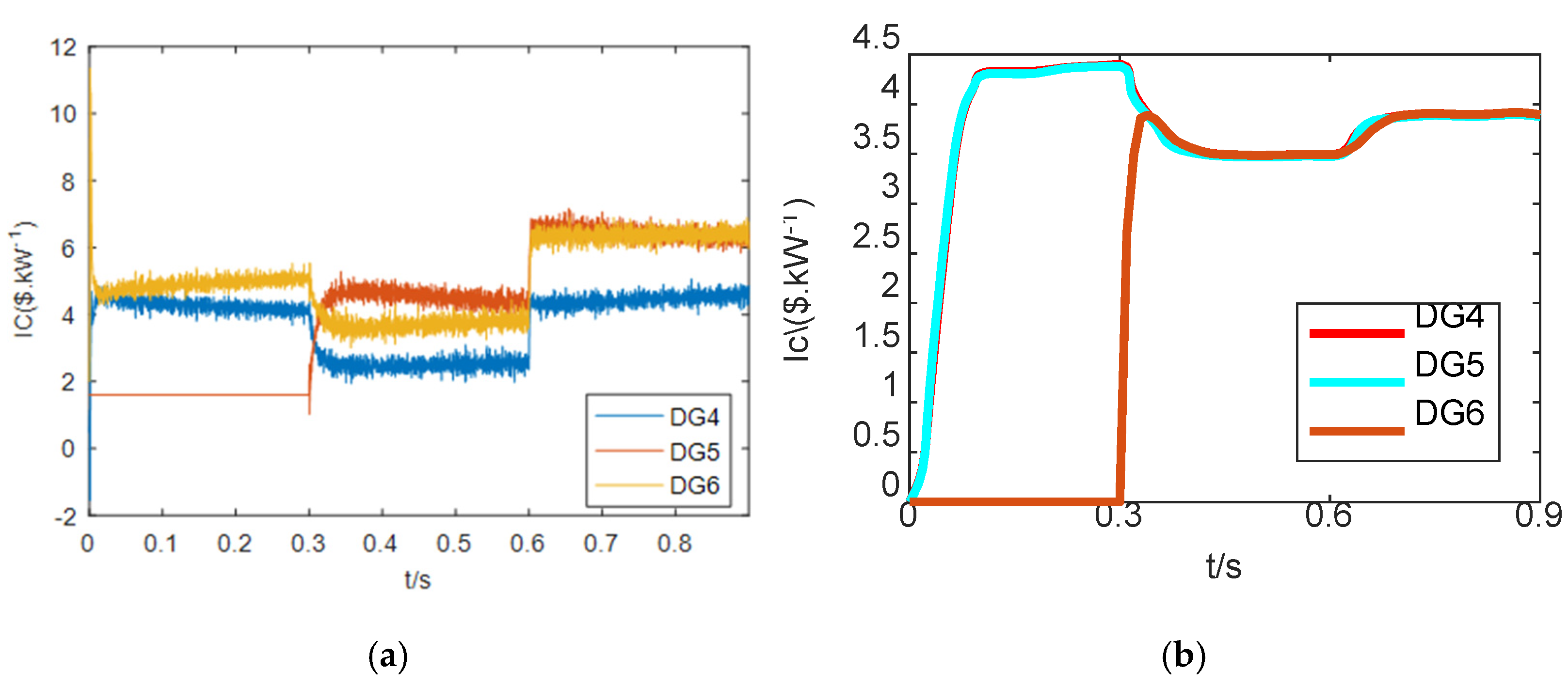
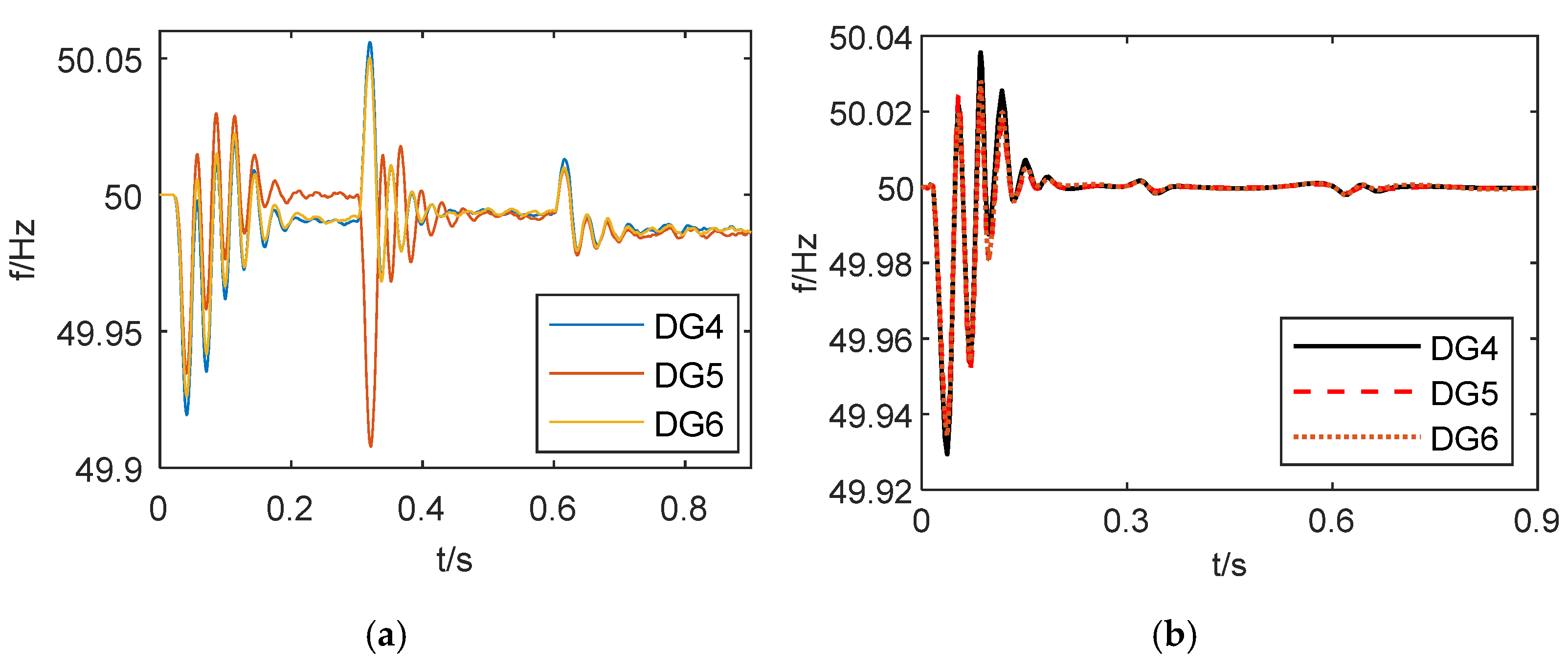
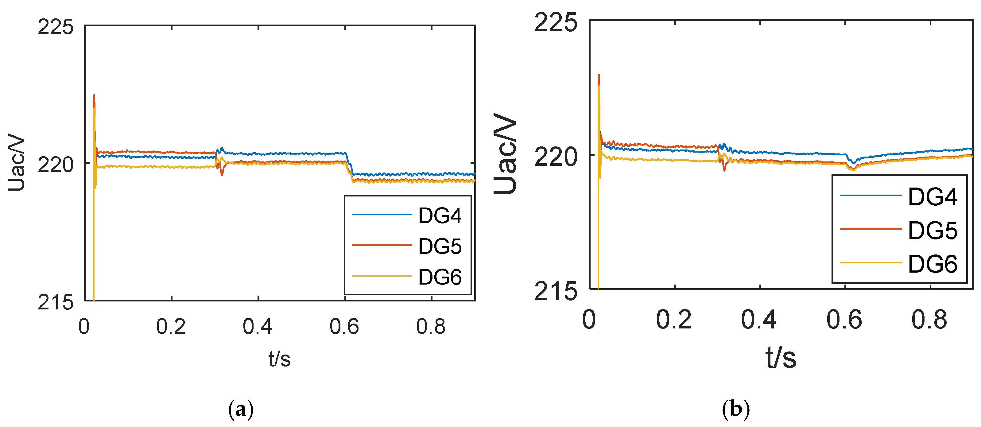
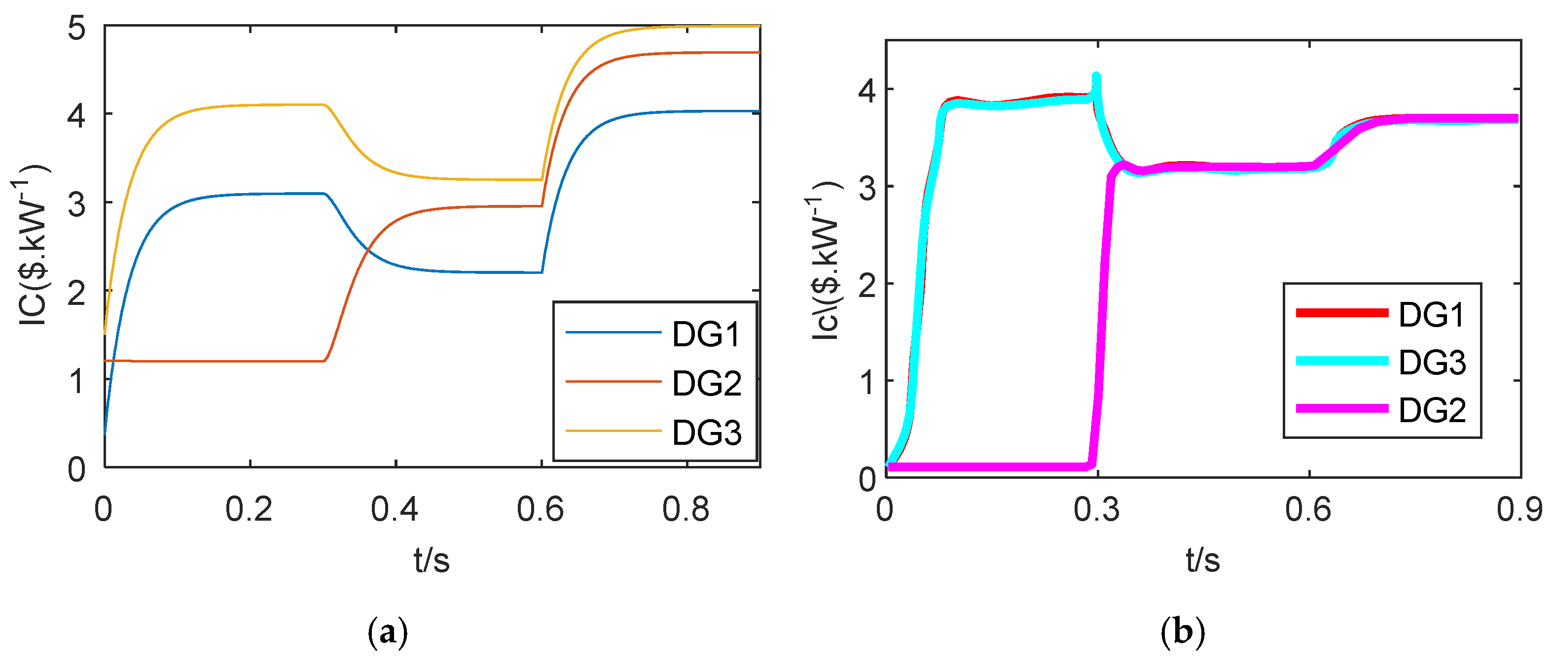
4.3. Microgrid Inter Group Control Test

In order to verify the effectiveness of hybrid microgrid, the operation status of distributed nodes of hybrid microgrid is tested after DC subnet and AC subnet are connected through interconnection converter. The simulation time for the microgrid is set at 1.5 s. In the initial state, all nodes except node 2 are connected to the microgrid; 0.3 s node 2 is connected to microgrid; 0.6 s DC load increased by 20 kVA; 0.9 s AC load increased by 20 kVA; 1.2 s distributed generation 6 cuts off the microgrid. The incremental cost of each distributed generation is obtained, as shown in Figure 5 and Figure 6.
Figure 11 shows the cost increment of each node in the overall system test environment. As shown in the above figure, in Figure 11a, each distributed node does not assign active power according to cost. In Figure 11b, since all nodes except node 2 are connected to the microgrid at the start, the cost increment of all nodes except node 2 is consistent after a short transition process, and the cost increment of node 2 is 0; 0.3 s, node 2 is connected to the microgrid, and each node redistributes active power according to the cost, and its cost increment is consistent. When the DC load increases for 0.6 s, the active power generated by the microgrid also needs to be increased synchronously. Under the action of the interconnected converter, each node of the microgrid on the DC and AC sides realizes the power distribution according to the cost coefficient, and the cost increment of the nodes on the DC side and AC side tends to be the same; 0.9 s, the AC load increases, the active load of microgrid increases, the generated active power also increases, and the slight increase of cost of each node tends to be the same; 1.2 s, the distributed generation 6 cuts off the microgrid, so that all nodes except node 6 distribute active power, so that the cost increment of other nodes tends to be the same. It can be seen that the inter group control of hybrid microgrid has good distribution effect in terms of economic operation.
In order to test the influence of interconnected converter control on DC subnet voltage and AC subnet frequency, the voltage fluctuation process on DC side and frequency fluctuation process on AC side are measured, respectively, as shown in Figure 12 and Figure 13.
Figure 12 shows the voltage fluctuation diagram of each node on the DC side once the connecting converter is operational, as shown in the above figure. Figure 12a shows how, after the power grid fluctuation process, each distributed node in the traditional droop control method reaches a stable state. Finally, the power grid’s tracking effect is poor, and distributed nodes 1 and 2 are unstable at 300 V. In Figure 12b, node 2 is not connected to the microgrid at the initial time, so the other voltages follow the grid reference value of 300 V, whereas the voltage of node 2 operates independently and is stable at 320 V, 0.3 s, node 2 access; 0.6 s, DC load increases; 0.9 s, the AC load increases, 1.2 s, the AC power is cut off. The voltage of each node of the DC subnet reaches a stable state after a short transition period, as shown in the diagram above. As can be shown, the inter group control method has no effect on the DC sub-voltage net’s stability.
Figure 13 shows the frequency fluctuation diagram of each node on the AC side after the interconnection converter is connected, as shown in the above figure. Figure 13a shows how the power grid fluctuates substantially when conditions change in the traditional droop control technique. Finally, the frequency tracking effect of AC subnet is not obvious. Figure 13b shows how, after a short transition process, the frequency reaches a steady state of 50 Hz. Under the overall operation conditions of microgrid, the changes of distributed generation and load at subsequent times do not affect the change of subnet frequency. It can be seen that the economic control strategy between microgrid groups does not affect the frequency stability of AC subnet.

5. Discussion

In this paper, an optimal power reference iterative algorithm based on cost increment is proposed for hybrid AC/DC microgrid to improve droop control and optimize the economy of power grid operation. Compared with the droop control under the microgrid double-layer control structure in literature, the secondary control is added to adjust the voltage and current fluctuations. At the same time, the entire influence of energy storage and renewable energy on the system is considered in literature, and lastly, the consideration of the overall system economy on the output of distributed generation is realized.
In the future, it can be considered to include a variety of economic consideration indicators such as bad environment in the economic cost, as well as the optimization index of reactive power and the economic cost optimization coefficient of renewable energy, all while taking into account the overall stability of the power grid, in order to achieve optimal operation over a wider range.

6. Conclusions

To address the problem that the operation control of hybrid AC/DC microgrid does not take the economic cost into account, a new distributed control method is proposed based on traditional droop control. Firstly, at the sub network level, the microgrid allocates active power according to cost, and realizes the stable operation. AC microgrid can realize bus voltage following and frequency stability, and DC microgrid can realize DC voltage stability. At the inter-subnet control level, the economic distribution of DC subnet and AC subnet is realized, as is the optimal scheduling between subnets, and the stability of microgrid operation. The proposed control approach in this research is applicable for microgrid economic stability control with additional internal combustion engine DG. Given the variety of DGs involved in power supply, it can be expanded to the cost-effective operation of several subnets.

Author Contributions

Conceptualization, W.L. and H.W.; methodology, H.Z.; software, Y.Y.; validation, W.L; formal analysis, H.Z.; investigation, H.W.; data curation, W.L.; writing—original draft preparation, W.L.; writing—review and editing, Y.Y.; supervision, H.W.; project ad-ministration, H.Z.; funding acquisition, Tianjin University of Technology (TJUT). These authors contributed equally to this work. All authors have read and agreed to the published version of the manuscript.

Funding

This research was funded by Key project of Tianjin Natural Science Foundation, grant number 08jczdjc18600 and Key fund project of Tianjin Education Commission, grant number 2006zd32.

Data Availability Statement

Cofficients of DG cost functions] Zheng, S. 2021. Web of Science; 10.1049/rpg2.12198.

Conflicts of Interest

The authors declare no conflict of interest. The funders had no role in the design of the study; in the collection, analyses, or interpretation of data; in the writing of the manuscript, or in the decision to publish the results.

References

  1. Karim, M.A.; Currie, J.; Lie, T.-T. A machine learning based optimized energy dispatching scheme for restoring a hybrid microgrid. Electr. Power Syst. Res. 2018, 155, 206–215. [Google Scholar] [CrossRef] [Green Version]
  2. Silva, D.P.E.; Félix Salles, J.L.; Fardin, J.F.; Pereira, M.M. Management of an island and grid-connected microgrid using hybrid economic model predictive control with weather data. Appl. Energy 2020, 278, 115581. [Google Scholar] [CrossRef]
  3. Li, X.; Dong, C.; Jiang, W.; Wu, X. Distributed control strategy for global economic operation and bus restorations in a hybrid AC/DC microgrid with interconnected subgrids. Int. J. Electr. Power Energy Syst. 2021, 131, 107032. [Google Scholar] [CrossRef]
  4. Battistelli, C.; Agalgaonkar, Y.P.; Pal, B.C. Probabilistic Dispatch of Remote Hybrid Microgrids Including Battery Storage and Load Management. IEEE Trans. Smart Grid 2017, 8, 1305–1317. [Google Scholar] [CrossRef]
  5. Mahmoodi, M.; Shamsi, P.; Fahimi, B. Economic Dispatch of a Hybrid Microgrid with Distributed Energy Storage. IEEE Trans. Smart Grid 2015, 6, 2607–2614. [Google Scholar] [CrossRef]
  6. Qiu, H.; Gu, W.; You, F. Bilayer Distributed Optimization for Robust Microgrid Dispatch with Coupled Individual-Collective Profits. IEEE Trans. Sustain. Energy 2021, 12, 1525–1538. [Google Scholar] [CrossRef]
  7. Sadighmanesh, A.; Sabahi, M.; Zavvari, M. Probabilistic dispatch in hybrid-microgrid system with considering energy arbitrage. J. Renew. Sustain. Energy 2019, 11, 25904. [Google Scholar] [CrossRef]
  8. Shi, R.; Li, S.; Sun, C.; Lee, K.Y. Adjustable Robust Optimization Algorithm for Residential Microgrid Multi-Dispatch Strategy with Consideration of Wind Power and Electric Vehicles. Energies 2018, 11, 2050. [Google Scholar] [CrossRef] [Green Version]
  9. Surender Reddy, S.; Park, J.Y.; Jung, C.M. Optimal operation of microgrid using hybrid differential evolution and harmony search algorithm. Front. Energy 2016, 10, 355–362. [Google Scholar] [CrossRef]
  10. Ramya, K.T.Y. Discretionary controller for hybrid energy storage system based on orderly control considering commercial value in decentralised microgrid operation. COMPEL—Int. J. Comput. Math. Electr. Electron. Eng. 2018, 37, 1969–1980. [Google Scholar]
  11. Wang, T.; He, X.; Deng, T. Neural networks for power management optimal strategy in hybrid microgrid. Neural Comput. Appl. 2017, 31, 2635–2647. [Google Scholar] [CrossRef]
  12. Wu, H.; Zhuang, H.; Zhang, W.; Ding, M. Optimal allocation of microgrid considering economic dispatch based on hybrid weighted bilevel planning method and algorithm improvement. Int. J. Electr. Power Energy Syst. 2016, 75, 28–37. [Google Scholar] [CrossRef]
  13. Jiang, K.; Wu, F.; Zong, X.; Shi, L.; Lin, K. Distributed Dynamic Economic Dispatch of an Isolated AC/DC Hybrid Microgrid Based on a Finite-Step Consensus Algorithm. Energies 2019, 12, 4637. [Google Scholar] [CrossRef] [Green Version]
  14. Zhang, Z.; Yue, D.; Dou, C.; Zhang, H. Multiagent System-Based Integrated Design of Security Control and Economic Dispatch for Interconnected Microgrid Systems. IEEE Trans. Syst. Man Cybern. Syst. 2021, 51, 2101–2112. [Google Scholar] [CrossRef]
  15. Jin, X.; Mu, Y.; Jia, H.; Wu, J.; Jiang, T.; Yu, X. Dynamic economic dispatch of a hybrid energy microgrid considering building based virtual energy storage system. Appl. Energy 2017, 194, 386–398. [Google Scholar] [CrossRef]
  16. Zhou, Q.; Shahidehpour, M.; Li, Z.; Xu, X. Two-Layer Control Scheme for Maintaining the Frequency and the Optimal Economic Operation of Hybrid AC/DC Microgrids. IEEE Trans. Power Syst. 2019, 34, 64–75. [Google Scholar] [CrossRef]
  17. Clarke, W.C.; Brear, M.J.; Manzie, C. Control of an isolated microgrid using hierarchical economic model predictive control. Appl. Energy 2020, 280, 115960. [Google Scholar] [CrossRef]
  18. Zhu, Y.; Wang, Z.; Liu, Y.; Wang, H.; Tai, N.; Jiang, X. Optimal Control of Microgrid Operation Based on Fuzzy Sliding Mode Droop Control. Energies 2019, 12, 3600. [Google Scholar] [CrossRef] [Green Version]
  19. Liu, Y.; Wang, X.; Wang, S. Research on Frequency Control of Islanded Microgrid with Multiple Distributed Power Sources. Processes 2020, 8, 193. [Google Scholar] [CrossRef] [Green Version]
  20. Zheng, S.; Liao, K.; Yang, J.; He, Z.; Sun, X. A novel bilayer coordinated control scheme for global autonomous economic operation of islanded hybrid AC/DC microgrids. IET Renew. Power Deneration 2021, 15, 2726–2739. [Google Scholar] [CrossRef]
  21. Zhou, Q.; Shahidehpour, M.; Li, Z.; Che, L.; Alabdulwahab, A.; Abusorrah, A. Compartmentalization Strategy for the Optimal Economic Operation of a Hybrid AC/DC Microgrid. IEEE Trans. Power Syst. 2020, 35, 1294–1304. [Google Scholar] [CrossRef]
Figure 1. Main structure of hybrid AC/DC microgrid.
Electronics 11 00013 g001
Figure 2. Distributed generation communication structure.
Electronics 11 00013 g002
Figure 3. AC subnet control block diagram.
Electronics 11 00013 g003
Figure 4. DC subnet control block diagram.
Electronics 11 00013 g004
Figure 5. Control structure diagram between hybrid microgrid groups.
Electronics 11 00013 g005
Figure 6. Distribution of AC subnet cost increment. (a) Cost increment distribution diagram of AC subnet with traditional droop control. (b) Cost increment distribution of AC subnet based on OPPRA.
Electronics 11 00013 g006
Figure 7. Frequency of each node of AC subnet. (a) Frequency of each node of AC subnet under traditional droop control. (b) Frequency of each node of AC subnet based on OPPRA.
Electronics 11 00013 g007
Figure 8. Voltage of each node of AC subnet. (a) Voltage of each node of AC subnet under traditional droop control. (b) Voltage of each node of AC subnet based on OPPRA.
Electronics 11 00013 g008
Figure 9. DC subnet cost micro increment. (a) Micro increment of each node cost of DC subnet under traditional droop control. (b) Cost micro increment of each node of DC subnet based on OPPRA.
Electronics 11 00013 g009
Figure 10. Voltage of each node of DC subnet. (a) Voltage of each node of DC subnet under traditional droop control. (b) Voltage of each node of DC subnet based on OPPRA.
Electronics 11 00013 g010
Figure 11. Distribution diagram of incremental cost of each distributed generation. (a) Cost increment of distributed nodes in hybrid microgrid under traditional droop control. (b) Cost micro increment of distributed nodes in hybrid microgrid based on OPPRA.
Electronics 11 00013 g011
Figure 12. DC side voltage fluctuation process. (a) Schematic diagram of voltage fluctuation of each node at DC side under traditional droop control mode. (b) Schematic diagram of voltage fluctuation at each node on DC side based onOPPRA.
Electronics 11 00013 g012
Figure 13. AC side power fluctuation process. (a) Schematic diagram of frequency fluctuation of each node at AC side under traditional droop control. (b) Schematic diagram of frequency fluctuation of each node at AC side based on OPPRA.
Electronics 11 00013 g013
Table 1. Distributed power cost coefficient.
SubnetDG i α i ( $ / K W 2 h ) β i ( $ / K W h ) ( $ / h )
AC SubnetDG14.60 × 10−21.20 × 10−20.25
DG24.20 × 10−20.6.0 × 10−20.27
DG33.60 × 10−23.80 × 10−20.32
DC SubnetDG15.60 × 10−25.60 × 10−20.21
DG24.80 × 10−24.50 × 10−20.36
DG33.20 × 10−24.80 × 10−20.20
Table 2. Main parameters of the line.
SubnetParameterSymbolsValues
AC SubnetRated power ω * 50 HZ
Line impedance R l i n e , L l i n e 0.5 Ω, 1.5 mH
AC DG capacity P i , m a x a c 15 KW
AC load Z a c 80 + j20 (kVA)
DC SubnetRated voltage U * 220 V
Line impedance R l i n e 1 Ω
DC DG capacity P i , m a x d c 15 KW
DC load Z d c 100 (kVA)
Table 3. Main control parameters of microgrid.
ParameterValues
m a c , i \ n a c , i 0.01/0.001
c a v \ d a v 0.2
K P ω \ K I ω 0.5/2.0
K P a c , U \ K I a c , U 0.1/2.0
n d c , j 0.01
K P d c , U \ K I d c , U 1/10
K P I L C \ K I I L C 0.005/0.2
m a c , i \ n a c , i 0.001/0.2
Publisher’s Note: MDPI stays neutral with regard to jurisdictional claims in published maps and institutional affiliations.

