Article

A Flexible Operation and Sizing of Battery Energy Storage System Based on Butterfly Optimization Algorithm

by
Basit Olakunle Alawode
1,
Umar Taiwo Salman
1,* and
Muhammad Khalid
1,2,3
1
Electrical Engineering Department, King Fahd University of Petroleum & Minerals, Dhahran 31261, Saudi Arabia
2
Center for Renewable Energy and Power Systems, King Fahd University of Petroleum and Minerals, Dhahran 31261, Saudi Arabia
3
K.A. CARE Energy Research & Innovation Center, Dhahran 31261, Saudi Arabia
*
Author to whom correspondence should be addressed.
Electronics 2022, 11(1), 109; https://doi.org/10.3390/electronics11010109
Submission received: 17 November 2021 / Revised: 18 December 2021 / Accepted: 20 December 2021 / Published: 30 December 2021

Abstract

:
There is a surge in the total energy demand of the world due to the increase in the world’s population and the ever-increasing human dependence on technology. Conventional non-renewable energy sources still contribute a larger amount to the total energy production. Due to their greenhouse gas emissions and environmental pollution, the substitution of these sources with renewable energy sources (RES) is desired. However, RES, such as wind energy, are uncertain, intermittent, and unpredictable. Hence, there is a need to optimize their usage when they are available. This can be carried out through a flexible operation of a microgrid system with the power grid to gradually reduce the contribution of the conventional sources in the power system using energy storage systems (ESS). To integrate the RES in a cost-effective approach, the ESS must be optimally sized and operated within its safe limitations. This study, therefore, presents a flexible method for the optimal sizing and operation of battery ESS (BESS) in a wind-penetrated microgrid system using the butterfly optimization (BO) algorithm. The BO algorithm was utilized for its simple and fast implementation and for its ability to obtain global optimization parameters. In the formulation of the optimization problem, the study considers the depth of discharge and life-cycle of the BESS. Simulation results for three different scenarios were studied, analyzed, and compared. The resulting optimized BESS connected scenario yielded the most cost-effective strategy among all scenarios considered.

1. Introduction

Owing to the need for a reliable, clean, cheap, and large amount of electric power, microgrids have grown to be very popular. Nations are making policies that ensure not only the continuous supply of electricity but also electricity generation that is clean and healthy for the environment [1]. Microgrids have found themselves to be an integral part of many interconnected power systems. Having grown from small to large sizes, they seem to be the most promising future for the world’s need for clean energy. The microgrid can operate in off-grid (island) mode or grid-connected (anti-island) mode [2]. Due to the variability and intermittency of RESs, the island operation of the microgrid could be very challenging, as it is difficult to keep it operating smoothly for a long time without external support [3]. Usually, some features of the microgrid make it work efficiently under a constantly varying load. These features include distributed generators, storage systems, and a dumped load, which is a controllable load [4].
The microgrid can be supported with ESS to enhance its smooth operation. Nevertheless, the grid-connected microgrid receives support from the grid when fluctuations from the RES or variation from loads occur. These are some of the attributes that differentiate microgrids from centralized systems. Furthermore, the cost of maintenance and cost of operation in a centralized system is expensive when compared with that of the microgrid system because these costs are small in microgrid systems. Another advantage of microgrids over the centralized systems is the lower cost of setting up. Additionally, the microgrid systems produce cleaner energy, quality, and more reliable power than the centralized system when adequately controlled. The use of microgrid systems to produce cleaner power sources necessitates the use of ESS for its operation. Therefore, we are motivated to propose an efficient way to determine the optimal size of the battery energy storage system (BESS), which is the type of ESS considered in this study. Furthermore, we considered the life span and depth of discharge of the BESS in the formulation of the optimization problem, and the problem is solved using the BO algorithm.
As a case study, the proposed method is tested using the hourly load demand and wind power of a typical small residential area with a peak load of approximately 163 kW. By comparing the results of the three different scenarios of the study, we observed that the proposed methodology is reliable and gives the optimal solution. It searches for all possible solutions to find the optimal size of the BESS. Thus, it is able to minimize the overall operation cost of the microgrid.
The capacity optimization of BESS has been copiously addressed in the literature; however, gaps are still opened for the improvement of battery life under a highly varying wind-penetrated microgrid, since the battery operation under this condition is much more intermittent and requires more flexibility compared to its operation with other RES or under ordinary conditions. There is a need to investigate the size and life of the battery for its healthy operation. Moreover, we propose the butterfly algorithm, which has only been reported in few similar problems in the previous studies. We used the BO algorithm to evaluate the impact of wind power on battery operation, considering the depth of the dispatch of discharge (DOD) and the lifespan of the BESS under carefully selected scenarios. The strategies and the approach adopted would be helpful in the future study relating to wind-battery microgrid systems.
The rest of the paper is organized as follows. Various works related to this paper are discussed in Section 2. The problem formulation is discussed in Section 3, and the proposed methodology and all optimization constraints are explained in Section 4. The BO optimization algorithm is presented in Section 5, whereas Section 6 and Section 7 are dedicated to results and discussions followed by conclusions, respectively.

2. Related Work

Although the RESs are free and available almost everywhere, they require a considerable investment cost to be converted to electrical energy. The investment cost is dependent on the location and size of the distribution system. Various strategies for integrating the RESs in microgrids have been discussed in [5,6,7,8]. In [9], the authors present a survey of the planning of distributed generation in distribution systems, where they reviewed the effects of the system operating characteristics and conditions of DG systems, such as their reliability, stability, electric losses, and voltage profile. Reference [10,11] described different types of energy storage technologies and their applications. Although a number of them have been developed and commercially available, many are still under research and have received research support recently. ESS differ in the rate of charge and rate of discharge [12], energy capacity, and power capacity [13,14]. Consequently, storage technologies differ in size and weight. Figure 1 describes the characteristics of different ESS technologies [15]. The figure shows that BESS, such as lithium-ion, nickel–cadmium, lead–acid, etc, have higher energy capacities and a medium power rating. The power rating of the lithium-ion battery is in the range of 10 kW–100 kW, and that of Ni-Cd can be as high as 1.5 MW. Li-ion and Ni-Cd have commonly been used in RE power integration [16,17].
The ESS can be placed at any point on the grid depending on the configuration employed and the purpose for which they are deployed. For example, the ESS can perform the job of load leveling and peak shaving to support the peak demand [11]. Under such conditions, the ESS act as a load. The ESS can also help to attenuate any fluctuation in frequency and voltage magnitude, which consequently helps to improve the power quality of the renewable generators, as used in the microgrids. As an indispensable component of a microgrid, they can support the islanded operation mode by providing an uninterruptible means of power supply in the form of an uninterruptible power supply (UPS) to renewable generation sources, such as PV and wind power generation. Furthermore, when the cost of grid electricity is low, the ESS can store electricity from the utility, which is sold to customers at periods of high prices. This provides a good economical benefit for the microgrid operators. Additionally, the ESS can help to stabilize the voltage and frequency level of the microgrid following load disturbances, thus helping to improve the power quality of the grid [3].
To find the optimal size of a BESS, many strategies have been proposed in the literature. The formulation of problems involving BESS sizing usually follow a similar approach, as it usually includes the demand, BESS, and all power sources. However the optimization problems are usually formulated as cost minimization or profit maximization, which can be solved using classical optimization methods or metaheuristic optimization methods, such as the particle swarm optimization (PSO), genetic algorithm (GA), and grey-wolf optimization (GWO) [18,19], and new approaches, such as the whale optimization algorithm (WOA), firefly optimization (FFO), and Cayote optimization algorithm (COA), are reported in [20,21,22]. Yuan et al., [20] presented a study for the sizing and allocation of BESS by minimizing the loss in the distribution in a distribution network using the new COA. The study compared the COA with optimization algorithms, such as the whale optimization algorithm, firefly optimization algorithm, and PSO, and found that the COA produced efficient results. A similar approach was presented in [22], but used a whale optimization algorithm to reduce power losses in the distribution network. The optimal size of BESS is computed in [21] in a stand-alone microgrid using the convex optimization method, and the effectiveness of the method was demonstrated by a comparison with PSO and GA.
A two-level sizing of grid-scale BESS is proposed in [23], considering the effect of the uncertainty of wind power in the operation of the BESS. The proposed strategy involved lower level and upper level operations. The lower level operation introduced the battery’s cycle life model in the processing simulation of the battery for long-term operation. The upper level utilizes a marginal economic utility analysis and BESS reforming in the optimal sizing of the BESS. The study developed an iterative sizing algorithm designed to investigate the cycle of the battery after each round of an hour chronological operation. The cycle life of the battery is then corrected, after which, marginal analysis is performed on the power capacity and energy capacity of the battery based on double shadow prices. The results shows that the proposed technique is effective in the estimation of the cycle life of the battery under wind power uncertainties.
In [5], the authors investigated the optimal integration of RES with BESS in microgrids. The application of RES and BESS in the microgrid operation was discussed in [6,24]. In [25], the authors proposed the possibility of generating 100 MW from wind farms in four cities, including Dhahran, Riyadh, Jeddah, Nejran, and Guriat. The study, however, recommends hybrid technology to support the wind power of these cities.
In [26], the authors used a Markov chain to illustrate the fluctuation of wind power, and this fluctuation is measured by the variance of the grid power. The study suggested that the DP and Markov decision process are not suitable for tackling the dynamic problem of BESS because the variance measurement is non-additive but quadratic. The study developed an iterative optimization algorithm to derive a function that would address the mentioned problem. The derived difference formula’s efficiency is similar to the policy iteration in the Markov decision. Furthermore, the study presents a divide-and-conquer method that is much faster than the Markov chain method. Based on these techniques, the study evaluates the type, selection and capacity of BESS, which can enhance industrial guidance for the design of BESS, thereby minimizing the long-term fluctuation of RE and improving the stability of microg
Salman et al., presented a similar study in [27] for a wind-penetrated microgrid using the nonlinear optimization for both grid-connected and stand-alone microgrids. The optimal size of the battery and energy scheduling of an isolated microgrid was investigated in [28] using the firefly optimization algorithm. Furthermore, the optimal BESS for grid-connected microgrids subject to wind uncertainties has been investigated in [29] using stochastic programming.
Although the sizing and operation of BESS in a wind-penetrated microgrid have been tremendously studied in the literature, only few of the previous studies have used the BO algorithm to solve the optimization problem. Specifically, based on the limitations cited in [23,26], we present the BOA as another flexible solution for solving the problem of BESS wind power integration in the microgrid. Moreover, the contributions to study in this work are summarised as follows:
(1)
The proposed strategy in this study evaluates the impact of wind power operation on the DOD and cycle life of the BESS under specifically selected scenarios;
(2)
The study investigates the impact of wind power fluctuations in different locations and seasons of the year on the operation of the BESS;
(3)
It adopts the method of the capacity incremental strategy to size the BESS until the optimal capacity is reached and the effect of each incremental size is observed on the DOD of the BESS. This strategy shows the flexibility limit allowed within the microgrid distribution generation to achieve an economic operation;
(4)
Finally, this paper introduces the use of BOA for solving the optimization problem as a promising approach for the integration of BESS in a wind-penetrated microgrid.

3. Problem Formulation

In this section, the formulation of the problem is discussed and the modeling of the individual microgrid components is described.
In formulating the problem in this study, we consider a microgrid configuration of the type displayed in Figure 2. The microgrid is configured such that it can switch its operation between BESS connected mode and BESS disconnected mode. The wind power, which is the only RES, and three diesel generators are connected through the generator bus to the AC bus. Furthermore, the residential demand is connected through the load bus to the AC bus. There is also a dump load connected to the load bus that consumes the excess power after the demand is met and the BESS is fully charged. This prevents the BESS from being overcharged or the network lines from being overstretched. The BESS is connected directly through the switch to the AC bus. It is assumed that the battery has its converter and switching controller within the BESS module, and so the operation of the converter topologies and their control is beyond the scope of this study.
To investigate the objectives of this study, the strategies adopted are summarized into three operating scenarios as follows:
  • Scenario 1: BESS disconnected mode, where the microgrid is operated without the BESS;
  • Scenario 2: BESS connected mode, with a constant battery capacity of 100 kWh;
  • Scenario 3: BESS connected mode with an optimized battery capacity.

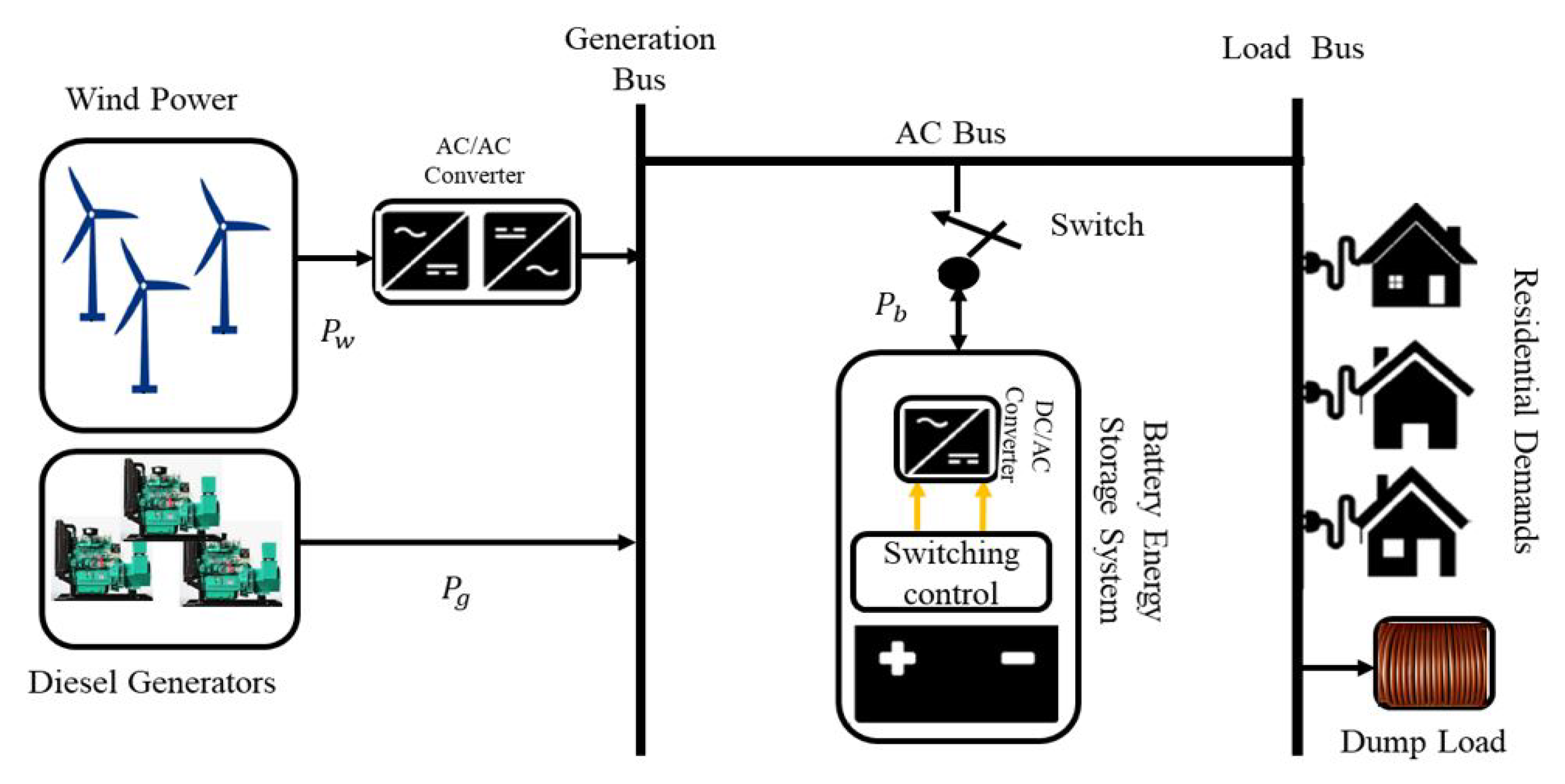
3.1. Wind Power Model

The power of a wind turbine is given by (1) [27]. The wind power model equation relates the output hourly power to the speed of the wind.
P w , t = 0 v t v C I or v t v C O P w m a x v t v C I v R v C I v C I v t v R P w m a x v R v t v C O
where v t is the wind speed at time t, v C I is the cut-in wind speed, v C O is the cut-out wind speed, v R is the rated wind speed, and P w m a x is the rated power of the wind plant.
The total cost of the dissipated power by the wind power plant for period T is given by (3) [28].
C R F = 1 365 × i r ( 1 + i r ) l y ( 1 + i r ) l y 1
C w ( t ) = t = 1 T P w , t I C w C R F
where I C w is the initial wind plant cost and CRF is known as the capital recovery factor, which is given by (2), with i r and l y referred to as the interest rate and projected battery lifetime of the wind power plant, respectively.

3.2. Generator Model

For a generator, i, the cost at a particular time, t, is given in terms of its dispatch power as (4) [30]. This assumes that we are using a diesel generator and that it serves as our secondary power generation source for the microgrid. The primary power source is wind power.
C g ( t ) = i = 1 N a i P g , i 2 ( t ) + b i P g , i ( t ) + c i
where P g , i ( t ) is the output power of generator i at time t. a i , b i , and c i are the coefficient of the ith generator. N is the number of generators considered.

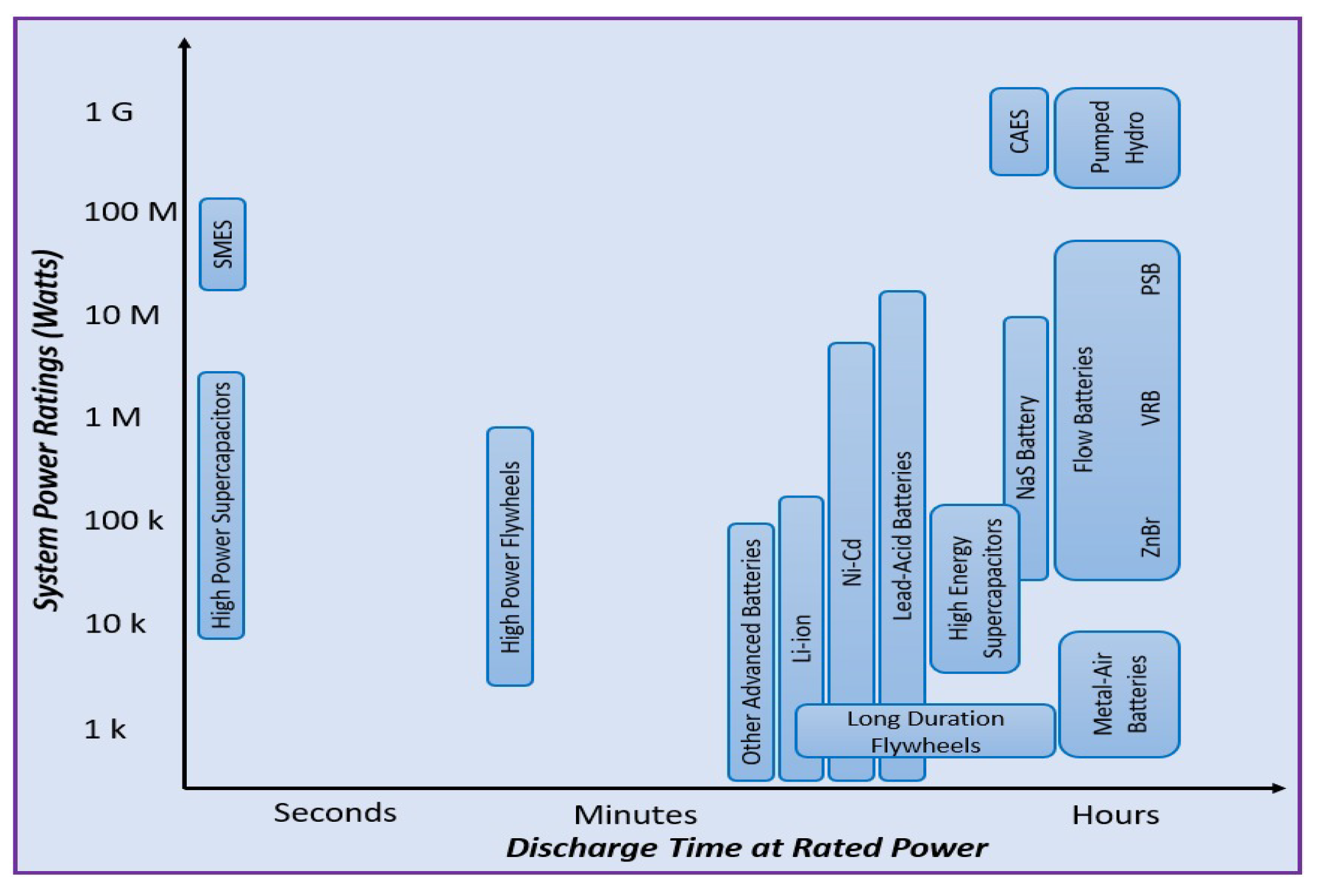
3.3. Battery Energy Storage Model

The BESS is considered as one of the most popular ESSs due to its wide availability and technology maturity [31]. The selection of a BESS type depends mostly on the application, as each technology has its power and energy characteristics, with the lithium-ion battery being one of the most efficient for storing wind and solar energy due to its long life, high efficiency, and high energy density [32]; thus, it has been selected for this study.
The analysis of the cost of BESS has been shown to depend on the life-cycle of the battery [27,28]. The life-cycle is dependent on the depth of discharge (DOD) of the battery [33]. Consequently, the cost of the BESS is also dependent on DOD. The battery DOD ( D O D b ( t ) ), life-cycle for a given DOD ( l ( t ) ), and the battery cost ( C b ) are given in the equations shown in (5).
D O D b ( t ) = 1 S O C b ( t )
l ( t ) = 694 ( D O D b ( t ) ) 0.795
C b ( t ) = C b , c a p P b ( t ) E s t o l ( t ) η b 2
where C b , c a p is the initial battery capacity cost. These equations also assume that the unit optimization time ( Δ t) is 1 h.

4. Proposed Methodology

In this section, the proposed sizing methodology for the problem is discussed. Furthermore, the objective function and all associated constraints are explained in this section.

4.1. The Objective Function

Having described the cost of the individual units making up the microgrid in the preceding sections, the total cost is, therefore, the sum of the costs of the wind plant ( C w ), the generator ( C g ), and the BESS ( C b ). Hence, the objective function for the optimal sizing problem is given in (6) as follows. The task is to minimize this objective function. The minimization of this cost function will yield the optimal size of the BESS.
J = m i n t = 1 T C w ( t ) + C g ( t ) + C b ( t )
where C w , C g , and C b are as previously defined and T is the total operation period, which is 24 h in this study.

4.2. Constraints

Minimizing the objective function comes with a set of constraints. The optimization must be carried out subject to the following constraints:

4.2.1. Power Balance Constraint

The power balance constraint in a power system is the primary constraint. This constraint ensures that the principle of demand and supply of power is maintained. It is given in (7).
P w ( t ) + P b ( t ) + i = 1 N P g ( t ) P L ( t ) = 0
where P L ( t ) is the power demanded by the load at time t.

4.2.2. Generator Constraint

At any time instant t, the output power of any generator i must be bounded by its minimum and maximum power limits. This limit is expressed by (8):
P g ( i ) m i n P g ( i , t ) P g ( i ) m a x i = 1 , 2 , , N

4.2.3. BESS Constraint

The constraints related to the BESS are expressed by Equations (9)–(13). In this work, we have chosen a positive and negative power convention for the discharging and charging powers of the battery. This means that the battery acts as a load when it is charging and as a generator when it is discharging. The optimization time interval, Δ t , is taken as 1 h. At any instance, the power withdrawn from the battery must be within acceptable limits of the battery; this condition is formulated in (9). Furthermore, the discharging and charging constraints of the battery are expressed in (10) and (11), respectively. The μ b is a binary variable that states the operating status of the battery. It is equal to 1 when the battery discharges and 0 when it charges. This variable prevents the charging and discharging of the battery at the same time.
Furthermore, the energy of the battery at any time instance must be within the limit allowed for the battery. This is captured in the constraint expressed in (12). The charging and discharging of the energy of the battery, which is dependent on the charging and discharging power, is given by (13) [34].
P b m i n P b ( t ) P b m a x
0 P b , d c h ( t ) P b μ b
P b ( 1 μ b ) P b , c h ( t ) 0
E b m i n E b ( t ) E b m a x
E b ( t + 1 ) = E b ( t ) P b , d c h Δ t η b , d c h ( P b ( t ) > 0 ) E b ( t ) P b , c h ( t ) Δ t η b , c h ( P b ( t ) < 0 )
where P b m i n and P b m a x are the minimum and maximum power that can be drawn from the BESS at any time t. Similarly, E b m i n and E b m a x refer to the minimum and maximum energy limits of the BESS at any time t. P b , c h ( t ) and P b , d c h ( t ) are the charging and discharging powers at time t. P b ( t ) and E b ( t ) are the battery power and energy at that time instance t.
Equation (13) also expresses state of charge ( S O C ) of the battery at any time t is dependent on the previous S O C and depends on the charging and discharging efficiencies, as well as the charging and discharging powers.

4.2.4. Proposed Optimization Procedure

Depending on the load demand, our proposed method utilizes the BO algorithm for the power balancing strategy at every hour in order to obtain the optimal battery size. Whenever the wind power is lesser than that of the demand, the algorithm dispatches powers from the generators and/or the BESS. However, this is based on the DOD of the battery, which ultimately affects the operational cost.
Depending on the cost equations of the power sources and the load demand at a particular hour, the proposed algorithm dispatches an optimal power from the energy sources and power generators. Whenever the cost of the BESS is higher than that of the generator, the algorithm also allows for the generators to charge the battery. This implies that the DOD of the battery is high at this instance. The battery SOC is computed every hour, at which time, the algorithm takes a decision on whether to charge or discharge the battery. The defined power resource scheduling strategy, which will minimize the overall cost of the microgrid, is obtained for the optimal battery size. The range of the battery size is taken from 100 to 300 kWh. With this understanding, we next discuss how optimization is performed using the BO algorithm.

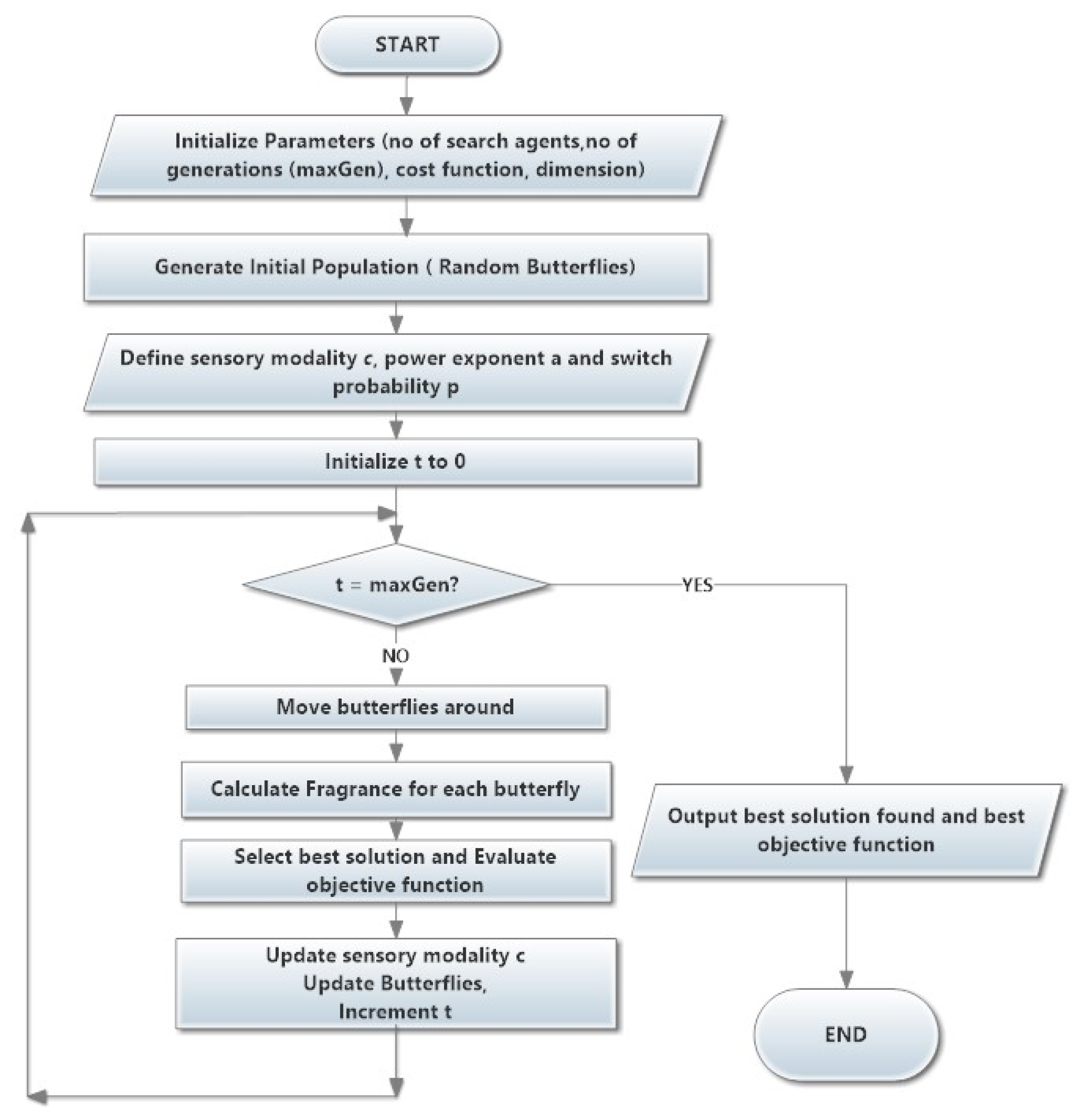
5. Butterfly Optimization Algorithm

This section discusses the parameters and the implementation of the BO algorithm as used in this study. The cost optimization that yields the optimal battery size is to be performed using the BO algorithm. The BO algorithm was proposed in [35] and has proven to be efficient for global optimization. The algorithm is a population-based algorithm like many other meta-heuristic algorithms, such as GWO, PSO, GA, etc. [36]. However, unlike the other algorithms, it has the advantage of a faster convergence. It is based on the movement of butterflies to attract one another. The algorithm is briefly described as follows:

5.1. Butterfly

It was observed that butterflies have an extremely precise feeling of finding the wellspring of scent. A butterfly’s power is created, and is related to its wellness. The butterfly then creates an aroma that is proportional to the created power. This implies that the power of a butterfly fluctuates as it moves from one place to another. Different butterflies can then sense the aroma as the butterflies moves. If a butterfly can detect the aroma, it will advance toward it; otherwise, it will move haphazardly in search of an aroma.

5.2. Fragrance

The fundamental property that distinguishes BOA from the other meta-heuristic algorithms is the butterfly aroma. Every aroma has its dedicated fragrance, such that each fragrance has its specific individual contact for every butterfly. The fragrance f is proportional to the stimulus intensity (I) and power exponent (a). The proportionality constant is the butterflies sensory modality (c). The fragrance f is therefore given by the expression in (14). In most cases, c and a are in the range [ 0 , 1 ] .
f = c × I a

5.3. Movement of Butterflies

Optimization using BOA is dependent on the movement of the butterflies in search of the global minimum. This is carried out in three steps as follows:
(a)
All butterflies can detect the presence of other butterflies due to the emission of some fragrance by all the butterflies;
(b)
All butterflies have two patterns of movement: (1) towards the butterfly emitting the best fragrance or (2) moving randomly;
(c)
The landscape of the objective function determines the stimulus intensities of the butterflies.

5.4. Generalized BO Algorithm

The generalized flowchart of the BO algorithm is as shown in Figure 3. BOA optimization is performed in three phases: (1) the initialization phase, (2) the iteration phase, and (3) the final phase. In the initialization phase, the objective function and the solution space (taking note of all constraints) are defined. The values of the BOA hyper-parameters are also defined in this phase. This is immediately followed by the creation of the initial population of butterflies by the algorithm. This population is used for optimization. The population size of the butterflies remains unchanged throughout the optimization process. This results in a fixed memory size allocation to store their information. The fragrance and objective (fitness) values are then used to update the position of the butterflies in the search space.
The second phase defines the iteration phase where the optimization is performed. For each iteration t, the fitness of all of the butterflies is calculated. This fitness is based on the new positions of the butterflies obtained in the previous iteration. This is then used to generate fragrances at their positions using (14). There are two search phases—(1) the global search and (2) the local search phase. In the global search phase, the butterfly moves towards the butterfly/solution g with the best (fittest) solution using (15), whereas, in the local search, the butterfly moves randomly in search of other butterflies close to its position using (16).
x i t + 1 = x i t + ( r 2 × g x i t ) × f i
x i t + 1 = x i t + ( r 2 × x j t x k t ) × f i
where x i t is the solution vector for the i th butterfly in iteration number t. The current best solution is denoted by g . The fragrance of the i th butterfly is represented by f i , and r is a random number in [ 0 , 1 ] . The j th and k th butterflies from the overall solution space are denoted by x j t and x k t , respectively.
After each iteration, i.e., butterfly movement, the butterfly with the best objective function is then selected. Based on the new objective function, the sensory modality c of each butterfly is updated. This cycle continues until the stopping criteria are met. Such criteria could be the amount of CPU time utilized, the maximum number of cycles achieved, the maximum number of iterations without any fitness improvement, a specified error range, or some pre-specified number of iterations. The commonly used stopping criteria is a pre-specified number of iterations. We also intend to use this in this paper. At the final stage, all calculations are carried out and the butterfly that achieved the minimal cost function is selected.
The BOA initiates a search process to determine the optimal power dispatch of the power of the microgrid that would guarantee that a safe operation of the BESS at the same time ensures that all of the system constraints are not compromised within possible limits. This procedure is repeated every time the capacity is increased at the incremental rate until the optimal capacity is reached and an optimal dispatch is achieved. Due to its robustness, the BO algorithm has been applied to several optimization problems, such as to optimize the parameters of a lead-lag controller for an improved stability performance [37].
A streamlined version of the algorithm called a dynamic BO algorithm (DBOA) was also used to perform feature selection problems [38]. The performance of the BOA surpasses that of the PSO. In addition, the BOA has a faster speed of convergence to the optimal solution than the PSO. The performance of the BOA was shown to supersede the performance of the PSO in [39,40]. In particular, the study in [41] justified the applicability of the BOA to an optimal dispatch problem such as ours, and it was proven that the BOA is more efficient than both the PSO and the GA. Consequently, we believe that the BOA can provide the desired efficient optimal solution.
The simulation in this study is carried out using the MATLAB simulation package running on a Windows 10 Intel core i7 16G RAM PC.

6. Simulation Results and Discussion

To illustrate the performance of the proposed method, we present a low voltage microgrid with three diesel generators and a Li-ion battery. Furthermore, we use a wind RES of 150 kW capacity. The diesel generators data, presented in Table 1 and the BESS data, such as its capital cost, maintenance cost, lifetime, and interest rate, presented in Table 2, have been taken from [28].
In Figure 4, we present a typical load profile of a residential area alongside the wind power profile used to test the proposed strategy in this work. From Figure 4, we can observe that, for most of the 24 h, the demand is greater than the power supplied by the RES. At these periods, the generators and the BESS supply the remaining powers needed to meet the demand. However, for very few periods, when the RES supply is greater than the demand, the excess powers are used to charge the BESS. To maintain the SOC of the BESS at an appreciable level for smooth and efficient running, the generators can be used to charge the BESS when needed; for instance, when the cost of discharging the BESS is greater than the cost of operating the generators. This condition occurs after the continued use of the BESS results in the depletion of the SOC of the BESS, thereby raising its discharge cost. Therefore, the BESS must operate at an optimal SOC, so that the state of health of the BESS is preserved and its lifespan is increased.
The results of the three scenarios considered are explained in the following subsections.

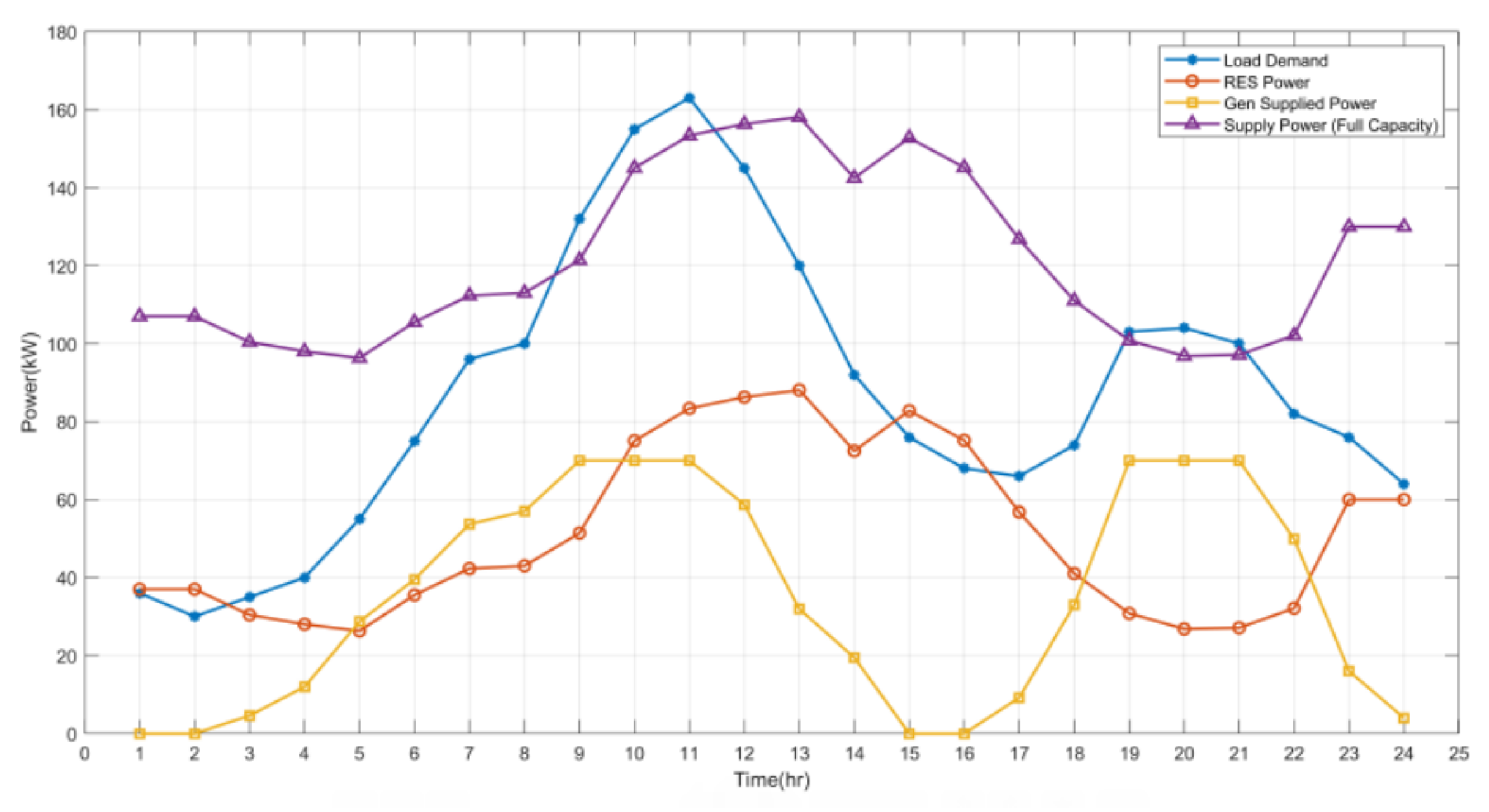
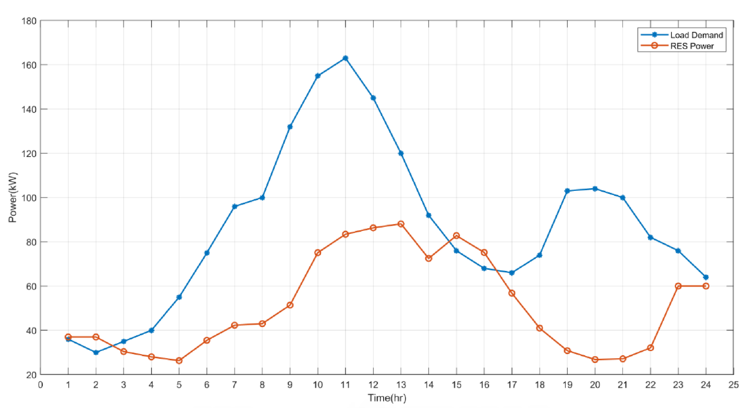
6.1. Scenario 1: BESS Disconnected Mode

In this scenario, the microgrid is operated without the BESS. As such, there will be no cost for the BESS. The only sources of the power supply are the RES and the generators. These sources have to be able to cater to the load demand at all times in order to not have load shedding; that is, there must be no mismatch at all times. Figure 5 shows the load demand and the supply from the RES and the generators for all times. The figure also provides the supply power when our generators operate at full capacity. It can be observed that, at some hours, the installed capacity cannot meet up with the demand, specifically between hours 9–11 and 19–21. During these intervals, there will be a power mismatch, which will cause an imbalance in the system due to load shedding. A power imbalance has multiple effects on the power network and can potentially cause a loss of power to the system. A loss of power means an increase in the scheduling operation of the microgrid and, consequently, increased costs, increasing the overall operational costs.
To tackle these challenges, the installed capacity of the generators can be increased. However, this would lead to a very high cost and reduced overall system reliability. Besides, an increase in the number of generators or the generators’ capacity means an increase in the release of greenhouse gases, which is not desirable. Therefore, alternative strategies have to be explored.

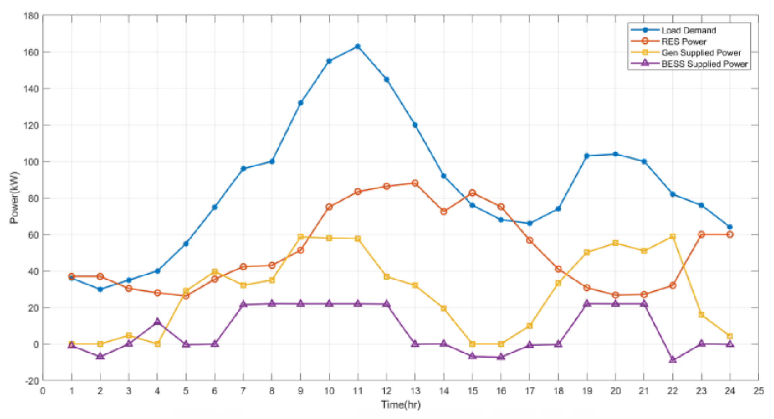
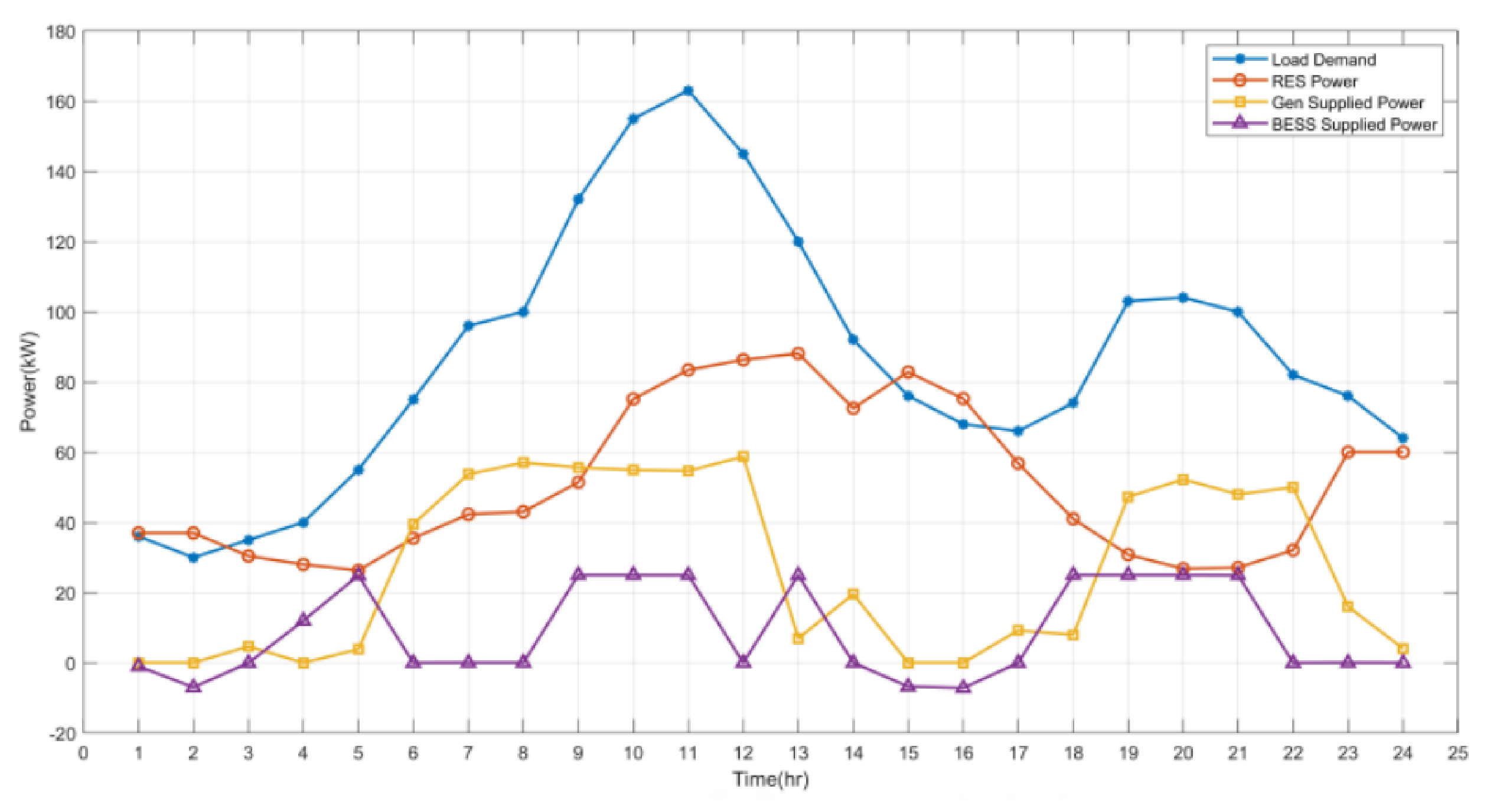
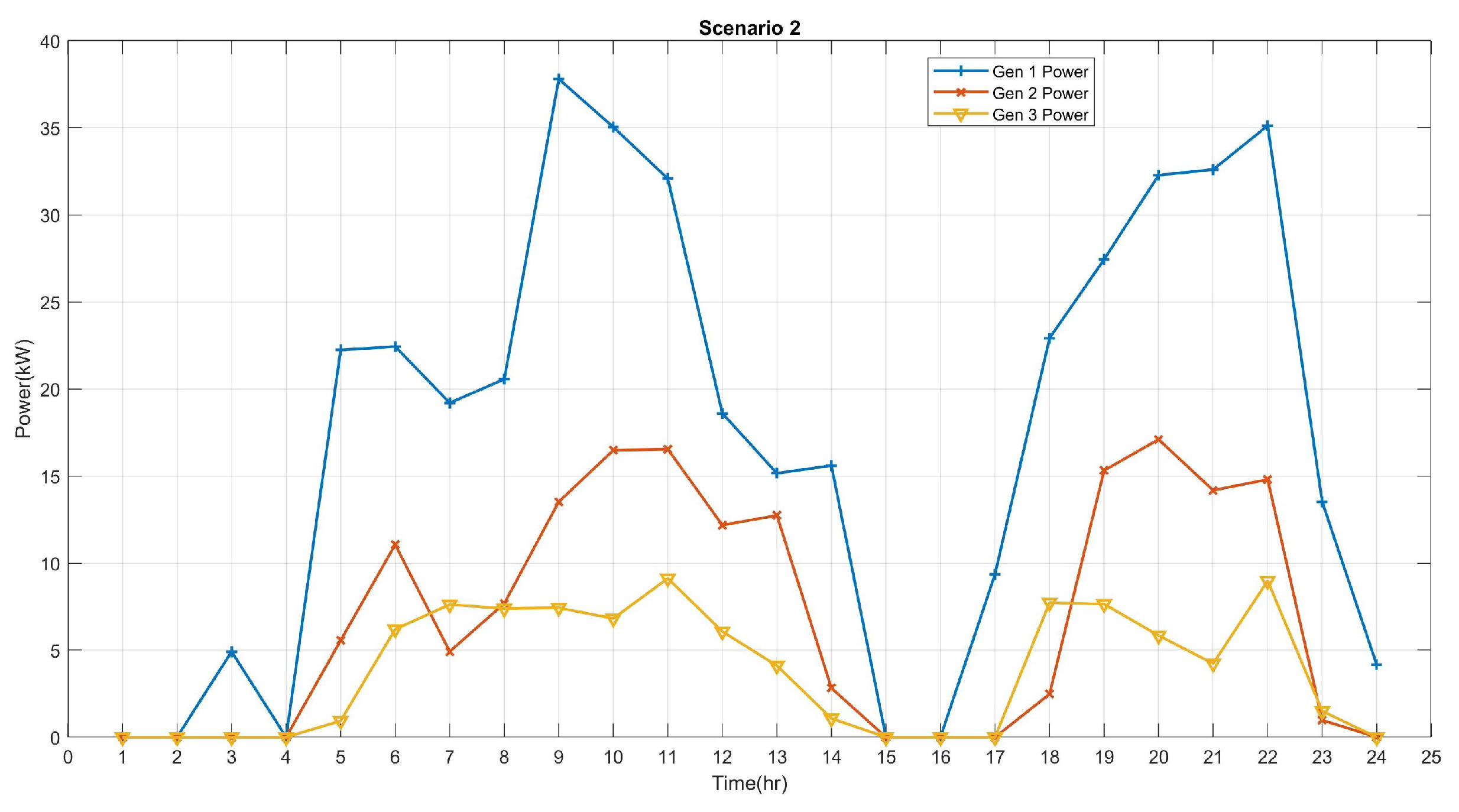
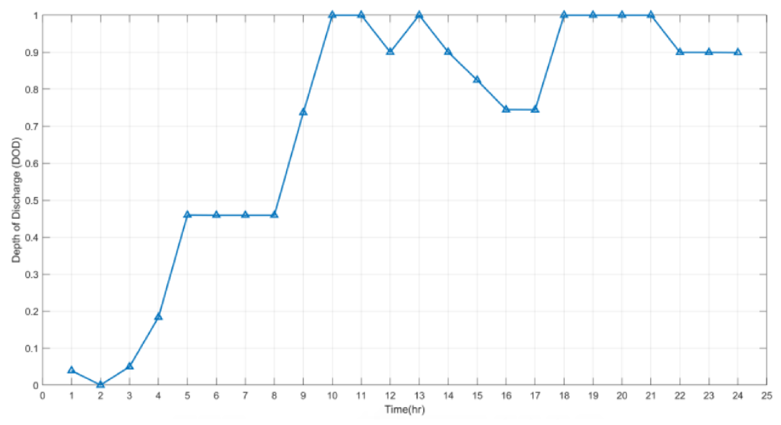
6.2. Scenario 2: BESS Connected Mode, with a Constant Battery Capacity of 100 kWh

From the first scenario, we have observed that the RES and diesel generators cannot always meet up with the load demand at all times. Furthermore, power would be wasted through the dump load at the times when the RES supply power exceeds the demand. The excess power could be made useful by allowing for the charging up of the battery. Hence, there is a need to install a BESS in the microgrid.
To investigate the effect of BESS on the operation of the microgrid, a BESS of a fixed 100 kWh capacity was added to the system. This capacity is expected to eliminated the power mismatch at any point in time. The power output of the RES, generators, and BESS at every time is shown in Figure 6. The scheduling cost and the total operating cost per day were found to be USD 246.2 and USD 293.85, respectively. The operation of the BESS could be observed during the hours of high demand. For example, the BESS charges between hours 2 and 3 and discharges between hours 6 and 8 due to an increase in the wind power. The BESS charges again between hours 8 and 11. Although there was an increase in the wind power and the output from the diesel generators, the combination of both is not enough to meet the peak demand, which occurs at hour 11. Therefore, there has to be some discharge from the BESS to meet this demand. The dispatch of the diesel generators in Scenario 2 is shown in Figure 7, and shows the dispatch of the individual generator in this scenario. This observation clearly demonstrates a relatively flexible operation of the microgrid. A significant observation is made between hours 15 and 16, during which, the outputs of all three generators are zero; this is a reflection of the fall in demand with a corresponding increase in wind power.
A decline in the BESS power is noticed between hours 13 and 16, when the demand dropped steadily as the BESS began to charge. Furthermore, at hour 18 through 21, the BESS power reflects the sharp increase in demand with a fall in wind power. This operation depicts that the battery only charges when the demand is less than the wind power and/or when the cost of discharging the battery is higher than the cost of the diesel generators; however, it may not be healthy for the battery due to being over-stressed.
The impact of the charging operation of the BESS described can be seen on the DOD of the BESS shown in Figure 8. The figure depicts that the DOD keeps changing as the BESS operates from charging to discharging, and that a unity DOD is attained at the peak demand or at the instants when there were reduced supplies from the other sources due to their operating limits. The consequence of this includes a high cost of operation of the battery, as well as a reduced lifespan. A high or unity DOD means that the BESS is operated at the maximum and/or beyond the allowed SOC limits of the BESS, which is not desirable for its healthy operation.

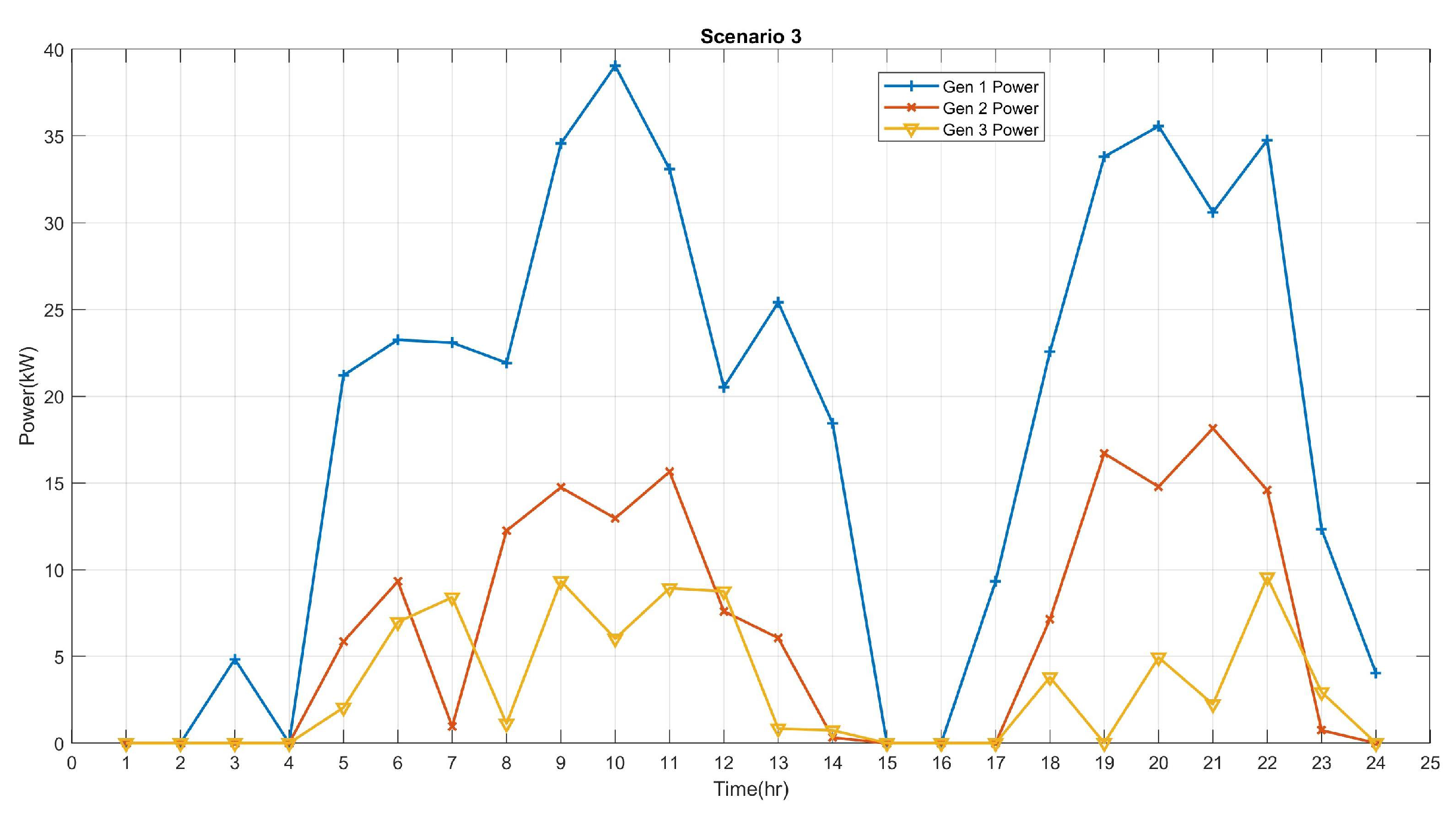
6.3. Scenario 3: BESS Connected Mode with Optimized Battery Capacity

In this scenario, we consider the optimal battery size that would produce a cost-effective and smooth operation of the system. We searched for the optimal battery size within a range of battery sizes that would yield a minimal operating cost whilst also ensuring a flexible operation and increased battery lifespan. The range of the battery sizes is from 100 kWh to 300 kWh, with a step size of 15 kWh.
In obtaining the optimal size, we considered all of the constraints and the power balance equation. The optimal capacity of the battery was found to be 150 kWh. For this scenario, the scheduling cost and total operating cost per day were obtained as USD 119.46 and USD 165.29, respectively. Both costs were less than the amount recorded in Scenario 2, since the microgrid operates at optimum capacity. The power output of the RES, generators, and BESS at every time is shown in Figure 9, where we can observe that the load demand was met at all times. Generator 1 has been given the most priority of the three generators because of its high power output limit and lower cost. This is noticed in the individual power dispatch by each generator, as shown in Figure 10. Furthermore, all generators responded to the change in the demand and output from the wind, as in Scenario 2.
When the battery capacity was not optimized in Scenario 2, the battery was heavily discharged in order to meet the demand. However, here, the DOD stays within the desired operating limit of the battery. This can be seen in the optimized plot of the DOD shown in Figure 11. The BESS was operated hourly, much like it is described in Scenario 2, and its DOD assumes a similar pattern but never hikes to unity. The highest DOD value is approximately 68%, at which point, the battery has to be charged in the next cycle; otherwise, its cost will be higher than that of the generators. Operating the battery within the DOD range guarantees a longer lifespan for the battery.
The dispatch of the battery power during its charging/discharging operation over the 24 h horizon is shown in Figure 12. A negative battery power indicates that the battery is charging and a positive power indicates that the battery is discharging. It can be observed that, for most of the time when the demand is high, the battery was discharging. This indicates a flexible and optimal operation of the BESS. The maximum discharge power at any time is set to 25 kW and the maximum charging power is set to −10 kW.

7. Conclusions

In this work, a technique for optimizing the size of the BESS in a wind-penetrated microgrid is proposed. In particular, we solved the optimization problem with the butterfly optimization algorithm due to its easy and fast implementation and ability to generate global optimized parameters. The optimal size of the battery was determined by minimizing the total daily operating cost of the microgrid. We found from our study that increasing the capacity of the BESS, which comes at an increased cost, does not necessarily reduce the operating cost. An incremental strategy based on the flexible operation and sizing of the BESS in the microgrid is conducted in order to achieve a minimal daily operating cost. Furthermore, our study revealed that an optimal size is necessary not only for economic operation but also for a healthy operation of the BESS. Finally, we conclude that it is crucial to obtain the optimal size of the ESS for an efficient and economic operation of the microgrid, as this would potentially help in elongating the lifespan of the battery. An alternative approach for obtaining the optimal capacity of the BESS is by using a search algorithm to size the BESS rather than an incremental approach on an assumed initial capacity. Such an approach may be computationally expensive, but it gives a more accurate value for the BESS capacity and the overall results. The proposed method is a general method that can be extended to solve any optimization problem involving other types of energy storage technologies irrespective of the location of the study.

Author Contributions

Conceptualization, B.O.A. and M.K.; Data curation, B.O.A. and U.T.S.; Formal analysis, B.O.A. and U.T.S.; Funding acquisition, M.K.; Investigation, U.T.S. and M.K.; Methodology, U.T.S., B.O.A. and M.K.; Project administration, M.K.; Resources, B.O.A., U.T.S. and M.K.; Software, U.T.S. and B.O.A.; Supervision, U.T.S. and M.K.; Validation, U.T.S. and M.K.; Visualization, U.T.S., B.O.A. and M.K.; Writing—original draft, B.O.A. and U.T.S.; Writing—review & editing, U.T.S. and M.K.; B.O.A. and U.T.S. contributed equally to this paper. All authors have read and agreed to the published version of the manuscript.

Funding

The Deanship of Research at King Fahd University of Petroleum and Minerals through the project No. DF201011.

Acknowledgments

The authors would like to acknowledge the support provided by the Deanship of Research (DSR) at King Fahd University of Petroleum and Minerals (KFUPM) for funding this work through project No. DF201011. In addition, we would like to acknowledge the funding support provided by the King Abdullah City for Atomic and Renewable Energy (K.A. CARE).

Conflicts of Interest

The authors declare no conflict of interest.

Abbreviations

The following abbreviations are used in this manuscript:
aPower exponent
a i , b i , c i Fuel cost coefficients for generation unit i
d i , e i , f i Emission cost coefficients for generation unit i
A C Alternating current
B E S S Battery energy storage system
B O Butterfly optimization
B O A Butterfly optimization algorithm
cSensory modality of BOA
C E Cost of electricity, USD/MWh
C B E S S Cost function of battery energy storage system
C d . g e n Total operating cost of diesel generation units, USD/MWh
C b ( t ) Battery cost at time t, USD
C b , c a p Initial battery capacity cost, USD
C g ( t ) Generator cost at time t, USD
C w ( t ) Wind cost at time t, USD
C W T Daily cost of wind power dissipation, USD/MWh
C M G e x Cost of power exchanged, USD/MWh
C O A Cayote optimization algorithm
C R F Capital recovery cost, USD
D G i Power generated by diesel generation unit i, MW
D O D 
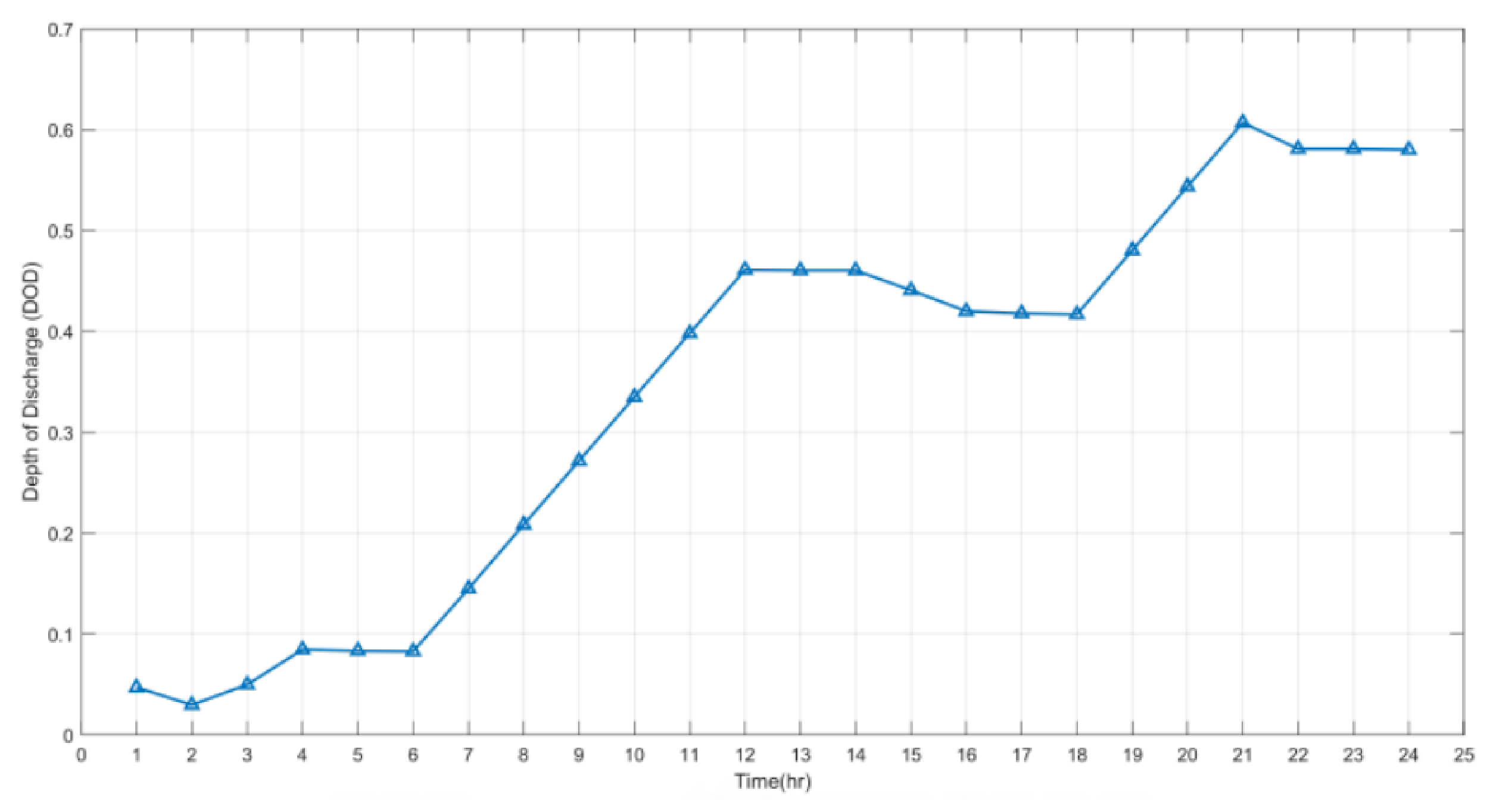
Depth of discharge of energy storage system, MWh
D O D b ( t ) Depth of discharge of battery energy storage system at time t, MWh
E b Battery energy
E b m a x Maximum rated energy of battery, MWh
E b m i n Minimum rated energy of battery, MWh
E S S Energy storage system
E s t o Battery storage capacity
η b Battery efficiency, USD/MWh
η b , c h ( t ) Charging efficiency of battery at time t
η b , d c h ( t ) Discharging efficiency of battery at time t
f i Fragrance of the i t h butterfly
F C Fuel cost, USD/MWh
F F O Firefly optimization
G A Genetic algorithm
G W O Grey-wolf optimization
IStimulus intensity
I C w Initial wind plant cost, USD
i r Interest rate
i y Projected battery lifetime, in years
JObjective function
L i i o n Lead ion
M G Microgrid
n c D O D Number of cycles of energy storage at a particular DOD
N i C d Nickel–cadmium
P b , c h ( t ) Charging power of the battery at time t
P b , d c h ( t ) Discharging power of the battery at time t
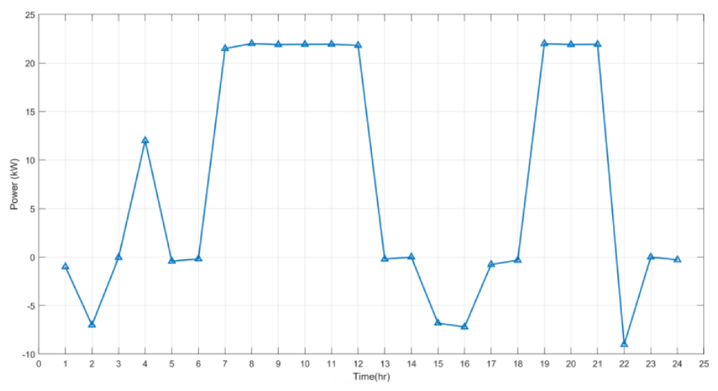
P B E S S Battery power, MW
E B E S S Battery energy, MWh
P D Load power demand, MW
P g Grid power, MW
P g , i Output power of the generation unit im MW
P L ( t ) Demanded or load power at time t, MW
P w Wind power output, MW
P w , t Wind power output at time t, MW
P b ( t ) Battery power at time t, MW
P b m a x Maximum rated power of battery, MW
P b m i n Minimum rated power of battery, MW
P M m a x Maximum capacity of the transmission line, MVA
P S O Particle swarm optimization
P V Photo-voltaic
rA random number
R E Renewable energy
R E S Renewable energy sources
S O C State of charge
S O C b ( t ) State of charge of battery at time t
TPeriod
tIteration number
U P S Uninterrupted power supply
v C I Wind cut-in speed, km/h
v R Rated wind speed, km/h
v t Wind speed at time t, km/h
W O A Whale optimization algorithm
x i t solution vector for the i th butterfly at iteration t

References

  1. Tiamiyu, R.A.; Salman, U.T. Deficit in Leadership Qualities Negating Efforts in Curtailing Climate Change. Environ. Ecol. Res. 2021, 9, 215–223. [Google Scholar] [CrossRef]
  2. Gao, D.W. Energy Storage for Sustainable Microgrid; Academic Press: Cambridge, MA, USA, 2015. [Google Scholar]
  3. Bahramirad, S.; Daneshi, H. Optimal sizing of smart grid storage management system in a microgrid. In Proceedings of the 2012 IEEE PES Innovative Smart Grid Technologies (ISGT), Washington, DC, USA, 16–20 January 2012; pp. 1–7. [Google Scholar] [CrossRef]
  4. Salman, U.; Khan, K.; Alismail, F.; Khalid, M. Techno-Economic Assessment and Operational Planning of Wind-Battery Distributed Renewable Generation System. Sustainability 2021, 13, 6776. [Google Scholar] [CrossRef]
  5. Simeon, M.; Adoghe, A.U.; Wara, S.T.; Oloweni, J.O. Renewable Energy Integration Enhancement Using Energy Storage Technologies. In Proceedings of the 2018 IEEE PES/IAS PowerAfrica, Cape Town, South Africa, 28–29 June 2018; pp. 864–868. [Google Scholar] [CrossRef]
  6. Malkowski, R.; Bucko, P.; Jaskólski, M.; Pawlicki, W.; Stoltmann, A. Simulation of the Dynamics of Renewable Energy Sources with Energy Storage Systems. In Proceedings of the 2018 15th International Conference on the European Energy Market (EEM), Lodz, Poland, 27–29 June 2018; pp. 1–5. [Google Scholar] [CrossRef]
  7. Liu, X.; Su, B. Microgrids—An integration of renewable energy technologies. In Proceedings of the 2008 China International Conference on Electricity Distribution, Guangzhou, China, 10–13 December 2008. [Google Scholar]
  8. Ahmed, A.; Jiang, T. Operation Management of Power Grid System with Renewable Energy Sources and Energy Storage System Integrations. In Proceedings of the 2018 2nd IEEE Conference on Energy Internet and Energy System Integration (EI2), Beijing, China, 20–22 October 2018; pp. 1–6. [Google Scholar] [CrossRef]
  9. Viral, R.; Khatod, D. Optimal planning of distributed generation systems in distribution system: A review. Renew. Sustain. Energy Rev. 2012, 16, 5146–5165. [Google Scholar] [CrossRef]
  10. Parhizi, S.; Lotfi, H.; Khodaei, A.; Bahramirad, S. State of the art in research on microgrids: A review. IEEE Access 2015, 3, 890–925. [Google Scholar] [CrossRef]
  11. Ghiassi-Farrokhfal, Y.; Rosenberg, C.; Keshav, S.; Adjaho, M. Joint Optimal Design and Operation of Hybrid Energy Storage Systems. IEEE J. Sel. Areas Commun. 2016, 34, 639–650. [Google Scholar] [CrossRef] [Green Version]
  12. Pandžić, H.; Bobanac, V. An accurate charging model of battery energy storage. IEEE Trans. Power Syst. 2019, 34, 1416–1426. [Google Scholar] [CrossRef]
  13. Bradbury, K.; Pratson, L.; Patiño-Echeverri, D. Economic viability of energy storage systems based on price arbitrage potential in real-time US electricity markets. Appl. Energy 2014, 114, 512–519. [Google Scholar] [CrossRef]
  14. Akhil, A.A.; Huff, G.; Currier, A.B.; Kaun, B.C.; Rastler, D.M.; Chen, S.B.; Cotter, A.L.; Bradshaw, D.T.; Gauntlett, W.D. Electricity Storage Handbook in Collaboration with NRECA; Sandia National Laboratories: Albuquerque, NM, USA, 2013.
  15. San Martín, J.I.; Zamora, I.; San Martín, J.J.; Aperribay, V.; Eguia, P. Energy Storage Technologies for Electric Applications. Kernel Description. Available online: http://www.sc.ehu.es/sbweb/energias-renovables/temas/almacenamiento/almacenamiento.html (accessed on 4 January 2020).
  16. Fathima, A.H.; Palanisamy, K. Battery energy storage applications in wind integrated systems—A review. In Proceedings of the 2014 International Conference on Smart Electric Grid (ISEG), Guntur, India, 19–20 September 2014; pp. 1–8. [Google Scholar] [CrossRef]
  17. Sebastián, R.; Peña-Alzola, R. Study and simulation of a battery based energy storage system for wind diesel hybrid systems. In Proceedings of the 2012 IEEE International Energy Conference and Exhibition (ENERGYCON), Florence, Italy, 9–12 September 2012; pp. 563–568. [Google Scholar] [CrossRef]
  18. Fossati, J.P.; Galarza, A.; Martín-Villate, A.; Fontan, L. A method for optimal sizing energy storage systems for microgrids. Renew. Energy 2015, 77, 539–549. [Google Scholar] [CrossRef]
  19. Sharma, S.; Bhattacharjee, S.; Bhattacharya, A. Grey wolf optimisation for optimal sizing of battery energy storage device to minimise operation cost of microgrid. IET Gener. Transm. Distrib. 2016, 10, 625–637. [Google Scholar] [CrossRef]
  20. Yuan, Z.; Wang, W.; Wang, H.; Yildizbasi, A. A new methodology for optimal location and sizing of battery energy storage system in distribution networks for loss reduction. J. Energy Storage 2020, 29, 101368. [Google Scholar] [CrossRef]
  21. Zolfaghari, M.; Ghaffarzadeh, N.; Ardakani, A.J. Optimal sizing of battery energy storage systems in off-grid micro grids using convex optimization. J. Energy Storage 2019, 23, 44–56. [Google Scholar] [CrossRef]
  22. Wong, L.A.; Ramachandaramurthy, V.K.; Walker, S.L.; Taylor, P.; Sanjari, M.J. Optimal placement and sizing of battery energy storage system for losses reduction using whale optimization algorithm. J. Energy Storage 2019, 26, 100892. [Google Scholar] [CrossRef]
  23. Zhang, Y.; Su, Y.; Wang, Z.; Liu, F.; Li, C. Cycle-Life-Aware Optimal Sizing of Grid-Side Battery Energy Storage. IEEE Access 2021, 9, 20179–20190. [Google Scholar] [CrossRef]
  24. Eroshenko, S.A.; Samoylenko, V.O.; Pazderin, A.V. Renewable energy sources for perspective industrial clusters development. In Proceedings of the 2016 2nd International Conference on Industrial Engineering, Applications and Manufacturing (ICIEAM), Chelyabinsk, Russia, 19–20 May 2016; pp. 1–5. [Google Scholar] [CrossRef]
  25. Rafique, M.; Rehman, S.; Alam, M.; Alhems, L. Feasibility of a 100 MW Installed Capacity Wind Farm for Different Climatic Conditions. Energies 2018, 11, 2147. [Google Scholar] [CrossRef] [Green Version]
  26. Yang, Z.; Xia, L.; Guan, X. Fluctuation Reduction of Wind Power and Sizing of Battery Energy Storage Systems in Microgrids. IEEE Trans. Autom. Sci. Eng. 2020, 17, 1195–1207. [Google Scholar] [CrossRef]
  27. Salman, U.T.; Al-Ismail, F.S.; Khalid, M. Optimal Sizing of Battery Energy Storage for Grid-Connected and Isolated Wind-Penetrated Microgrid. IEEE Access 2020, 8, 91129–91138. [Google Scholar] [CrossRef]
  28. Sufyan, M.; Rahim, N.A.; Tan, C.K.; Muhammad, M.A.; Raihan, S.R.S. Optimal sizing and energy scheduling of isolated microgrid considering the battery lifetime degradation. PLoS ONE 2019, 14, e0211642. [Google Scholar] [CrossRef]
  29. Abdulgalil, M.A.; Khalid, M.; Alismail, F. Optimal sizing of battery energy storage for a grid-connected microgrid subjected to wind uncertainties. Energies 2019, 12, 2412. [Google Scholar] [CrossRef] [Green Version]
  30. Rehman, S.; Umar, T.; Salman, L.M.A. Wind Farm-Battery Energy Storage Assessment in Grid-Connected Microgrids. Energy Eng. 2020, 117, 343–365. [Google Scholar] [CrossRef]
  31. Krishan, O.; Suhag, S. A novel control strategy for a hybrid energy storage system in a grid-independent hybrid renewable energy system. Int. Trans. Electr. Energy Syst. 2020, 30, e12262. [Google Scholar] [CrossRef]
  32. Salman, U.T.; Abdulgalil, M.A.; Wasiu, O.S.; Khalid, M. Energy Management Strategy Considering Battery Efficiency for Grid-Tied Microgrids During Summer in the Kingdom of Saudi Arabia. In Proceedings of the 2019 8th International Conference on Renewable Energy Research and Applications (ICRERA), Brasov, Romania, 3–6 November 2019; pp. 422–427. [Google Scholar]
  33. Zhou, C.; Qian, K.; Allan, M.; Zhou, W. Modeling of the cost of EV battery wear due to V2G application in power systems. IEEE Trans. Energy Convers. 2011, 26, 1041–1050. [Google Scholar] [CrossRef]
  34. Khorramdel, H.; Aghaei, J.; Khorramdel, B.; Siano, P. Optimal Battery Sizing in Microgrids Using Probabilistic Unit Commitment. IEEE Trans. Ind. Inform. 2016, 12, 834–843. [Google Scholar] [CrossRef]
  35. Arora, S.; Singh, S. Butterfly optimization algorithm: A Novel Approach for Global Optimization. Soft Comput. 2019, 23, 715–734. [Google Scholar] [CrossRef]
  36. Alahmed, A.; Taiwo, S.; Abido, M. Implementation and Evaluation of Grey Wolf optimization Algorithm on Power System Stability Enhancement. In Proceedings of the 2019 IEEE 10th GCC Conference & Exhibition (GCC), Kuwait, Kuwait, 9–23 April 2019; pp. 1–6. [Google Scholar]
  37. Abdul-Rashid, R.; Alawode, B.O. Robustness Evaluation of the Butterfly Optimization Algorithm on a Control System. arXiv 2019, arXiv:1912.00185. [Google Scholar]
  38. Tubishat, M.; Alswaitti, M.; Mirjalili, S.; Al-Garadi, M.A.; Alrashdan, M.T.; Rana, T.A. Dynamic Butterfly Optimization Algorithm for Feature Selection. IEEE Access 2020, 8, 194303–194314. [Google Scholar] [CrossRef]
  39. Abdulhussein, K.G.; Yasin, N.M.; Hasan, I.J. Comparison between butterfly optimization algorithm and particle swarm optimization for tuning cascade PID control system of PMDC motor. Int. J. Power Electron. Drive Syst. 2021, 12, 736–744. [Google Scholar] [CrossRef]
  40. Yang, D.; Wang, X.; Tian, X.; Zhang, Y. Improving monarch butterfly optimization through simulated annealing strategy. J. Ambient. Intell. Humaniz. Comput. 2020, 1–12. Available online: https://www.researchgate.net/profile/Ihsan-Hasan-2/publication/352368105_Comparison_between_butterfly_optimization_algorithm_and_particle_swarm_optimization_for_tuning_cascade_PID_control_system_of_PMDC_motor/links/60c6918292851ca6f8e9b577/Comparison-between-butterfly-optimization-algorithm-and-particle-swarm-optimization-for-tuning-cascade-PID-control-system-of-PMDC-motor.pdf (accessed on 16 November 2021). [CrossRef] [Green Version]
  41. Parambil, R.K. Economic Load Dispatch Problem Using Butterfly Optimization Algorithm. Eur. J. Mol. Clin. Med. 2020, 7, 2773–2778. [Google Scholar]
Figure 1. Characteristics of different ESS technologies.
Electronics 11 00109 g001
Figure 2. The proposed microgrid system.
Electronics 11 00109 g002
Figure 3. BO Algorithm flowchart.
Electronics 11 00109 g003
Figure 4. A residential demand profile and a wind power profile.
Electronics 11 00109 g004
Figure 5. Power dispatch by the microgrid in Scenario 1.
Electronics 11 00109 g005
Figure 6. Power dispatched by the microgrid in Scenario 2.
Electronics 11 00109 g006
Figure 7. Generator power dispatched in Scenario 2.
Electronics 11 00109 g007
Figure 8. The depth of discharge of BESS in Scenario 2.
Electronics 11 00109 g008
Figure 9. Power dispatched by the microgrid in Scenario 3.
Electronics 11 00109 g009
Figure 10. Generator power dispatched in Scenario 3.
Electronics 11 00109 g010
Figure 11. The depth of discharge of BESS in Scenario 3.
Electronics 11 00109 g011
Figure 12. Charging and discharging operation of BESS in Scenario 3.
Electronics 11 00109 g012
Table 1. Generator parameters.
Diesel 1Diesel 2Diesel 3
a i  ($/kW2)0.00010.00010.0001
b i  ($/kW)0.04380.04790.0490
c i  ($)0.30.50.4
P m i n  (kW)0.00.00.0
P m a x  (kW)40.020.010.0
Table 2. System parameters.
ParameterValue
Initial SOC (%)80
S O C b a t t m a x (%)90
S O C b a t t m i n (%)10
Initial Capital Cost ($/kWh)625
Maintenance Cost ($/kWh)/year25
Round-trip Efficiency (%)90
Lifetime (years)3
P b a t t m i n (kW)10
P b a t t m a x (kW)25
Interest Rate (%)6
Publisher’s Note: MDPI stays neutral with regard to jurisdictional claims in published maps and institutional affiliations.

