1. Introduction
In recent years, the need for a more formal requirement verification process and the need for language and tool support has been increasingly recognized by the cyber–physical modeling community. Several research works on language and tool support have been published in this area (e.g., [
1,
2,
3,
4]).
To ensure the proper operation of complex physical systems (e.g., power plants, aircraft, vehicles, building automation, and robotics), requirements are issued at different points in time during the system’s development life cycle: from the design phase to the operation phase. Having both the requirements and the model in the same language reduces the semantic gap in the terminology used to communicate between requirement verification engineers and system modelers. It also simplifies the modeling effort and allows for the automated combination and integration of requirement models.
However, in an industrial scale with projects involving complex systems with a large number of requirements and several teams working on different parts of the system, it is still difficult to analyze the results of the requirement verification process just by inspecting the simulation results. Different artifacts in the system evolve at different paces and are modified by different stakeholders. Analyzing how these changes inter-relate and ensuring the consistency of the system can be very complicated. Traceability, defined as “the ability to describe and follow the life of a requirement, in both a forwards and backwards direction” [
5], plays an important role in maintaining consistency in the system as it can be used to reason about a logical connection between heterogeneous artifacts throughout the development life cycle. It can be used to support several different software and system engineering activities, including requirement tracing [
6], change impact analysis [
7], software maintenance [
8], reverse engineering [
9], and consistency checking [
10].
In order to realize the benefits of traceability and to ensure that the resulting systems are well-tested and evaluated, traceability needs to be established between artifacts that are produced throughout the development life cycle. However, due to the heterogeneity and complexity of CPSs, different modeling languages and tools are often utilized to address the different aspects of the system and development activities such as requirements engineering, system design, verification, etc. Hence, different stakeholders are usually responsible for different artifacts and activities in the project and these are realized in isolation using a variety of domain-specific tools and languages.
Several studies (e.g., [
11,
12,
13,
14,
15]) report that diverse heterogeneous artifacts and tools in the development life cycle are a challenge to be faced when establishing traceability links. From the studies, one of the solutions for this challenge is tool integration where all existing tools are connected so that it becomes possible to exchange information about the heterogeneous artifacts and create traceability links between them. This was achieved for CPS development in our previous work [
16], in which some of the components of the traceability framework were developed. What is currently missing is an integrated tool platform to establish, maintain, and use the traceability links of heterogeneous artifacts and activities (e.g., requirements, design models, scenario models, simulation results, validation, and verification) in the development life cycle. The open-source environment OpenModelica (see also:
https://www.openmodelica.org accessed on 31 March 2021) [
17] has the potential to contribute to such a platform because it already supports all of the activities in the development life cycle. This work integrates the previously developed traceability components with new ones into an integrated system inside the OpenModelica tool. OpenModelica is an integrated open-source environment for modeling, simulation, optimization, model-based development, and analysis of large-scale CPSs. The environment is based on the equation-based object-oriented Modelica modeling language standard [
18,
19] and the Functional Mockup Interface (FMI) standard [
20,
21] for model exchange and co-simulation.
This paper describes a semi-automatic and collaborative feature for creation and maintenance of traceability links within an integrated environment for modeling, simulation, and model-based development of CPSs. The objective of this article was to answer the following Research Question (RQ):
RQ. How can heterogeneous artifacts be enriched with links that are designed and maintained to better support traceability and change impact analysis in requirements verification of CPSs?
A design science approach [
22,
23] was used to tackle the research question. First, traceability challenges that remain unresolved are identified. Then, a solution was designed to address the problem; this design was implemented in a software prototype as a proof-of-concept. A case study was used to demonstrate the applicability of the resulting prototype design.
To address the research question, the following contributions were made to the model-based development of CPSs:
We designed a collaborative approach based on the Open Services for Lifecycle Collaboration (OSLC) standard for creating and maintaining traceability links semi-automatically.
We developed an integrated framework for traceability in the development process based on our design.
We demonstrated the applicability and usefulness of our prototype in practice with a use-case tracing of heterogeneous artifacts during the model-based development of a CPS.
The remainder of this paper is organized as follows.
Section 2 presents the current traceability challenges.
Section 3 discusses Virtual Verification of Designs against Requirements (vVDR) and OSLC. The architectural design and the implementation aspects of the integrated traceability framework are described in
Section 4 and
Section 5, respectively.
Section 6 presents a case study that demonstrates the applicability of our prototype implementation followed by an overview of related work in
Section 7. Finally, concluding remarks and future research work are provided in
Section 8.
2. Traceability Challenges
Over the past 30 years, several researchers have conducted empirical studies to identify the challenges of traceability. Gotel and Finkelstein [
5] conducted an empirical study to analyze the problem regarding requirements traceability in industry. In 2012, Gotel et al. [
24,
25] identified the grand traceability challenges that need to be addressed before 2035—that traceability will be established in the background and will be seamless to software and systems engineering tasks. According to this study, further research must be done to ensure that traceability is: purposeful, cost-effective, configurable, trusted, scalable, portable, valued, and ubiquitous.
In recent work, Salome et al. [
15] conducted a literature review with an industrial case study with the aim of identifying traceability challenges and solutions in the automotive domain. They explored 17 traceability challenges applicable to the automotive industry out of the 22 general challenges identified in the literature. In addition, they further identified six challenges that were partially solved while six others remain unsolved based on their industrial case even though some solutions are suggested in the literature. In the following, we present the five challenges we selected to solve (four unsolved challenges and one partially solved challenge in the industry identified by Salome et al. [
15]). We intend to use the remaining unselected challenges as a part of future work as they need industrial use cases and close collaboration with industry.
- C1:
Manual work—Manually creating and updating traceability links that involve a large number of heterogeneous artifacts is a time-consuming and error-prone task [
26] and should be performed by automated tools. To address this challenge, the use of automated approaches (e.g., event-based techniques [
12] and model-driven techniques [
27]) has been suggested in the literature.
- C2:
Traceability perceived as overhead—Managing trace links manually adds overhead for developers since their primary goal is to develop software. The main reason behind this is that the creators and actual beneficiaries of the traceability links are not always the same people (e.g., [
28,
29,
30]). To overcome this challenge, some literature (e.g., [
5,
12,
31,
32,
33]) proposed a solution to automate the generation of traceability links whenever possible.
- C3:
Lack of visualization tools—Traceability links are usually presented in large tables or lists where it is difficult to understand and analyze traceability information, especially in large projects. The users need visualization tools to be able use the links and facilitate development activities.
- C4:
Lack of universal standards—Traceability needs to be exchanged between stakeholders who are involved in developing heterogeneous artifacts throughout the development life cycle. Currently, traceability information is stored in different forms. Accessing and exchanging traceability information is difficult without a common standard that defines how it is created and stored. Hence, a common standardized format is needed to facilitate the sharing and transfer of traceability information.
- C5:
Diverse artifacts and tools—A common situation in industry is that a system model is composed of several sub-models that may have been developed using different tools and operations, such as requirements modeling, model simulation, system design, validation, and verification; therefore, the heterogeneous artifacts produced can be specified using various modeling languages and tools. Most traceability tools either do not support linking to artifacts located outside the tool or only support linking to specific tools and a specific format [
12,
15,
34].
With respect to the grand traceability challenges, the main problems are: making traceability cost-effective (C1, C2), scalable (C3, C5), and portable (C4). The existence of these challenges serves as the main motivation for our research. Since the overall objective is to improve the traceability tools for CPSs, the aim of this paper was to provide a solution through an integrated traceability tool in model-based development and demonstrate it in practice on a use case.
3. Basic Concepts and Method
Model-Based Systems Engineering (MBSE) is defined as “the formalized application of modeling to support system requirements, design, analysis, verification, and validation activities beginning in the conceptual design phase and continuing throughout development and later life cycle phases” [
35]. It relies on building models that replace or complement requirements expressed in natural language so that the system design can be verified against requirements. An overview of existing methodologies used in industry is presented by Jeff A. Estefan [
36]. Some of them use standardized languages (e.g., SysML [
37] and Unified Modeling Language (UML) [
38]) and tools (e.g., ModelicaML [
39,
40]) for system modeling.
The approach developed in this paper builds on previous work that automates the generation of verification models [
41] and adds support for requirement verification [
42,
43] in Modelica. Traceability support is based on the OSLC specification. An overview of the basic concepts and methods from the domain is given in the following subsections.
3.1. Virtual Verification of Designs against Requirements
Virtual verification of designs against requirements (vVDR) is a method that enables model-based system design verification against requirements. The vVDR methodology has been validated on a number of industrial use-cases [
41,
44].
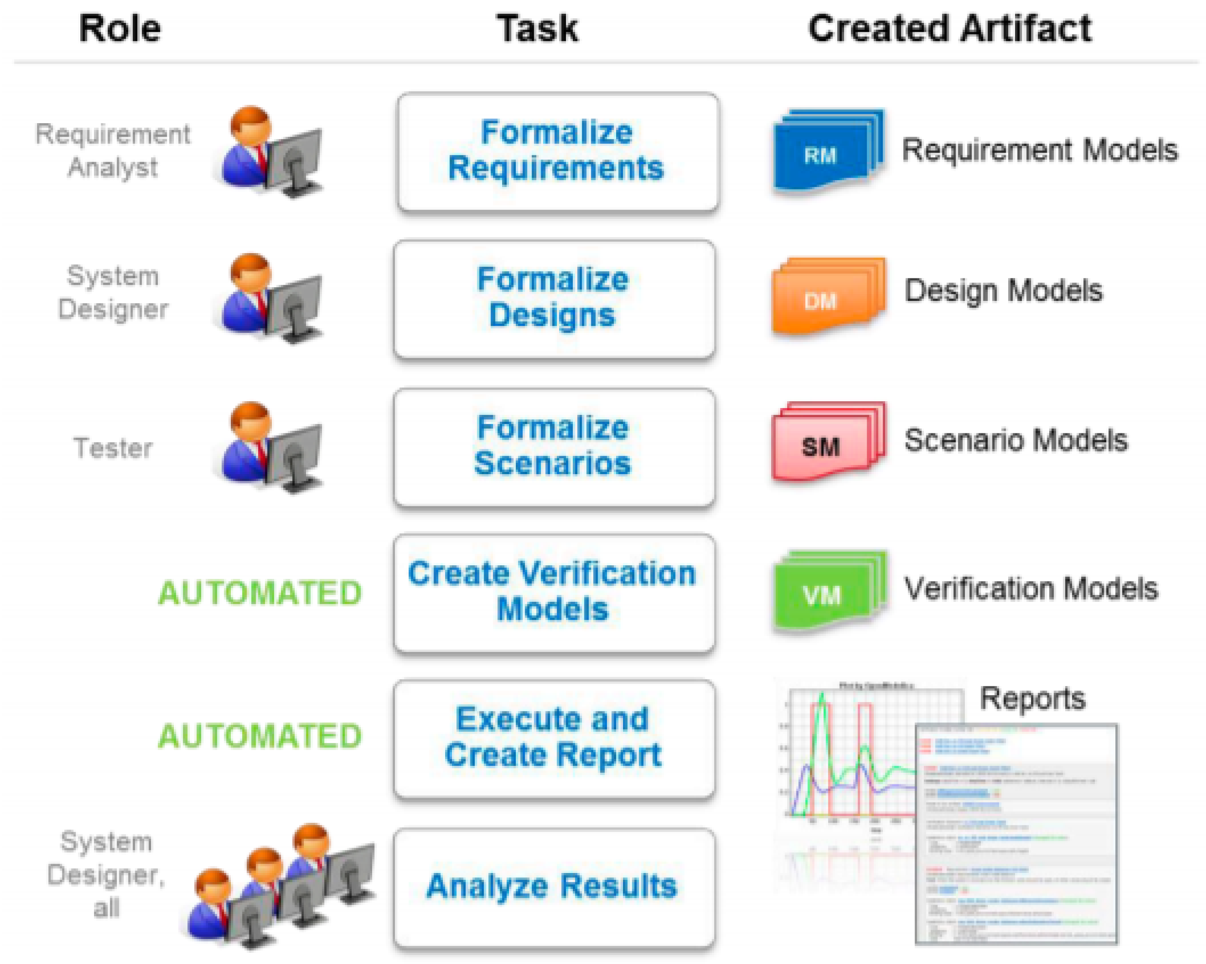
Figure 1 shows the basic steps of the vVDR method and the artifacts created.
The vVDR model defines the following modeling artifacts as the necessary building blocks:
Requirement Model—Each requirement is represented by a model and the requirement status is computed throughout the simulation.
System Design Model—A particular design alternative or version of the system is represented by a model to be used for verification against requirements. Several design alternatives can be included in the verification process (e.g., different configurations of the system).
Scenario Model—A scenario defines how the system is stimulated during the simulation.
Verification Model—A verification model is the combination of a set of requirements, design alternatives, and a scenario. A verification model can be defined by the user or generated automatically. It is used to perform design verification and to report on requirement violations.
Requirement models are the output of the Formalize Requirements activity and are the input to the Formalize Designs activity. Design and requirement models are input to the Formalize Scenarios activity that output scenario models. Requirement, design, and scenario models are input to the Create Verification Models activity, which outputs verification models to be used for analysis in the Execute and Create Report step. The generated reports and all the various models are, finally, input to the Analyze Results activity. To facilitate the generation of verification reports, the vVDR library’s requirement interface provides a status variable for each requirement. This status variable can take one of the following values:
Violated—When the conditions of the requirement are not fulfilled by the design model and is represented by −1 in the plots.
Not_violated—When the conditions of the requirement are fulfilled by the design model and is represented by 1 in the plots.
Not_applicable—When the requirement does not apply. For instance, a requirement that describes the behavior of the heating system when the power is lost cannot be verified if there is no test scenario in which power loss occurs. This value is used to identify requirements that were never tested during a simulation and is represented by 0 in the plots.
For each requirement simulated, the status value is used to determine whether it is verified, violated, or never tested during a particular system configuration.
3.2. Open Services for Lifecycle Collaboration
Open Services for Lifecycle Collaboration (OSLC) [
45] is an open-source initiative for creating a set of specifications that enables integration of development life cycle tools (e.g., modeling tools, change management tools, requirements management tools, quality management tools, and configuration management tools). The goal of OSLC is to make it easier for tools to work together by specifying a light-weight protocol without standardizing the behavior of a specific tool. OSLC is based on the RESTful [
46] web services architectural pattern, through which other applications can interconnect and access shared data. The OSLC specifications use a linked data [
47] model to enable integration at the data level via links between artifacts. The structure and semantics of the artifact information being exchanged between applications is represented using the Resource Description Framework (RDF) [
48]. RDF is a language used to represent information such as a web resource identified by a unique Uniform Resource Identifier (URI) using various syntax notations and data serialization formats. This enables the data from different sources to be connected and queried by different clients.
4. Architectural Design
The design is based on a standardized interface and format using OSLC.
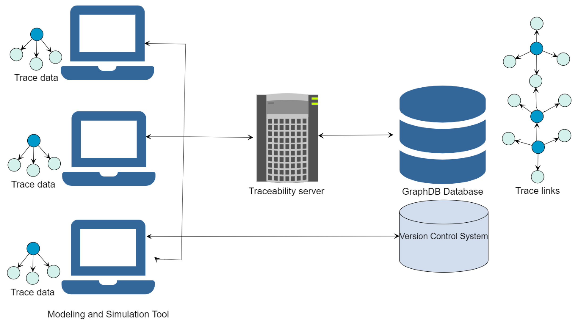
Figure 2 depicts the architectural design of our approach showing the different components that it relies on.
As illustrated in
Figure 2, the architecture consists of four components:
Modeling and Simulation Tool—The modeling and simulation tools act as a front-end to the traceability server. Any tool written in any programming language can interconnect with the traceability server, and provide or access the trace data. The tools send the traceability information from activities that are performed within the tools to an OSLC-based traceability server.
Traceability Server—The traceability server is an OSLC compliant tool interface implemented as a set of RESTful services. Its main responsibility is to create an OSLC compliant HTTP port to listen for the POST and GET actions. It acts as a front-end to a triplestore database (both for writing traceability information into the database and retrieving traceability data from the database).
GraphDB Database—The GraphDB database is an RDF triplestore serving as a global database to store the The Provenance Notation (PROV) and OSLC triples (trace links) that make up the traceability data.
Version Control System—The Git Version Control System is used as a central artifact management system that interacts with the modeling tools by establishing a unique URI for artifacts that are evolved by different users. The traceability links are unique as they are based on the Git commit hash. This allows multiple users to work on the project and maintain traceability links simultaneously.
The concepts from the PROV [
49] and OSLC [
45] specifications are used to represent the traceability information. PROV provides a set of relations to describe the use and creation of entities by activities, which may be influenced in various ways by agents.
Entities—An entity is a physical, digital, conceptual, or other kind of thing with certain fixed aspects. In the case of our prototype, this would include artifacts such as requirement documents and models, design models, scenario models, verification models, verification reports, simulation results, etc.
Activities—An activity is something that occurs over a period of time and acts upon or together with entities. It may include using, processing, transforming, modifying, or generating entities. In our work, activities include creating and modifying models, simulations, verifications, and reports.
Agents—An agent is a user who performs an activity and bears some form of responsibility for the existence of an entity. Agents include individual engineers such as developers, architects, analysts, and project managers.
In addition, relations are defined that describe the connection between entities, activities, and agents. In the context of traceability, the traceability data consist of triples made up of subject, predicate, and object, where subject and object are either an entity, activity, or agent. The predicate is either an OSLC [
50] or PROV [
49] relationship type.
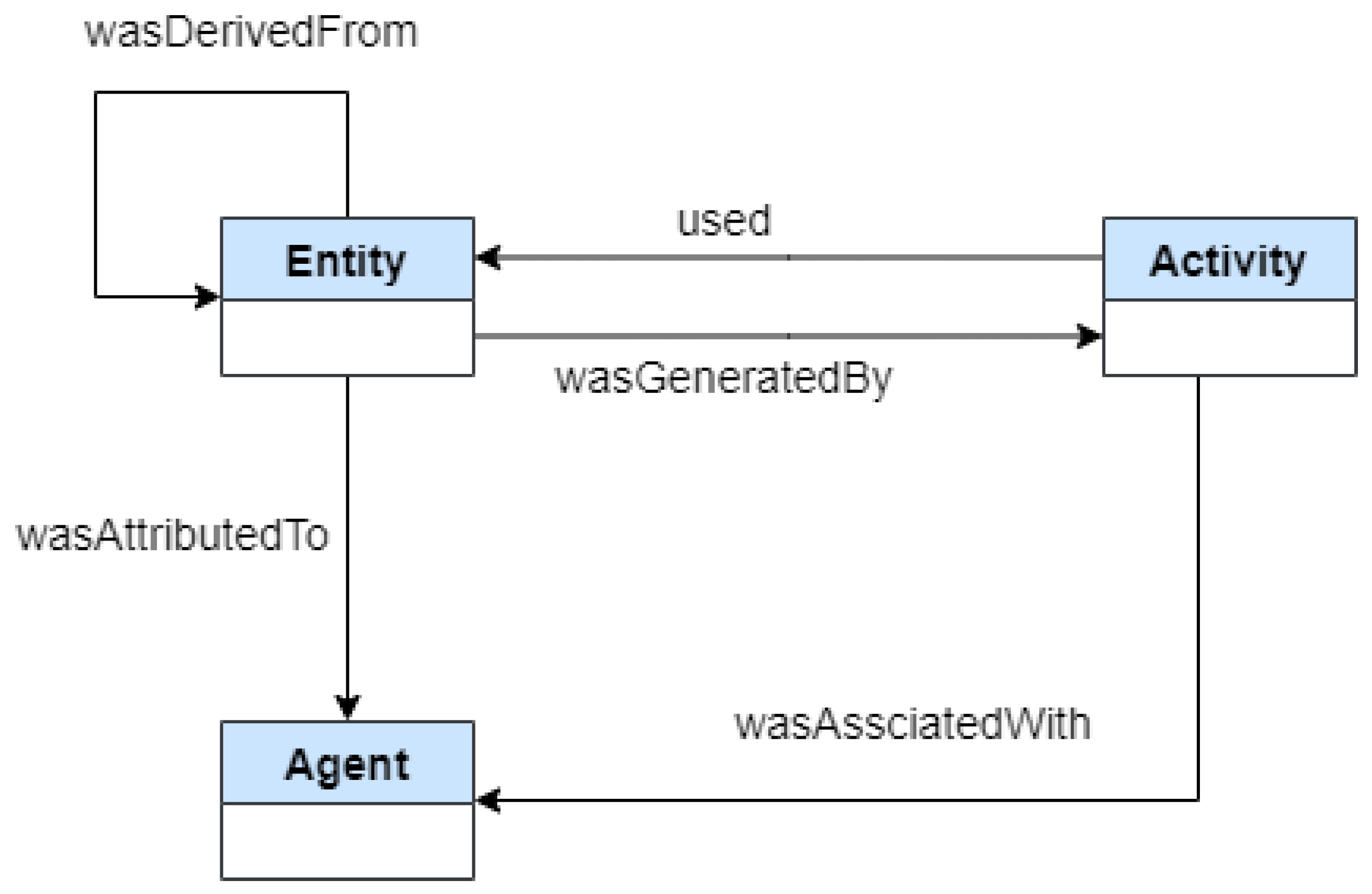
4.1. PROV Relationship Type
The PROV relationships that are supported in our prototype are illustrated in
Table 1 and by the UML diagram in
Figure 3.
The arrows point backwards in time, from the subject to the object. For example, when recording the relation: entity X was generated by activity Y, the arrow will point to the activity.
4.2. OSLC Relationship Type
Logical linking between artifacts is supported based on the OSLC specification. The type of link (i.e., the predicate used in the link triple) defines the semantics of the link and thus provides traceability between artifacts. For instance, “Model (Subject) satisfies (Predicate) a requirement (Object)”. This allows a user (or a machine) to understand the meaning of the link.
The full set of OSLC relations is available in [
50]. This paper uses a subset of these. However, it can be extended depending on the need of the stakeholder or the type of project.
Table 2 lists the OSLC relationships supported in our prototype to link artifacts across various domains.
4.3. Traceability Links Representation
Traceability links for artifacts and their relationships are represented using an N-triples [
51] format, which is a line-based, plain text serialization format for storing and transmitting data. The structure of the N-triples consists of RDF triples grouped into graphs identified with URIs: artifacts (subjects), relations (predicates), and what they belong to (objects). An example of traceability information represented as an RDF graph data model is given in
Figure 4.
5. Prototype Implementation
In this study, a prototype was implemented to validate the architectural design. A traceability server with a RESTful API was implemented in JavaScript using the NodeJS Framework. The traceability client implementation in a model-based development environment is an extension of the OpenModelica Connection Editor (OMEdit) [
52]. OMEdit is the Graphical User Interface (GUI) of OpenModelica. Previously developed components that generate traceability data in OMEdit were reused, enhanced, and integrated together with a new traceability server developed from scratch.
The traceability server is the core component of the traceability solution. It implements the traceability protocol, which allows a triplestore (which, in our implementation, is a GraphDB database) to expose resources so that trace links can be created, updated, and retrieved by the clients over HTTP. It stores the data sent via a POST message and returns a suitable response to a GET request. The requests are sent from different tools (clients), and the received data are stored in the GraphDB database. The different tools (clients) send data to an IP address (or hostname) at which the traceability server is running (which, in our implementation, can be configured in the settings). This allows multiple users to work on the project simultaneously, thus keeping the traceability links consistent and up-to-date.
Visualization and Queries
Recent research works suggest various techniques for traceability visualization to help end users to efficiently track, understand, and analyze the relationships between linked artifacts [
53,
54]. The most common visualizations of traceability links are: a matrix, lists, graphical notations, and hyperlinks. According to an empirical study by Yang Li [
55], graphs are the preferred way to obtain an overview of linked artifacts, and hyperlinks are adequate in facilitating implementation and testing tasks. Further studies [
5,
12,
56] deduced that the appropriate traceability visualization is highly dependent on the usage context and the project characteristics. Therefore, a traceability tool should support a combination of various visualization techniques since they all have advantages and disadvantages [
12].
In a matrix view, the artifacts and various relations connecting them are displayed in a two-dimensional representation in a table format. However, the use of a matrix-based approach in a large-scale project makes it difficult to visualize specific relationships due to the large number of trace links and their lack of scalability [
55]. Hence, the matrix view is not implemented due to the heterogeneity of different artifact types (requirement, design, scenario, verification model, verification report, and simulation results).
In this research work, hyperlinks, lists, and graph visualization techniques were realized by integrating the built-in GraphDB interface into our framework. In the hyperlinks view, traceability links are displayed as hyperlinks from an artifact and can be clicked to navigate to the linked artifacts. The graph-based visualization approach represents different entities (artifacts, agents, and activities) as nodes and the links as edges in a graph. Also, different types of entities are identified using specific colors. However, in the case of large amounts of data, it is less intuitive to display relationships. To make it more intuitive, the tool allows for the querying of the traceability data, which filters the set of relationships to be displayed.
To better support browsing and change impact analysis, query-based link/artifact search from the database using an RDF query language, SPARQL, was used. Some examples of queries are given below:
List all verified (Listing 1) or violated (Listing 2) requirements.
List all artifacts created by a user named “John”: Listing 3.
List all simulation results: Listing 4.
| Listing 1 List all verified requirements |
PREFIX oslc: <http://openmodelica.org/>
select ?verified_requirementswhere {
?s oslc:verifies ?verified_requirements .
?verified_requirements rdf:type oslc:Requirement .
} limit 100 |
| Listing 2 List all violated requirements |
PREFIX oslc: <http://openmodelica.org/>
select ?violated_requirementswhere {
?s oslc:violates ?violated_requirements .
?violated_requirements rdf:type oslc:Requirement .
}limit 100 |
| Listing 3 List all artifacts created by a user named “John” |
PREFIXoslc: <http://openmodelica.org/>
select ?artifacts_created_by_Johnwhere {
?artifacts_created_by_John oslc:wasAttributedTo "Agent.John" .
}limit 100 |
| Listing 4 List all simulation results |
PREFIXoslc: <http://openmodelica.org/>
select ?simulation_resultswhere {
?simulation_results rdf:type oslc:SimulationResult .
}limit 100 |
6. Use Case
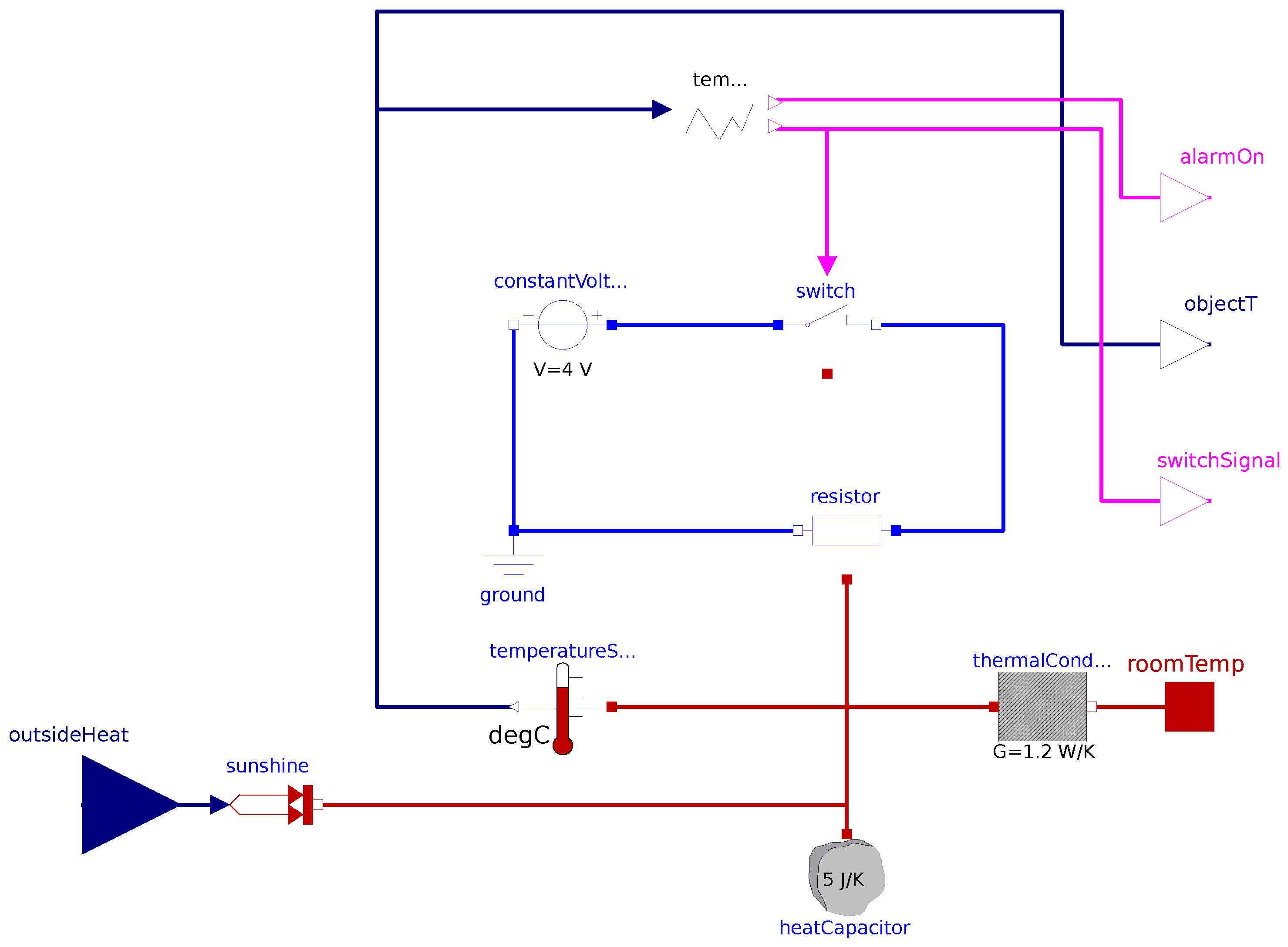
It consists of a single design alternative illustrated in
Figure 5, two scenarios to illustrate different usage patterns and the four requirements specified as follows:
- Req. 001
The element temperature should never exceed 35 degrees Celsius.
- Req. 002
To prevent system damage, once the heater is turned on/off it should not be turned off/on, respectively, for at least 3 s.
- Req. 003
After the first 2 s, the controller will keep the temperature above 21.5 degrees.
- Req. 004
If the power is lost, the controller should open the switch and sound an alarm within 2 s.
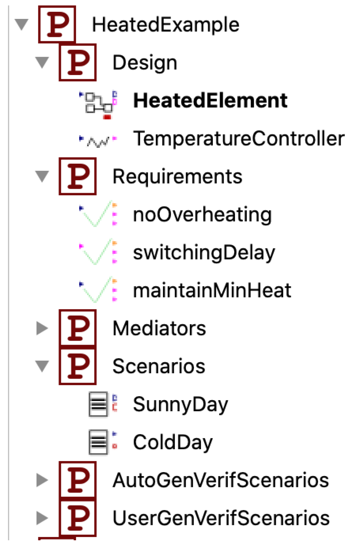
Figure 6 shows the overall structure of the package.
While building the system, when saving any of the models in OMEdit, traceability data are automatically generated, such as in
Figure 7.
When a user drags and drops a component into a model, a “used” link is generated in the traceablity data (such an example can be seen in Figure 10). For existing models that were not built using the OMEdit graphical editor, the tool queries the OpenModelica interactive compiler for all of the defined components to generate the “used” traceability links. This way we can also automatically build traceability data for existing legacy models and libraries.
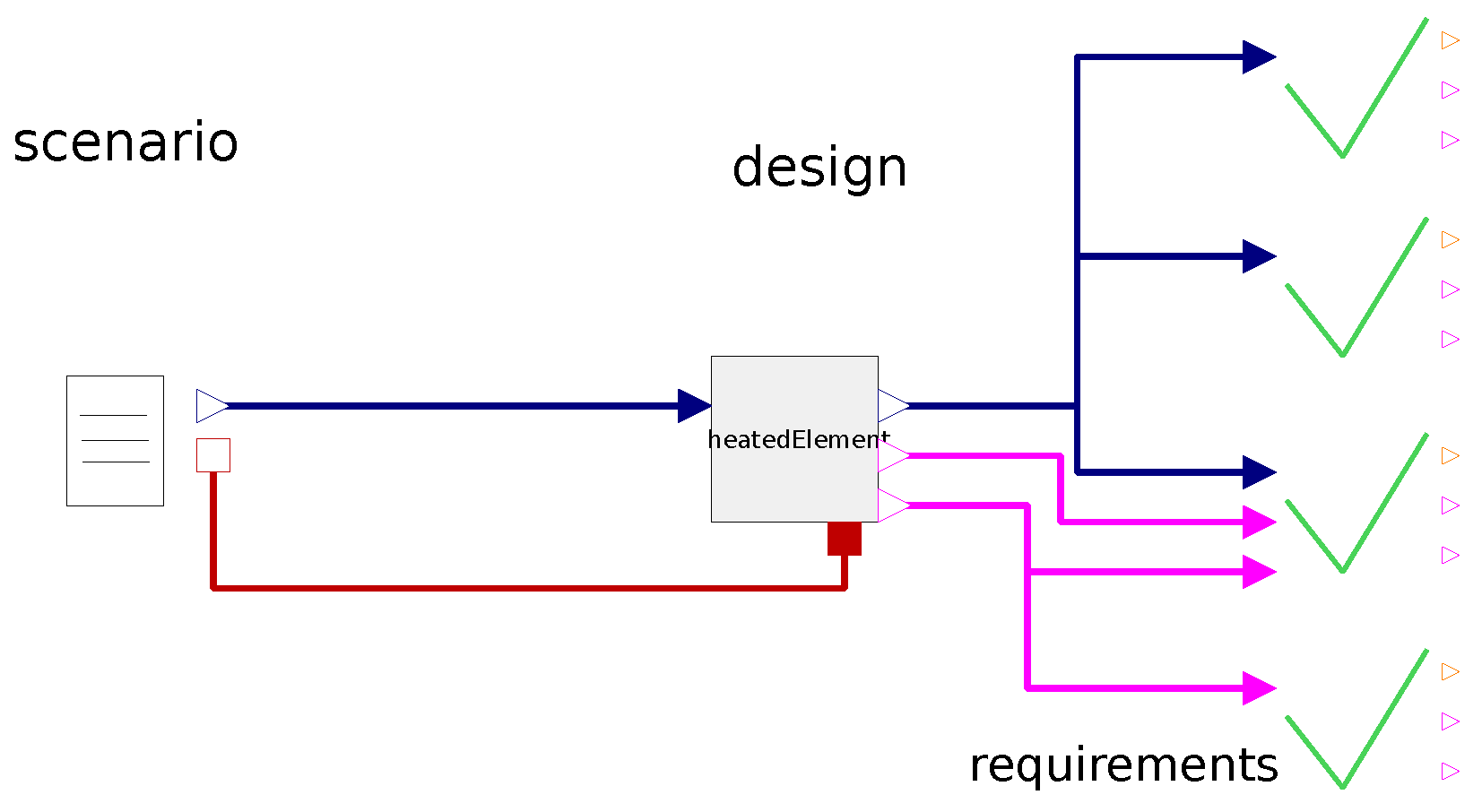
Once the different components of the system are defined, the binding algorithm implemented in OpenModelica can be used to generate all possible verification models (
Figure 8). This is done by collecting all of the possible design alternatives, scenarios, and requirements from the selected packages. For each design alternative and for each scenario, a set of all the requirements that can be verified is collected and a verification model is generated. Since in this use case, there is a single design alternative and two possible scenarios, this results in two possible combinations, one for each scenario. Every verification model includes the set of requirements for which bindings could be computed. Traceability data that links all these models are also generated automatically.
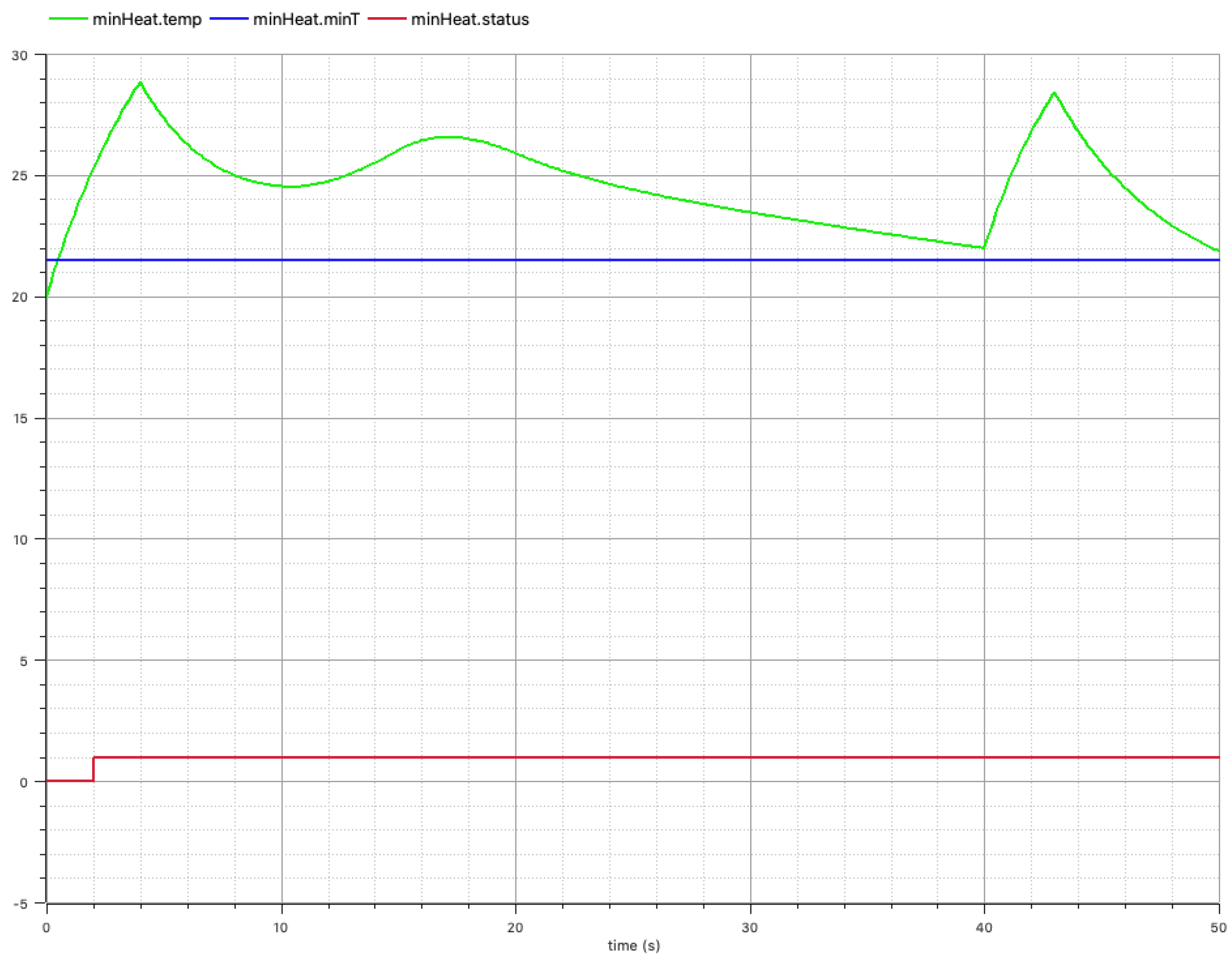
Once one of these models is simulated, requirement status values can be plotted for each requirement to verify whether they were violated during the simulation.
Figure 9 shows that
Req. 003 is fulfilled for this simulation scenario as the temperature rises above 21.5 degrees in the first 2 s, and stays above the threshold.
However, verifying requirements one by one is complicated for a large system. Moreover, when re-simulating a modified system, it should be possible to quickly detect whether or not the changes to the design or the requirement model have affected the system’s ability to fulfill the requirements. To this end, we introduce the first prototype for traceability support and visualization as shown in
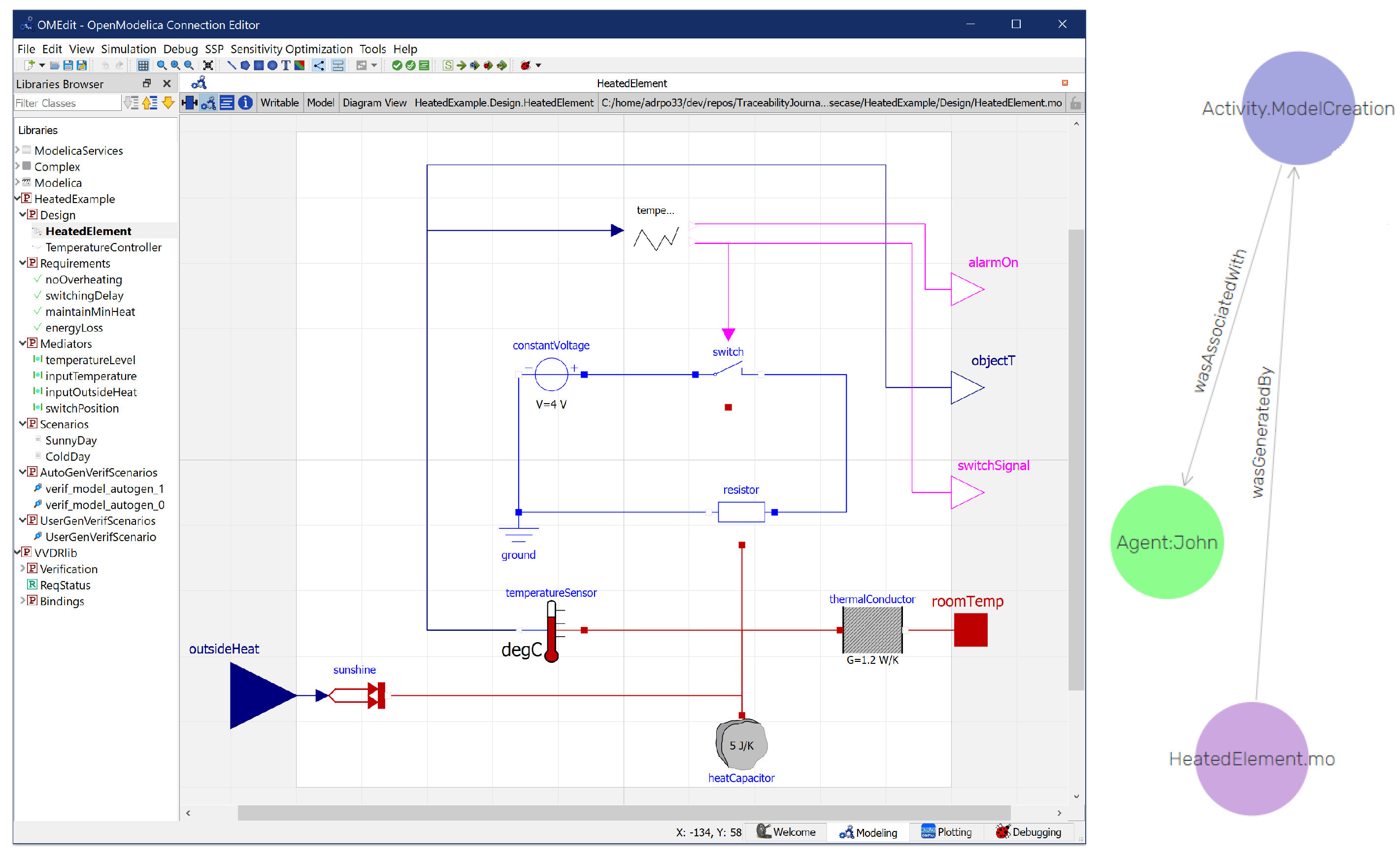
Figure 10.
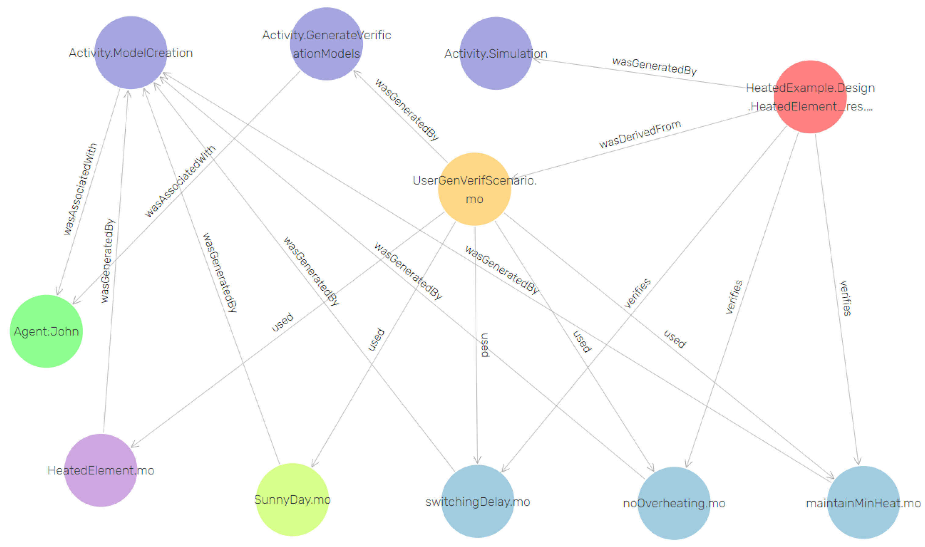
Figure 10 shows all the artifacts created for the heating system starting from the stakeholder’s requirement document, through design alternative model, down to verification results and their relationships.
All the artifacts and activities are represented by vertices connected by edges to illustrate the relationships between them. Requirement models are shown in blue, the design model is shown in violet, the scenario model is shown in lime, the verification model is shown in yellow, the simulation result is shown in red, activities (e.g., “Activity.ModelCreation”, “Activity.Simulation”, and “Activity.GenerateVerificationModel”) are shown in blue-violet, the user who performed the activity (e.g., “Agent.John”) is shown in green, and their relationships (e.g., “wasGeneratedBy”, “wasDerivedFrom”, “used”, and “verifies”) are shown with arrows. OMEdit supports the creation of the links (i.e., the PROV and OSLC triples describing the activity) automatically by generating a unique URI based on the Git commit hash for each artifact, except for links to external documents such as requirement documents in natural language.
6.1. Tracing Requirement Violations
The goal of the verification status report is to simulate all of the models in the selected package that extend the special vVDR interface VerificationModel and to produce a simulation report that will quickly allow identification of the areas of interest.
The algorithm for the generation of verification models builds a graph of the relationships between the scenarios, requirements, and design alternatives, which is then passed to the function generating the report. The report is created by collecting all the instances of the requirements for each verification model and by checking the simulation results for each instance. This information can be used to detect several types of problems:
Not all the requirements are bound. This means that one of the requirements is not applicable to the chosen design alternative. For example, a requirement is written for a heating system where the heater power can be adjusted dynamically, but in the current system design, the power is constant. This is to be expected, as the requirements are written from a specification rather than for a particular system implementation choice, but can be a sign of something missing in the design.
Not all the bound requirements are tested. If a requirement is bound but never tested it may be a sign that none of the scenarios cover the test conditions necessary for this requirement. This is the case for Req. 004, because the power was not lost in any of the scenarios. This can be a sign that parts of the behavior have not been correctly or fully tested.
A number of requirements have been violated. The report provides a list of requirement violations across scenarios. Looking into the violated requirement will bring up more details. This will provide a list of scenarios in which the requirement was violated and the time of the first violation of the requirement.
For the heated element use-case, two verification scenarios were simulated and a report was generated. For simplicity, in the rest of this section, traceability is illustrated for a single verification scenario generated for a SunnyDay.
The list of all violated requirements can be queried as follows (Listing 5):
| Listing 5 List all violated requirements |
PREFIX oslc: <http://openmodelica.org/>
select ?violated_requirements where {
?s oslc:violates ?violated_requirements .
?violated_requirements rdf:type oslc:Requirement .
} limit 100 |
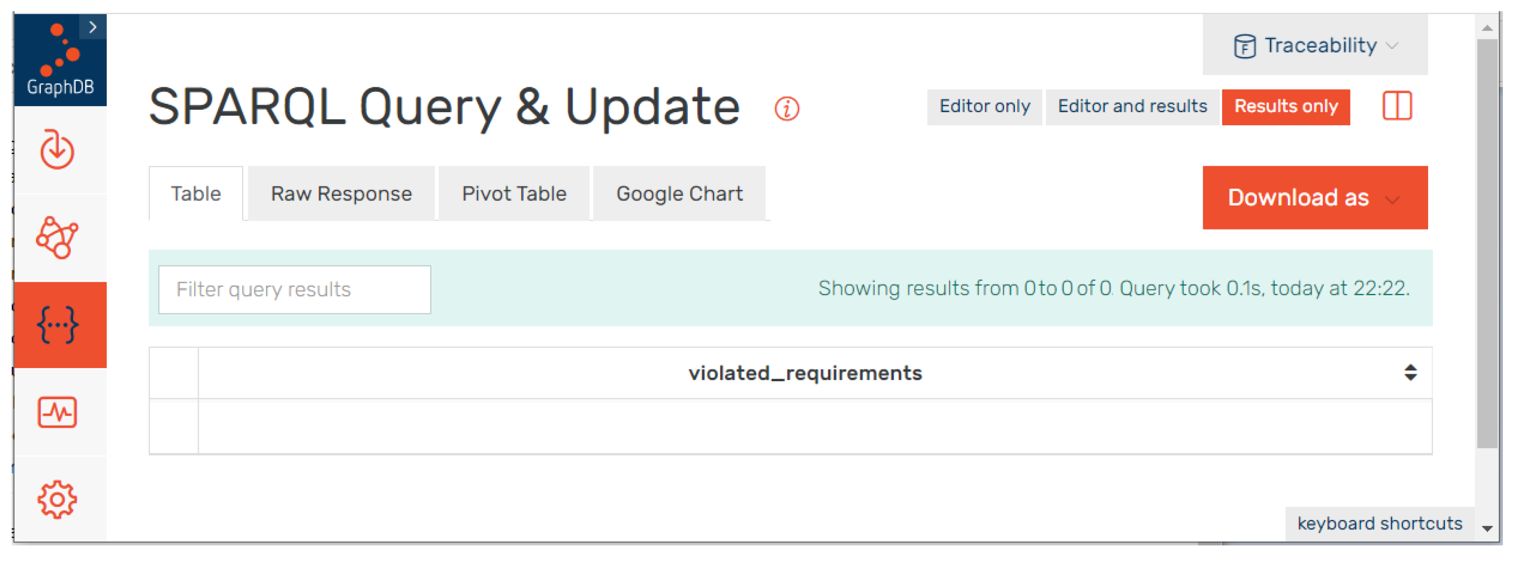
The corresponding result is visualized using hyperlinks as shown in
Figure 11. By clicking on hyperlinks, users can access the artifacts and their modifications from the central artifacts repository. The list is empty because the SunnyDay verification scenario does not violate any requirements.
6.2. Traceability and Impact Analysis
The previous section illustrates that it is possible to trace problems in a particular system design using requirements. If the modeler makes a change to the design and goes through the verification process again, some requirements might be affected (e.g., a requirement that was satisfied in all scenarios before might now be violated in some scenarios). In order to support the verification process throughout the development life cycle variant, traceability in OpenModelica can be coupled with requirement violation monitoring to track the changes that might have caused the system to violate requirements that were previously satisfied.
Because all artifacts and actions are versioned and traced, one can use the traceability information and the Git repository to provide impact analysis, i.e., what is affected (with regards to verification) by a change in: a requirement, a scenario, or a design. One could also start from two different verification reports and highlight their differences tracing back to original requirements, development, etc.
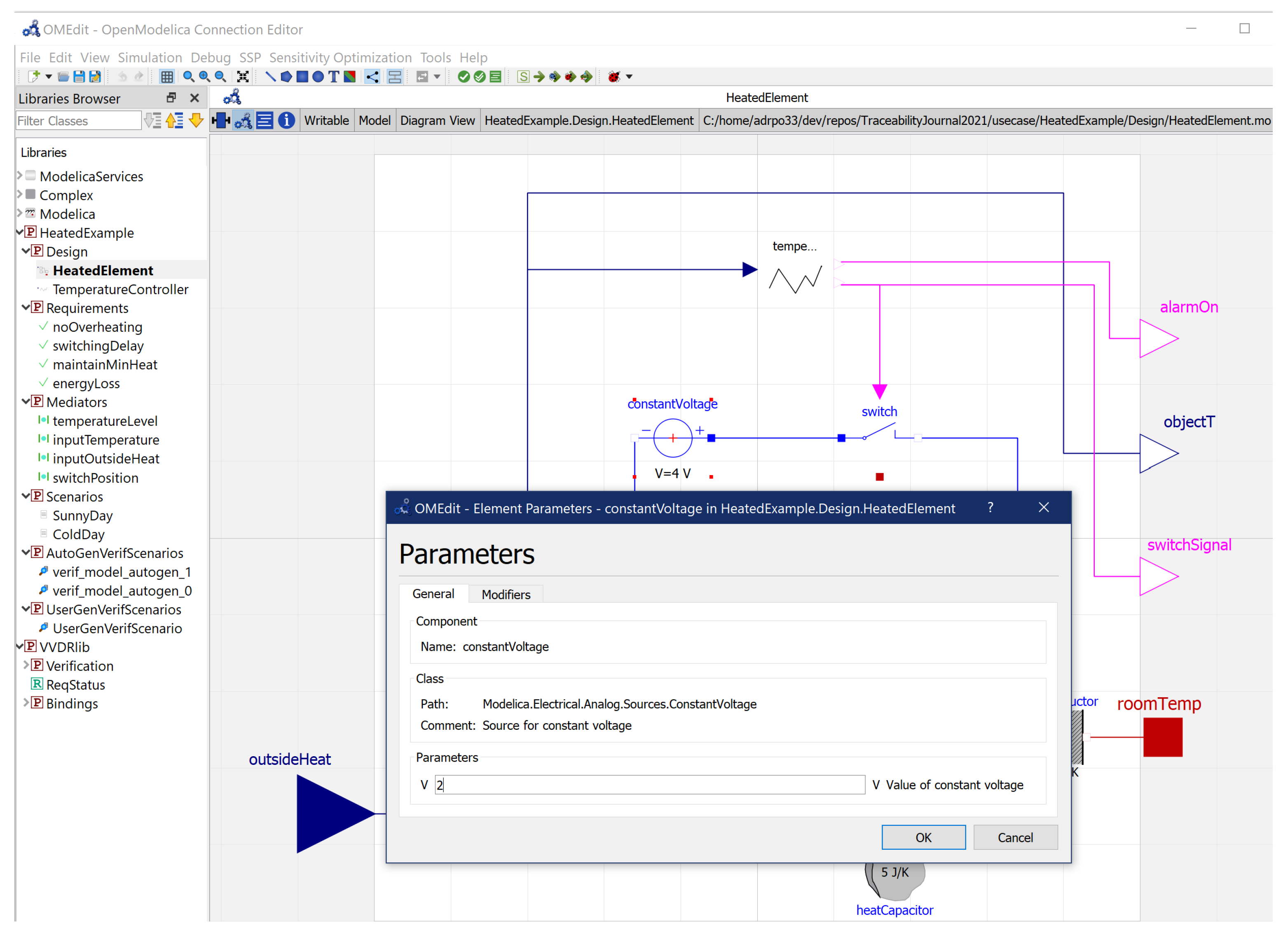
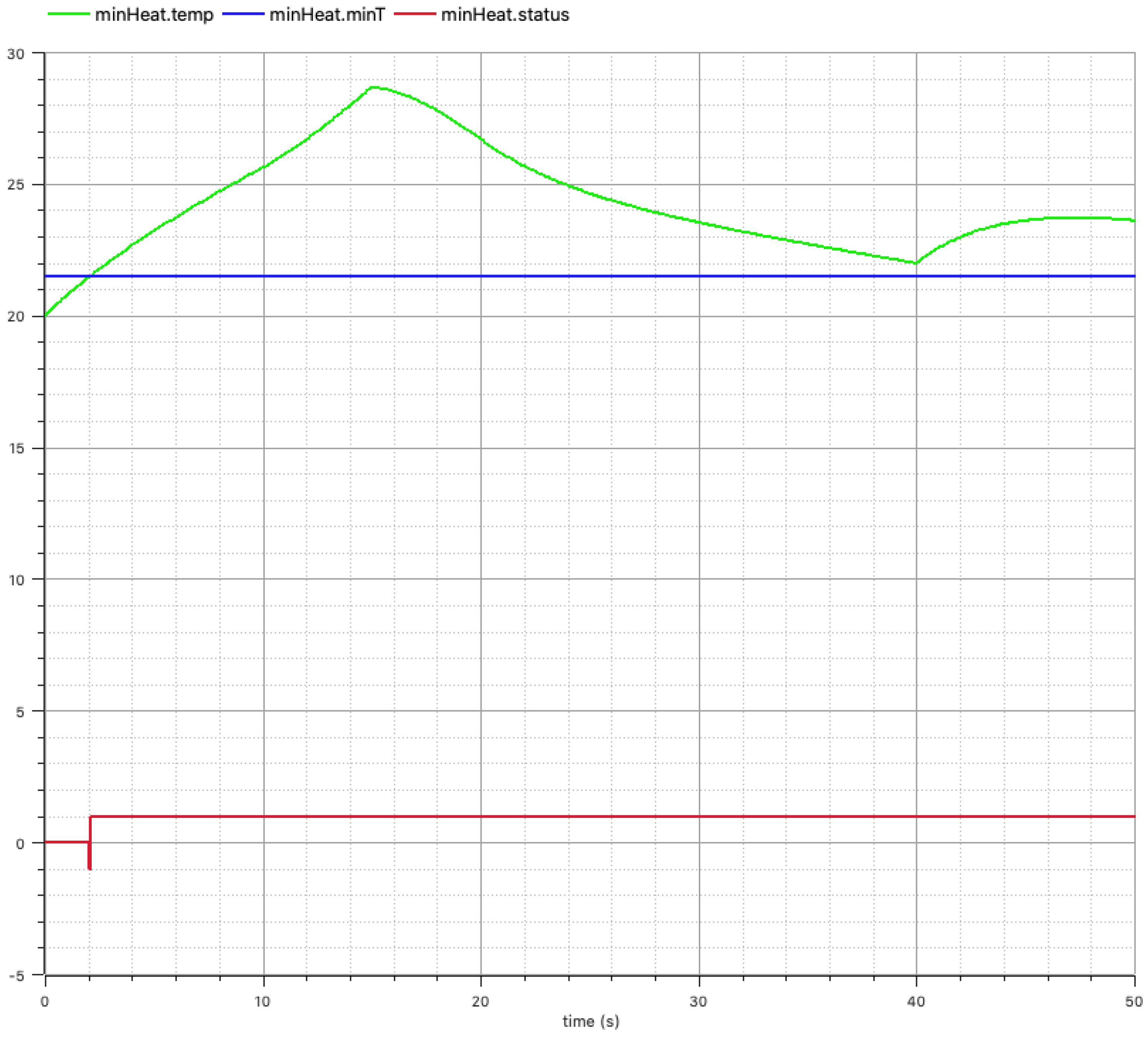
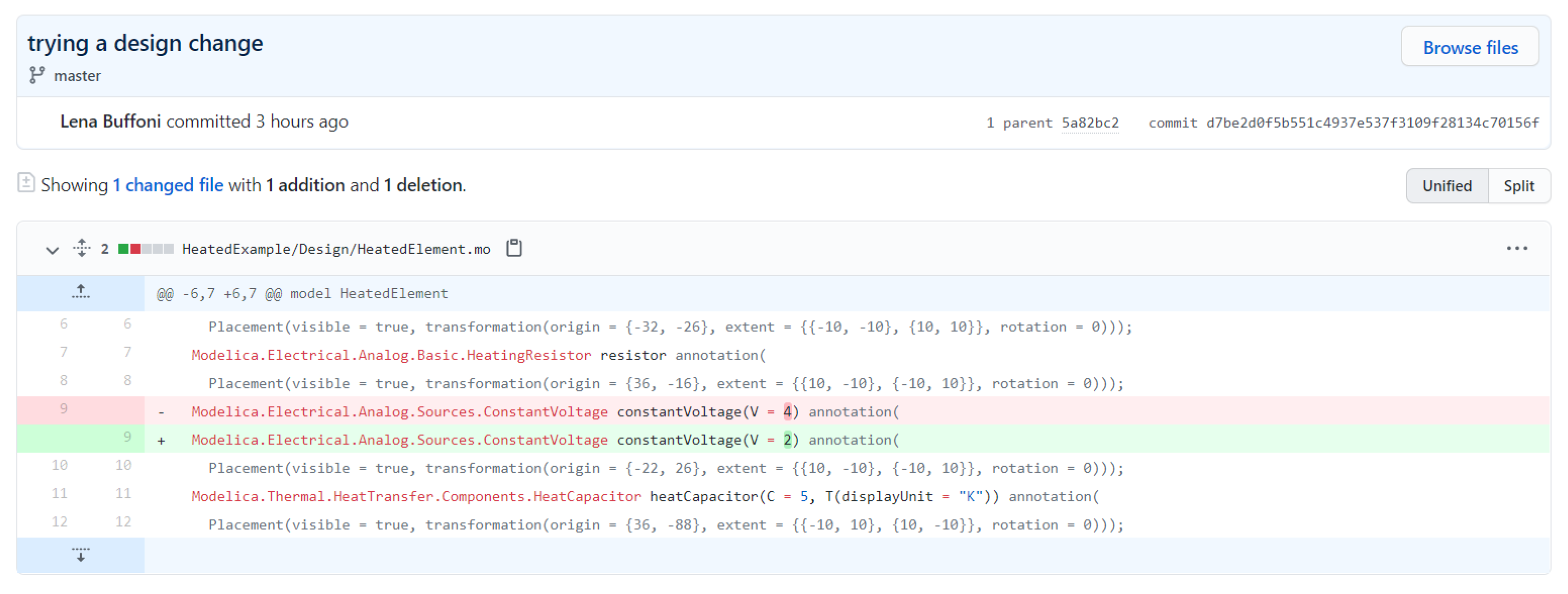
Example 1. The engineer developing the system wants to see if it is possible to halve the voltage of the heating unit and still fulfill all of the system requirements in order to produce a more cost-effective design solution. The voltage of the power source is thus changed from 4 to 2 V (see Figure 12). The question that the traceability can answer is: how will this change impact the previous verification of the requirements?
When simulating the new configuration, it should be possible to detect that while Req. 001 and Req. 002 are fulfilled for the SunnyDay scenario and Req. 004 is not applicable, Req. 003 is now violated because the power of the heating unit is insufficient.
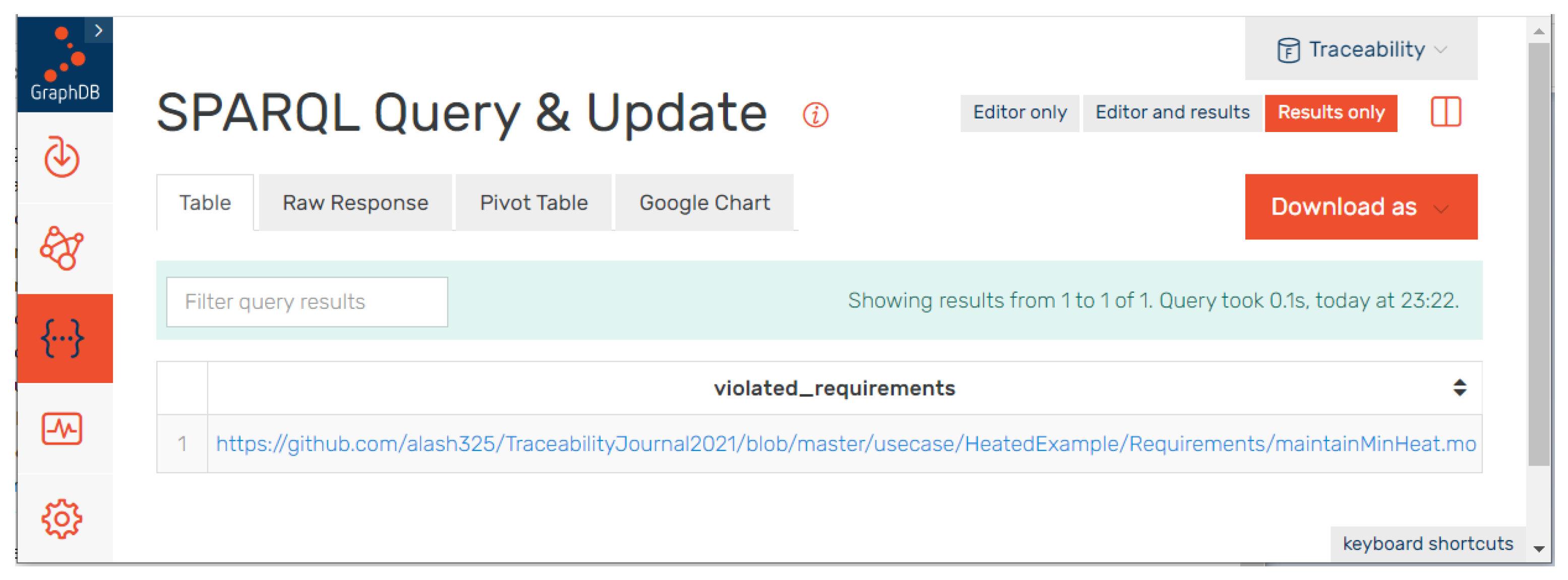
The fist step is to query for violated requirements again. This operation will identify one violated requirement (
Figure 13).
By comparing with previous results it is possible to detect that requirement
Req. 003 was previously validated but is now violated once. This can be confirmed by plotting the simulation results (
Figure 14).
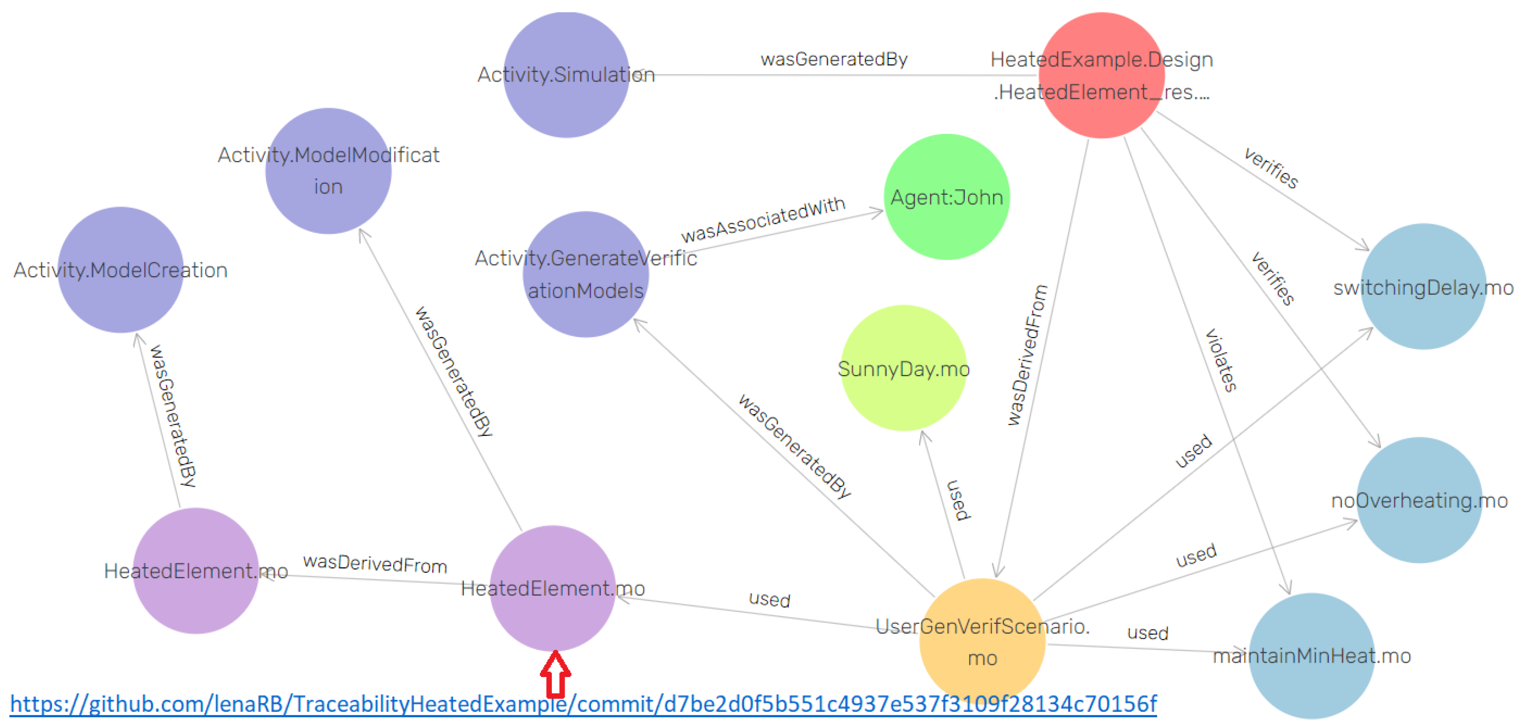
To further investigate this issue using traceability, one can start from the artifacts filtered on those that have a relation with
Req. 003, (See
Figure 15) walk the relation to the (new) verification models, and run them creating new simulation results artifacts. In the figure one can see that HeatedElement was created and then modified and used in the new UserGenVerifScenario, which produced the new result that violates requirement maintainMinHeat.
7. Related Work
Several techniques exist to support traceability among heterogeneous artifacts in model-based cyber–physical product design. However, most tools (e.g., IBM Rational DOORS Next Generation [
57], Enterprise Architect [
58], The AUTomotive Open System ARchitecture (AUTOSAR) [
59], Eclipse Capra [
60], and EMFTrace [
61]) are limited to a specific domain and problem, and lack support for automatic traceability link creation and maintenance.
IBM Rational DOORS Next Generation supports traceability between requirements. In addition, it provides an OSLC interface to link requirements with other artifacts.
Enterprise Architect provides traceability for requirement models. It links requirements to the design and implementation through tool integration.
The AUTomotive Open System ARchitecture only supports traceability for a specific type of requirements (i.e., safety-critical ones).
Eclipse Capra with EMFTrace provides tracing between different artifacts modeled in different domain-specific languages. However, trace links are created and maintained manually.
Domain specific solutions have been proposed in previous research work such as a traceability model supporting heterogeneous artifacts for the automotive domain [
62]. However, this solution only supports specific types of trace links and cannot be extended to support new traceability links or different modeling languages.
The previous research work in the INTO-CPS project [
16] supports traceability in the model-based design of CPSs between heterogeneous artifacts from different life cycle modeling languages and simulation tools through tool integration. The integration is based a standardized interface and format using OSLC, which allows artifacts from different tools to be connected to the workflow. Similarly, Amalfitano et al. [
63] developed a tool integration solution for managing traceability between Polarion ALM and MATLAB testing environments. The architecture can be extended if new tools have to be integrated with the ALM platform. This is not a trivial task however, and requires a considerable effort and may be costly especially if there are many tools that need to be integrated [
64].
In comparison with the above mentioned tools and approaches, this paper presents a traceability framework developed in an integrated virtual verification environment for modeling systems, requirements, and test cases. This is achieved with a model-driven technique where most artifacts are represented as models (with the exception of simulation results or external documents) using the same modeling language and are accessible from the same tool.
8. Conclusions and Future Work
Supporting an integrated traceability framework in model-based design environments enables different stakeholders to collaborate and to interact with heterogeneous artifacts and enables them to track changes and dependencies in the system by providing support for creating and establishing traceability links between such artifacts.
This paper presents an approach and a prototype implementation for generating traceability links throughout the development life cycle for change impact analysis in requirements verification of CPS design. A traceability software architecture was designed and implemented using a central graph database as a repository for all traceability links. Using a version control system as a central global repository for artifact management and for collaborative work involving multiple users is supported. An OSLC compliant interface as a set of RESTful services for writing and retrieving traceability information from the database was also developed.
The prototype provides automatic creation, storage, and maintenance of traceability links between artifacts created during the development of CPSs. This solution supports different artifacts of heterogeneous systems ranging from requirements models, through design models, down to simulation and verification results.
For impact analysis, support is provided for a query-based link and artifact search over the traceability data. The first version of the prototype displays a list of all verified and violated requirements in a pre-defined query using hyperlink visualization. Furthermore, users can easily query the traceability graph database directly to retrieve specific information about the links between different artifacts such as requirements, users, test results, or design using the SPARQL querying language. The combination of a pre-defined hyperlink visualization with a direct query using the SPARQL querying language provides the basic features to perform change impact analysis on design models.
However, drawing more benefits from traceability links that have been created between artifacts requires highly configurable, flexible, and scalable visualization techniques that enable users to navigate a large number of traces efficiently. To achieve this target and enhance the change impact analysis features, we aim to extend our work with new visualization options and evaluate these techniques in terms of usability.
Author Contributions
Conceptualization, A.M., A.P. and L.B.; methodology, L.B. and A.M.; software, A.M., L.B. and A.P.; validation, A.M.; investigation, A.M.; writing—original draft preparation, A.M.; writing—review and editing, A.P. and L.B.; supervision, A.P.; project administration, A.P. and L.B.; funding acquisition, A.P. and L.B. All authors have read and agreed to the published version of the manuscript.
Funding
This work has been supported by the Swedish Government has been received from the European Union in the H2020 INTO-CPS project, and by Vinnova in the ITEA OPENCPS and EMBRACE project. The OpenModelica development is supported by the Open Source Modelica Consortium.
Conflicts of Interest
The authors declare no conflict of interest. The funders had no role in the design of the study; in the collection, analyses, or interpretation of data; in the writing of the manuscript, or in the decision to publish the results.
Abbreviations
The following abbreviations are used in this manuscript:
| OSLC | Open Services for Lifecycle Collaboration |
| RDF | Resource Description Framework |
| FMI | Functional Mockup Interface |
| PROV | The Provenance Notation |
| URI | Uniform Resource Identifier |
| CPS | Cyber–Physical Systems |
| vVDR | Virtual Verification of Designs against Requirements |
| OMEdit | OpenModelica Connection Editor |
References
- Garro, A.; Tundis, A.; Bouskela, D.; Jardin, A.; Thuy, N.; Otter, M.; Buffoni, L.; Fritzson, P.; Sjölund, M.; Schamai, W.; et al. On formal cyber physical system properties modeling: A new temporal logic language and a Modelica-based solution. In Proceedings of the IEEE International Symposium on Systems Engineering (ISSE), Edinburgh, UK, 3–5 October 2016. [Google Scholar]
- Otter, M.; Thuy, N.; Bouskela, D.; Buffoni, L.; Elmqvist, H.; Fritzson, P.; Garro, A.; Jardin, A.; Olsson, H.; Payelleville, M.; et al. Formal Requirements Modeling for Simulation-Based Verification. In Proceedings of the 11th International Modelica Conference, Versailles, France, 21–23 September 2015. [Google Scholar]
- Liang, F.; Schamai, W.; Rogovchenko, O.; Sadeghi, S.; Nyberg, M.; Fritzson, P. Model-based Requirement Verification: A Case Study. In Proceedings of the 9th International Modelica Conference, Munich, Germany, 3–5 September 2012. [Google Scholar]
- David, P.; Idasiak, V.; Kratz, F. Reliability study of complex physical systems using SysML. Reliab. Eng. Syst. Saf. 2010, 95, 431–450. [Google Scholar] [CrossRef]
- Gotel, O.C.Z.; Finkelstein, A.C.W. An analysis of the requirements traceability problem. In Proceedings of the IEEE International Conference on Requirements Engineering, MColorado Springs, CO, USA, 18–21 April 1994. [Google Scholar]
- Letelier, P. A Framework for Requirements Traceability in UML-based Projects. In Proceedings of the 1st International Workshop on Traceability in Emerging Forms of Software Engineering, Edinburgh, UK, 28 September 2002. [Google Scholar]
- Lindvall, M.; Sandahl, K. Traceability Aspects of Impact Analysis in Object-Oriented Systems. J. Softw. Maint. 1998, 10, 37–57. [Google Scholar] [CrossRef]
- Bianchi, A.; Fasolino, A.R.; Visaggio, G. An exploratory case study of the maintenance effectiveness of traceability models. In Proceedings of the 8th International Workshop on Program Comprehension, Limerick, Ireland, 10–11 June 2000. [Google Scholar]
- Maletic, J.I.; Munson, E.; Marcus, A.; Nguyen, T.N. Using a Hypertext Model for Traceability Link Conformance Analysis. In Proceedings of the 2nd International Workshop on Traceability in Emerging Forms of Software Engineering, Montreal, QC, Canada, 7 October 2003. [Google Scholar]
- Olsson, T.; Grundy, J. Supporting Traceability and Inconsistency Management between Software Artifacts. In Proceedings of the 6th IASTED International Conference on Software Engineering and Applications, Cambridge, MA, USA, 4–6 November 2002. [Google Scholar]
- Kannenberg, A.; Saiedian, H. Why software requirements traceability remains a challenge. Crosstalk J. Def. Softw. Eng. 2009, 22, 14–19. [Google Scholar]
- Winkler, S.; Pilgrim, J. A survey of traceability in requirements engineering and modeldriven development. Softw. Syst. Model. (SoSyM) 2010, 9, 529–565. [Google Scholar] [CrossRef]
- Regan, G.; McCaffery, F.; McDaid, K.; Flood, D. The barriers to traceability and their potential solutions: Towards a reference framework. In Proceedings of the 38th EUROMICRO Conference on Software Engineering and Advanced Applications, Cesme, Turkey, 5–8 September 2012. [Google Scholar]
- Parizi, R.M.; Lee, S.P.; Dabbagh, M. Achievements and challenges in state-of-the-art software traceability between test and code artifacts. IEEE Trans. Reliab. 2014, 63, 913–926. [Google Scholar] [CrossRef]
- Maro, S.; Steghöfer, J.; Staron, M. Software traceability in the automotive domain: Challenges and solutions. J. Syst. Softw. 2018, 141, 85–110. [Google Scholar] [CrossRef]
- Koenig, C.; Mengist, A.; Gamble, C.; Höll, J.; Lausdahl, K.; Bokhove, T.; Brosse, E.; Möller, O.; Pop, A. Traceability in the Model-based Design of Cyber-Physical Systems. In Proceedings of the American Modelica Conference 2020, Boulder, CO, USA, 23–25 March 2020. [Google Scholar]
- Fritzson, P.; Pop, A.; Abdelhak, K.; Ashgar, A.; Bachmann, B.; Braun, W.; Bouskela, D.; Braun, R.; Buffoni, L.; Casella, F.; et al. The OpenModelica Integrated Environment for Modeling, Simulation, and Model-Based Development. Model. Identif. Control 2020, 41, 241–295. [Google Scholar] [CrossRef]
- Fritzson, P. Principles of Object Oriented Modeling and Simulation with Modelica 3.3: A Cyber-Physical Approach, 2nd ed.; Wiley IEEE Press: New York, NY, USA, 2014. [Google Scholar]
- Modelica: A Unified Objectoriented Language for Physical Systems Modeling, Language Specification Version 3.5. Available online: https://www.modelica.org/modelicalanguage (accessed on 11 March 2021).
- Functional Mock-Up Interface (FMI) Specification 2.0.2. Available online: https://fmi-standard.org (accessed on 11 March 2021).
- Blochwitz, T.; Otter, M.; Arnold, M.; Bausch, C.; Clauß, C.; Elmqvist, H.; Junghanns, A.; Mauss, J.; Monteiro, M.; Neidhold, T.; et al. The Functional Mockup Interface for Tool independent Exchange of Simulation Models. In Proceedings of the 8th International Modelica Conference, Dresden, Germany, 20–22 March 2011. [Google Scholar]
- Hevner, A.R.; March, S.T.; Park, J.; Ram, S. Design Science in Information Systems Research. MIS Q. 2004, 28, 75–105. [Google Scholar] [CrossRef]
- Wieringa, R.J. Design Science Methodology for Information Systems and Software Engineering, 1st ed.; Springer: Berlin/Heidelberg, Germany, 2014. [Google Scholar]
- Gotel, O.; Cleland-Huang, J.; Hayes, J.H.; Zisman, A.; Egyed, A.; Grünbacher, P.; Antoniol, G. The quest for Ubiquity: A roadmap for software and systems traceability research. In Proceedings of the 20th IEEE International Requirements Engineering Conference (RE), Chicago, IL, USA, 24–28 September 2012. [Google Scholar]
- Gotel, O.; Cleland-Huang, J.; Hayes, J.H.; Zisman, A.; Egyed, A.; Grünbacher, P.; Dekhtyar, A.; Antoniol, G.; Maletic, J. The Grand Challenge of Traceability (v1.0). In Software and Systems Traceability; Cleland-Huang, J., Gotel, O., Zisman, A., Eds.; Springer: London, UK, 2012; pp. 343–409. [Google Scholar]
- Egyed, A.; Biffl, S.; Heindl, M.; Grünbacher, P. A Value-Based Approach for Understanding Cost-Benefit Trade-Offs during Automated Software Traceability. In Proceedings of the 3rd International Workshop on Traceability in Emerging Forms of Software Engineering, Long Beach, CA, USA, 7–11 November 2005. [Google Scholar]
- Galvão, I.; Goknil, A. Survey of Traceability Approaches in Model-Driven Engineering. In Proceedings of the 11th IEEE International Enterprise Distributed Object Computing Conference (EDOC 2007), Annapolis, MD, USA, 15–19 October 2007. [Google Scholar]
- Pavković, N.; Bojčetić, N.; Franić, L.; Marjanović, D. Case Studies to Explore Indexing Issues in Product design traceability framework. In Proceedings of the ICED 11—18th International Conference on Engineering Design-Impacting Society through Engineering Design, Copenhagen, Denmark, 15–18 August 2011; Volume 6. [Google Scholar]
- Königs, S.F.; Beier, G.; Figge, A.; Stark, R. Traceability in Systems Engineering—Review of industrial practices, state-of-the-art technologies and new research solutions. Adv. Eng. Inform. 2012, 26, 924–940. [Google Scholar] [CrossRef]
- Arkley, P.; Riddle, S.; Brookes, T. Tailoring Traceability Information to Business Needs. In Proceedings of the 14th IEEE International Requirements Engineering Conference (RE’06), Minneapolis/St. Paul, MN, USA, 11–15 September 2006. [Google Scholar]
- Cleland-Huang, J.; Gotel, O.C.Z.; Hayes, J.H.; Mäder, P.; Andrea, Z. Software Traceability: Trends and Future Directions. In Proceedings of the Future of Software Engineering, Hyderabad, India, 31 May–7 June 2014. [Google Scholar]
- Balasubramania, R. Factors Influencing Requirements Traceability Practice. Commun. ACM 1998, 41, 37–44. [Google Scholar]
- Mäder, P.; Jones, P.L.; Zhang, Y.; Cleland-Huang, J. Strategic Traceability for Safety-Critical Projects. IEEE Softw. 2013, 30, 58–66. [Google Scholar] [CrossRef]
- Spanoudakis, G.; Zisman, A. Software traceability: A roadmap. Handb. Softw. Eng. Knowl. Eng. 2005, 3, 395–428. [Google Scholar]
- The INCOSE Systems Engineering Vision 2020. Available online: http://www.omgwiki.org/MBSE/doku.php (accessed on 13 January 2021).
- Estefan, J.A. A Survey of Candidate Model-Based Systems Engineering (MBSE) Methodologies; rev. B, INCOSE. INCOSE-TD-2007-003-02; International Council on Systems Engineering: Seattle, WA, USA, 2015. [Google Scholar]
- System Modeling Language (SysML). Available online: https://www.omg.org/spec/SysML/ (accessed on 13 January 2021).
- Unified Modeling Language (UML). Available online: https://www.omg.org/spec/UML/ (accessed on 13 January 2021).
- Schamai, W. Modelica Modeling Language (ModelicaML) a UML Profile for Modelica; Technical Report; Linköping University Electronic Press: Linköping, Sweden, 2009. [Google Scholar]
- Schamai, W.; Fritzson, P.; Paredis, C.; Pop, A. Towards Unified System Modeling and Simulation with ModelicaML Modeling of Executable Behavior Using Graphical Notations. In Proceedings of the 7th International Modelica Conference, Como, Italy, 20–22 September 2009. [Google Scholar]
- Schamai, W. Model-Based Verification of Dynamic System Behavior against Requirements: Method, Language, and Tool. Ph.D. Thesis, Department of Computer and Information Science, Linköping University, Linköping, Sweden, 2013. No. 1547. [Google Scholar]
- Buffoni, L.; Fritzson, P. Expressing Requirements in Modelica. In Proceedings of the Scandinavian Conference on Modeling and Simulation), Aalborg, Denmark, 21–22 October 2014. [Google Scholar]
- Schamai, W.; Buffoni, L.; Albarello, N.; De Miranda, P.F.; Fritzson, P. An Aeronautic Case Study for Requirement Formalization and Automated Model Composition in Modelica. In Proceedings of the 11th International Modelica Conference, Palais des Congrès de Versailles, Versailles, France, 21–23 September 2015. [Google Scholar]
- Schamai, W.; Helle, P.; Fritzson, P.; Paredis, C. Virtual verification of system designs against system requirements. In Proceedings of the 2010 International Conference on Models in Software Engineering, Oslo, Norway, 3–8 October 2010; Springer: Berlin/Heidelberg, Germany, 2010. [Google Scholar]
- Open Services for Lifecycle Collaboration. Available online: http://openservices.net/ (accessed on 13 January 2021).
- Richardson, L.; Ruby, S. RESTful Web Services, 1st ed.; OŔeilly: Boston, MA, USA, 2007. [Google Scholar]
- Heath, T.; Bizer, C. Linked Data: Evolving the Web into a Global Data Space. Synth. Lect. Semant. Web Theory Technol. 2011, 1, 1–136. [Google Scholar] [CrossRef]
- RDF Primer. Available online: https://www.w3.org/TR/2004/REC-rdf-primer-20040210/ (accessed on 13 January 2021).
- PROV-N: The Provenance Notation. Available online: https://www.w3.org/TR/prov-n/ (accessed on 13 January 2021).
- OSLC Relationships. Available online: https://archive.open-services.net/bin/view/Main/RmSpecificationV2?rev=46 (accessed on 13 January 2021).
- N-Triples-A Line-Based Syntax for an RDF Graph. Available online: https://www.w3.org/TR/n-triples/ (accessed on 13 January 2021).
- Asghar, S.A.; Tariq, S.; Torabzadeh-Tari, M.; Fritzson, P.; Pop, A.; Sjölund, M.; Vasaiely, P.; Schamai, W. An Open Source Modelica Graphic Editor Integrated with Electronic Notebooks and Interactive Simulation. In Proceedings of the 8th International Modelica Conference, Dresden, Germany, 20–22 March 2011. [Google Scholar]
- Duan, C.; Cleland-Huang, J. Visualization and Analysis in Automated Trace Retrieval. In Proceedings of the First International Workshop on Requirements Engineering Visualization, Minneapolis, MN, USA, 11 September 2006. [Google Scholar]
- Heim, P.; Lohmann, S.; Lauenroth, K.; Ziegler, J. Graph-based Visualization of Requirements Relationships. In Proceedings of the 2008 Requirements Engineering Visualization, Barcelona, Spain, 8 September 2008. [Google Scholar]
- Li, Y.; Maalej, W. Which traceability visualization is suitable in this context? a comparative study. In Proceedings of the 18th International Conference on Requirements Engineering Foundation for Software Quality, Essen, Germany, 19–22 March 2012; Springer: Berlin/Heidelberg, Germany, 2012. [Google Scholar]
- Winkler, S. On Usability in Requirements Trace Visualizations. In Proceedings of the 2008 Requirements Engineering Visualization, Barcelona, Spain, 8 September 2008. [Google Scholar]
- Rational DOORS Next Generation. Available online: https://www.ibm.com/us-en?lnk=m (accessed on 13 January 2021).
- Enterprise Architect. Available online: https://sparxsystems.com/ (accessed on 13 January 2021).
- The AUTomotive Open System ARchitecture (AUTOSAR). Available online: https://www.autosar.org/ (accessed on 13 January 2021).
- Maro, S.; Steghöfer, J. Capra: A configurable and extendable traceability management tools. In Proceedings of the 2016 IEEE 24th International Requirements Engineering Conference (RE), Beijing, China, 12–16 September 2016. [Google Scholar]
- Bode, S.; Lehnert, S.; Riebisch, M. Comprehensive model integration for dependency identification with emftrace. In Proceedings of the First International Workshop on Model-Driven Software Migration (MDSM 2011) and the Fifth International Workshop on Software Quality and Maintainability (SQM 2011), Oldenburg, Germany, 1 March 2011. [Google Scholar]
- Dang, H.L.; Dubois, H.; Gerard, S. Towards a traceability model in a MARTE-based methodology for real-time embedded systems. Innov. Syst. Softw. Eng. 2008, 4, 189–193. [Google Scholar] [CrossRef]
- Amalfitano, D.; Simone, V.D.; Maietta, R.R.; Scala, S.; Fasolino, A.R. Using tool integration for improving traceability management testing processes: An automotive industrial experience. J. Softw. Evol. Process 2019, 31, e2171. [Google Scholar] [CrossRef]
- Maro, S.; Anjorin, A.; Wohlrab, R.; Steghöfer, J.P. Traceability maintenance: Factors and guidelines. In Proceedings of the 31st IEEE/ACM International Conference on Automated Software Engineering, Singapore, 3–7 September 2016. [Google Scholar]
| Publisher’s Note: MDPI stays neutral with regard to jurisdictional claims in published maps and institutional affiliations. |
© 2021 by the authors. Licensee MDPI, Basel, Switzerland. This article is an open access article distributed under the terms and conditions of the Creative Commons Attribution (CC BY) license (https://creativecommons.org/licenses/by/4.0/).


