Article

Investigation on Thermal Resistance and Capacitance Characteristics of a Highly Integrated Power Control Unit Module

1
College of Electrical Engineering, Zhejiang University, Hangzhou 310027, China
2
Hangzhou Global Scientific and Technological Innovation Center, Zhejiang University, Hangzhou 311200, China
*
Author to whom correspondence should be addressed.
Electronics 2021, 10(8), 958; https://doi.org/10.3390/electronics10080958
Submission received: 6 March 2021 / Revised: 11 April 2021 / Accepted: 12 April 2021 / Published: 16 April 2021
(This article belongs to the Section Electrical and Autonomous Vehicles)

Abstract

:
With the increasing integration density of power control unit (PCU) modules, more functional power converter units are integrated into a single module for applications in electric vehicles or hybrid electric vehicles (EVs/HEVs). Different types of power dies with different footprints are usually placed closely together. Due to the constraints from the placement of power dies and liquid cooling schemes, heat-flow paths from the junction to coolant are possibly inconsistent for power dies, resulting in different thermal resistance and capacitance (RC) characteristics of power dies. This presents a critical challenge for optimal liquid cooling at a low cost. In this paper, a highly integrated PCU module is developed for application in EVs/HEVs. The underlying mechanism of the inconsistent RC characteristics of power dies for the developed PCU module is revealed by experiments and simulations. It is found that the matching placement design of power dies with a heat sink structure and liquid cooler, as well as a liquid cooling scheme, can alleviate the inconsistent RC characteristics of power dies in highly integrated PCU modules. The findings in this paper provide valuable guidance for the design of highly integrated PCU modules.

1. Introduction

High-density integration has become a mainstream trend in the development of power control unit (PCU) modules for electric vehicles or hybrid electric vehicles (EVs/HEVs) [1,2,3]. Highly integrated PCU modules aim at integrating more functional power converter units into a single power module while taking up the smallest possible space. In the PCU modules of the Chevrolet Volt and Cadillac CT6, the power converter units, such as the charger and inverter, are integrated into a single module [4,5]. In a PCU module of a Toyota fuel electric vehicle, the power converter units, such as boost, power generation and motor drives, are integrated into a single module [6].
The integration designs of a better heat dissipation scheme and smaller thermal resistance, as well as a smaller difference in thermal resistance, are becoming the core of the thermal design of highly integrated PCU modules [7,8,9,10]. There are extensive research works on the thermal design of PCU modules, such as the double-side heat dissipation design [11,12,13,14], the power card design for optimal liquid cooling [15] by Toyota, and the calculation method for optimal control parameters of liquid cooling of a highly integrated PCU module [16].
In addition, since the heat sink structure dominates the heat-flow paths of power dies inside a PCU module, the optimal design of heat sink structures becomes an important part of the thermal design of a PCU module. There are many types of structural designs for heat sink in PCU modules, including microchannels, pin-fin and strip-fin structures. By introducing these structures into a heat sink, the contact area between the heat sink and the coolant can be increased and the flow efficiency of coolant in the fluid space of the liquid cooler can also be increased.
Different shapes of pin-fin have been investigated [17], which showed that square shaped pin-fins can realize an optimal trade-off between cooling efficiency and pressure drop in the design of a liquid cooler. In order to achieve better cooling performance, various heat sink designs with straight cooling channels, wavy-shaped fins, as well as rectangular pin-shaped fins have been evaluated for automotive inverters [18]. It was found that the heat sink with rectangular pins can alleviate the thermal gradient at the surface of the heat sink by carefully placing the pins and dividing the coolant flow to the three power modules in a more uniform way.
Heat sinks with a pin-fin structure involve a simple manufacturing process, low pressure drops and large coolant flows. However, the temperature gradient of pin-fin structures is higher than that of microchannels. A microchannel design provides a larger contact surface area and achieves better cooling for power modules [19,20,21]. In addition, a two-phase cooling scheme [22,23,24,25] can also be used to enhanced heat dissipation in power modules. Two-phase cooling utilizes the phase change of liquid coolant to absorb heat, resulting in a much higher cooling efficiency [26].
The thermal integration design of PCU modules is evaluated by the RC characteristics of heat-flow paths of power dies. However, most previous works mainly focused on the overall heat dissipation efficiency or smaller thermal resistances. Research work on minimizing the difference in thermal resistance for different power dies in highly integrated PCU modules is rarely reported.
In a highly integrated PCU module, the current ratings of power converter units are possibly different and the types and parallel number of power dies in various units of a power converter are also different from each other. The placement of power dies is easily constrained by the spatial location of the circuit interface between various components and the overall architecture of the electrical control system. In addition, the design of a heat dissipation structure and fluid space inside a liquid cooler may also have additional impacts on the RC characteristics of different power dies. In the thermal design of a highly integrated PCU module, the placement of power dies and the structure of a liquid cooler, as well as the liquid cooling scheme can be independently optimized to improve the RC characteristics of power dies. However, it is challenging to implement such individual optimizations into the thermal design of highly integrated PCU modules. As a result, the inconsistent RC characteristics of power dies are likely to exist in highly integrated PCU modules. Hence, high-density integration presents a critical challenge in the thermal design of PCU modules for EV/HEV applications.
It is of significance to understand the underlying mechanism of the distinct RC characteristics of power dies in highly integrated PCU modules. It is valuable to minimize the discrepancies in the RC characteristics of power dies, which is particularly important to the high-density integration of PCU modules. It is crucial to realize the liquid cooling scheme of highly integrated PCU module at a low cost.
In this work, a highly integrated PCU module has been developed. The underlying mechanisms of the inconsistent RC characteristics of power dies is revealed by experiments and simulations. The paper is organized as follows. The developed PCU module and test platform of the RC characteristics are introduced in Section 2. The experimental results of the inconsistent RC characteristics of power dies are presented in Section 3. The experimental results are discussed as are the underlying mechanisms in Section 4. Conclusions are drawn in Section 5.

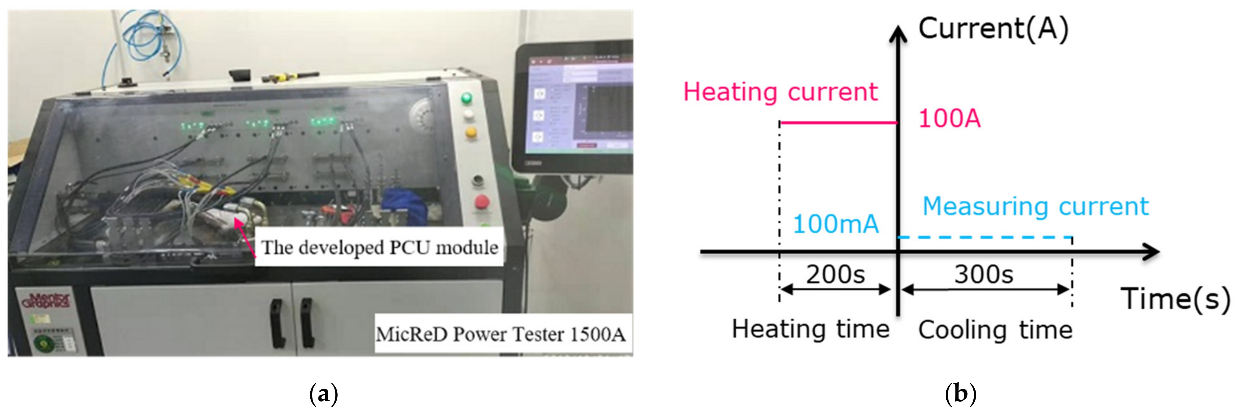
2. The Highly Integrated PCU Module and Test Platform for RC Characteristics

A photo of the developed PCU module is shown in Figure 1. Three functional units (power converter, boost converter, power generator converter and motor drives) are integrated onto a single liquid cooler. The current ratings for the units of the boost converter, power generator and motor drives are 300 A, 450 A and 600 A, respectively. The footprint area of these power converter units is different. In addition, the inlet and outlet for coolant are both placed on the right side of the PCU module.
The circuit topology of the developed PCU module is shown in Figure 2. The power converter unit in the blue box is the boost converter (boost unit), the ones in the green box and red box are the power generator (GM_1 unit) and motor drives (GM_2 unit), respectively. There are three phases in each power converter unit. The circuit topology of each phase is a half-bridge configuration. There are two types of power dies on the upper-side or lower-side of each phase, which are the insulated gate bipolar transistor (IGBT) and the anti-parallel fast recovery diode (FRD) dies, respectively.
The 1st phase is the rightmost phase, the 2nd phase is the middle phase and the 3rd phase is the leftmost phase in each power converter unit. For example, the 1st phase of the GM_2 unit consists of I1 and I2 IGBT dies and d1 and d2 FRD dies, the 2nd phase of the GM_1 unit consists of I9 and I10 IGBT dies and d9 and d10 FRD dies, and the 3rd phase of the boost unit consist of I17 and I8 IGBT dies and d17 and d18 FRD dies.
Due to these designs, as shown in Figure 1 and Figure 2, the coolant in the fluid space of the liquid cooler flows from the area corresponding to the 1st phase to that of the 3rd phase on the upper side, whereas it flows from the area relating to the 3rd phase to that of the 1st phase on the lower side.
There are many indicators of RC characteristics for power dies, such as a thermal impedance curve, pulse thermal resistance, cumulative structure function (SF), RC model and junction-to-liquid resistance (Rth,JL). SF is one of the most important indicators for RC characteristics, which is the thermal resistance and capacitance (RC) map of the heat-flow paths for measured power dies. In a RC map, the cumulative thermal capacitance (Cth) is plotted as a function of the cumulative thermal resistance (Rth) for the heat-flow path, which is measured from the point of excitation toward the ambient. The distribution of thermal resistances and capacitances for each layer structure of the heat-flow path along the heat-flow direction can be distinguished from SF. Based on the SF, the Rth,JL for the measured power dies can also be acquired. Rth,JL is the cumulative thermal resistance of heat-flow paths from the power die (excitation point) to the cooling liquid (ambient). It describes the temperature difference along a heat-flow path from the measured power dies to the cooling liquid when the measured power dies have a power loss of 1 W.
As the main purpose in thermal design of highly integrated PCU modules, it is important to reduce the Rth,JL for power dies while minimizing the difference in Rth,JL among the power dies. It is particularly important to minimize the difference in Rth,JL between the upper- and lower-sides of power dies within a single unit of a power converter, as it is an effective approach to avoid overheating local power dies, and has a low cost under a same operation conditions.
The Rth,JL of power dies is measured using a MicReD Power Tester 1500 A, which is shown in Figure 3a. During measurement of thermal resistance, the heating and measuring current for power dies are 100 A and 100 mA, respectively. Figure 3b shows the testing conditions of the time intervals for the heating and cooling processes. A heating current of 100 A is applied to the measured power dies for 200 s; the temperature rise in the power dies is sufficient for the subsequent analysis of thermal resistance. It is also reasonable to compare the RC characteristics of power dies under the same test conditions. When the heating current is switched off, the measuring current is immediately applied to the measured power dies to acquire the temperature response of the measured power dies in the cooling process. A measuring current of 100 mA is also the optimal value from many trials. A larger or smaller value may affect the accuracy of the K-factor, thereby reducing the accuracy of the structure function. The duration of the cooling process is set to 300 s, which allows the heated power dies to return to ambient temperature under the conditions of the present cooling scheme. During the heating and cooling processes in the experiments, the volume flow rate of coolant (65% ethylene glycol solution) was set to be 10 L/min. These cooling parameters are consistent with actual operational parameters of cooling systems for the developed PCU module.
Before measuring the temperature response of power dies in the cooling process, the K-factor of the measured power dies must be calculated using a MicReD Power Tester 1500 A. The K-factor is a ratio that describes the linear relationship between the junction temperature of the power dies and the temperature-sensitive electrical performance parameter (TSEP) of the power dies. In experiments, the adopted TESP for the IGBT and FRD dies was the saturation voltage of IGBT and forward voltage of FRD, respectively.
Based on the K-factor of the power dies, the curve of temperature response in the cooling process could be recorded by applying a measuring current of 100 mA to the measured power dies on a MicReD Power Tester 1500 A. Then, the curve of the temperature response was analyzed using the post-processing software T3Ster Master. Eventually, the indicators of RC characteristics, such as SF and Rth,JL were obtained. The RC characteristics in this paper mainly refer to the trend of changes in the difference of Rth,JL (or SF) for power dies between the upper and lower sides, from the 1st phase to the 3rd phase.

3. Experimental Results

3.1. RC Characterisics of IGBT Dies

Figure 4 shows the SFs of the heat-flow paths of the measured IGBT dies, where the horizontal axis represents the cumulative thermal resistance (Rth) of the heat-flow path from the measured power dies toward the cooling liquid, and the vertical axis represents the cumulative thermal capacitance (Cth) of the heat-flow path from the measured power dies toward the cooling liquid.
For the IGBT dies of each phase, the SF curve on the upper side was basically the same as that of lower side in the first half of RC map, and it was different from that of the lower side in the second half of the RC map.
As shown in Figure 4, some SF curves of the upper side do not completely overlap with those of the lower side in the first half of the RC map. This is mainly related to the deviation in the manufacturing process of the PCU module, such as the deviation between the actual position of power dies and the design position, and the power dies and the heat sink are also likely to have different degrees of inclination after power dies are soldered, so that the actual structure of the solder layer between the upper and lower sides are not entirely consistent. These deviations are the main reasons why they cannot completely overlap.
Compared with the insignificant difference in the SF curves in first half of the RC map, the SF curves in the second half of the RC map for the power dies of the upper side are significantly different from those of the lower side. Due to this significant difference of SF curves in the second half of RC map, the Rth,JL of the upper side is different from that of the lower side.
The difference in Rth,JL between the upper and lower side appears to be an inconsistent trend of change from the 1st phase to the 3rd phase among the three units of the power converter. For units of GM_2 and GM_1, the difference of Rth,JL between the upper and lower sides changes insignificantly from the 1st phase to the 3rd phase. For the boost unit, it rises significantly from the 1st phase to the 3rd phase. The difference in Rth,JL in the 1st phase is 0.008 °C/W, as shown by the blue marks in Figure 4a, and it rises to 0.038 °C/W in the 3rd phase, as shown in Figure 4c. As a result, the difference in Rth,JL between the upper and lower side in the 3rd phase of the boost unit is higher than that of the GM_1 and GM_2 units.

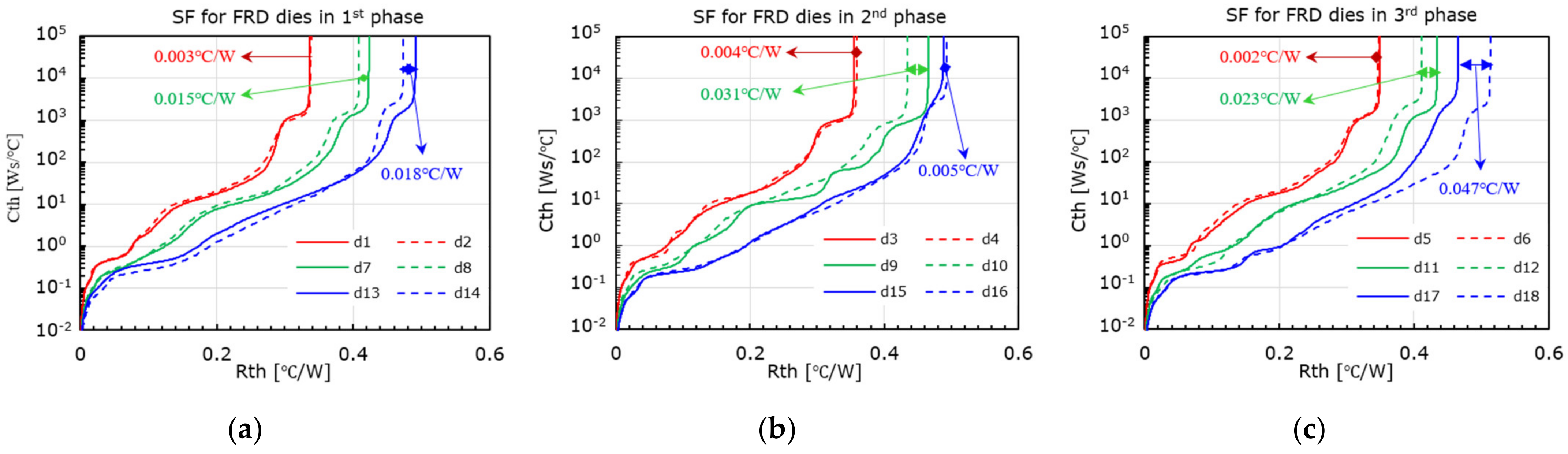
3.2. RC Characteristics of FRD Dies

Figure 5 shows the SFs of the heat-flow paths for the measured FRD dies. For GM_1 and boost, the SF curve of the upper side overlaps with that of the lower side in the first half of the RC map and appears different from that of the lower side in the second half of the RC map. This RC characteristic of FRD dies is similar to that of the corresponding IGBT dies. However, for GM_2 the SF curve of the upper side is same with that of the lower side in the whole RC map. This RC characteristic of FRD dies in GM_2 is different from that of IGBT dies in GM_2.
Since the SF curve of the upper side overlaps with that of the lower side in the RC map, the difference of Rth,JL between the upper side and the lower side in GM_2 is close to zero for FRD dies. The difference of Rth,JL in GM_2 changes little from the 1st phase to the 3rd phase.
For FRD dies in GM_1, the Rth,JL of the upper side is larger than that of the lower side of all three phases. The difference in Rth,JL between the upper side and lower side does not change much from the 1st phase to the 3rd phase.
However, the RC characteristics of the FRD dies in the boost unit are different from that of the FRD dies in GM_1 and GM_2. As shown in Figure 5, although the Rth,JL of the upper side is larger than that of lower side in the 1st phase, the Rth,JL of the upper side is a little less than that of the lower side in the 2nd phase, and is much less than that of the lower side in the 3rd phase.
Figure 6 shows the trend of changes in SF curves for FRD dies of boost unit from the 1st phase to the 3rd phase, where the SF curves of the three phases are added to one graph and aligned with the thermal resistance of heat-flow path. The SF curve of the upper side moves to the left whereas the SF curve of the lower side moves to the right in the RC map from the 1st phase to the 3rd phase. This makes the RC characteristics of FRD dies in the boost unit significantly different from the FRD dies in the GM_1 and GM_2 units, and even more different from the corresponding IGBT dies in the boost unit.
Table 1 shows the Rth,JL of FRD dies in the boost unit. It was found that from the 1st phase to the 3rd phase, the Rth,JL of the upper side reduced from 0.492 °C/W for d13 to 0.466 °C/W for d17, and the Rth,JL of the lower side increased from 0.474 °C/W for d14 to 0.513 °C/W for d18. Consequently, the difference in Rth,JL between the upper and lower sides for the FRD dies increased dramatically to a maximum value of 0.047 °C/W in the 3rd phase of the boost unit.
In summary, as shown in Figure 4 and Figure 5, the SF curve of the power dies on the upper side basically coincides with that of the lower side in the first half of the RC map and it is different from that of the lower side in the second half of the RC map. This means that the heat-flow paths probably appear significantly different between the upper side and the lower side in areas that correspond to the heat sink of the structure and its contact area with the coolant.
In addition, the RC characteristics of IGBT dies are different from those of FRD dies. For RC characteristics of IGBT dies, the Rth,JL of the upper side is less than that of the lower-side, and the trend of change in the difference of Rth,JL from the 1st phase to the 3rd phase in boost unit is different from that of other units. The difference of Rth,JL between the upper side and the lower side changes little from the 1st phase to the 3rd phase in GM_1 and GM_2. However, the difference of Rth,JL between the upper side and lower side changes a lot in the boost unit from the 1st phase to the 3rd phase, it increases from 0.008 °C/W to 0.038 °C/W.
For the RC characteristics of FRD dies, the trend of the change in Rth,JL is more complex. Firstly, the Rth,JL of the upper side is same as that of the lower side in GM_2. Secondly, the Rth,JL of the upper side is larger than that of lower side in the GM_1 unit. Thirdly, the Rth,JL of the upper side is larger than that of lower side in the 1st phase of the boost unit, whereas the Rth,JL of the upper side is less than that of the lower side in both the 2nd and 3rd phases.

4. Discussion

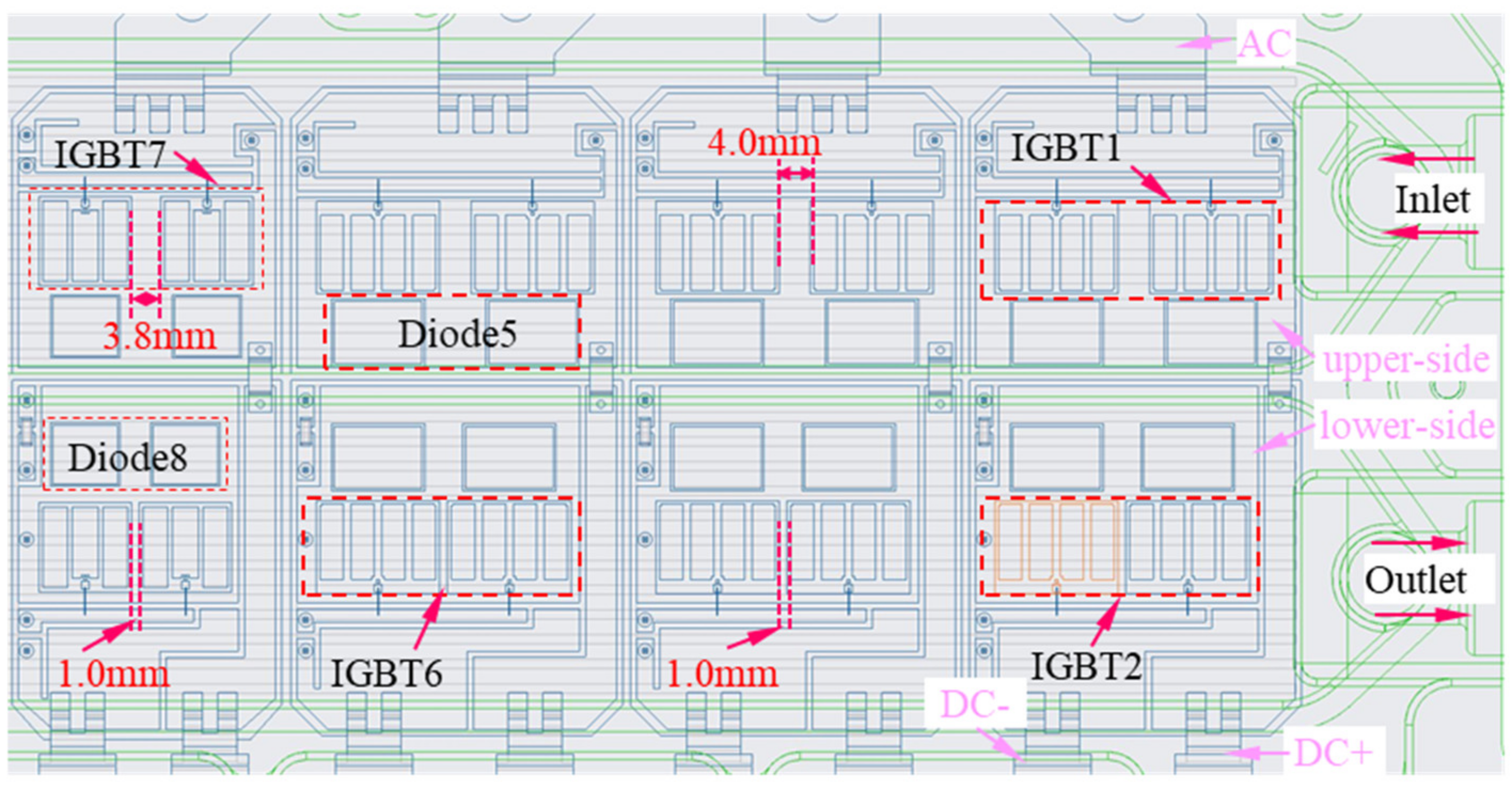
4.1. Placement Design of Power Dies on Heat Sink

These inconsistent RC characteristics of power dies shown in Figure 4, Figure 5 and Figure 6 are closely related to the high-density integration of the developed PCU module. Due to the constraints from the high-density integration of the PCU module, three power converter units are placed on the heatsink with a limited footprint and the parallel-connected power dies with high current ratings and the small-footprint of DBC have to be adopted. Figure 7a shows the whole placement design of power dies inside the developed PCU module. The types of power dies in the boost unit are same with those of GM_2, but the parallel number of power dies is different. Another type of power dies is used in the GM_1 unit; the parallel number of power dies is two.
As shown in Figure 7a, as a trade-off strategy for placing the components, which are related to power terminals on the side of “AC” power terminals, and reducing the parasitic parameters of electrical connections with DC-link capacitors on the side of “DC” power terminals, the direct bond coppers (DBCs) deviate as a whole from the center line for the fluid space of the liquid cooler, the FRD dies of the upper side are placed on the area which is closer to the isolation structure of the liquid cooler for the upper side and lower side (see the blue area). The area directly below the FRD dies of the upper side is closer to the isolation structure of the liquid cooler than that of the lower-side. Since the footprint size of the FRD dies in GM_2 and boost units are larger than that of the GM_1 unit, the part of the area directly below the FRD dies in GM_2 and boost even overlap with the isolation structure of the liquid cooler.
Figure 7b shows the heat-flow paths from the power dies to the coolant in a cross section of A–A. When the heat dissipates from the power dies to the coolant, it goes through the 1st solder layer between power dies and DBC, DBC, the 2nd solder layer between the DBC and heat sink, and heat sink in turn, and eventually transfers to the coolant. In order to enhance the heat dissipation efficiency of the contact area between the coolant and surface of the heat sink, a strip-pin structure is introduced to the bottom of the heat sink.
As shown in Figure 7b, the strip-fin structure of the heat sink dominates the whole heat-flow path from the power dies to the coolant. When coolant flows in fluid space, which is formed by both the heat sink and liquid cooler, the size of the contact area between the heat sink and coolant, which corresponds to the heat-flow paths of power dies, may be different from each other. This will cause a difference in the convection coefficient of the contact area for different power dies. The discrepancy in the convection coefficient of the contact area will results in different RC characteristics for power dies. Hence, the footprints of power dies and the lateral expansion of heat-flow paths for power dies in a strip-fin structure, as well as the speed of the coolant in the corresponding contact area, will influence the RC characteristics of power dies.
The cross-sectional area perpendicular to the heat-flow direction is different for the various units of the power converter (see Figure 7a) because of the different footprint sizes and parallel numbers of power dies. The material and structure of each layer are the same along with heat-flow paths (see red arrows in Figure 7b). Hence, the convection coefficients for the corresponding contact area of the heat-flow paths are significantly different among three power converter units. These have two consequences. The first is that the SFs are significantly different among the three power converter units, as shown in Figure 4 and Figure 5. The second is that the Rth,JL of the boost unit is much higher than that of the other units.
The FRD dies of the upper side are placed in the area that is closer to the isolation structure of the liquid cooler. The presence of the isolation structure reduces the convection coefficient of the contact area between the heat sink and the coolant to a certain extent. This is one of the reasons that the Rth,JL of the upper side is higher than that of the lower side for FRD dies.
Figure 8 shows the placement design of power dies in the boost unit. It is worth noting that the IGBT18 is placed in the area that is directly above the edge of the strip-pin structure. The lateral expansion of heat-flow paths in the strip-fin structure of the heat sink for IGBT18 is also weakened. The corresponding contact area between the strip-pin of the heat sink and the coolant for IGBT18 decreases. Consequently, the Rth,JL of IGBT18 is much larger than that of IGBT17 by 0.038 °C/W in the 3rd phase of the boost unit, as shown in Figure 4c.
The coupling of heat-flow paths for parallel power dies will also affect the size of contact area between the heat sink and coolant. For a single phase in GM_1 or GM_2, the cross-sectional area perpendicular to the heat-flow direction of the upper side are not significantly different from that of the lower side (see Figure 7b), but their SFs exhibit distinct characteristics between the upper side and lower side for both IGBT and FRD dies. These are attributed to the different lateral couplings of heat-flow paths for the parallel power dies due to the inconsistent placement design of parallel power dies on a heat sink.
Figure 9 shows the placement design of power dies in GM_1 and GM_2, where the green lines are the wireframe of the liquid cooler. The number of parallel power dies are two for every phase in GM_1 and GM_2, but the spacing of the parallel power dies is different from each other.
For FRD dies, although the spacings of parallel FRD dies on the lower side are less than those of the upper side, the spacings of the parallel FRD dies on the lower side are still large enough that the lateral coupling of heat-flow paths can be neglected. The difference in the heat-flow path coupling for parallel dies is small between the upper and lower sides. However, for IGBT dies, due to the limit of the small footprint of DBC and large size of IGBT dies, the spacing is relatively small. The lateral coupling of the heat-flow paths for parallel power dies cannot be neglected.
Table 2 summarizes the footprint size and spacing of the parallel IGBT dies. The spacing of the parallel IGBT dies on the upper side is larger than that of the lower side, the lateral coupling of heat-flow paths for the parallel IGBT dies of the lower side is stronger than that of the upper side. Consequently, the Rth,JL of the lower side is higher than that of the upper side for IGBT dies in GM_1 and GM_2, as shown in Figure 4.
The different spacings of parallel power dies between the upper and lower sides are the result of high-density integration designs of PCU modules. Since the location of the circuit interface for various components and the overall architecture of electrical control systems have been given, the design of power terminals is constrained in a PCU module. Firstly, the structure of power terminals is not uniform and the distance between them is different. Secondly, “DC+” and “DC−” power terminals are placed on one side of a PCU module and the power terminals for “AC” are placed on other side of the PCU module. In order to realize a half-bridge configuration on DBC with a limited footprint size, the partial area of DBC on the lower side has to be sacrificed for power transmission from “DC+” power terminals to DBC of the upper side. Consequently, the spacings of parallel IGBT dies on the lower side have to be reduced as much as possible. As shown in Figure 9 and Table 2, the spacing of parallel IGBT dies on the lower side is only 1 mm, whereas it is 4 mm for GM_2 and 3.8 mm for GM_1 in the upper side.
The placement of power dies inside a PCU module (as shown in Figure 7, Figure 8 and Figure 9) is constrained by the placement of DC-link capacitors and the overall architecture of PCU module, as well as the different footprint sizes of power converter units. The non-optimal placement design of power dies on a heat sink will cause a discrepancy in the RC characteristics of power dies. It is important to match the placement of power dies with the heat sink structure to shrink the inconsistent RC characteristics of power dies in highly integrated PCU modules.

4.2. Cooling Scheme of PCU Module

Compared with placement design of IGBT dies, the spacings of parallel FRD dies are large enough in GM_1 and GM_2. The lateral expansion of heat-flow paths does not result in significantly different couplings for the parallel FRD dies between the upper side and lower side. However, the RC characteristics of FRD dies are significantly different from those of IGBT dies.
On the other hand, FRD dies of the upper side are placed in an area that is closer to the isolation structure of the liquid cooler. The lateral expansion of heat-flow paths in the strip-pin structure area of the upper side is weakened because of the isolation structure of the liquid cooler. The Rth,JL of the upper side should be larger than that of the lower side for all units of a power converter. However, not all the experimental results obey this; only the experimental results of GM_1 confirm it. The Rth,JL for FRD dies of the upper side is almost same as that of the lower side in the GM_2 unit (see the red lines in Figure 5). The Rth,JL of the upper side in the boost unit is lower than that of the lower side by 0.005 °C/W for the 2nd phase and by 0.047 °C/W for the 3rd phase. These are probably related to the flow efficiency of coolant in the fluid space of the liquid cooler. In other words, in addition to the placement of power dies, the structural design of the liquid cooler and the liquid cooling scheme also affect the RC characteristics of power dies in highly integrated PCU modules.
For the developed PCU module, the coolant flows from the upper side of the GM_2 unit to the upper side of the GM_1 and boost units in turn, then it flows into the lower-side of the boost unit, enters the lower side of the GM_1 and GM_2 units in turn, and finally flows out of the outlet. The fluid speeds of the coolant in some local space of the liquid cooler may be different.
Figure 10 shows the simulation results of the flow speed of coolant in the liquid cooler. In the simulation, the conditions, such as power loss of dies, initial flow rate and temperature of coolant at the inlet of the liquid cooler, are consistent with those of previous experiments.
As shown in Figure 10a, the coolant flows faster in the fluid space that corresponds to FRD dies of the upper side in the boost unit; furthermore, the flow speed of coolant gradually increases in the fluid space along the flow direction of the coolant from the 1st phase to the 3rd phase. The increase in the flow speed of coolant will increase the convection coefficient of the corresponding contact area between the coolant and the surface of heat sink, and the thermal resistance will be reduced. The part of SF curve that is parallel to the vertical axis will appear in the area of lower thermal resistance in the RC map; that is, the 2nd half of the SF curve tends to move to the left in the RC map. This feature of SF curves is observed in experimental results of the boost unit, and is shown in Figure 6 (see solid lines).
As shown in Figure 10, the flow speed of coolant in the fluid space that is related to the FRD dies of the lower side in the boost unit changes little and maintains a relatively low value along the flow direction of coolant from the 3rd phase to the 1st phase. This means that the influence of different flow speeds on the SF curves of the lower side is negligible. However, since the d18 FRD die is placed in the area that is closer to the edge of the strip-fin structure (see Figure 8), the lateral expansion of the heat-flow path in the strip-pin structure of the heat sink is limited. The related convection coefficient is reduced. On the other hand, the speed of the coolant in the fluid space of the left of the strip-fin structure is much faster than that in the fluid space corresponding to the FRD die, d18. The convection coefficient of the contact area for d18 will probably also be influenced by the faster flow of coolant on the left side of the strip-fin structure. Therefore, the SF curve of d18 moves to the right (see the dashed line in purple in Figure 6) compared with FRD dies d16 and d14.
As shown in Figure 10b, the flow speed of coolant in the fluid space which corresponds to FRD dies of the upper side in the GM_2 unit is higher than that of the lower side. Hence, the Rth,JL of FRD dies in the upper side of the GM_2 unit that should have been higher is reduced, so the difference of Rth,JL for FRD dies between the upper and lower sides of GM_2 are negligible and are shown in Figure 5 (see red lines).
Above all, the inconsistent RC characteristics of power dies are related to the placement design of power dies and the structure of a liquid cooler, as well as the liquid cooling scheme of the developed PCU module. In order to facilitate the layout of various components and realize the optimal electrical connection with power terminals for a given overall architecture of an electrical control system, several trade-off strategies are adopted in the design of the developed PCU module.
Firstly, the “DC+” and “DC−” power terminals are placed on one side of PCU module and the “AC” power terminals are placed on the other side of the PCU module. In order to realize the half-bridge configuration of the DBC with a limited footprint size, the partial area of DBC on the lower side have to be sacrificed to transmit power from power terminal of “DC+” to the DBC of the upper side. Consequently, the spacings of parallel IGBT dies on the lower side are much smaller than those of the upper side. This results in the Rth,JL of the parallel IGBT dies on the lower side being higher those of the upper side.
Secondly, the layout of components that are related to “AC” power terminals and the optimal electrical connection between the DC-link capacitors and “DC” power terminals cause the DBCs (direct bond copper), as a whole, to deviate from the center line for the fluid space of the liquid cooler. Therefore, the FRD dies on the upper side are placed on the area that is closer to the isolation structure of the liquid cooler than that of the lower side. As a result, the Rth,JL of the FRD dies on the upper side is higher that of lower-side. The I18 IGBT dies have to be placed on the area that corresponds to edge of the strip-fin structure. This results in a much larger Rth,JL for I18 IGBT dies in the boost unit.
Thirdly, the inlet and outlet are placed on the same side of the PCU. Based on the present designs of the liquid cooler and liquid cooling scheme, the flow speed of coolant in the fluid space which is corresponding to FRD dies of upper-side is higher than that on the lower side. On the other hand, along the flow direction of coolant, the flow speed of coolant in the fluid space which corresponds to the FRD dies on the upper side in the boost unit gradually increases. Consequently, from the 1st phase to the 3rd phase, the difference in Rth,JL between the upper and lower sides for FRD dies of the boost unit appear more complicated than those of the GM_1 and GM_2 units.

5. Conclusions

In order to obtain a better thermal performance of PCU modules, the placement of power dies and the structure of liquid cooler, as well as a liquid cooling scheme, were optimized independently to improve the RC characteristics of power dies. However, it is challenging to implement individual optimizations in the thermal design of highly integrated PCU modules. As a result, the inconsistent RC characteristics of power dies are likely to exist in highly integrated PCU modules.
In this work, it was found that the inconsistent RC characteristics of power dies are the results of trade-offs in structural designs of highly integrated PCU modules. As the spacings of the parallel IGBT dies on the lower side are lower than those on the upper-side, the Rth,JL of the parallel IGBT dies on the lower side is higher than that of the upper side. Due to the limited lateral expansion of heat-flow paths in the strip-fin structure of the heat sink, the Rth,JL of FRD dies on the upper side is higher than that on the lower side, and the Rth,JL for I18 IGBT dies is higher than that of other IGBT dies in the boost unit. Due to the constraints from the designs of the liquid cooler and the liquid cooling scheme, the RC characteristics of the FRD dies in the boost unit are significantly different from the FRD dies of GM_1 and GM_2, and from the corresponding IGBT dies in the boost unit.
High-density integration brings a critical challenge for the thermal design of PCU modules. This work also revealed that it is important to match the placement of power dies with the heat-sink structure and the liquid cooler, as well as the liquid cooling scheme, in the design of highly integrated PCU modules. The matched design will alleviate the inconsistent RC characteristics of power dies and reduce the cost of liquid cooling for highly integrated PCU modules in EV/HEV applications. It is suggested that if the local strip-fin structure of a heat sink is optimized accordingly, these discrepancies in the Rth,JL of power dies could be reduced.

Author Contributions

Conceptualization, M.Z.; funding acquisition, S.Y. and K.S.; project administration, S.Y.; supervision, K.S.; writing—original draft, M.Z.; writing—review and editing, M.Z., Y.B. and S.Y.; All authors have read and agreed to the published version of the manuscript.

Funding

This work was supported by the National Key Research and Development Program of China under 2018YFB0104601.

Data Availability Statement

Data is contained within the article.

Conflicts of Interest

The authors declare no conflict of interest.

References

  1. Zhu, J.; Kim, H.; Chen, H.; Erickson, R.; Maksimović, D. High efficiency sic traction inverter for electric vehicle applications. In Proceedings of the 2018 IEEE Applied Power Electronics Conference and Exposition (APEC), San Antonio, TX, UAS, 4–8 March 2018; pp. 1428–1433. [Google Scholar]
  2. Eull, M.; Preindl, M.; Emadi, A. Analysis and design of a high efficiency, high power density three-phase silicon carbide inverter. In Proceedings of the 2016 IEEE Transportation Electrification Conference and Expo (ITEC), Busan, Korea, 1–4 June 2016; Institute of Electrical and Electronics Engineers (IEEE): Piscataway, NJ, USA, 2016; pp. 1–6. [Google Scholar]
  3. Matallana, A.; Ibarra, E.; López, I.; Andreu, J.; Garate, J.I.; Jorda, X.; Rebollo, J. Power module electronics in HEV/EV applications: New trends in wide-bandgap semiconductor technologies and design aspects. Renew. Sustain. Energy Rev. 2019, 113, 109264. [Google Scholar] [CrossRef]
  4. Sakr, N.; Sadarnac, D.; Gascher, A. A review of on-board integrated chargers for electric vehicles. In Proceedings of the 2014 16th European Conference on Power Electronics and Applications, Lappeenranta, Finland, 26–28 August 2014; IEEE: Piscataway, NJ, USA, 2014; pp. 1–10. [Google Scholar]
  5. Subotic, I.; Bodo, N.; Levi, E. An EV Drive-Train with Integrated Fast Charging Capability. IEEE Trans. Power Electron. 2016, 31, 1461–1471. [Google Scholar] [CrossRef] [Green Version]
  6. Ogawa, T.; Tanida, A.; Yamakawa, T.; Okamura, M. Verification of Fuel Efficiency Improvement by Application of Highly Effective Silicon Carbide Power Semiconductor to HV Inverter. SAE Tech. Pap. Ser. 2016. paper 2016-01-1230. [Google Scholar] [CrossRef]
  7. Hussein, K.; Ishihara, M.; Miyamoto, N.; Nakata, Y.; Nakano, T.; Donlon, J.; Motto, E. New compact, high performance 7th generation IGBT module with direct liquid cooling for EV/HEV inverters. In Proceedings of the 2015 IEEE Applied Power Electronics Conference and Exposition (APEC), Charlotte, NC, USA, 15–19 March 2015; pp. 1343–1346. [Google Scholar]
  8. Hohlfeld, O.; Herbrandt, A. Direct cooled modules-integrated heat sinks. In Proceedings of the 2012 7th International Conference on Integrated Power Electronics Systems (CIPS), Nuremberg, Germany, 6–8 March 2012; pp. 1–4. [Google Scholar]
  9. Li, B.; Kuo, H.; Wang, X.; Chen, Y.; Wang, Y.; Gerada, D.; Worall, S.; Stone, I.; Yan, Y. Thermal Management of Electrified Propulsion System for Low-Carbon Vehicles. Automot. Innov. 2020, 3, 299–316. [Google Scholar] [CrossRef]
  10. Nonneman, J.; T’Jollyn, I.; Clarie, N.; Weckx, S.; Sergeant, P.; De Paepe, M. Model-Based Comparison of Thermo-Hydraulic Performance of Various Cooling Methods for Power Electronics of Electric Vehicles. In Proceedings of the 17th IEEE Intersociety Conference on Thermal and Thermomechanical Phenomena in Electronic Systems (ITherm), San Diego, CA, USA, 29 May–1 June 2018; pp. 398–409. [Google Scholar]
  11. Liang, Z. Integrated double sided cooling packaging of planar SiC power modules. In Proceedings of the 2015 IEEE Energy Conversion Congress and Exposition (ECCE), Montreal, QC, Canada, 20–24 September 2015; Institute of Electrical and Electronics Engineers (IEEE): Piscataway, NJ, USA, 2015; pp. 4907–4912. [Google Scholar]
  12. Geinzer, T.; Schwarz, A.; Gleich, M. Innovations for IGBT based power modules in HEV drivetrain applications. In Proceedings of the PCIM Europe 2017, Nuremberg, Germany, 16–18 May 2017; pp. 1–3. [Google Scholar]
  13. Hayes, M.; Fruth, J.R.; Neelakantan, A. 650 V, 7 mOhm SiC-MOSFET development for dualside power modules in electric drive vehicles. In Proceedings of the PCIM Europe 2017, Nuremberg, Germany, 16–18 May 2017; pp. 1–6. [Google Scholar]
  14. Tang, G.; Wai, L.C.; Lim, S.B.; Lau, B.L.; Kazunori, Y.; Zhang, X.W. Thermal Analysis, Characterization and Material Selection for SiC Device Based Intelligent Power Module (IPM). In Proceedings of the 2020 IEEE 70th Electronic Components and Technology Conference (ECTC), Orlando, FL, USA, 3–30 June 2020; pp. 2078–2085. [Google Scholar]
  15. Kitazawa, O.; Kikuchi, T.; Nakashima, M.; Tomita, Y.; Kosugi, H.; Kaneko, T. Development of Power Control Unit for Compact-Class Vehicle. SAE Int. J. Altern. Powertrains 2016, 5, 278–285. [Google Scholar] [CrossRef]
  16. Zhang, M.; Yang, S.; Sheng, K. Thermal Resistance and Capacitance Characteristics of A 4-in-1 Integrated Power Control Unit (PCU) Module for Hybrid Electrical Vehicle (HEV). In Proceedings of the 2020 IEEE 9th International Power Electronics and Motion Control Conference (IPEMC2020-ECCE Asia), Nanjing, China, 31 May–3 June 2020; pp. 3092–3099. [Google Scholar]
  17. Hasan, M.I.; Tbena, H.L. Enhancing the cooling performance of micro pin fin heat sink by using the phase change materials with different configurations. In Proceedings of the 2018 International Conference on Advance of Sustainable Engineering and its Application (ICASEA), Pahang, Malaysia, 1 June 2018; pp. 205–209. [Google Scholar]
  18. Mademlis, G.; Orbay, R.; Liu, Y.; Sharma, N. Designing Thermally Uniform Heatsink with Rectangular Pins for High-Power Automotive SiC Inverters. In Proceedings of the IECON 2020 the 46th Annual Conference of the IEEE Industrial Electronics Society, Singapore, 18–21 October 2020; pp. 1317–1322. [Google Scholar]
  19. Liebig, S.; Nuber, M.; Kriegel, K.; Weidner, K. Ultra-compact SiC power module with sintered DCB on microchannel cooler. In Proceedings of the PCIM Europe 2015, Nuremberg, Germany, 19–21 May 2015; pp. 1–6. [Google Scholar]
  20. Hou, F.; Zhang, H.; Huang, D.; Fan, J.; Liu, F.; Lin, T.; Zhang, G. Microchannel Thermal Management System With Two-Phase Flow for Power Electronics Over 500 W/cm2 Heat Dissipation. Trans. Power Electron. 2020, 35, 10592–10600. [Google Scholar]
  21. Karayiannis, T.; Mahmoud, M. Flow boiling in microchannels: Fundamentals and applications. Appl. Therm. Eng. 2017, 115, 1372–1397. [Google Scholar] [CrossRef]
  22. Aranzabal, I.; De Alegria, I.M.; Delmonte, N.; Cova, P.; Kortabarria, I. Comparison of the Heat Transfer Capabilities of Conventional Single- and Two-Phase Cooling Systems for an Electric Vehicle IGBT Power Module. IEEE Trans. Power Electron. 2018, 34, 4185–4194. [Google Scholar] [CrossRef]
  23. Falsetti, C.; Magnini, M.; Thome, J. Hydrodynamic and thermal analysis of a micro-pin fin evaporator for on-chip two-phase cooling of high density power micro-electronics. Appl. Therm. Eng. 2018, 130, 1425–1439. [Google Scholar] [CrossRef]
  24. Liu, C.; Yu, H. Evaluation and Optimization of a Two-Phase Liquid-Immersion Cooling System for Data Centers. Energies 2021, 14, 1395. [Google Scholar] [CrossRef]
  25. Aranzabal, I.; De Alegria, I.M.; Garate, J.; Andreu, J.; Delmonte, N. Two-phase liquid cooling for electric vehicle IGBT power module thermal management. In Proceedings of the 2017 11th IEEE International Conference on Compatibility, Power Electronics and Power Engineering (CPE-POWERENG), Cadiz, Spain, 4–6 April 2017; pp. 495–500. [Google Scholar]
  26. Laloya, E.; Lucia, O.; Sarnago, H.; Burdio, J.M. Heat Management in Power Converters: From State of the Art to Future Ultrahigh Efficiency Systems. IEEE Trans. Power Electron. 2016, 31, 7896–7908. [Google Scholar] [CrossRef]
Figure 1. The photo of the developed power control unit (PCU) module.
Electronics 10 00958 g001
Figure 2. Circuit topology of the developed PCU module.
Electronics 10 00958 g002
Figure 3. Experiment platform for testing the resistance and capacitance (RC) characteristics of the PCU module: (a) testing equipment and (b) testing conditions.
Electronics 10 00958 g003
Figure 4. Structure functions (SFs) of heat-flow paths for the measured insulated gate bipolar transistor (IGBT) dies under heating current of 100 A: (a) 1st phase, (b) 2nd phase, (c) 3rd phase. The solid and dashed lines represent the SFs of heat-flow path for the power dies of the upper side and lower side, respectively, while the red, green and blue lines are the standards for SFs for GM_2, GM_1, and boost.
Electronics 10 00958 g004
Figure 5. SFs of heat-flow paths for the measured anti-parallel FRD dies under heating current of 100 A: (a) 1st phase, (b) 2nd phase, (c) 3rd phase. The solid and dashed lines represent the SFs of the upper side and lower side, respectively, while the red, green and blue lines are standard for GM_2, GM_1, and boost, respectively.
Electronics 10 00958 g005
Figure 6. Comparison of partial SF curve for FRD dies of the boost unit. The solid and dashed lines represent the SFs of the upper side and lower side, respectively, while the black, light purple and purple lines are the part of SF curves for the 1st, 2nd and 3rd phases, respectively.
Electronics 10 00958 g006
Figure 7. Structural design diagram of the developed PCU module: (a) placement design of power dies and (b) heat-flow paths for cross section of A–A.
Electronics 10 00958 g007
Figure 8. The placement design of power dies in the boost unit.
Electronics 10 00958 g008
Figure 9. The placement design of parallel power dies in GM_1 and GM_2, where the green lines are the wireframes of strip-fin structures of the heat sink at the bottom.
Electronics 10 00958 g009
Figure 10. Simulation results of flow speed of coolant in the fluid space of the liquid cooler: (a) the view without placement design of power dies and (b) the view with placement design of power dies.
Electronics 10 00958 g010
Table 1. Comparison of Rth,JL for FRD dies of the boost unit.
Phase No.1st Phase2nd Phase3rd Phase
Upper-side (℃/W)0.4920.4890.466
Lower-side (℃/W)0.4740.4940.513
Difference (℃/W)–0.0180.0050.047
Table 2. The footprint size and spacing of parallel IGBT dies.
Power Converter UnitBoostGM_1GM_2
Footprint size (mm)16.0 × 12.012.0 × 11.616.0 × 12.0
Spacing on upper side (mm)/3.84
Spacing on lower side (mm)/1.01.0
Publisher’s Note: MDPI stays neutral with regard to jurisdictional claims in published maps and institutional affiliations.

