1. Introduction
The reflectarray antenna was proposed in 1963 [
1]. The reflectarray antenna consists of reflected phase arrays and a feed waveguide, which efficiently reflect electromagnetic waves. For the operation frequency, several reflectarrays have been intensively realized in the microwave [
2,
3], terahertz [
4] and optical region [
5,
6].
Reflectarray antennas utilizing printed-patch arrays are becoming considerable alternatives to solid parabolic reflectors due to numerous advantages such as their low profile, low weight, and ease of transportation and fabrication [
7]. Since metals are nearly perfect conductors in the microwave region, metal patches with variable sizes are widely chosen to build up reflectarrays. Despite these advantages, the antennas suffer from the major drawbacks of printed reflectarray, which inherently suffer from a loss of substrate and the characteristics of narrow bandwidth behavior. There is an alternative antenna, a metal waveguide array antenna, due to the fact that the antenna does have any loss of dielectric materials [
8,
9]. The metal reflectarray antenna can be easily fabricated with low-cost machining technologies and constructed by the elaborate manipulation of phase shift for metallic grooves, which offer the possibility of high-gain, multi-beam, or beam-steering antenna. In this antenna, the phases of reflected waves are controlled by the manipulation of groove depths which results in the variation in surface impedance at the end of each groove.
Technological advancement involved in millimeter-wave bands has attracted a great deal of interest in many different research areas and industrial applications. Common millimeter-wave bands show promising frequency ranges for broadband communication, Gbps-class wireless network, and nondestructive imaging. Large millimeter-wave antennas are of growing interest for radar applications, adaptive cruise control, and collision avoidance in brownout or unclear view. These onboard systems require low-weight reflector antennas such as printed reflectors or reflectarrays. However, increasing the size of reflectarray antenna for the system requiring a larger reflector, the weight of reflectarray antenna rapidly increases. In this reason, metal-printed reflectarray antennas could be suggested and applied. The printed antenna is good for light-weight, but suitable for high-power systems, since metal thin film could be damaged or burned and dielectric substrate relatively is weaker and more lossy than common metal. One proposed method to avoid the loss of substrate and the unsuitability of high-power systems is a metal-only reflectarray with metallic rectangular grooves, in which sub-wavelength holes are open-ended.
In this letter, we suggest and report designed millimeter-wave metal reflectarray antennas with sub-wavelength holes for onboard and high-power systems and investigate the feasibility of designing lightweight reflectarray antennas using the relationship between the diameter of sub-wavelength holes and the frequency of interest. In an experiment looking at the radiation of the millimeter-wave from constructed reflectarrays, there is no significant change in radiation pattern between the reflectarray without sub-wavelength holes and the designed reflectarray. With an experiment regarding radiation patterns, we show the light high-gain reflectarray antenna and achieve a 25% reduction in weightcompared with metal reflectarray without sub-wavelength holes. The designed reflectarray antenna for wide-band operation shows 15% half-power bandwidth for the region of an operating frequency.
2. Design of Reflectarray Antennas
The reflection phase of a reflectarray element is generally designed to compensate the spatial phase delay from the feeder to that element. The reflection phase of the
n-th element,
is calculated as
where
is the propagation constant of the wave in free space.
is the distance from the feed horn to the
n-th element,
is the position vector of the
n-th element from the center of a reflectarray to the
n-th element, and
represents the main-beam direction. The radiated main-beam of a reflectarray will point at a specific direction to
-direction by manipulating the reflected phases of reflectarray elements. A constant phase,
means the absolute reflection phase required in the reflectarray design.
In the design concept of metal reflectarray antennas, the phase of each rectangular groove is appropriately controlled by the manipulation of groove depth. For broadside main-beam direction, the phase-matching condition for each groove is simply satisfied
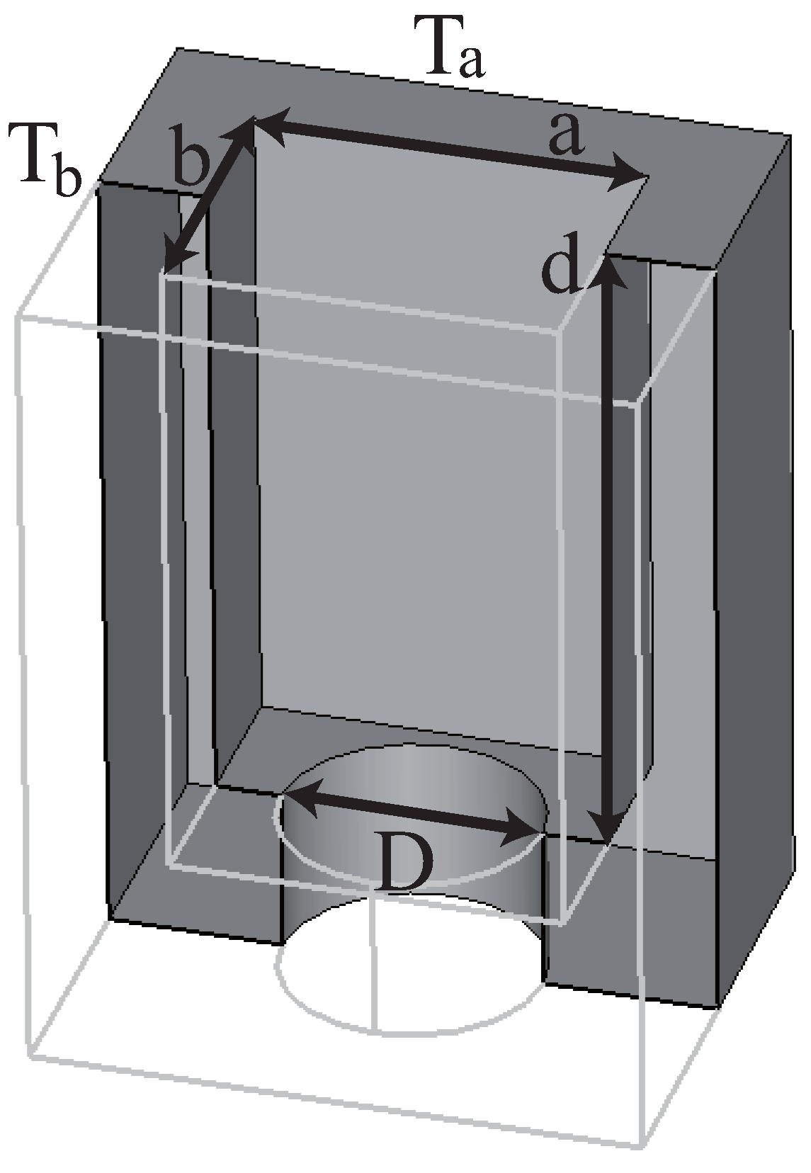
The unit groove is shown in
Figure 1 as metal reflectarray antenna building block. The working frequency is selected as 95 GHz (
∼3.16 mm). The grooves and sub-wavelength holes are designed in a ground metal plate, aluminum. The size of single element for the reflectarray is
a = 1.8 mm (0.57
),
b = 1.4 mm (0.44
),
= 2.3 mm (0.73
), and
= 1.9 mm (0.60
). Using Equation (
2), the depth of grooves,
d are tuned for broadside main-beam direction.
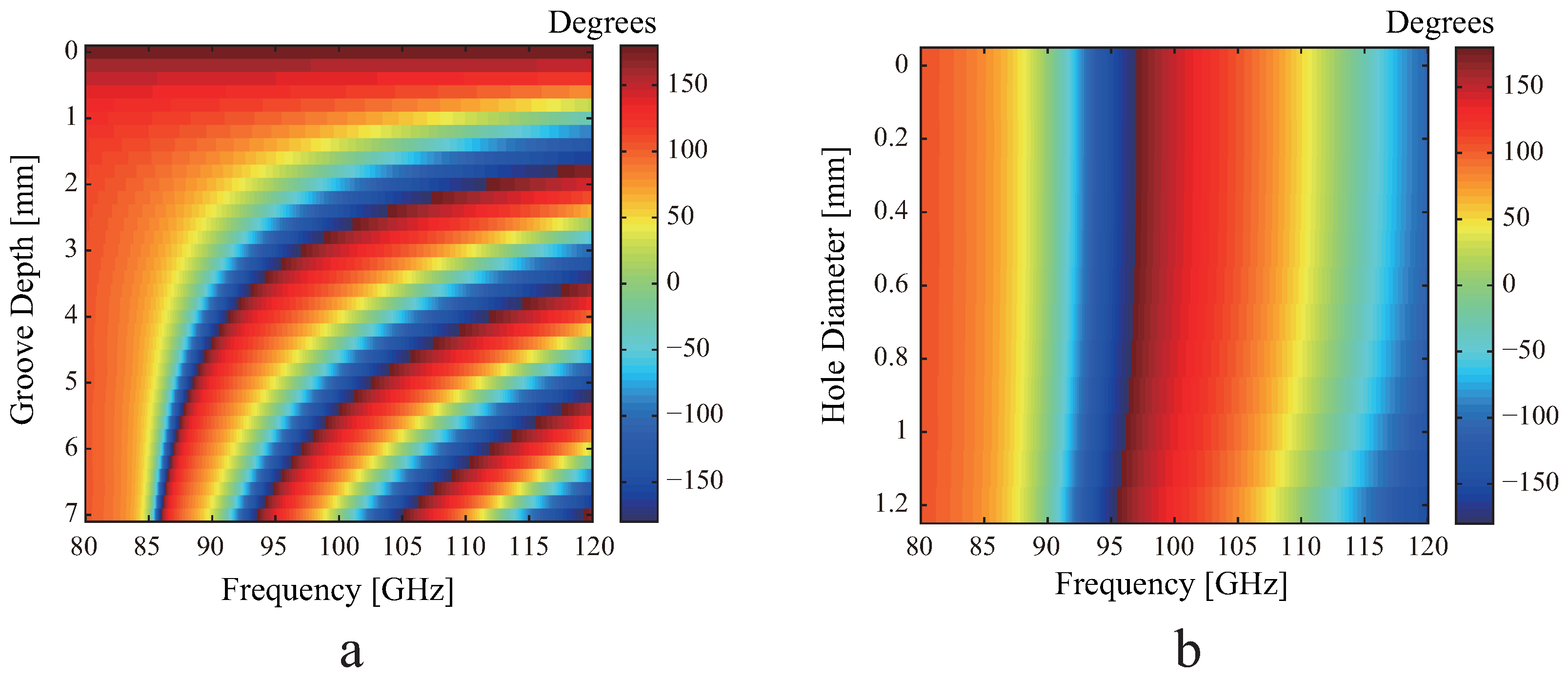
Figure 2a shows simulated reflection phase response of the unit groove in degrees, varying the depth of grove and frequency. The depth of groove is varied from 0 to 7 mm (1.07
) and the working frequency is also changed to check the sensitivity of reflected phases. The depth of groove,
d, is tuned under half the guided wavelength for the target frequency (0 ≤
d <
/2) because the required reflection phase can be fully satisfied from
to
due to the ground-plane reflection, the round trip propagation in each metal waveguide. The simulation is carried out using an electromagnetic full-wave tool, CST Microwave Studio under periodic boundary conditions with perfect electric and magnetic conductor and the incident wave is TM-polarized. The plasma frequency and damping frequency based of aluminum on the Drude model are 11.9 × 10
cm
and 6.60 × 10
cm
, respectively, in the millimeter wave region. Since the penetration depth of aluminum using this value is tan
∼300 nm, it is possible to approximate an aluminum plate as a perfect conductor [
10].
As depicted, a phase delay range of 360
is obtained by changing the groove-depth. For lower frequency regions, the slope of the non-linear phase shift is smoother and there is a relatively more insensitive phase-change than that of the metal printed-patch for different groove depths because the resonance of metal groove, the cutoff behavior, is less sensitive to frequency variations near resonance than that of metal printed-patches. We can anticipate that the metal groove reflectarray improves the bandwidth of the antenna because of the broadband characteristics of phasing elements shown in the phase diagram,
Figure 2a. These approaches will be simply implemented to make a rectangular waveguide in a ground metal plate, unlike other approaches, which are multilayer structures [
11], multi-resonant designs [
12], aperture coupled lines [
13] and true-time delay lines [
14].
3. Single Groove with a Sub-Wavelength Hole
As the above introduction mentioned, when increasing the size of the reflectarray antenna for high-gain antenna, the weight of metal-only antenna intuitively increases. For a high-gain and light millimeter-wave reflector, we suggest sub-wavelength holes in the rectangular grooves composing reflectarray antennas. Reasonably, the sub-wavelength holes in rectangular grooves do not change radiation properties and reflected electromagnetic waves from metal building elements to avoid the loss of substrate. In brief, the diameter of sub-wavelength hole is limited by the coupling between the millimeter-wave scattering filed and sub-wavelength hole. In order to avoid the coupling of millimeter-waves with sub-wavelength holes on the end of a rectangular groove, and also to secure high reflectivity of the scattered filed, the physical dimension of circular sub-wavelength holes is determined using a full-wave analysis.
Figure 2b shows simulated reflection phase diagram of the unit groove in degrees for
d = 3 mm (0.46
) when the diameter of sub-wavelength hole,
D, varies from 0 to 1.2 mm (0.18
, 0.38
). As shown in the figure, the sub-wavelength holes rarely affect the reflected phase from rectangular groove around the working frequency region and the loss of amplitude is nearly zero under −30 dB. A lower frequency than the working frequency does not need to be coupled to the rectangular grooves and propagate in the rectangular groove due to the cut-off behavior in a rectangular waveguide. The lowest cutoff frequency is 83.3 GHz for the single metal aperture. Thus, the designed reflectarray could not operate in a lower-frequency region. Increasing the diameter of the sub-wavelength hole, the diffraction loss of the guided wave in rectangular groove is critical, and the reflected phase curve shows the non-linear characteristics for the higher-frequency region. To obtain the most efffective light reflectarray antenna, we chose a sub-wavelength hole diameter of 1.2 mm. As shown in
Figure 2b, there is a relative robustness of reflected coefficients of rectangular grooves with sub-wavelength holes because the wavelength of the guided wave in rectangular groove is longer than that of the free-space.
4. Results and Discussions
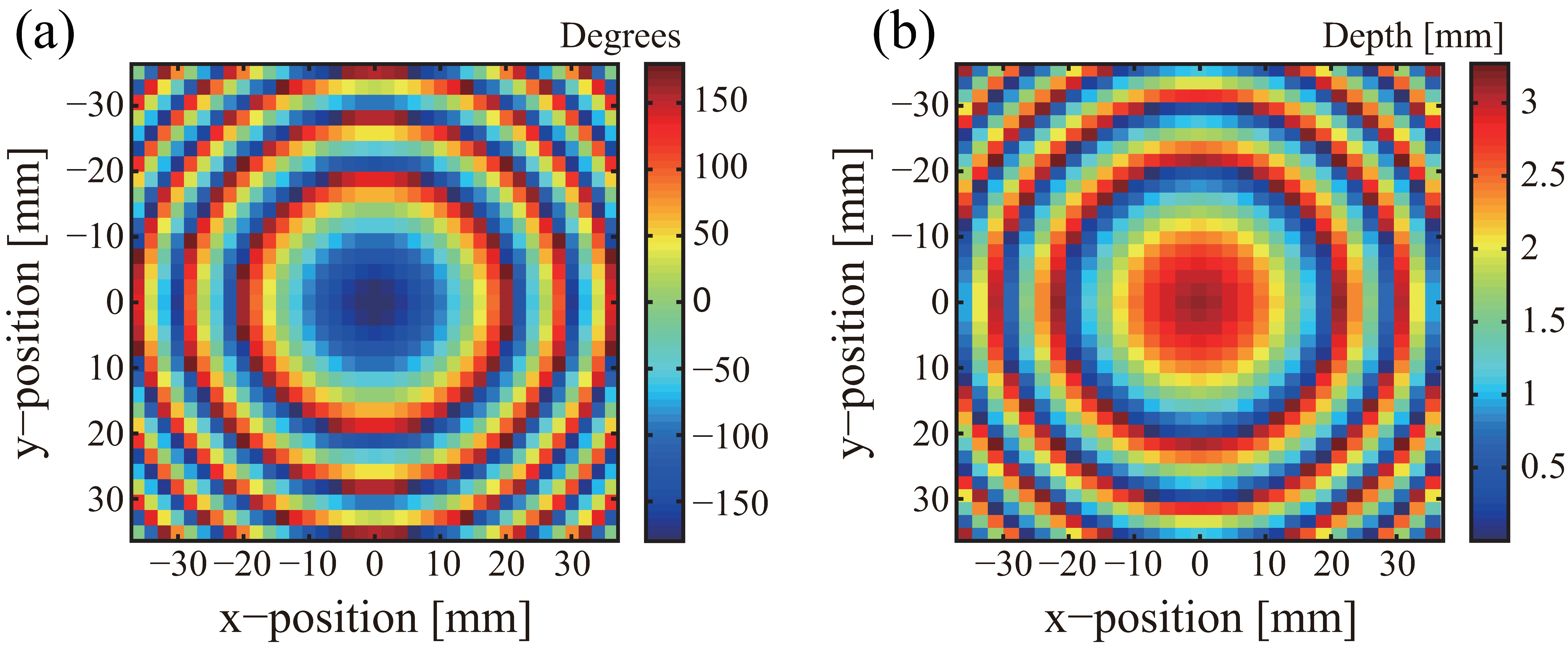
Figure 3 shows the required phases and depths for the millimeter-wave reflectarray antenna at each groove on the surface of the reflectarray. The required phases are calculated by Equation (
2) according to each groove location and feed location for the main-beam direction. There are 1147 (31 × 37) elements constructed on a 71.8 mm × 70.8 mm × 10 mm size aluminum metal plate (about 22
× 22
). The
f-number of designed reflector is 0.6. The distance from the focus the corner of the square is 78.37 mm. Consequently, a maximum 61.23 psec of time delay is necessary to compensate the 18.37 mm path difference of incident millimeter-wave from a pyramidal feeder. There are six zones, due to the phase compensation, as shown in
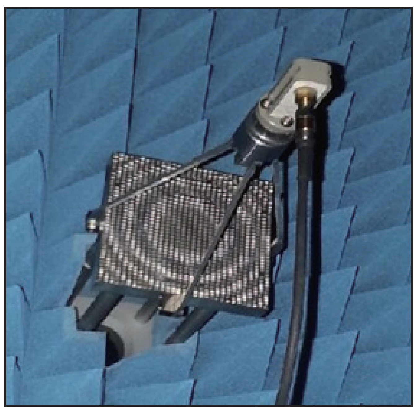
Figure 3. A photo of the constructed metal aperture array antenna with sub-wavelength holes (
D = 1.2 mm) is shown in
Figure 4.
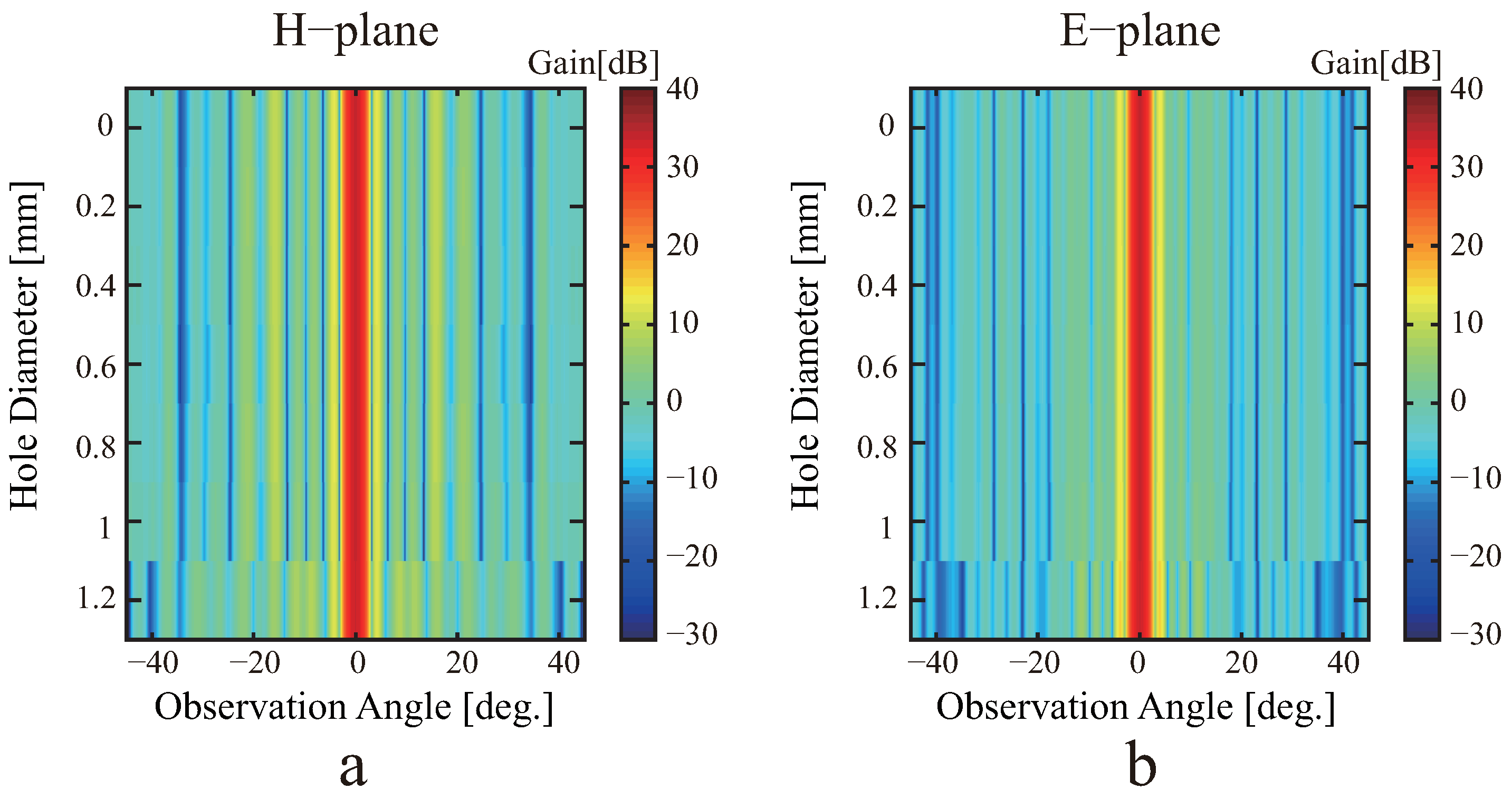
Figure 5a,b shows the simulated radiation patterns of reflectarray antennas when sub-wavelength hole diameters are changed in the range from 0 to 1.2 mm. As expected, the radiation patterns at working frequency are rarely changed changing the diameter of sub-wavelength holes from 0 to 1.2 mm in both planes.
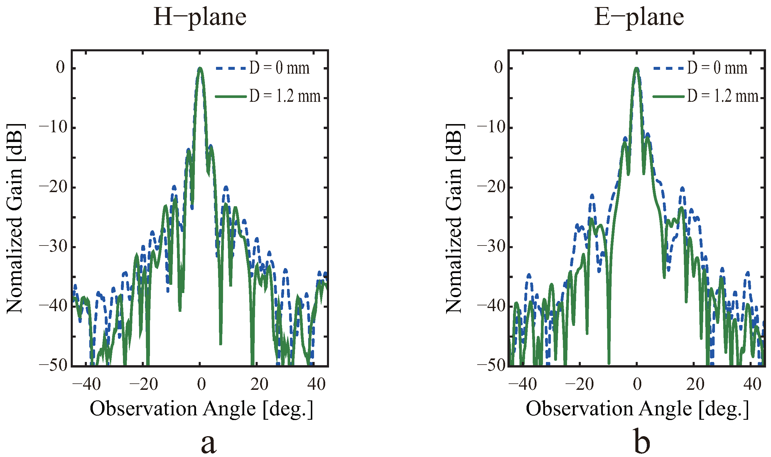
Measured radiation patterns of the antennas when the sub-wavelength hole diameters,
D, are 0 and 1.2 mm are shown as dashed and solid lines in
Figure 6a,b. The experiment is conducted in near-filed measurement system using a W-band rectangular pyramidal horn feeder with 14.7 dBi, which has a minimum reflection at working frequency. The experimental result has a good agreement with the simulated result for main-beam direction. The maximum gain of the reflectarray is 34.19 dBi and a half-power beam width is 2.34
for
D = 1.2 mm in H-plane.
Measured and simulated radiation performances of digitized metal reflectarray antennas in H-plane are summarized in
Table 1. Some differences between the two results are observed at the side lobe and measured gain. This is due to the interference from the circular fastening flange areas between the waveguides as feeder supports and the unwanted scattering fields at the edge of the conductor cells. It can be seen that the measured broadside gain is lower than simulated one under 0.3 dB. Such a gain reduction may mainly come from the blockage effects caused by waveguide flanges and struts. The inconsistency between the simulation results and experimental results may be the result of dielectric loss in real aluminum metal, as well as the effect of the screening. The gain value decreases in the case of real metal compared with the ideal perfect conductor due to dielectric loss. For the same reason, the side lobe level naturally decreases due to the loss and, because of the dielectric dispersion effect in real metal, the beam width is also widened.
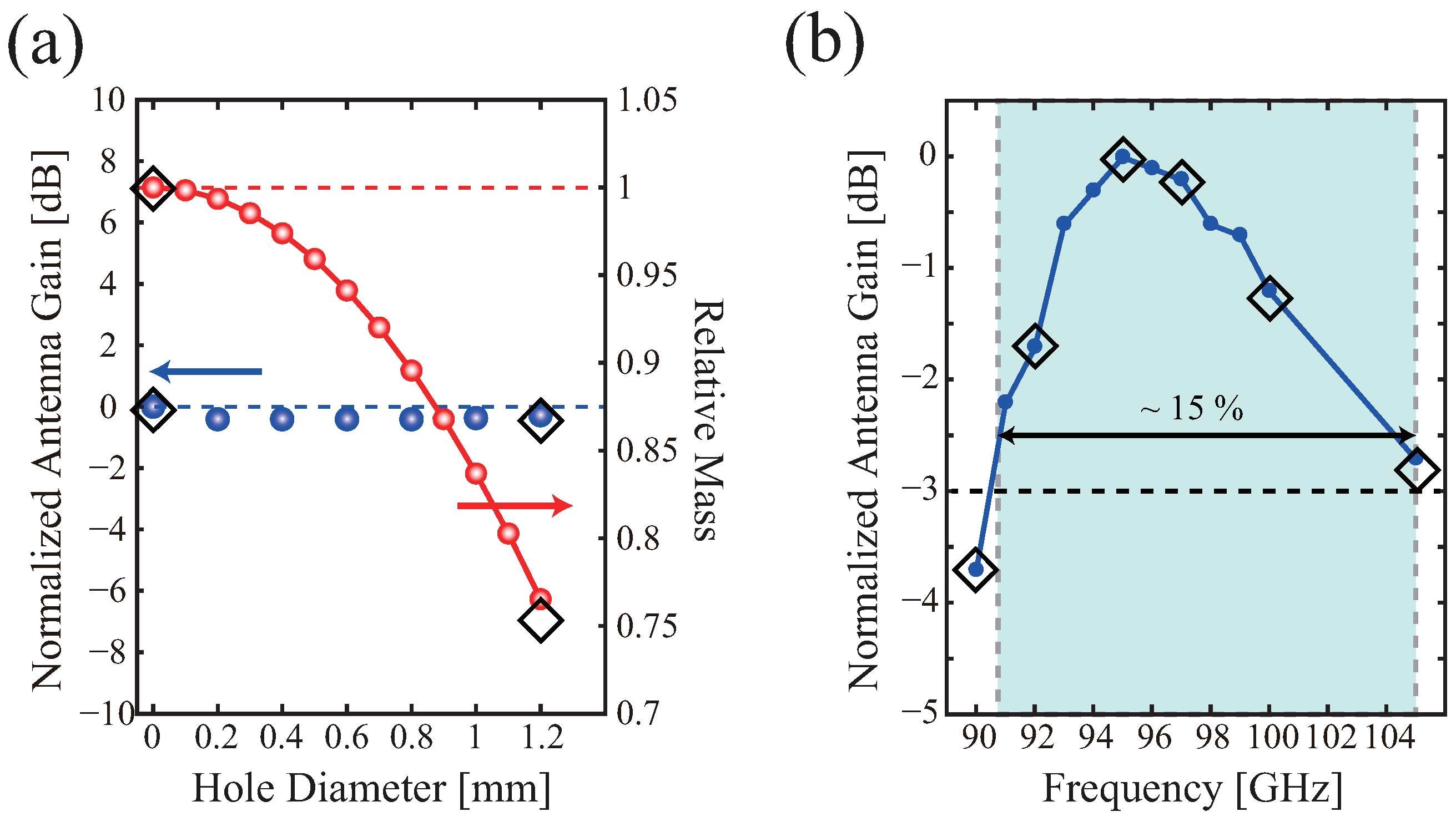
To verify the light reflectarray antenna, we measure and calculate the relative mass of reflectarray antenna.
Figure 7a shows a function of measured (diamond) and calculated gain and relative mass of reflectarray antennas for different sub-wavelength hole diameters. The total reduced mass is the volume sum of all sub-wavelength holes times the density of aluminum, 2.7 mg/mm
. The measured weights for two reflectarray antennas (
D = 0 and 1.2 mm) are 130.6 g and 98.4 g, respectively. The ratio of relative mass is about 0.75. We have designed the light high-gain reflectarray antenna. The mass of designed metal reflectarray antenna is reduced by 25% compared with the reflectarray without sub-wavelength holes.
For bandwidth wideness of reflectarray antenna for
D = 1.2 mm, the performances of antenna are numerically conducted over the frequency range from 90 to 105 GHz in W-band. The simulated antenna gains across the entire band are given in
Figure 7b. The measured gain below 95 GHz shows good agreement with the simulated one, but the discrepancy is increased at the higher frequency range due to the sensitve reflection phase variance. As shown in
Figure 2a, the error of realized required depth could be larger for higher-frequency parts. There is little difference between measured and simulated antenna gain due to the effect of a blockage and a diffraction caused by the waveguide flange and the supporting strut. Nevertheless, the half-power gain bandwidth of the antenna is 15%, and this antenna achieves its max gain of 34.23 dBi at working frequency. The metal groove reflectarray antenna can be simply obtained over a 15% wide-band operation without any consideration. Moreover, the air resistance can additionally be considered with the above-mentioned results. Moving the on-board system, the air resistance force proportionally increases with the square of reflector size. The resistance can be effectively reduced by implementing sub-wavelength holes in rectangular grooves that allow air to pass through the reflector and substantially decreases the air resistance pressure beyond the reflector.
5. Conclusions
In summary, we design millimeter wave metal reflective array antennas with sub-wavelength apertures for onboard and high-power systems. The sub-wavelength hole has little effect on the amplitude and phase reflected from the rectangular groove around the operating frequency region. Through propagation analysis and experimental results, there is no significant change in the radiation pattern between the reflectarray without sub-wavelength holes and the designed reflectarray.
Metal grooved reflectarray antennas can be obtained with a broadband operation of 15% or more around the operating frequency range due to the relative robustness of the reflection coefficient of the rectangular groove. Made of metal elements, these reflective arrays have very high radiation efficiencies compared to phased array antennas and PCB-based reflective array antennas. High-efficiency and high-power handling properties, without electrostatic breakdown by dielectrics, are useful in high-power microwave applications such as directional high-power microwave systems. The mass of the designed metal reflective array antenna is reduced by 25% compared to a reflective array without sub-wavelength apertures. Moreover, the sub-wavelength hole can allow air to flow, which reduces wind resistance from a large antenna as well as reducing the weight.
Finally, the very compact profile of the proposed metallized antenna and its wide operating bandwidth make it a good candidate for 5G millimeter wave communications applications providing fixed or scanning beams.
Author Contributions
Conceptualization, M.Y. and S.Y.; methodology, M.Y. and Y.B.; software, M.Y.; validation, M.Y. and Y.B.; formal analysis, M.Y. and S.Y.; investigation, M.Y.; resources, M.Y.; data curation, M.Y. and Y.B.; writing—original draft preparation, M.Y.; writing—review and editing, Y.B. and S.Y.; visualization, M.Y. and Y.B.; supervision, M.Y.; project administration, M.Y.; funding acquisition, M.Y. All authors have read and agreed to the published version of the manuscript.
Funding
This research received no external funding.
Conflicts of Interest
The authors declare no conflict of interest.
References
- Berry, D.G.; Malech, R.G.; Kennedy, W.A. The reflectarray antenna. IEEE Trans. Antennas Propag. 1963, 11, 645–651. [Google Scholar] [CrossRef]
- Chaharmir, M.R.; Shaker, J.; Cuhaci, M.; Ittipiboon, A. A broadband reflectarray antenna with double square rings. Microw. Opt. Technol. Lett. 2006, 48, 1317–1320. [Google Scholar] [CrossRef]
- Encinar, J.; Arrebola, M.; de la Fuente, L.F.; Toso, G. A transmit-receive reflectarray antenna for direct broadcast satellite applications. IEEE Trans. Antennas Propag. 2011, 59, 3255–3264. [Google Scholar] [CrossRef]
- Niu, T.; Withayachumnankul, W.; Ung, B.S.-Y.; Menekse, H.; Bhaskaran, M.; Sriram, S.; Fumeaux, C. Experimental demonstration of reflectarray antennas at terahertz frequencies. Opt. Express 2013, 21, 2875–2889. [Google Scholar] [CrossRef] [PubMed]
- Ginn, J.; Lail, B.; Alda, J.; Boreman, G. Planar infrared binary phase reflectarray. Opt. Lett. 2008, 33, 779–781. [Google Scholar] [CrossRef] [PubMed]
- Ahmadi, A.; Ghadarghadr, S.; Mosallaei, H. An optical reflectarray nanoantenna: The concept and design. Opt. Express 2010, 18, 123–133. [Google Scholar] [CrossRef] [PubMed]
- Huang, J.; Encinar, J.A. Reflectarray Antennas; John Wiley & Sons, Inc.: Hoboken, NJ, USA, 2008. [Google Scholar]
- Cho, Y.H.; Byun, W.J.; Song, M.S. Metallic-rectangulargroovesbased 2D reflectarray antenna excited by an open-ended parallel-plate waveguide. IEEE Trans. Antennas Propag. 2010, 58, 1788–1792. [Google Scholar]
- Yi, M.; Lee, W.; So, J. Design of cylindrically conformed metal reflectarray antennas for millimetre-wave applications. Electron. Lett. 2014, 50, 1409–1410. [Google Scholar] [CrossRef]
- Ordal, M.A.; Bell, R.J.; Alexander, R.W.; Long, L.L.; Querry, M.R. Optical properties of fourteen metals in the infrared and far infrared: Al, Co, Cu, Au, Fe, Pb, Mo, Ni, Pd, Pt, Ag, Ti, V, and W. Appl. Opt. 1985, 24, 4493–4499. [Google Scholar] [CrossRef] [PubMed]
- Encinar, J.A. Design of two-layer printed reflectarrays using patches of variable size. IEEE Trans. Antennas Propag. 2001, 49, 1403–1410. [Google Scholar] [CrossRef]
- Li, H.; Wang, B.Z.; Shao, W. Novel broadband reflectarray antenna with compound-cross-loop elements for millimeter-wave application. J. Electromagn. Waves Appl. 2007, 21, 1333–1340. [Google Scholar] [CrossRef]
- Venneri, F.; Costanzo, S.; Di Massa, G.; Amendola, G. Aperture-coupled reflectarrays with enhanced bandwidth features. J. Electromagn. Waves Appl. 2008, 22, 1527–1537. [Google Scholar] [CrossRef]
- Carrasco, E.; Encinar, J.A.; Barba, M. Bandwidth improvement in large reflectarrays by using true-time delay. IEEE Trans. Antennas Propag. 2008, 56, 2496–2503. [Google Scholar] [CrossRef]
| Publisher’s Note: MDPI stays neutral with regard to jurisdictional claims in published maps and institutional affiliations. |
© 2021 by the authors. Licensee MDPI, Basel, Switzerland. This article is an open access article distributed under the terms and conditions of the Creative Commons Attribution (CC BY) license (https://creativecommons.org/licenses/by/4.0/).


