Article

Suppressing Buffer-Induced Current Collapse in GaN HEMTs with a Source-Connected p-GaN (SCPG): A Simulation Study

1
State Key Laboratory of Artificial Microstructure and Mesoscopic Physics, School of Physics, Peking University, Beijing 100871, China
2
Institute of Microelectronics, Peking University, Beijing 100871, China
*
Author to whom correspondence should be addressed.
Electronics 2021, 10(8), 942; https://doi.org/10.3390/electronics10080942
Submission received: 7 March 2021 / Revised: 8 April 2021 / Accepted: 13 April 2021 / Published: 15 April 2021
(This article belongs to the Section Semiconductor Devices)

Abstract

:
Carbon doping in the buffer of AlGaN/GaN high-electron-mobility transistors (HEMTs) leads to the notorious current collapse phenomenon. In this paper, an HEMT structure with a source-connected p-GaN (SCPG) embedded in the carbon-doped semi-insulating buffer is proposed to suppress the buffer-induced current collapse effect. Two-dimensional transient simulation was carried out to show the successful suppression of buffer-induced current collapse in the SCPG-HEMTs compared with conventional HEMTs. The mechanism of suppressing dynamic on-resistance degradation by ejecting holes from the SCPG into the high resistive buffer layer after off-state stress is illustrated based on energy band diagrams. This paper contributes an innovative device structure to potentially solve the buffer-induced degradation of the dynamic on-resistance in GaN power devices.

1. Introduction

Gallium nitride (GaN) high-electron-mobility transistors (HEMTs) on silicon substrate are excellent candidates for next-generation high-voltage power electronics [1,2,3,4]. Polarization effects in AlGaN/GaN heterostructures introduce high-density and high-mobility two-dimensional electron gas (2DEG) [5,6,7], which lowers on-state resistance (Ron) and energy waste in power switches. Usually, a semi-insulating GaN buffer layer is required before the growth of the AlGaN/GaN heterostructure to avoid unwanted parallel current paths and ensure excellent pinch-off characteristics. The buffer layers are commonly realized by carbon-doped GaN, obtained by controlling the growth pressure, V/III ratio, and growth temperature [8], or adding an external carbon source [9] during MOCVD growth. The carbon-doped buffer layer can enhance the breakdown voltage (BV) of devices for carbon and serves as a deep acceptor impurity to compensate the residual carriers introduced by unintentional background n-type dopants, such as VN and O [8]. However, introducing carbon into the buffer also exacerbates the notorious current collapse (CC) or named dynamic on-resistance degradation phenomenon in GaN HEMTs [10,11].
The degradation of dynamic on-resistance of HEMTs exhibits a time-dependent and reversible deterioration of on-state conduction after high-voltage off-state stress [12,13]. The degradation results from charge storage by traps either on the surface or in the bulk. Surface trapping effects can be mitigated by the use of field plates [14] to weaken the electric field at the gate edge of the drain side, and passivation technique [15] to reduce the density of surface states. Tang et al. utilized a photonic-ohmic drain structure to generate photons, pumping electrons from deep surface traps [16]. Tanaka et al. placed an additional p-GaN near the drain on the surface to address the dynamic on-resistance degradation [17]. Surface cleaning techniques, such as plasma treatment [18] and ozone oxidation combined with wet etching [19], are also helpful to reduce CC caused by surface trapping.
The above-mentioned techniques have all been employed to resolve the surface-oriented trapping. A few techniques were proposed to address the trapping issue in carbon-doped buffers. An AlGaN back-barrier is commonly employed to block hot carriers from the channel into the buffer [20], but it also decrease 2DEG density because the back-barrier induces a sheet of negative charges at the GaN/AlGaN interface below the 2DEG channel. UV light was found to be able to suppress charge trapping in the buffer of GaN HMET [21], and changes in the trapping effect of devices exposed to UV light also influenced device output and noise characteristics [22,23,24]. Kang et al. used a buffer layer consisting of multiple carbon-doped and undoped GaN layers to compensate the deep-acceptor states in the carbon-doped parts by electrons transferred from the undoped GaN regions [25,26], which helps to weaken buffer-induced CC under low drain voltage stress.
In this study, an HEMT structure is proposed to further mitigate buffer-induced current collapse. With a source-connected p-GaN (SCPG) embedded in the highly resistive buffer, SCPG-HEMTs exhibit almost immunity to buffer-induced CC compared with conventional HEMTs (C-HEMTs). Its effect to suppress CC was demonstrated in this study by transient simulations, and the correlated mechanism is illustrated in the form of an energy band diagram.

2. Simulation Model

Figure 1 shows simulated device structures of the conventional HEMT and the proposed SCPG-HEMT. The conventional device consists of a Si substrate, an insulating strain release layer (SRL), a 2 μm carbon-doped semi-insulating GaN buffer layer, a 300 nm unintentional doped (UID) GaN and a 20 nm Al0.22Ga0.78N barrier layer capped with a 200 nm thick Si3N4 passivation layer. The gate is 1 μm in width, the gate–drain distance is 5 μm, and the gate–source distance is 1 μm. The structure difference of SCPG-HEMT is a 1 μm thick p-GaN in the middle of the buffer layer on the source side. A p-type ohmic contact electrically shorted with the source metal is on the surface of the p-GaN. The proposed structure can be achieved through an ICP etching and regrowth technique by MOCVD in real device fabrication.
In this work, simulation was carried out by Sentaurus TCAD. Parameters used in the simulation are summarized in Table 1, although some material default values are not listed. The 2DEG was simulated with fixed positive charges of 1.1 × 1013 cm−2 at the Al0.22GaN0.78N/GaN interface equivalent to the polarization-induced charge density [27]. The mobility of 2DEG in the heterostructure channel was set to be 2000 cm2/v·s, and that of electrons in the other regions was set to be 800 cm2/v·s. The mobility of hole was set as 10 cm2/v·s. The Source and Drain ohmic contact resistances were set as 0.5 Ω·mm. The ohmic contact of the source-connected p-GaN was set as 50 Ω·mm. Schottky barrier height was set to be 1.02 eV [28]. The donor density Nd in the UID GaN layer was 1 × 1015 cm−3. The carbon-doped buffer layers were set to be slightly p-type in simulation, because experiments have revealed that the carbon-doped buffer showed positive Hall coefficients [29] even though carrier concentration was extremely low. Therefore, in the simulation, the effective hole concentration was set to be 1 × 105 cm−3 [30] to form a semi-insulating buffer. The hole density in the SCPG was 5 × 1017 cm−3 in the simulation. Several experiments have identified that the energy level Ev + 0.86 eV is associated with buffer-induced current collapse [31,32]. The deep acceptor level is most likely to represent CN. The density of acceptor traps was set to be 5 × 1017 cm−3, considering the high self-compensation ratio of CN/CGa in GaN doped with high-concentration carbon around 1019 cm−3 [33]. The electron and hole capture cross sections for the deep traps were both set to be a typical value of 1 × 10⁻¹⁵ cm2 [32].
In the simulation, the following models were carried out. The state distribution of electrons and holes obeyed Fermi–Dirac statistics model. The constitutive charge transport of both electron and hole was based on a drift-diffusion model. The dynamic capture and emission behavior of traps was calculated based on the Shockley–Read–Hall recombination model [34]. Poisson’s equation was carried out to calculation electric field and charge distribution, including space charges and charges of ionized acceptor traps. An acceptor trap is neutral when empty, and negatively charged when ionized, and its electrical state is (0/−1) representing whether it is being occupied by electrons. In the simulation, the acceptor traps were able to capture and emit carriers from the conduction band and valance band. The ionized trap density, which would cause 2DEG depletion during the on-state, depends on the trap density, N t A , and probability of electron occupation of the acceptor traps, F t A :
N t A = F t A × N t A
F t A can be calculated based on the detailed balancing principle [35]:
F t A = v n σ n n + e p A v n σ n n + v p σ p p + e n A + e p A
where v n and v p represent the thermal velocity for electrons and holes, respectively, n and p are the concentrations of electron and hole carriers, σ n and σ p are defined as the capture cross sections for electrons and holes, and e n A and e p A are emission rates of electrons and holes. e n A and e p A can be calculated by the following equations:
e n A = D v n σ n n i e E t E i k B T
e p A = D v p σ p n i e E i E t k B T
where E i is the intrinsic Fermi level position, E t is the trap energy level, and D is the degeneracy factor of the trap center.

3. Simulation Results

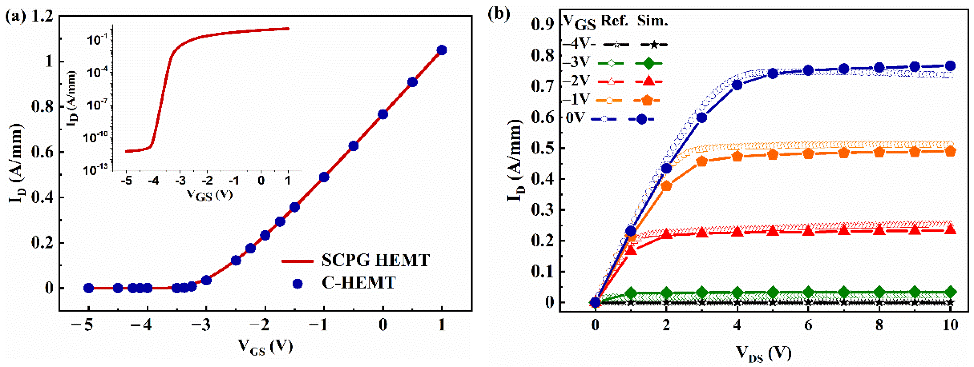
Figure 2a shows the transfer curves of SCPG-HEMT with the inset in logarithm scale. The transfer curve of the C-HEMT is also shown for comparison. SCPG-HEMT has an almost identical drain output capacity as the C-HEMT without any shift of threshold voltage resulting from the p-GaN. Therefore, introducing the p-GaN region would neither elevate the energy band nor deplete the 2DEG in the channel. Additionally, the output characteristics were compared between the simulated device and real depletion-mode HEMT device on the Si substrate, with the same 20 nm Al0.22Ga0.78N/300 nm GaN heterojunction. As shown by Figure 2b, the simulated current curves (solid points) fit well with real measurement (hollow points), which indicates the credibility of the simulation models and parameters.
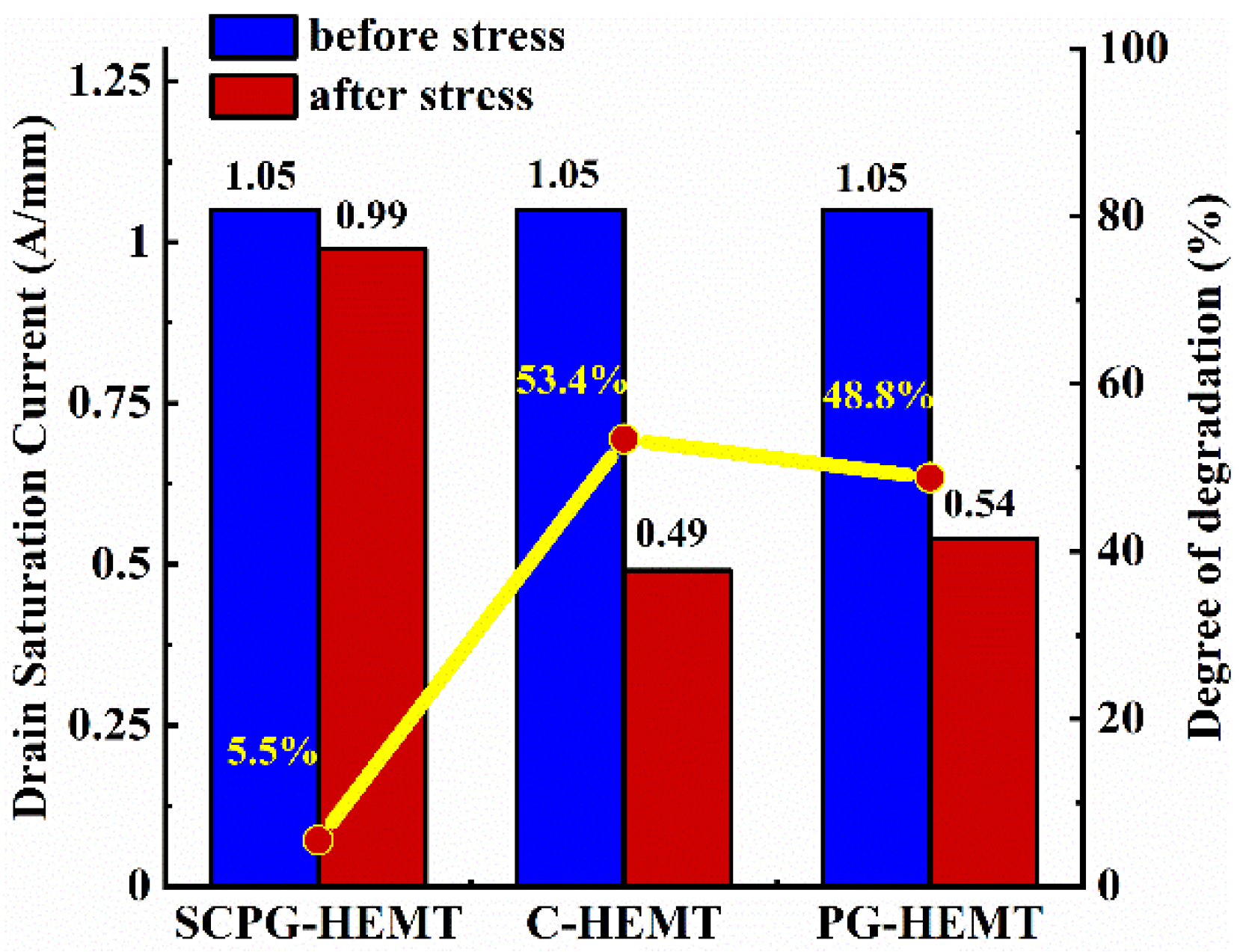
For current collapse evaluation, the simulation was performed with a pulsed I-V measurement. The device was initially biased in an off-state with a drain voltage of 600 V and a gate voltage of −5 V. Then, the device voltage was pulsed to the on-state biases and the drain current was recorded 1 μs after the transition. The behavior of current collapse effect in the SCPG-HEMT and the reference device is shown in Figure 3a,b. The C-HEMT suffered from severe current collapse, as the saturation drain current degraded from 1.05 A/mm to 0.49 A/mm for VGS = 1 V and declined to almost zero for VGS = −1 V, as shown in Figure 3a. By contrast, the proposed SCPG-HEMT showed a remarkable mitigation of buffer-induced current collapse after 1 μs recovery, as shown in Figure 3b. The saturation drain current of SCPG-HEMT only degraded from 1.05 A/mm to 0.99 A/mm for VGS = 1 V. The difference of degradation in saturation current for VGS = 1 V before and after stress between C-HEMT and SCPG-HEMT is summarized in Figure 4. The degree of degradation, determined by 1 I p o s t s t r e s s / I p r e s t r e s s , is also included in Figure 4. The degree of degradation of C-HEMT was 53.4%, which is in a similar level with the reported experimental values of carbon-doped buffer HEMT under 650 V stress [36]. By contrast, the proposed SCPG-HEMT only had an insignificant 5.5% degradation. Figure 4 also reveals the degree of buffer-induced CC when the p-GaN is not shorted to the source electrode and is electrically floating, which is named as PG-HEMT in this article. Electrically floating the p-GaN resulted in no distinct improvement in CC compared to C-HEMT. The mechanisms of SCPG-HEMT in terms of mitigating buffer-induced CC and the indispensability of shorting p-GaN layer to the source electrode are explained in the following section.

4. Discussion

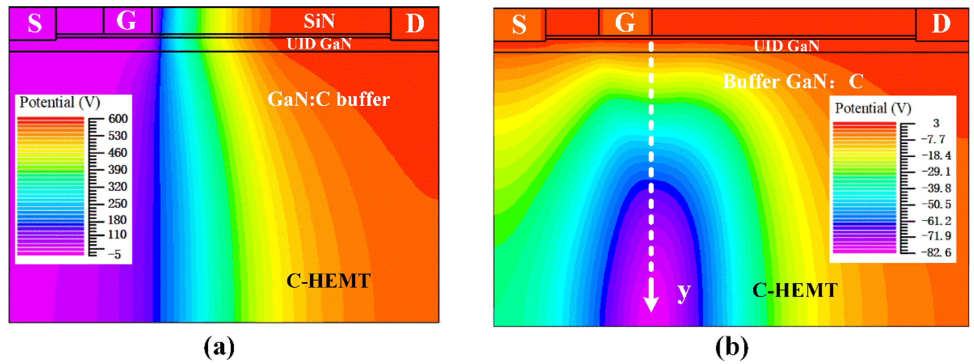
To investigate the causation of CC in C-HEMT after high voltage off-state stress, the energy band and charge distribution were analyzed based on the simulation. Figure 5a–c shows the schematic band diagram of C-HEMT, before stress, during stress, and in a recovery process, in the vertical direction, at a location close to the gate edge on the drain side, as labeled by the y-axis in Figure 6b. Initially, the acceptor traps are partially occupied by electrons because the Fermi level is located close to the acceptor trap energy level [37] in the GaN:C buffer, as shown in Figure 5a. When high voltage was applied on the drain electrode during the off-state, the electric field crowded under the gate edge of the drain side, as indicated by the potential distribution of C-HEMT during the off-state in Figure 6a. Under the gate edge, the UID GaN and the buffer behaved similarly to a reverse-biased p–n+ junction [30]. The space charge region in the buffer swiftly expanded to the whole buffer. The holes in the buffer were depleted [30] and the quasi-Fermi level in buffer was raised, ionizing acceptor traps by emitting holes from traps to valence bands; then, those holes were swept out of the space charge region by the electric field, as shown in Figure 5b. When the off-state stress was removed, the captured electrons were unable to emit to the conduction band because of the large energy band gap of GaN. The only way to emit the trapped electrons was to capture holes from valance band, and the capture rate was proportional to the hole density in the valence band. However, the off-state voltage swept away almost all the holes, which were scarce in the first place. Moreover, the generation of holes by thermal emission in a wide band semiconductor was too long. In addition, the high resistance of semi-insulating buffer meant that it took a long time for removed holes to return to the buffer, because the dielectric relaxation time of the buffer is huge. The dielectric relaxation time represents the time scale to return to electrical equilibrium. Therefore, the originally scarce holes would not return to the buffer even a long time after the off-state stress is removed. Without sufficient holes, the acceptor traps remain ionized and are unable to discharge, which results in a high residual buffer potential, and C-HEMT remains in a non-equilibrium state, as illustrated in Figure 5c. It can be seen from Figure 6b that the residual buffer potential was as high as −82 V at 1 μs after stress in the simulation. The buffer served as a virtual back gate, applying −82 V bias respect to the channel, which depleted the 2DEG above and induced serious current collapse.
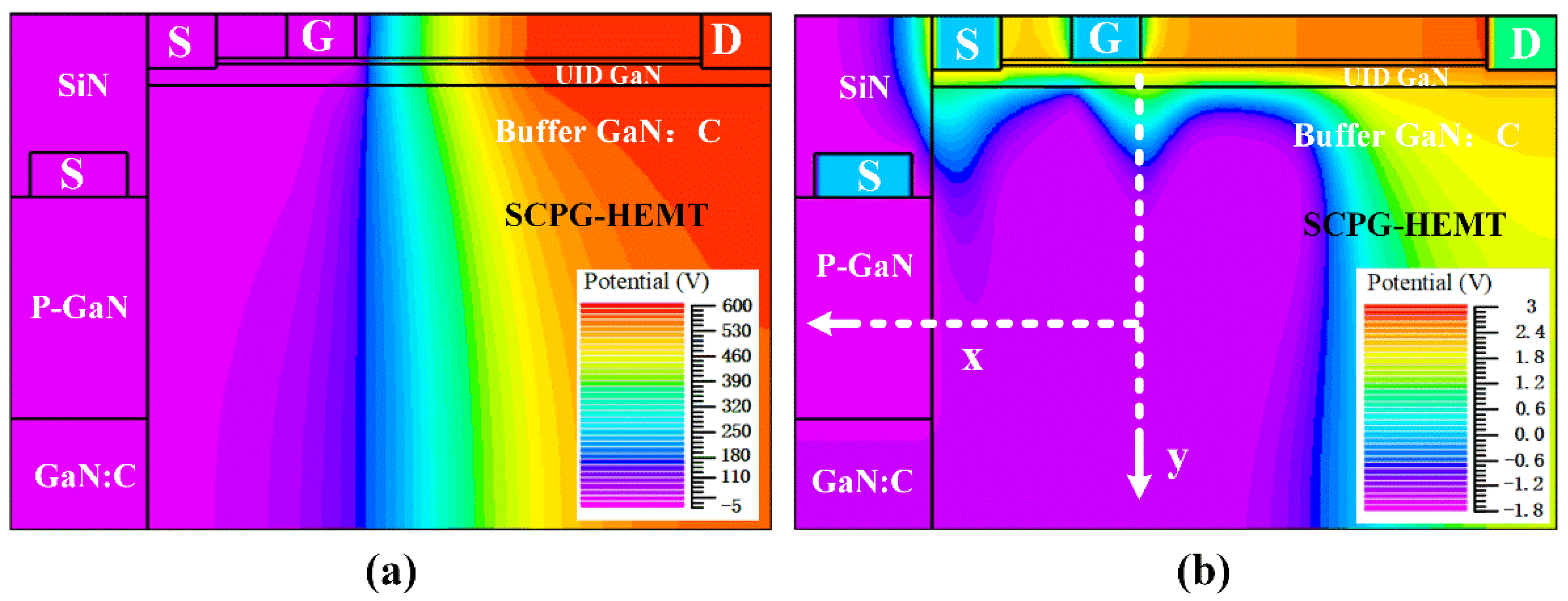
On the other hand, for the SCPG-HEMT, buffer-induced CC was successfully suppressed. Before the off-state stress was applied, the added p-GaN would not change the initial equilibrium in the GaN:C buffer and the status of traps in SCPG-HEMT were identical, as in C-HEMT where the electrons partially occupy the traps. As a result, the energy band diagram before stress is the same as C-HEMT in Figure 5a. Figure 7a shows the potential distribution of SCPG-HEMT during the off-state; the high electrical potential from drain electrode is shielded by the gate. Therefore, the added p-GaN region would not impair the device breakdown voltage and also would not exert influence on the buffer during stress. Consequently, the energy diagram of the SCPG-HEMT under the gate edge is the same as for C-HEMT, where holes are swept out of the buffer and acceptor traps are ionized, as depicted in Figure 5b. Therefore, the energy diagram of SCPG-HEMT before stress and during stress are not shown here. When the device was switched to the on-state, in contrast with the high residual buffer potential of C-HEMT, the buffer potential of SCPG-HEMT swiftly recovered and remained nearly uniform, as shown in Figure 7b. No residual potential in the buffer led to mitigation of the CC effect compared with C-HMET.
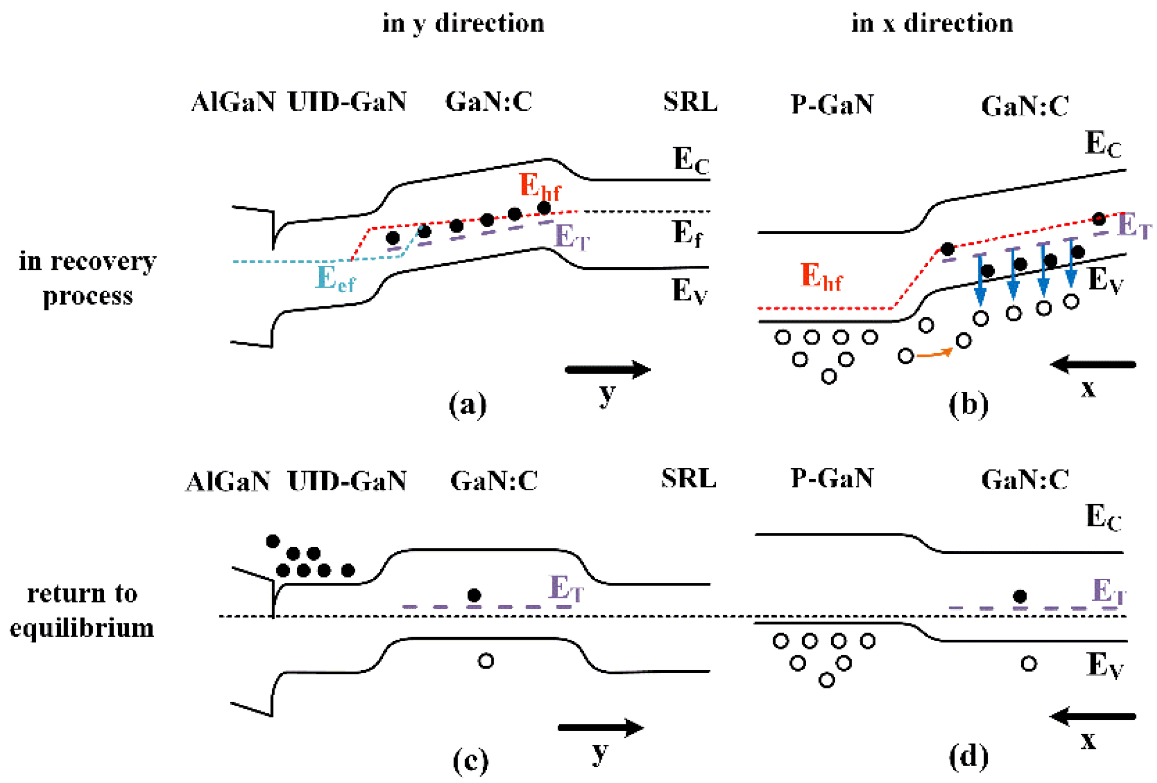
Figure 8a,b shows the schematic band diagram to illustrate differences in the recovery process of SCPG-HEMT. Right after the device was turned to on-state, the high remain potential from the ionized traps in the GaN:C buffer still depleted 2DEG, as shown in Figure 8a. Nevertheless, as shown in Figure 8b, in the x-direction, holes were injected from the SCPG to the GaN:C buffer, which was driven by the difference of hole quasi-Fermi levels, or in other words, the electric field induced by residual ionized traps in the GaN:C buffer. The drifting of holes from the p-GaN to the buffer pulled down the quasi-Fermi level in the buffer and neutralized the acceptor traps by means of recombination with the trapped electrons, as shown in Figure 8b. In addition, the sufficient supply of holes led to a much shorter dielectric relaxation time, and less time was needed to neutralize the trapped electrons. As a result, the initially depleted 2DEG recovered quickly and the whole structure returned to equilibrium, which resulted in almost-immunity to buffer-induced CC, as depicted by the uniform Fermi level in Figure 8c,d.
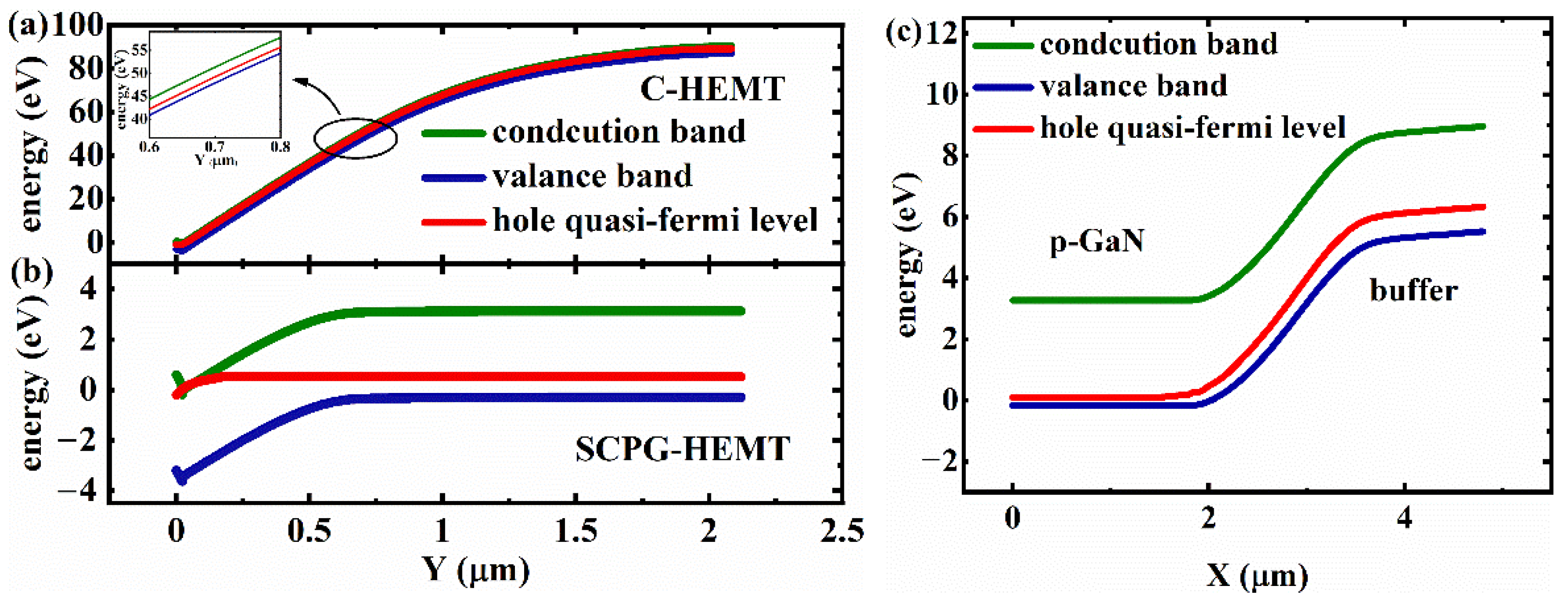
Figure 9a–c also shows the energy band diagram of C-HEMT and SCPG-HEMT from the simulation results. Figure 9a,b compares the buffer remain potential between C-HEMT and SCPG-HEMT under the drain-side gate edge 1 μs after stress. High remain potential existed in the buffer of C-HEMT after it was turned to the on-state, as depicted in Figure 5c. On the other hand, Figure 9b shows that no remain potential existed in the buffer of SCPG-HEMT and the potential stayed nearly uniform, as depicted in Figure 8c. The difference of remain potential was caused by hole injection from SCPG. Figure 9c shows the energy band diagram of SCPG and the buffer 0.1 μs after stress in the x-direction, which is in the same recovery process as in Figure 8b, when the device as just turned to the on-state after off-state stress. As shown in Figure 9c, hole is drawn into the buffer by the quasi-Fermi level difference between SCPG and the buffer. Then, the injected hole pulls down the remain potential and mitigates current collapse.
Notably, it is essential to short the p-GaN with the source electrode by a p-type ohmic contact. Figure 10a shows the distribution of holes from the SCPG, at 1 μs after switching. Those holes accumulated under the gate edge of the drain side where the electric field crowded during the off-state. Without shorting to the source electrode, the floating P-GaN is unable to suppress buffer-induced CC, as shown above in Figure 4. If the p-GaN is electrically floating, then during the recovery process the potential of p-GaN will be raised along with the GaN:C and the drift of holes will leave net-negative charged acceptors, preventing follow-up injection. It is shown in Figure 10b that the injection of holes from p-GaN to the GaN:C is prohibited with electrically floating p-GaN, which leads to no distinct improvement in CC compared with C-HEMT.

5. Conclusions

In conventional HEMTs, acceptor traps in the buffer could cause severe current collapse. After off-state stress, the hole is swept out of the buffer and the ionized acceptor traps cannot emit the captured electron by recombination with holes in the buffer. This results in negative remain potential, depleting 2DEG as a back gate during the on-state. With negligible thermal emission and huge dielectric relaxation time in the GaN buffer, the trapping effect results in current collapse with a long time constant. To minimize the buffer-induced current collapse, an SCPG-HEMT structure is proposed. When the device was switched to the on-state after off-state stress, the electric field caused by the negative remain potential in the buffer led to hole injection from the source-connected p-GaN. The injected hole quickly reduced the high remain potential by recombination with the captured electrons. Therefore, the buffer-induced current collapse could be suppressed. The mechanism of current collapse suppression in the SCPG-HEMT was illustrated by the energy band diagram.
Simulation was carried out to verify the effect of hole injection in suppressing current collapse. Comparisons are given between the SCPG-HMET and the conventional HMET in terms of DC output and transient behavior after off-state stress. Simulation results showed that SCPG-HMET can effectively suppress buffer-induced current collapse without influencing the DC output. Energy band diagrams from the simulation also show that the buffer remain potential in SCPG-HEMT is quickly reduced by means of hole injection, which was caused by hole quasi-Fermi level differences between the buffer and SCPG. In addition, the indispensability of shorting the p-GaN layer to the source was also emphasized by showing the different hole injection effects by simulation.
To realize the proposed SCPG-HEMT requires high-quality p-GaN by using a selective regrowth technique. Additionally, a clean interface between the regrowth p-GaN and the buffer is crucial for hole injection. Further research in regrowth and interface treatment is needed to realize the proposed device. This work provides a potential scheme to address the reliability issue caused by the carbon-doped buffer in high-voltage GaN electronic devices.

Author Contributions

Conceptualization, W.L. and M.W.; methodology, W.L. and M.W.; software, W.L. and H.S.; formal analysis, B.X. and W.L.; investigation, W.L. and H.S.; writing—original draft preparation, W.L.; writing—review and editing, M.W. and C.P.W.; supervision, Y.H. and B.S.; project administration, Y.H. and B.S.; All authors have read and agreed to the published version of the manuscript.

Funding

This work was supported by the National Key Research and Development Program of China under Grant 2017YFB0403000 and the National Natural Science Foundation of China under Grant 11634002 and Grant 61774002.

Data Availability Statement

The data presented in this study are available on request from the corresponding author.

Conflicts of Interest

The authors declare no conflict of interest. The funders had no role in the design of the study.

References

  1. Ishida, M.; Ueda, T.; Tanaka, T.; Ueda, D. GaN on Si technologies for power switching devices. IEEE Trans. Electron Devices 2013, 60, 3053–3059. [Google Scholar] [CrossRef]
  2. Mishra, U.K.; Parikh, P.; Wu, Y.-F. AlGaN/GaN HEMTs-an overview of device operation and applications. Proc. IEEE 2002, 90, 1022–1031. [Google Scholar] [CrossRef] [Green Version]
  3. Ikeda, N.; Niiyama, Y.; Kambayashi, H.; Sato, Y.; Nomura, T.; Kato, S.; Yoshida, S. GaN power transistors on Si substrates for switching applications. Proc. IEEE 2010, 98, 1151–1161. [Google Scholar] [CrossRef]
  4. Jiya, I.N.; Gouws, R. Overview of Power Electronic Switches: A Summary of the Past, State-of-the-Art and Illumination of the Future. Micromachines 2020, 11, 1116. [Google Scholar] [CrossRef] [PubMed]
  5. Ridley, B.K. Polarization-induced electron populations. Appl. Phys. Lett. 2000, 77, 990–992. [Google Scholar] [CrossRef]
  6. Ambacher, O.; Foutz, B. Two-dimensional electron gases induced by spontaneous and piezoelectric polarization charges in N- and Ga-face AlGaN/GaN heterostructures. J. Appl. Phys. 1999, 85, 3222–3233. [Google Scholar] [CrossRef] [Green Version]
  7. Ambacher, O.; Foutz, B.; Smart, J.; Shealy, J.R.; Weimann, N.G.; Chu, K.; Murphy, M.; Sierakowski, A.J.; Schaff, W.J.; Eastman, L.F. Two dimensional electron gases induced by spontaneous and piezoelectric polarization undoped and doped AlGaN/GaN heterostructures. J. Appl. Phys. 2000, 87, 334–344. [Google Scholar] [CrossRef]
  8. Gamarra, P.; Lacam, C.; Tordjman, M.; Splettstsser, J.; Schauwecker, B.; di Forte-Poisson, M.-A. Optimisation of a carbon doped buffer layer for AlGaN/GaN HEMT devices. J. Cryst. Growth 2015, 414, 232–236. [Google Scholar] [CrossRef]
  9. Li, X.; Bergsten, J.; Nilsson, D.; Danielsson, O.; Pedersen, H.; Rorsman, N.; Janzen, E.; Forsberg, U. Carbon doped GaN buffer layer using propane for high electron mobility transistor applications: Growth and device results. Appl. Phys. Lett. 2015, 107, 1048–1058. [Google Scholar] [CrossRef] [Green Version]
  10. Huber, M.; Silvestri, M.; Knuuttila, L.; Pozzovivo, G.; Andreev, A.; Kadashchuk, A.; Bonanni, A.; Lundskog, A. Impact of residual carbon impurities and gallium vacancies on trapping effects in AlGaN/GaN metal insulator semiconductor high electron mobility transistors. Appl. Phys. Lett. 2015, 107, 032106. [Google Scholar] [CrossRef] [Green Version]
  11. Klein, P.B.; Binari, S.C.; Ikossi, K.; Wickenden, A.E.; Koleske, D.D.; Henry, R.L. Current collapse and the role of carbon in AlGaN/GaN high electron mobility transistors grown by metalorganic vapor-phase epitaxy. Appl. Phys. Lett. 2001, 79, 3527–3529. [Google Scholar] [CrossRef]
  12. Bisi, D.; Meneghini, M.; Marino, F.A.; Marcon, D.; Stoffels, S.; Van Hove, M.; Decoutere, S.; Meneghesso, G.; Zanoni, E. Kinetics of buffer-related Ron-increase in GaN-on-Silicon MIS-HEMTs. IEEE Electron Device Lett. 2014, 35, 1004–1006. [Google Scholar] [CrossRef]
  13. Wells, A.M.; Uren, M.J.; Balmer, R.S.; Hilton, K.P.; Martin, T.; Missous, M. Direct demonstration of the ‘virtual gate’ mechanism for current collapse in AlGaN/GaN HFETs. Solid State Electron. 2005, 49, 279–282. [Google Scholar] [CrossRef]
  14. Nakajima, A.; Itagaki, K.; Horio, K. Reduction of buffer-related current collapse in field-plate AlGaN/GaN HEMTs. Phys. Status Solidi c 2009, 6, S929–S932. [Google Scholar] [CrossRef]
  15. Hashizume, T.; Ootomo, S.; Inagaki, T.; Hasegawa, H. Surface passivation of GaN and GaN/AlGaN heterostructures by dielectric films and its application to insulated-gate heterostructure transistors. J. Vac. Sci. Technol. B 2003, 21, 1828–1838. [Google Scholar] [CrossRef] [Green Version]
  16. Tang, X.; Li, B.; Zhang, Z.; Tang, G.; Chen, K.J. Characterization of static and dynamic behaviors in AlGaN/GaN-on-Si power transistors with photonic-ohmic drain. IEEE Trans. Electron Devices 2016, 63, 1–7. [Google Scholar] [CrossRef]
  17. Tanaka, K.; Morita, T.; Umeda, H.; Kaneko, S.; Kuroda, M.; Ikoshi, A.; Yamagiwa, H.; Okita, H.; Hikita, M.; Yanagihara, M. Suppression of current collapse by hole injection from drain in a normally-off GaN-based hybrid-drain-embedded gate injection transistor. Appl. Phys. Lett. 2015, 107, 163502. [Google Scholar] [CrossRef]
  18. Edwards, A.P.; Mittereder, J.A.; Binari, S.C.; Katzer, D.S.; Storm, D.F.; Roussos, J.A. Improved reliability of AlGaN-GaN HEMTs using an NH3 plasma treatment prior to SiN passivation. Ieee Electron Device Lett. 2005, 26, 225–227. [Google Scholar] [CrossRef]
  19. Lin, S.; Wang, M.; Xie, B.; Wen, C.P.; Yu, M.; Wang, J.; Hao, Y.; Wu, W.; Huang, S.; Chen, K.J.; et al. Reduction of current collapse in GaN high-electron mobility transistors using a repeated ozone oxidation and wet surface treatment. IEEE Electron Device Lett. 2015, 36, 757–759. [Google Scholar]
  20. Wang, W.; Li, L.; He, L.; Yang, F.; Chen, Z.; Zheng, Y.; He, L.; Wu, Z.; Zhang, B.; Liu, Y. Influence of AlGaN back barrier layer thickness on the dynamic ron characteristics of AlGaN/GaN HEMTs. In Proceedings of the 2016 13th China International Forum on Solid State Lighting: International Forum on Wide Bandgap Semiconductors China (SSLChina: IFWS), Beijing, China, 15–17 November 2016. [Google Scholar]
  21. Nagarajan, V.; Chen, K.-M.; Chen, B.-Y.; Huang, G.-W.; Chuang, C.-W.; Lin, C.-J.; Anandan, D.; Wu, C.-H.; Han, P.-C.; Singh, S.K. Study of Charge Trapping Effects on AlGaN/GaN HEMTs Under UV Illumination With Pulsed IV Measurement. IEEE Trans. Device Mater. Reliab. 2020, 20, 436–441. [Google Scholar] [CrossRef]
  22. Caddemi, A.; Cardillo, E.; Patanè, S.; Triolo, C. Light Exposure Effects on the DC Kink of AlGaN/GaN HEMTs. Electronics 2019, 8, 698. [Google Scholar] [CrossRef] [Green Version]
  23. Nagarajan, V.; Chen, K.-M.; Lin, H.-Y.; Hu, H.-H.; Huang, G.-W.; Lin, C.-J.; Chen, B.-Y.; Anandan, D.; Singh, S.K.; Wu, C.-H. Low-Frequency Noise Characterization of AlGaN/GaN HEMTs and MIS-HEMTs Under UV Illumination. IEEE Trans. Nanotechnol. 2020, 19, 405–409. [Google Scholar] [CrossRef]
  24. Caddemi, A.; Cardillo, E.; Salvo, G.; Patanè, S. Microwave effects of UV light exposure of a GaN HEMT: Measurements and model extraction. Microelectron. Reliab. 2016, 65, 310–317. [Google Scholar] [CrossRef]
  25. Kang, H.S.; Won, C.-H.; Kim, Y.-J.; Kim, D.-S.; Yoon, Y.J.; Kang, I.M.; Lee, Y.S.; Lee, J.-H. Suppression of current collapse in AlGaN/GaN MISHFET with carbon- doped GaN/undoped GaN multi-layered buffer structure. Phys. Status Solidi 2015, 212, 1116–1121. [Google Scholar] [CrossRef]
  26. Kim, D.S.; Won, C.H.; Kang, H.S.; Kim, Y.J.; Kim, Y.T.; Kang, I.M.; Lee, J.H. Growth and characterization of semi-insulating carbon-doped/undoped GaN multiple-layer buffer. Semicond. Ence Technol. 2015, 30, 035010. [Google Scholar] [CrossRef]
  27. Ibbetson, J.P.; Fini, P.T.; Ness, K.D.; DenBaars, S.P.; Speck, J.S.; Mishra, U.K. Polarization effects, surface states, and the source of electrons in AlGaN/GaN heterostructure field effect transistors. Appl. Phys. Lett. 2000, 77, 250. [Google Scholar] [CrossRef]
  28. Qiao, D.; Yu, L.S. Dependence of Ni/AlGaN Schottky barrier height on Al mole fraction. J. Appl. Phys. 2000, 87, 801–804. [Google Scholar] [CrossRef] [Green Version]
  29. Iwinska, M.; Piotrzkowski, R.; Litwin-Staszewska, E.; Sochacki, T.; Amilusik, M.; Fijalkowski, M.; Lucznik, B.; Bockowski, M. Highly resistive C-doped hydride vapor phase epitaxy-GaN grown on ammonothermally crystallized GaN seeds. Appl. Phys. Express 2017, 10, 011003. [Google Scholar] [CrossRef]
  30. Uren, M.J.; Karboyan, S.; Chatterjee, I.; Pooth, A.; Kuball, M. “Leaky Dielectric” model for the suppression of dynamic Ron in carbon-doped AlGaN/GaN HEMTs. IEEE Trans. Electron Devices 2017, 64, 2826–2834. [Google Scholar] [CrossRef] [Green Version]
  31. Verzellesi, G.; Morassi, L.; Meneghesso, G.; Meneghini, M.; Zanoni, E.; Pozzovivo, G.; Lavanga, S.; Detzel, T.; Haberlen, O.; Curatola, G. Influence of buffer carbon doping on pulse and AC behavior of insulated-gate field-plated power AlGaN/GaN HEMTs. IEEE Electron Device Lett. 2014, 35, 443–445. [Google Scholar] [CrossRef]
  32. Uren, M.J.; Moreke, J.; Kuball, M. Buffer design to minimize current collapse in GaN/AlGaN HFETs. IEEE Trans. Electron Devices 2012, 59, 3327–3333. [Google Scholar] [CrossRef] [Green Version]
  33. Piotrzkowski, R.; Zajac, M.; Litwin-Staszewska, E.; Bockowski, M. Self-compensation of carbon in HVPE-GaN:C. Appl. Phys. Lett. 2020, 117, 012106. [Google Scholar] [CrossRef]
  34. Zimmerman, W. Experimental verification of the Shockley--Read--Hall recombination theory in silicon. Electron. Lett. 1973, 9, 378–379. [Google Scholar] [CrossRef] [Green Version]
  35. Simmons, J.G.; Taylor, G.W. Nonequilibrium Steady-State Statistics and Associated Effects for Insulators and Semiconductors Containing an Arbitrary Distribution of Traps. Phys. Rev. B 1971, 4, 502–511. [Google Scholar] [CrossRef]
  36. Moens, P.; Vanmeerbeek, P.; Banerjee, A.; Guo, J.; Zanoni, E. On the impact of carbon-doping on the dynamic Ron and off-state leakage current of 650V GaN power devices. Proceedings of IEEE International Symposium on Power Semiconductor Devices & Ics, Hong Kong, China, 10–14 May 2015. [Google Scholar]
  37. Fariza, A.; Lesnik, A.; Neugebauer, S.; Wieneke, M.; Hennig, J.; Bläsing, J.; Witte, H.; Dadgar, A.; Strittmatter, A. Leakage currents and Fermi-level shifts in GaN layers upon iron and carbon-doping. J. Appl. Phys. 2017, 122, 025704. [Google Scholar] [CrossRef]
Figure 1. Schematic structure for the simulated (a) C-HEMT and (b) SCPG-HEMT.
Electronics 10 00942 g001
Figure 2. (a) Transfer curves of the SCPG-HEMT and the C-HEMT and (b) output characteristics of an SCPG-HEMT.
Electronics 10 00942 g002
Figure 3. Current collapse induced by buffer in (a) the C-HEMT and (b) the SCPG-HEMT.
Electronics 10 00942 g003
Figure 4. Decline of saturation current for VGS = 1 V, after stress between C-HEMT, SCPG-HEMT and PG-HEMT.
Electronics 10 00942 g004
Figure 5. Schematic band diagram of C-HEMT (a) before stress, (b) during stress, and (c) in recovery.
Electronics 10 00942 g005
Figure 6. (a) Potential distribution of C-HEMT during the off-state. (b) Remain potential in buffer, at 1 μs after off-state stress, serves as a virtual back gate.
Electronics 10 00942 g006
Figure 7. Potential distribution of SCPG-HEMT (a) during the off-state and (b) at 1 μs after off-state stress.
Electronics 10 00942 g007
Figure 8. Schematic band diagram of SCPG-HEMT (a,b) in the recovery process and (c,d) after return to equilibrium in the (a,c) y-direction and (b,d) x-direction, as labeled by x- and y-axes in Figure 7b.
Electronics 10 00942 g008
Figure 9. Buffer remain potential of (a) C-HEMT and (b) SCPG-HEMT in the y-direction 1 μs after off-state stress. (c) Energy band diagram of SCPG and buffer in the x-direction 0.1 μs after off-state stress.
Electronics 10 00942 g009
Figure 10. The distribution of holes (a) in SCPG-HEMT at a time of 1 μs after switching from an off-state to an on-state and (b) in PG-HEMT at a time of 1 μs after switching from an off-state to an on-state. It can be seen that holes from the floating p-GaN could not be injected to the GaN:C layer when p-GaN was floating.
Electronics 10 00942 g010
Table 1. Physical parameters used in the simulation.
ParametersValuesUnits
Schottky barrier height1.02eV
Polarization charge density1.1 × 1013cm–2
Hole density in SCPG5 × 1017cm–3
Mobility of 2DEG2000cm2/v·s
Mobility of electron800cm2/v·s
Mobility of hole10cm2/v·s
Source and Drain ohmic contact resistance 0.5Ω·mm
Contact resistance of p-GaN ohmic contact50Ω·mm
Trap energy level Et from valance band 0.86eV
Concentration of acceptor traps Nt5 × 1017cm–3
Capture cross section of traps1 × 10–15cm2
Degeneracy factor D of traps1-
Publisher’s Note: MDPI stays neutral with regard to jurisdictional claims in published maps and institutional affiliations.