Article

A New Active Control Driver Circuit for Satellite’s Torquer System Using Second Generation Current Conveyor

1
U. R. Rao Satellite Centre, Indian Space Research Organization (ISRO), Bangalore 560231, India
2
Department of Electronics Engineering, Indian Institute of Technology (ISM), Dhanbad 826004, India
3
School of Electronics Engineering, Kalinga Institute of Industrial Technology, Bhubaneswar 751024, India
4
Faculty of Electronics, Communication and Computers, University of Pitesti, 110040 Pitesti, Romania
5
ICSI Energy, National Research and Development Institute for Cryogenic and Isotopic Technologies, 240050 Ramnicu Valcea, Romania
6
Polytechnic University of Bucharest, 313 Splaiul Independentei, 060042 Bucharest, Romania
7
Renewable Energy Research Centre (RERC), Department of Teacher Training in Electrical Engineering, Faculty of Technical Education, King Mongkut’s University of Technology North Bangkok, 1518 Pracharat 1 Road, Wongsawang, Bangsue, Bangkok 10800, Thailand
8
Group of Research in Electrical Engineering of Nancy (GREEN), University of Lorraine, 2 Avenue de la Forêt de Haye, 54518 Vandeuvre lès Nancy, CEDEX, F-54000 Nancy, France
*
Author to whom correspondence should be addressed.
Electronics 2021, 10(8), 911; https://doi.org/10.3390/electronics10080911
Submission received: 8 March 2021 / Revised: 4 April 2021 / Accepted: 7 April 2021 / Published: 11 April 2021
(This article belongs to the Special Issue Advances in Low Power and High Power Electronics)

Abstract

:
In this article a new active control driver circuit is designed using the second-generation current conveyor for the satellite’s torquer system. The torquer plays an important role in the attitude control of the satellite. Based on the magneto-meter data, the satellite’s microprocessor calculates the required current for the torque and sends a reference command. A close loop control system is designed, which generates the desired output current. The parameters of the controller are optimized using a variant of the well-known evolutionary algorithm, the genetic algorithm (GA). This variant is known as the segmented GA. The controller is experimentally implemented using the commercially available integrated circuit, the AD844. The error between the experimental and simulation results has RMS values in range of 0.01–0.16 A for the output current and 0.41–0.6 V for the output voltage. It has mean value of 0.01 A for the output current and has mean values in the range of 0.33–0.48 V for the output voltage. It has standard deviation of 0.01 A for the output current and standard deviations in the range of 0.24–0.35 V for the output voltage. Thus, there is a close match between the simulation and experimental results, validating the design approach. These designs have many practical applications, particularly for nanosatellites powered by photovoltaic panels.

1. Introduction

A satellite’s altitude and position control are significant for its safe maneuvering that has received significant attention of the design engineers [1]. It is important to control the attitude of the satellite so that the instruments or the equipment they carry can be pointed in the desired direction [2]. There are many devices for the attitude control of a satellite, such as the thrusters, spin stabilization, momentum wheels, control moment gyros, solar sails, gravity gradient stabilization, magnetic torquers, etc. [3]. All of these attitude control devices are called “actuators.” Several factors, such as, the satellite dimensions, satellite’s operating time, satellite’s mission, etc., are to be considered for choosing an appropriate actuator.
A magnetic torquer is a simple current carrying coil that can generate the desired magnetic moment [4]. The torquer is mounted on the satellite and the interaction between the magnetic moments of the torquer and the Earth’s magnetic field produces a torque on the satellite. Thus, by controlling the resultant magnetic moment of a system of torquers it is possible to control the satellite’s attitude. Three attitude controllers were proposed in [5] based on the linear-time varying approach. Linear quadratic regulators (LQRs) were used for the stabilization of the satellite using the magnetic torquers [6]. Another optimal LQ control was proposed in [7] for achieving the attitude control of the satellite using the magnetic torquers. An extended Kalman filtering based deterministic batch algorithm was proposed by Challa et al. for the control of satellite using the measurements from the magnetometers of an Earth radiation budget satellite (ERBS) in [8]. A similar approach was proposed by the same author in [9] for the control of a spinning spacecraft. Another predictive filter was developed for the attitude control of the satellite in real-time [10]. A modified state-dependent Riccati equation was proposed in [11], where the attitude data was obtained using the magnetometers and the control was achieved using the magnetic torquers. Proportional-derivative (PD) controller based active control system was proposed in [12] for the magnetic attitude control. PD controller and an extended Kalman filter based three axis attitude control of the satellite was proposed in [13]. PD controller was also used for the attitude control of the ZDPS-1A pico-satellite using three-axis magnetic torquers [14]. Another PD controller was designed for the spacecraft stabilization, taking into account the delay between the measurement and the actuation [15]. The magneto-meter data was used for finding the magnetic torque required to stabilize a CubeSat using a detumbling algorithm [16]. A backstepping controller was proposed in [17] for the attitude control of the satellite.
The recent developments in the integrated circuit (IC) fabrication and embedded system technology contributed to the design of efficient control circuits. The modern control systems need several digital and analog circuits on a single chip that has motivated the researchers to design more efficient designs [18]. Active control circuits based on second generation current conveyors, popularly referred to as CCIIs, have been widely adopted in the past few years [19]. CCII was used for the synthesis of transfer function [20], design of filters [21], oscillators [22,23], controllers [24,25,26], etc. In [24], CCII based active control circuit was experimentally demonstrated for a physical system, whose control parameters were obtained using a series expansion method. The same series expansion method was extended for designing CCII controllers for a two-input two-output (TITO) system in [25]. A proportional-integral-derivative (PID) controller was designed using CCII and particle swarm optimization (PSO) in [26]. In this article a CCII based active control driver circuit is designed for the satellite’s torquer system, to control its attitude. The proposed driver circuit is simulated using the ORCAD Pspice and a prototype is designed using the commercially available CCII, the AD844. Moreover, the parameters pertaining to the active control circuit are obtained using the optimization algorithm, the segmented genetic algorithm (SGA).
Therefore, the novelty of this study can be summarized as follows: (1) a new active control driver is designed and tested for the satellite’s torquer system; (2) an objective function (based on the steady state error and the settling time) is proposed for the SGA algorithm to find the optimal values for the controllers’ parameters.
The manuscript is conceived in the following sections. The description of the torquer system and its modeling. This section also describes the CCII and the block diagram of the proposed controller. The third section describes the SGA, along the optimization results. These optimized parameters are used for designing the practical control circuit, whose results are reported in Section 4. Lastly, the conclusion is given at the end of the work.

2. Overview of the CCII, Torquer and the Control Arrangement

2.1. Second Generation Current Conveyor

The CCII was first introduced by Sedra and Smith in the year 1968 [27]. It has a high gain bandwidth product and it consumes less power than its voltage counterpart the operational amplifier (OPAMP) [28]. The schematic of the CCII is shown in Figure 1. It has three terminals: the input terminals are X and Y. The output terminal is Z. The relationship between the inputs and outputs is given by Equation (1) [29]. Commercially, this is available in the form of AD844 [30].
[ i y v x i z ] = [ 0 0 0 1 0 0 0 ± 1 0 ] [ v y i x v z ]

2.2. Torquer System and its Modeling

The torquer is responsible for the attitude control of the satellite. The satellite’s onboard micro-controller takes the measurement data from the magneto-meters and generates the reference command that is fed as an input to the torquer’s driver circuit. The output of the driver circuit is fed to the torquer, which controls the satellite’s attitude.
The desired torque is generated by passing the required electric current through the torquer by applying a voltage across it. Thus, it is necessary to study the relationship between the voltage applied to the torquer and the current flowing through it. The torquer coil has some specific resistance R and an inductance L. Thus, the torquer can be modeled as a series RL circuit as shown in Figure 2. The electric current response to the applied voltage is specified by the transfer function given by Equation (2).
I ( s ) = 1 R + s L V i n ( s )
The torquer used for the present work belongs to a nanosatellite and has the parameters that are shown in Table 1. The active control circuit designed in this manuscript is for this torquer. However, the approach developed in this manuscript is applicable for any other torquer system. Based on these parameters, the transfer function of the torquer used for this study is given by Equation (3).
I ( s ) = 1 38 + 0.018 s V i n ( s )

2.3. Generalized Control Block Diagram

A basic control arrangement is shown in the Figure 3, where the control circuit controls the system to give the desired output based on the reference command input.
The same concept is used in this article to control the current in the torquer system. A driver is designed for the supervisory control of the torquer system’s current. This can be an open loop or closed loop control. In most of the satellites, linear control is used for achieving the attitude control using the torquer. For linear control, the architecture shown in Figure 4 is proposed for controlling the torquer system.
Two proportional controllers are used: one in the forward loop (K1) and the other in the feedback loop (K2) for the closed loop control. An open loop control can be achieved by removing the proportional controller in the feedback loop. The parameters of the proportional gains in the forward loop and the feedback loop are obtained using the SGA and these controllers are implemented using the CCIIs.
For the control of the torquer system, the advantages of using CCII as compared to the operational amplifier (OPAMP) are:
  • CCII architecture offers better performance, high linearity, and an exceptionally clean pulse response when compared to the OPAMP.
  • With the CCII, the closed-loop bandwidth is determined primarily by the feedback resistor and is almost independent of the closed-loop gain. It is also free from the slew rate limitations inherent in traditional OPAMPs. Additionally, in the OPAMP, the bandwidth is limited by the gain.
  • With CCII feedback is in the form of current. CCII responds to an error current at one of its input terminals, rather than an error voltage (as in OPAMP) and produces a corresponding output voltage.

3. Segmented Genetic Algorithm

This genetic algorithm (GA) is a widely used evolutionary optimization algorithm [31]. In GA an initial population containing of several individuals is taken that are encoded as chromosomes. These chromosomes evolve over a certain number of generations. This evolution is based on the following processes:
  • Selection: This is the first step in which few individuals are selected from the previous generation based on the fitness value. This fitness value is a measure of how close the individual is to the optimum value.
  • Crossover: This is the second step in which the individuals selected in the previous step are used for generating the offspring.
  • Mutation: This step is the last step in which the individuals are randomly mutated.
These three steps are repeated over several generations and the individuals evolve continuously. Numerous variants of GA have been proposed to improve its performance. Segmented GA (SGA) is one such technique whose superior performance has been demonstrated [32].
In the SGA, the chromosome set is divided into two sets: set 1 and set 2. These two sets of chromosomes are alternatively optimized. The flowchart of this technique is shown in Figure 5.
The parameters of the proportional controllers shown in Figure 4 were obtained using the SGA. As the system is a first order system and the controller is of proportional type, there is no overshoot in the output. Therefore, the criterion is to reduce the steady state error and the settling time. The objective function is given below:
F = s 2 + e 2
where s is the settling time and e is the steady state error. To demonstrate the efficacy of the proposed algorithm, its performance is compared with that of the GA, PSO, firefly algorithm (FA), and bat algorithm (BA). All the algorithms are initialized with the following parameters: maximum iterations: 30; number of variables: 2; size of the population: 10. The other parameters of these algorithms are given in Appendix A. No special effort was taken in fine tuning the parameters of the various algorithms. These optimization algorithms were implemented in MATLAB and the optimized parameters of the controllers were obtained by minimizing the cost function given in Equation (4) using these algorithms. The step responses obtained using these algorithms are shown in the Figure 6 and the comparison of different optimization techniques in terms of settling time and steady state error are shown in Table 2.
From the figure and from the results shown in Table 2, it can be clearly observed that the SGA with 10 segments is better than the other algorithms in terms of reducing the steady state error. We can also observe that some of the algorithms perform better than the GA, but their performance is still inferior to that of the SGA with 10 segments. Additionally, it can be observed that the number of segments affects the performance of the SGA. By proper choice of this parameter, we can improve the optimization performance. The parameters of the proportional gains obtained using the SGA are K1 = 22.94 and K2 = 23.45.

4. Control Driver Circuit Design

The control circuits based on the optimized values obtained in the previous section are designed using the CCIIs. The control driver circuit in the closed loop architecture is shown in the Figure 7. The current flowing through the torquer is sensed using the sense resistor. This information is again fed back as a negative feedback to ensure the required current in the torquer system. By changing the tunable resistance R3, three different operational ranges can be selected as follows: 15 V (400 mA), 25 V (650 mA), and 40 V (1 A). Simulation and experimental validations are obtained for all three operational ranges.
The circuit shown in the Figure 8 is the equivalent of the close loop control circuit. As in the previous section, it is already explained that the transistors Q1 and Q2 are only used to provide the current gain (β).
Based on the command voltage signal, the driver circuit will give a small output current, which will be amplified by the current gain (β), thereby delivering the desired current to the torquer. For deriving the transfer function model, the various parameters that will be used are shown in the Figure 8. The following are the equations for deriving the transfer function model:
{ i y = 0 v x = v y = v i n i z = i x } & { i y f = 0 v x f = v y f = v s i x f = i z f }
i x = v f v i n R 1 v i n v L R 2
v i n [ 1 R 1 + 2 R 2 ] = v f R 1 + v L [ 1 R L + 2 R 2 ]
i x f = v f v s R 4 v s R 3
i z f = v s v f R 4 v f v i n R 1
i L = [ 1 R 4 + 1 R 2 + 2 R 1 R 2 R 4 1 2 + R 1 R 4 + R L R 2 + 2 R 1 R 2 R 2 R 4 ] v i n [ 1 R 3 + 2 R 4 1 + 2 R 1 R 4 + 2 R L R 2 + 4 R 1 R 2 R 2 R 4 ] v s f
i L f = β · i L & v s = R 6 R 5 + R 6 · v s f
I L f = β [ 1 R 4 + 1 R 2 + 2 R 1 R 2 R 4 1 2 + R 1 R 4 + R L R 2 + 2 R 1 R 2 R 2 R 4 ] V i n [ β ( 1 R 3 + 2 R 4 ) ( R 6 R 5 + R 6 ) 1 + 2 R 1 R 4 + 2 R L R 2 + 4 R 1 R 2 R 2 R 4 ] V s f
Equation (12) shows that the final load current depends on the input voltage and the feedback voltage. For a given reference input, the required current will flow in the load. The increase or decrease in the load current due to the noise will be compensated by the feedback voltage, and thus, the desired current will flow in the torquer system.

5. Simulations and Experimental Results

The active control circuit was assembled on a breadboard and the prototype was tested on the torquer system. The CCII was implemented using the AD844 IC, transistor Q1 is NPN 2N3701, transistor Q2 is the PNP 2N5679 and the transistor Q is the NPN 2N5672. Both the control circuit and the torquer are shown in Figure 9.
The various parameters of the resistors satisfying the proportional gains obtained using the SGA were selected based on the equations derived above and these values are reported in Table 3, for different operational voltages.
The control circuit was simulated using the ORCAD Pspice software and AD844 IC was used for the CCII. ORCAD is a proprietary software belonging to Cadence design systems, widely used for electronic circuit simulation and verification.

5.1. Results for 15 V, 400 mA

In nanosatellites the processor works on 3.3 V, so the output current that will flow in the load varies from 0 to 400 mA against the reference input of 0–3.3 V. The output voltage will increase from 0 to 15V. If the input is increased beyond 3.3V, the output current will saturate to 400 mA. The output voltage saturates to 15 V. The simulation and the experimental results are shown in the Figure 10.

5.2. Results for 25 V, 650 mA

In this case, so the output current that will flow in the load varies from 0 to 650 mA against the reference input of 0–3.3 V. The output voltage will increase from 0 to 25 V. If the input is increased beyond 3.3 V, the output current will saturate to 650 mA and the output voltage saturates to 25 V. The simulation and the experimental results are shown in Figure 11.

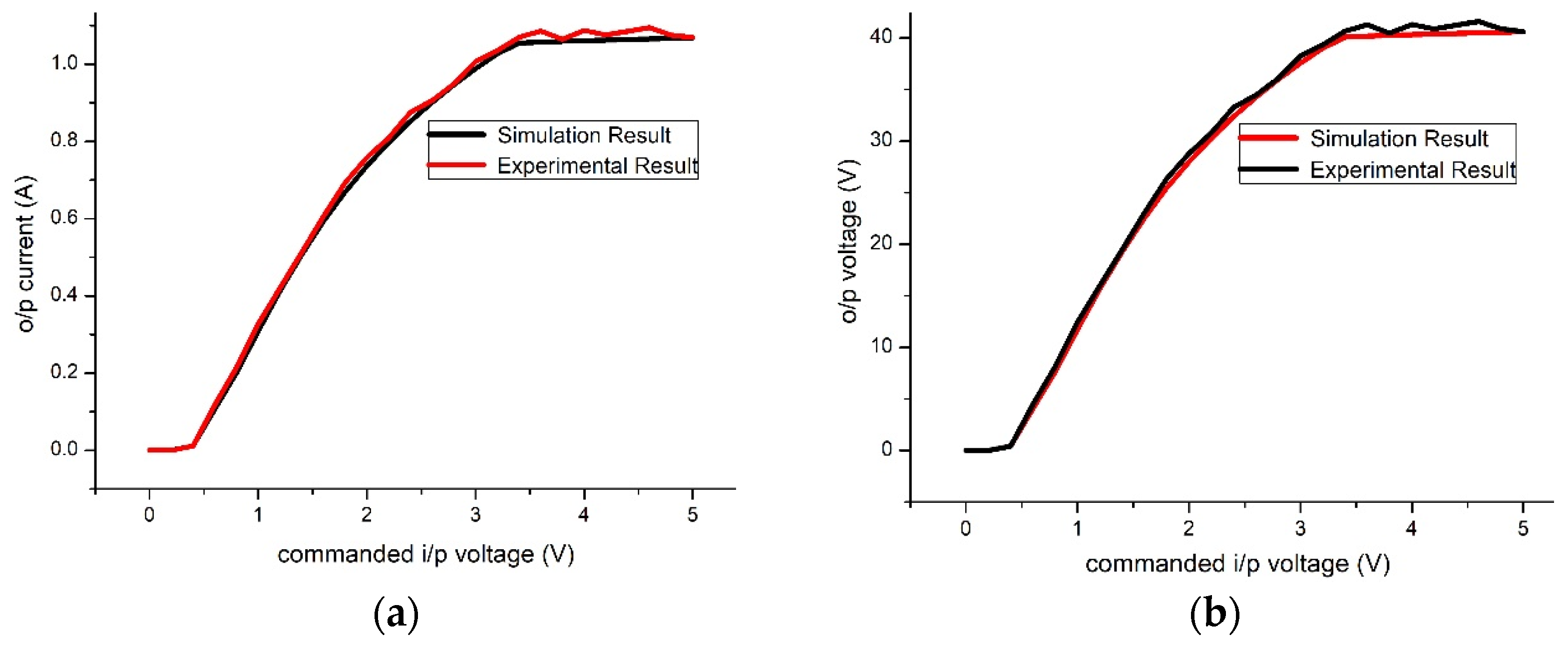
5.3. Results for 40 V, 1 A

In this case, so the output current that will flow in the load varies from 0 to 1 A against the reference input of 0–3.3 V. The output voltage will increase from 0 to 40 V. If the input is increased beyond 3.3 V, the output current will saturate to 1 A and the output voltage saturates to 40 V. The simulation and the experimental results are shown in Figure 12.
It can be observed from the above figures that the linearity of the experimental output is good, because of the tolerances on the printed circuit board (PCB). For the 25-volt operation, in transistor Q, small base current (in the range of uA) results in high emitter load current (mA). In practice, to maintain a constant base is difficult. Therefore, even a small base current change (due to fluctuations or noise) can lead to sufficient emitter current, which in turns leads to change in emitter voltage. Due to this reason the experimental output voltage exceeds 25 V and the experimental output current exceeds 650 mA. For the 40-volt operation, the load current requirement is high. Due to this, the transistor Q’s base current is also high and thus, its operation region shifts from the linear region towards the saturation region. This reduces the linear range of operation.
For qualitative assessment of the results, the error between the experimental and the simulation results was analyzed. It was observed that the RMS error is in range of 0.01–0.16 A for output current and 0.41–0.6 V for output voltage. The error has mean value of 0.01 A for the output current and has mean values in the range of 0.33–0.48 V for the output voltage. It also has standard deviation of 0.01 A for the output current and standard deviations in the range of 0.24–0.35 V for the output voltage. Furthermore, it was also observed that the RMS error, the mean error, and the standard deviation in the error for 25 and 40 V operations are almost similar.

6. Conclusions

Magnetic torquers are widely used for the attitude control of satellites. Kalman filters, PD controllers, etc., were adopted by the researchers for controlling the current flowing through the torquer, using the reference command received from the microprocessor. In this article an active control driver was designed for controlling the torquer’s current.
The main findings of this study are as follows: (1) the new active control driver was designed using CCIIs and tested for three operation ranges; (2) the optimal values for the controller parameters were obtained using the SGA algorithm; (3) the experimental results are in good agreement with the simulation results, the RMS errors being in range of 0.01–0.16 A for output current and 0.41–0.6 V for output voltage. The error has mean value of 0.01 A for the output current and has mean values in the range of 0.33–0.48 V for the output voltage. It also has standard deviation of 0.01 A for the output current and standard deviations in the range of 0.24–0.35 V for the output voltage.
These obtained results indicate that the design presented can be practically employed for space applications. The authors intend to develop artificial intelligence methods for the attitude of the satellite based on the measurements obtained from the magneto-meters, in their future research and compare the results obtained by using the proposed method of attitude control with other methods of attitude control proposed in the literature [33].

Author Contributions

Research methodology, V.K.V., R.K.R., P.P. and B.A.; writing—original draft preparation, V.K.V., R.K.R. and P.P.; supervision, R.K.R., P.T. and N.B.; validation, B.A. and N.B.; writing—review and editing, V.K.V., B.A., N.B. and P.T. All authors have read and agreed to the published version of the manuscript.

Funding

This work was partially supported by the International Research Partnerships: Electrical Engineering Thai-French Research Center (EE-TFRC) between King Mongkut’s University of Technology North Bangkok and University of Lorraine under Grant KMUTNB−BasicR−64−17.

Conflicts of Interest

The authors declare no conflict of interest.

Appendix A

GA Parameters: Population size = 10, number of generations = 30
SGA Parameters: Population size = 10, number of generations = 30
FA Parameters: No. of fireflies: 10, α (randomness) = 0.5, β0 (attractiveness) = 1, γ (absorption) = 1, No. of Iteration: 30
PSO Parameters: Number of particles= 10, number of iterations = 30
BA Parameters: Population size = 10, No. of iteration = 30, A (loudness) = 1, α = 1, γ = 0.1

References

  1. Duan, G.R.; Yu, H.H. LMIs in Control Systems—Analysis Design and Applications; CRC Press, Taylor & Francis Group: Boca Raton, FL, USA, 2013; pp. 37–389. [Google Scholar]
  2. Wei, L.; Yongliang, X.; Haibo, Y. The effect of satellite movement on two-way time synchronization performance. In Proceedings of the 2012 IEEE International Frequency Control Symposium Proceedings, Baltimore, ML, USA, 21–24 May 2012; Institute of Electrical and Electronics Engineers (IEEE): Piscataway Township, NJ, USA, 2012; Volume 21, pp. 1–3. [Google Scholar]
  3. Sidi, M.J. Spacecraft Dynamics and Control—A Practical Engineering Approach; Cambridge University Press: England, UK, 1997; pp. 64–111. [Google Scholar]
  4. Söken, H.E. An Attitude Filtering and Magnetometer Calibration Approach for Nanosatellites. Int. J. Aeronaut. Space Sci. 2018, 19, 164–171. [Google Scholar] [CrossRef]
  5. Wisniewski, R. Linear Time-Varying Approach to Satellite Attitude Control Using Only Electromagnetic Actuation. J. Guid. Control. Dyn. 2000, 23, 640–647. [Google Scholar] [CrossRef] [Green Version]
  6. Psiaki, M.L. Magnetic Torquer Attitude Control via Asymptotic Periodic Linear Quadratic Regulation. J. Guid. Control. Dyn. 2001, 24, 386–394. [Google Scholar] [CrossRef]
  7. Lovera, M.; De Marchi, E.; Bittanti, S. Periodic attitude control techniques for small satellites with magnetic actuators. IEEE Trans. Control. Syst. Technol. 2002, 10, 90–95. [Google Scholar] [CrossRef] [Green Version]
  8. Challa, M.; Kotaru, S.; Natanson, G. Magnetometer-only attitude and rate estimates during the Earth Radiation Budget Satellite 1987 control anomaly. In Proceedings of the Guidance, Navigation, and Control Conference, Hilton Head, SC, USA, 10–12 August 1997; American Institute of Aeronautics and Astronautics: Reston, VA, USA, 1997; Volume 2, pp. 830–840. [Google Scholar]
  9. Challa, M.; Natanson, G.; Ottenstein, N. Magnetometer-only attitude and rate estimates for spinning spacecraft. In Proceedings of the Astrodynamics Specialist Conference, Denver, CO, USA, 14–17 August 2000; American Institute of Aeronautics and Astronautics: Reston, VA, USA, 2000; pp. 311–321. [Google Scholar]
  10. Crassidis, J.L.; Markley, F.L. Predictive Filtering for Attitude Estimation Without Rate Sensors. J. Guid. Control. Dyn. 1997, 20, 522–527. [Google Scholar] [CrossRef] [Green Version]
  11. Abdelrahman, M.; Park, S.-Y. Integrated attitude determination and control system via magnetic measurements and actuation. Acta Astronaut. 2011, 69, 168–185. [Google Scholar] [CrossRef] [Green Version]
  12. Ovchinnikov, M.; Roldugin, D.; Penkov, V. Three-axis active magnetic attitude control asymptotical study. Acta Astronaut. 2015, 110, 279–286. [Google Scholar] [CrossRef]
  13. Ivanov, D.; Ovchinnikov, M.; Penkov, V.; Roldugin, D.; Doronin, D.; Ovchinnikov, A. Advanced numerical study of the three-axis magnetic attitude control and determination with uncertainties. Acta Astronaut. 2017, 132, 103–110. [Google Scholar] [CrossRef]
  14. Xiang, T.; Meng, T.; Wang, H.; Han, K.; Jin, Z.-H. Design and on-orbit performance of the attitude determination and control system for the ZDPS-1A pico-satellite. Acta Astronaut. 2012, 77, 182–196. [Google Scholar] [CrossRef]
  15. Celani, F. Spacecraft Attitude Stabilization Using Magnetorquers with Separation Between Measurement and Actuation. J. Guid. Control. Dyn. 2016, 39, 2184–2191. [Google Scholar] [CrossRef]
  16. Carletta, S.; Teofilatto, P. Design and Numerical Validation of an Algorithm for the Detumbling and Angular Rate De-termination of a CubeSat Using Only Three-Axis Magnetometer Data. Int. J. Aerosp. Eng. 2018, 3, 1–12. [Google Scholar] [CrossRef]
  17. Giri, D.K.; Sinha, M. Robust Backstepping Magnetic Attitude Control of Satellite Subject to Unsymmetrical Mass Properties. J. Spacecr. Rocket. 2019, 56, 298–305. [Google Scholar] [CrossRef]
  18. Safari, L.; Minaei, S. A simple low voltage, high output impedance resistor based current mirror with extremely low input and output voltage requirements. In Proceedings of the 2016 39th International Conference on Telecommunications and Signal Processing (TSP), Vienna, Austria, 27–29 June 2016; Institute of Electrical and Electronics Engineers (IEEE): Piscataway Township, NJ, USA, 2016; pp. 254–256. [Google Scholar]
  19. Sedra, A.S. The current conveyor: History and progress. In Proceedings of the 2015 IEEE International Symposium on Circuits and Systems (ISCAS), Lisbon, Portugal, 24–27 May 2015; Institute of Electrical and Electronics Engineers (IEEE): Piscataway Township, NJ, USA, 2015; pp. 1567–1571. [Google Scholar]
  20. Toumazou, C.; Lidgey, F.J.; Haigh, D.G. Analogue IC Design: The Current Mode Approach; Peter Peregrinus Ltd.: London, UK, 1992. [Google Scholar]
  21. Aronhime, P. Transfer-function synthesis using a current conveyor. IEEE Trans. Circuits Syst. 1974, 21, 312–313. [Google Scholar] [CrossRef]
  22. Abdalla, K.K.; Bhaskar, D.R.; Senani, R. Configuration for Realizing a Current-Mode Universal Filter and Dual-Mode Quadrature Single Resistor Controlled Oscillator. IET Circuits Devices Syst. 2012, 6, 159–167. [Google Scholar] [CrossRef]
  23. Senani, R.; Bhaskar, D.R.; Singh, V.K.; Sharma, R.K. Sinusoidal Oscillators and Waveform Generators using Modern Electronic Circuit Building Blocks; Springer: Cham, Switzerland, 2016; pp. 175–209. [Google Scholar]
  24. Gupta, P.; Verma, V.K.; Ranjan, R.K.; Appasani, B.; Priyadarshini, B.; Nath, V. A series expansion method aided design of current mode second generation current conveyor based active control circuit. Microsyst. Technol. 2018, 25, 2323–2330. [Google Scholar] [CrossRef]
  25. Verma, V.K.; Ranjan, R.K.; Gupta, P.; Priyadarshini, B.; Nath, V. A Series Expansion Method Aided Design of CCII Controller for a Tito System. Microsyst. Technol. 2018, 24, 3843–3849. [Google Scholar] [CrossRef]
  26. Gupta, P.; Appasani, B.; Verma, V.K.; Ranjan, R.K. PSO based CCII PID controller for a continuous stirred tank reactor system. In Proceedings of the 2017 IEEE International Conference on Power, Control, Signals and Instrumentation Engineering (ICPCSI), Chennai, India, 21–22 September 2017; Institute of Electrical and Electronics Engineers (IEEE): Piscataway Township, NJ, USA, 2017; pp. 2786–2789. [Google Scholar]
  27. Verma, V.K.; Ranjan, R.K.; Lekshmi, V.; Azad, A.K.; Appasani, B.; Nath, V. A second generation current conveyor based PID controller optimized using a crossover improved genetic algorithm. Microsyst. Technol. 2020, 26, 1449–1454. [Google Scholar] [CrossRef]
  28. Smith, K.; Sedra, A. The current conveyor—A new circuit building block. In Proceedings of the Proceedings of the IEEE; Institute of Electrical and Electronics Engineers (IEEE): Piscataway Township, NJ, USA, 1968; Volume 56, pp. 1368–1369. [Google Scholar]
  29. Wilson, B. Recent developments in current conveyors and current-mode circuits. IEE Proc. G Circuits, Devices Syst. 1990, 137, 63. [Google Scholar] [CrossRef]
  30. Svoboda, J.A.; McGory, L.; Webb, S. Applications of a commercially available current conveyor. Int. J. Electron. 1991, 70, 159–164. [Google Scholar] [CrossRef]
  31. Goldberg, D.E. Genetic Algorithms; Pearson Education: New Delhi, India, 2006; pp. 1–25. [Google Scholar]
  32. Appasani, B.; Gupta, N. A Novel Segmentation Approach in GA and its Applications in Antenna Arrays. Microw. Rev. 2017, 23, 8–14. [Google Scholar]
  33. Smeresky, B.; Rizzo, A.; Sands, T. Optimal Learning and Self-Awareness Versus PDI. Algorithms 2020, 13, 23. [Google Scholar] [CrossRef] [Green Version]
Figure 1. Block diagram of current conveyor.
Electronics 10 00911 g001
Figure 2. Basic model of torquer system.
Electronics 10 00911 g002
Figure 3. Control system block diagram.
Electronics 10 00911 g003
Figure 4. Proposed architecture for the control of torquer’s current mode.
Electronics 10 00911 g004
Figure 5. Flowchart of the proposed segmented genetic algorithm (SGA).
Electronics 10 00911 g005
Figure 6. Step response using several optimization techniques. FA: firefly algorithm; BA: bat algorithm; PSO: particle swarm optimization.
Electronics 10 00911 g006
Figure 7. Control driver circuit in closed loop configuration.
Electronics 10 00911 g007
Figure 8. Equivalent of the close loop control circuit.
Electronics 10 00911 g008
Figure 9. Experimental set-up: (a) control circuit; (b) torquer system.
Electronics 10 00911 g009
Figure 10. The 15 V operation (a) Output; current (b) Output voltage.
Electronics 10 00911 g010
Figure 11. The 25 V operation (a) Output current; (b) Output voltage.
Electronics 10 00911 g011
Figure 12. The 40 V operation (a) Output current; (b) Output voltage.
Electronics 10 00911 g012
Table 1. Parameters of the torquer used in this study.
ParameterValue
Magnetic dipole moment, Am20.15
Coil resistance, Ohm38
Coil inductance, mH18
Number of turns370
Table 2. Comparison of different optimization techniques.
Optimization TechniqueSettling Time (ms)Steady-State Error (%)
GA0.18610%
SGA (2 segments)0.20310.9%
SGA (6 segments)0.1417.6%
SGA (10 segments)0.1226.6%
PSO0.1518.1%
FA0.168.6%
BA0.22712.3%
SGA: segmented genetic algorithm; GA: genetic algorithm.
Table 3. Resistance values for all three-voltage operations.
ResistanceValue
15 Volt Operation25 Volt Operation40 Volt Operation
R16.8 kΩ6.8 kΩ6.8 kΩ
R232 kΩ32 kΩ32 kΩ
R3100 Ω220 Ω500 Ω
R46.8 kΩ6.8 kΩ6.8 kΩ
Publisher’s Note: MDPI stays neutral with regard to jurisdictional claims in published maps and institutional affiliations.

