Abstract
In the present study, the layout structure of an n-MOSFET, which is vulnerable to radiation, was designed in a different way to enhance its tolerance to radiation. Radiation damage assessment was conducted using modeling and simulation (M&S) techniques before actual semiconductor process fabrication and radiation tests to verify its tolerance properties. Based on the M&S techniques, the role of each layer was determined to improve the radiation tolerance of semiconductors, and the layout design of an n-MOSFET with enhanced radiation tolerance was optimized. The optimized radiation-tolerant n-MOSFET design was implemented in the 0.18-um CMOS bulk process, and radiation exposure tests were conducted on the device. A cumulative radiation dose up to 2 Mrad(Si) was applied to verify its radiation-tolerant performance. Developing new devices using M&S techniques for radiation damage assessment allows reliable estimates of their electrical and radiation-tolerant properties to be obtained in advance of the actual manufacturing process, thereby minimizing development costs and time.
1. Introduction
As the fourth industrial revolution expands worldwide, the demand for special-purpose semiconductors continues to grow, especially in fields such as advanced aerospace and nuclear power industries. Electronic devices that are used in nuclear power and space industries, as well as medicine, unmanned aircraft, and autonomous driving, are subjected to a total ionizing dose (TID), caused by exposure to radiation. Semiconductors composed of silicon-based complementary metal–oxide–semiconductor (CMOS) devices, in particular, are easily affected by radiation-induced leakage currents, and this often leads to overall performance degradation. The CMOS integrated circuits (ICs) that perform various functions such as amplification, comparison, data conversion and storage, and stable voltage supply in the latest electronic systems, are required to have high-performance (high speed and high resolution) and high-integration characteristics. However, advanced ICs in a radiation environment are limited to increasing the operating speed and the precision due to the degradation of the CMOS device. In the worst case, ICs can lose function due to accumulated radiation and cause serious social/environmental problems such as radiation exposure and contamination [1,2,3,4,5,6,7,8].
Given that the safety of nuclear reactors and aircraft directly affects human lives, the radiation-tolerant design of semiconductor parts in their internal electronic systems is considered essential. This is also the case in medical applications. Mistakes in calculating the radioactivity of therapeutic radiation sources, malfunctions in X-ray devices and accelerators, or excessive radiation exposure during diagnosis and treatment could cause the intended dose to be exceeded, or lead to radiation accidents. In unmanned aircraft and autonomous driving fields, malfunctions or obstacle detection failures, which are often caused by data errors, may lead to serious consequences including the loss of lives [3,4,5,6,7,8].
CMOS semiconductors have various parameters that make them sensitive to radiation, such as the presence of impurities, and electric fields, as well as the characteristics and geometry of the silicon and oxide materials. This makes it very difficult to analyze the combined effects of such factors. Many attempts have been made to find ways to improve the radiation-tolerant properties of these semiconductors. Recently, considerable research attention has been focused on structural modifying to enhance the radiation tolerance of n-MOSFETs, which are particularly affected by cumulative radiation doses. The research is accomplished by process layout modification, an approach that does not require any additional circuits, logic (speed reduction and area increase) [9,10], or process masks (higher costs) [11]. Radiation tolerance can be achieved just by adding new layers or modifying existing layers, while maintaining the existing CMOS process procedures [12,13,14,15,16].
In previous research, efforts to improve radiation tolerance have focused on making various modifications to an existing MOSFET structure and performing radiation tests on them. Instead, the present study employed modeling and simulation (M&S) techniques for radiation damage assessment, which can predict the effect of radiation on semiconductor devices in advance, in a more efficient manner. This approach could accelerate progress in research to improve the radiation tolerance of semiconductors [17,18].
Using these M&S techniques, the role of each layer in improving the radiation tolerance of semiconductors was investigated, and the design layout of an n-MOSFET with enhanced radiation tolerance was optimized. The optimized radiation-hardened (RH) n-MOSFET design was implemented in a 0.18-um CMOS process. To verify its radiation-tolerant performance, radiation exposure tests then were conducted on the device chip while the dose was increased up to a cumulative radiation of 2 Mrad(Si). The tests were conducted at the high-level gamma-ray irradiation facility of the Advanced Radiation Technology Institute (ARTI) in Korea.
2. M&S Verification of Semiconductor Damage by Radiation
This section describes how M&S techniques were practically employed to assess the radiation damage to semiconductors with radiation dose, using the radiation-induced damage mechanism of semiconductors. The equations used for the characteristic modeling of 3D TCAD-based semiconductor devices are Poisson’s equation, the carrier continuity equations, the transport equations (drift-diffusion transport model and energy balance transport Model), and the displacement current equation.
The most suitable layers, structures, and properties for improving the radiation tolerance of semiconductor devices were determined, and the structural design was modified in various patterns. Many of the previous studies on radiation tolerance improvement have been limited when attempting structural modifications because prototypes must be repeatedly fabricated to conduct tests to verify the radiation tolerance performance of the structural patterns being designed. In contrast, one of the important advantages of the M&S techniques utilized in the present study is that multiple attempts can be made as desired in the virtual environment.
2.1. Cumulative Radiation-Induced Damage to MOSFETs
The total ionizing dose (TID) effect is one of the main causes of damage to silicon-based electronic devices It refers to the phenomenon where ionizing radiation-induced damage is long-term accumulated in electronic devices. This leads to their gradual performance degradation. Radiation has much greater energy than the bandgap of silicon dioxide and thus causes electron/hole pairs (EHPs) to be generated in the silicon dioxide layers. The movement of these EHPs is then determined by the bias applied to the gate. Generally, a positive bias is applied to the gate in n-MOSFETs, and this causes the electrons to move towards the gate electrode and the holes to move towards the silicon bulk. While the electrons are able to escape the silicon dioxide layers because they are highly mobile in the layers, few mobile holes travel across localized states inside the bandgap of the silicon dioxide layers and finally reach the Si-SiO2 interfaces, where they are trapped. These trapped holes are called fixed charges. When radiation-induced fixed charges are generated in the oxide film layers of an n-MOSFET whose majority carriers are electrons, these fixed positive charges induce a channel inversion between the source and the drain, thereby causing the formation of leakage current paths, as shown in Figure 1 [19,20,21,22].
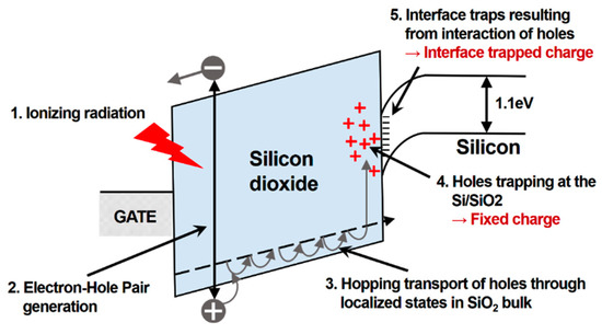
Figure 1.
Radiation-induced fixed charges in the n-MOSFET caused by total ionizing dose (TID) effect.
In the semiconductor manufacturing process, the oxide film layers of an n-MOSFET are divided into isolation oxide films for electrically isolating individual devices, and gate oxide films. In the existing 1 um-plus process, radiation-induced fixed charges can be generated in the gate oxide films, which may lead to a variety of unexpected problems. In the 0.5 um or less deep sub-micron process, however, the thickness of the gate oxide in the bulk CMOS process is set to a value of less than 10 nm. The gate oxide thickness of the 0.18-um CMOS STI process is about 4 nm, and 0.35-um CMOS LOCOS process is about 7 nm. According to previous reports, oxide films with a thickness of less than 10 nm allow the holes to be removed through tunneling, thus significantly reducing variations in the threshold voltage. Therefore, such gate oxide films were no longer considered a major concern in the process [23,24]. In contrast, hundreds-of-nanometer-thick isolation oxides generate fixed charges, which may inflict radiation damage and thus critically degrade the performance of each device. Therefore, shutting down these leakage current paths is a prerequisite to improving the radiation tolerance of the n-MOSFET structure against the TID effect.
2.2. Structural Design of Radiation-Tolerant Layout
As shown in Figure 2, the following structures were designed for each pattern to conduct the M&S of radiation damage to typical n-MOSFET layout structures: (a) a standard structure to identify radiation damage; (b) an extended gate poly structure to minimize damage; (c) a structure in which the n-active region is overlapped with the p-active region, and a p+ doping region is introduced; (d) the combined structure of (b) and (c); and (e) the same structure as (d) except that the n-active region is not overlapped with the p-active region.
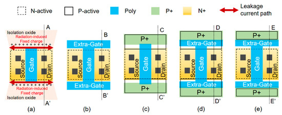
Figure 2.
Radiation-tolerant pattern-specific n-MOSFET layout structures: (a) the standard structure; (b) the extended gate poly structure; (c) the structure to which the p-active and p+ doping regions are added; (d) the combined structure of (b,c); and (e) the same structure as (d) except that the n-active region is not overlapped with the p-active region.
Improving radiation tolerance requires minimization of the effect of the radiation-induced fixed charges present in the isolation oxide film layers. Therefore, we basically focused on the structure that can change the position of the insulation oxide films and designed various structures for each pattern in order to secure a structure that does not affect the n+ region (source and drain). This must be achieved by modifying the layout while at the same time maintaining the intrinsic electrical characteristics of the standard structure. Based on semiconductor manufacturing procedures, isolation oxide films will be formed everywhere except for the active region. The cross-sectional views of each structure are presented in Figure 3.
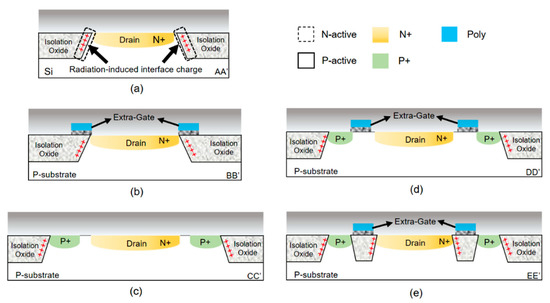
Figure 3.
Cross-sectional views of the pattern-specific n-MOSFETs: (a) the standard structure; (b) the extended gate poly structure; (c) the structure to which the p-active and p+ doping regions are added; (d) the combined structure of (b,c); and (e) the same structure as (d) except that the n-active region is not overlapped with the p-active region.
In Structure (a) (standard structure), the fixed charges are trapped at the isolation oxide film-silicon interfaces where sources and drains are formed. In Structure (b), even if the gate poly is extended, the position of the formation of isolation oxide films remains the same during the semiconductor manufacturing process. In Structure (c), p-active and p+ doping regions are added to the source/drain n+ region in a perpendicular direction, and thus the active region is extended. As a result, the position of the formed isolation oxide films is shifted out of the active region. Here, the p+ region remains in a floating state or 0 V voltage is applied to the region. In Structure (d), the gate poly is combined with the p-active and p+ doping regions, and thus the position of the formed isolation oxide films is changed. The gate poly is formed between the p+ and n+ regions on top of the active region [25].
2.3. Using M&S to Assess Radiation Effect
M&S was performed on each structure of the n-MOSFETs to which layout modifications had been applied, as described in Section 2.2, to determine the effect of radiation on them. The effect of cumulative radiation-induced TID on the n-MOSFET intensifies over time because cumulative doses increase, and more and more EHPs are generated over time. This leads to an increase in the number of charges trapped at the isolation oxide film-silicon interfaces. Accordingly, the majority carrier electrons of the n-MOSFET end up forming leakage current paths at the interfaces [26]. A 3D radiation-induced damage model was designed based on this damage mechanism, i.e., by injecting electrons into the interface region. Since the radiation-induced charge distribution in the SiO2 and Si interface regions is non-uniform due to the electric field and depends on the depth of the insulation oxide film, interface charges were injected with a Gaussian distribution.
This pattern-specific n-MOSFET damage model was used to improve radiation tolerance. The performance degradation of devices was simulated as the number of interface charges increased, by plotting I-V characteristic curves. When the gate voltage was 0 V or less, i.e., when the device remained turned off, the drain current was measured to determine whether the leakage current increased with increasing radiation doses.
Figure 4 shows the respective radiation damage models when radiation-induced interface charges were injected into (a) the standard structure; (b) the extended gate poly structure; (c) the structure to which the p-active and p+ doping regions are added; and (d) the combined structure of (b) and (c). The result from Structure (e) is not presented here because it had the same cross-sectional view as Structure (b) near the corresponding channel.
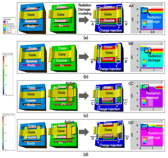
Figure 4.
Radiation damage models when radiation-induced interface charges were injected into (a) the standard structure; (b) the extended gate poly structure; (c) the structure to which the p-active and p+ doping regions are added; and (d) the combined structure of (b,c).
In the case of Model (c), however, the addition of the p-active and p+ doping regions allowed a gap to be formed between the isolation oxide films and the n+ region. Therefore, even though charges were trapped in the oxide films, the intrinsic electrical characteristics of the structure remained the same as they were before radiation-induced damage. The radiation tolerance properties of Model (c) were confirmed through M&S, but not entirely. The current semiconductor manufacturing process involves a silicide process to reduce the contact resistance of the electrodes. In the case of Model (c), the boundary between the p+ and n+ regions is not clear, and thus there is a risk of short-circuiting through the silicide layers. This may lead to the device malfunction. This risk will be examined in the next chapter with a device that was built and then subjected to measurements.
The drain current was simulated with respect to the gate voltage while increasing the degree of radiation-induced damage using the (a), (b), (c), and (d) models described in Figure 4. The results are shown in Figure 5. When Model (a) (standard structure) was applied, an unexpected channel distribution was induced by radiation at the isolation oxide film-silicon interfaces, thereby causing the formation of leakage current paths. As a result, the leakage current continued to increase as the concentration of injected charges increased, even when the gate voltage was lower than the threshold voltage. This meant that performance degradation occurred. In the case of Model (b), even though the gate poly was added, the isolation oxide films, which were the most prone to damage, were still in contact with the silicon n+ region. Thus, leakage currents were induced by radiation, thereby causing damage to the device, similar to that observed in Model (a). Model (e)’s radiation damage simulation results were also predictable because the model shared the same cross-sectional view as Model (b).
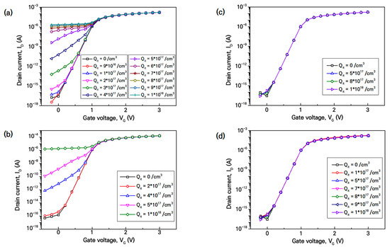
Figure 5.
Simulation results of the drain current with respect to the gate voltage varying depending on the concentration of injected interface charges in radiation damage models of (a) the standard structure; (b) the extended gate poly structure; (c) the structure to which the p-active and p+ doping regions are added; and (d) the combined structure of (b,c).
In the case of Model (d), the gate poly of Model (b) was applied to improve the limitations of Model (c). As shown in the simulation results, this structure provided radiation tolerance, and, at the same time, the applied gate poly allowed the p+ region to be separated from the n+ region.
2.4. Radiation Exposure Tests
Pattern-specific damage characteristics of the n-MOSFETs were predicted in advance by the radiation effect M&S analyses. Each layout was then actually designed, reflecting the conditions of the actual 0.18-um CMOS process, and test chips were fabricated accordingly [27,28]. Radiation tests were conducted at the high-level gamma-ray irradiation facility of the Advanced Radiation Technology Institute in Jeongeup, Korea. Cobalt-60 was used as the radiation source, and the dose rate was set to 1Mrad(Si)/h. The total cumulative radiation dose was 2Mrad(Si). The leakage current of the n-MOSFET was measured real-time while increasing the radiation dose. The applied test conditions are summarized in Table 1. The tests were conducted mutatis mutandis in accordance with the test procedures provided in the US Pentagon’s MIL-STD-883H 1019.8 [29].

Table 1.
Radiation test conditions for semiconductor devices.
Figure 6 shows changes in the leakage current with respect to the cumulative radiation dose. In n-MOSFETs (a), (b), and (e), damage patterns similar to the M&S results were observed, i.e., the leakage current increased with increasing radiation doses, and it started to saturate when the cumulative radiation dose reached about 1Mrad. The radiation tolerance characteristics of Model (c) were already examined through the M&S analysis. In practice, however, n-MOSFET (c) was found to malfunction before being subjected to the radiation exposure test, and this was attributed to a short circuit occurring during the silicide process. Based on the M&S results and the actual measurement results, it was confirmed that RH n-MOSFET structure (d) functioned properly, and its radiation tolerance characteristics were determined.
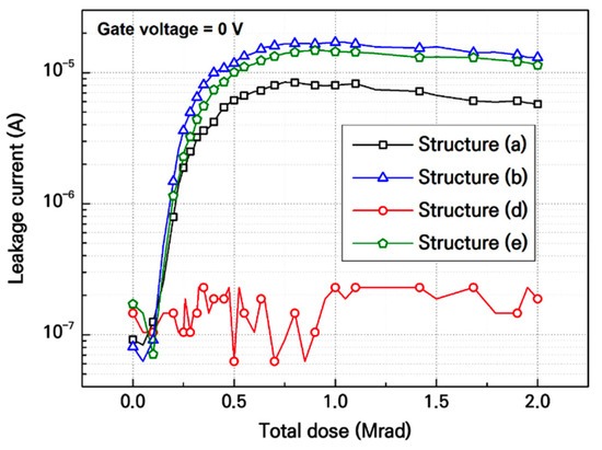
Figure 6.
Leakage current with respect to the cumulative radiation dose for each modified n-MOSFET layout structure.
3. Optimization of Radiation-Hardened n-MOSFET Design
3.1. Design of Radiation-Hardened Variable-Gate n-MOSFET
The performance of RH n-MOSFET (d) was previously verified through the radiation damage M&S analysis, and the actual radiation exposure tests. An RH variable-gate (V-gate) n-MOSFET was proposed and designed by improving the features of the RH n-MOSFET (d). The layout structure of the RH V-gate n-MOSFET included an RH variable layer set on both sides perpendicular to the gate of the standard structure (a). This RH layer set was composed of the poly gate, p+, and P-active layers, and its basic configuration is shown in Figure 7. The poly gate was located within the range where it could be in contact with the existing gate. The p+ layer was formed in the added poly gate on the other side of the existing gate so that it could meet the edge part of the added poly gate, or part of it could be included in the poly gate.
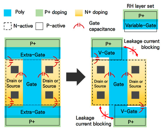
Figure 7.
Structural diagram of the improved radiation-hardened (RH) variable-gate n-MOSFET.
Unlike RH n-MOSFET (d) with a completely shut structure, the RH V-gate n-MOSFET included an RH variable layer set on both sides perpendicular to the existing gate, which allowed only part of the sources or drains to be shut down. In this way, the area where the gate meets the drains or sources could be minimized, and this made it possible to reduce the gate capacitance. The increase in radiation-induced leakage current in the MOSFET and an increase in its capacitance due to structural modifications all result in the same consequence, i.e., a reduction in the operating speed of the device. In this respect, the RH V-gate structure was designed to reduce leakage current-induced damage compared to the existing RH (d) structure.
Additionally, this modified structure was more advantageous than the existing RH structure in that the area could be reduced. As shown in Figure 8, this structure allows the RH layer set to locate in a variable way on both sides, and thus the saved area can be used as connecting paths for sources or drains. To sum up, this RH VG n-MOSFET provides various structural benefits in the RH circuit design by not only minimizing degradation in speed and area but also allowing the electrodes of each device to be connected in a more efficient manner. In addition, the RH layer set can be applied flexibly. This advantage can be applied by changing the size of the RH layer set even if the channel size (width/length) of the device changes. Therefore, irrespective of the device size, radiation damage can be prevented.
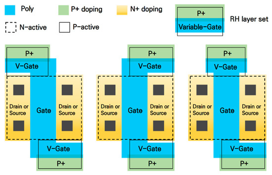
Figure 8.
Structural diagram of the RH variable-gate n-MOSFET application.
Figure 9 shows a cross-sectional view of the RH V-gate n-MOSFET. Here, the RH layer set blocks part of the leakage current paths in the isolation oxide films. As part of the RH layer set, the poly gate not only acts as a silicide blocking layer against short circuits in the p+ and n+ regions but also isolates the isolation oxides from the sources or drains. The P-active layer was formed to be in contact with the edge part of the N-active layer so that the formation of isolation oxides between the active regions could be prevented. In the standard n-MOSFET, the radiation-induced leakage current path is formed by meeting the n+ regions of the source and drain along the boundary between the insulation oxide and the N-active region. Since the proposed RH VG structure partially applies the RH layer set between the drain and the source, the P-active region of the RH layer set partially separates the insulation oxide film from the existing n+ region and blocks the generation of the leakage current path.
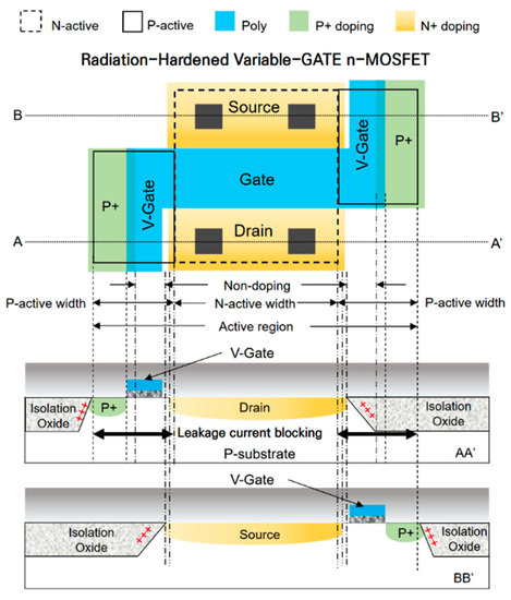
Figure 9.
Cross-sectional view of the RH V-gate n-MOSFET.
The p+ layer serves to prevent the holes trapped in the most outer isolation oxide layer from affecting the n+ region. The RH layer set composed of these layers is capable of selectively blocking the connection between the isolation oxide films and the sources and drains. Therefore, when applied to circuit design, this system ensures efficient area management.
3.2. M&S of the Radiation Effect on RH Variable Gate n-MOSFET
A radiation damage model was designed to assess the radiation tolerance performance of the RH VG n-MOSFET by applying the interface charge injection technique. The basic dimensions of the 3D characteristic model before the injection were as follows: 1 um (length), 2 um (width), 10 nm (gate oxide thickness), and 3 um (body thickness). The doping concentrations for each region were set as follows: 8 × 10¹⁶/cm3 (body), 1 × 10¹⁸/cm3 (channel), and 1 × 10²⁰/cm3 (sources and drains). The gate size and p+ doping concentration of the RH layer set were 0.4 um/1.5 um (width/length) and 1 × 10¹⁹/cm3, respectively. Figure 10 shows the RH VG n-MOSFET characteristic model, and Table 2 summarizes its geometry and doping profiles [30].
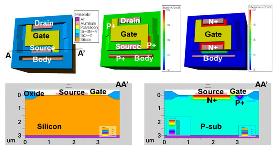
Figure 10.
3D characteristic model for the RH V-gate n-MOSFET and its cross-sectional view.

Table 2.
Geometry and doping profiles of the RH V-gate n-MOSFET.
The radiation-induced charge injection model for radiation damage assessment was employed to perform the radiation tolerance performance M&S. As shown in Figure 11, an increase in the cumulative radiation dose was simulated by controlling the concentration of the charges trapped at the silicon interfaces, and IDrain-VGate characteristic curves were plotted with respect to the increasing charge concentration to analyze the electrical properties of the n-MOSFET and further verify its radiation tolerance. The simulation conditions were Vp-sub = 0 V, Vdrain = 0.1 V, Vsource = 0 V, and Vgate = −0.4~3 V. The concentration of the silicon interface-trapped charges was increased to up to 5 × 10¹⁸/cm3, and, in the meantime, the electrical characteristics of the device were simulated with respect to the varying charge concentration. The results are shown in Figure 12.
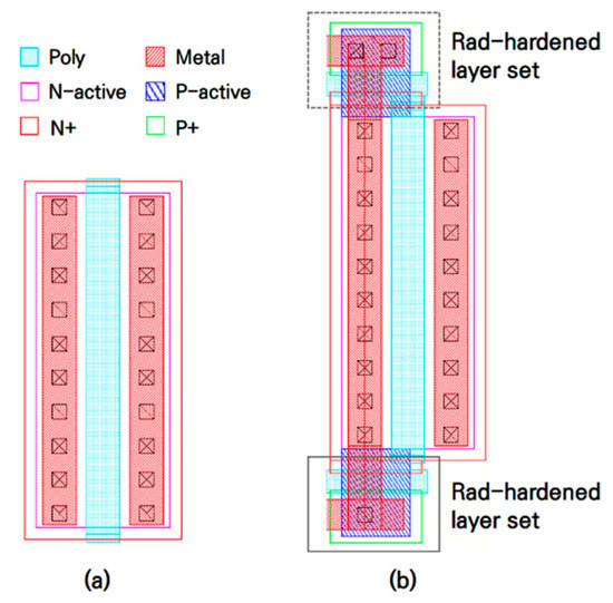
Figure 11.
3D radiation damage model for RH V-gate n-MOSFET and its cross-sectional view.
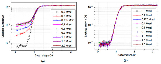
Figure 12.
I-V characteristic simulation results obtained using the RH V-gate n-MOSFET radiation damage model with respect to the injected charge concentration.
It was found that the RH V-gate n-MOSFET was able to maintain its intrinsic electrical properties as the concentration of radiation-induced interface charges was increased to 5 × 10¹⁸/cm3. These results confirm that the RH V-gate n-MOSFET has a highly efficient, compact structure that inherits the radiation-tolerance characteristics and advantages of the existing (d) structure because all the unnecessary elements have been removed and the parts that may have caused the performance degradation of the device have been modified.
3.3. Radiation Exposure Tests and Results Analysis on RH Variable Gate n-MOSFET
The performance of the optimized RH n-MOSFET structure was verified through the M&S-based radiation tolerance assessment. To experimentally verify its performance, chips were actually fabricated in a commercial 0.18-um CMOS process. Figure 13 shows the optimized drawings to which the layout modifications were applied. Standard n-MOSFET was also fabricated as a control group.

Figure 13.
n-MOSFET layout drawings in the 0.18-um CMOS process (a) standard and (b) RH V-gate n-MOSFET.
Radiation tests were conducted on the optimized structure under the same conditions as in the pattern-specific n-MOSFET tests described earlier in Section 2.4, i.e., by increasing the cumulative radiation dose up to 2 Mrad.
As shown in Figure 14, the drain currents of both the standard structure and the RH V-gate n-MOSFET structure were experimentally measured with respect to the gate voltage. While the gate voltage was lower than the threshold voltage, i.e., the device remained turned off, a leakage current was measured with increasing cumulative radiation doses. In the case of the standard structure, even though it remained turned off, the leakage current rapidly increased to about 10 uA until the cumulative radiation dose reached 1Mard, and then it started to saturate. This indicates that, when exposed to radiation environments, standard n-MOSFET-based ICs may experience malfunctions or data errors as the cumulative radiation dose increases. In contrast, the leakage current in the RH V-gate n-MOSFET structure was kept below nA levels regardless of the cumulative radiation dose. These results confirmed the improved radiation tolerance performance of the modified structure, and the predicted results obtained with the M&S techniques were experimentally verified to be valid.
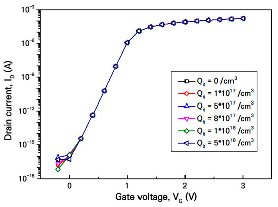
Figure 14.
Leakage current measurements with respect to increasing cumulative doses (a) standard and (b) RH V-gate n-MOSFET.
4. Conclusions
In the present study, a radiation-tolerant MOSFET structure was optimized in an attempt to ensure electronic devices will maintain their original performance when exposed to radiation environments. M&S techniques were employed to conduct a radiation effect assessment and allowed us to attempt to modify the layout structure using various patterns as desired. This approach helped us to determine reliable estimates of the radiation-tolerance characteristics of the designed structures before starting the actual manufacturing of the semiconductor chips, thereby minimizing research and development costs and time. We compared and analyzed the damage and tolerance characteristics of n-MOSFETs through the radiation injection M&S and proposed a radiation-hardened variable-gate n-MOSFET. The proposed RH VG n-MOSFET was designed and fabricated in the 0.18-um CMOS process, and radiation exposure tests were performed together with the standard n-MOSFET. As a result of the radiation measurement, the radiation damage occurred in the standard n-MOSFET, but the proposed RH VG structure was confirmed to be radiation-tolerant up to a total cumulative dose of 2 Mrad.
Finally, an optimized RH VG n-MOSFET structure was developed and subjected to M&S-based verification, actual fabrication, and experimental verification through radiation exposure tests. The major findings of the present study are expected to significantly contribute to implementation of the radiation-tolerant design in a wide range of applications, from electronic circuits to systems.
Author Contributions
Conceptualization, M.L. and N.L.; methodology, M.L. and S.C.; software, M.L. and Y.H; validation, S.C., M.L. and N.L.; investigation, J.K.; data curation, Y.H. and J.K.; writing—original draft preparation, M.L. and N.L.; writing—review and editing, S.C. and M.L.; visualization, Y.H.; supervision, S.C.; project administration, N.L. All authors have read and agreed to the published version of the manuscript.
Funding
This research was supported by the National Research Foundation of Korea (NRF) funded by the Korea government (MSIT: Ministry of Science and ICT) (No. 2018M2A8A5083266). This work was supported by the Nuclear R&D program of the Ministry of Science and ICT (523420-21).
Conflicts of Interest
The authors declare no conflict of interest.
References
- Holmes-Siedle, A.; Adams, L. Handbook of Radiation Effects, 2nd ed.; Oxford Univ. Press: Oxford, UK, 2002. [Google Scholar]
- Oldham, T.R. Analysis of damage in MOS devices in several radiation environments. IEEE Trans. Nucl. Sci. 1984, 31, 1236–1241. [Google Scholar] [CrossRef]
- Edward, C.E. Radiation effects research in the 60’s. IEEE Trans. Nucl. Sci. 1994, 41, 2648–2659. [Google Scholar]
- Nidhin, T.S.; Bhattacharyya, A.; Behera, R.P.; Jayanthi, T.; Velusamy, K. Understanding radiation effects in SRAM-based field programmable gate arrays for implementing instrumentation and control systems of nuclear power plants. Nucl. Eng. Technol. 2017, 49, 1589–1599. [Google Scholar] [CrossRef]
- Srour, J.R.; McGarrity, J.M. Radiation Effects on Microelctronics in Space. Proc. IEEE 1988, 76, 1443–1469. [Google Scholar] [CrossRef]
- Sujatha, R.; Abdul, R.K.; Ravindra, M.; Damle, R. Study of effect fo gamma radiation on MOSFET for space applications. Indian J. Pure Appl. Phys. 2018, 56, 587–590. [Google Scholar]
- Messenger, G.C.; Ash, M.S. The Effects of Radiation on Electronic Systems; Springer Press: Van Nostrand Reinhold, NY, USA, 1992. [Google Scholar]
- Stephen, G.; van Nicolaas, V.; Steven, V.; Wesley, M. Integrated Circuit Design for Radiation Environments, 1st ed.; Wiley/John Wiley & Sons: Hoboken, NJ, USA, 2019. [Google Scholar]
- Lacoe, R.C.; Osborn, J.V.; Mayer, D.C.; Brown, S.; Koga, R. Application of hardness-by-design methodology to radiation-tolerant ASIC technologies. IEEE Trans. Nucl. Sci. 2000, 47, 2334–2341. [Google Scholar] [CrossRef]
- Deval, Y.; Lapuyade, H.; Rivet, F. Design of CMOS integrated circuits for radiation hardening and its application to space electronics. In Proceedings of the 2019 IEEE 13th International Conference on ASIC (ASICON), Chongqing, China, 29 October–1 November 2019. [Google Scholar]
- Schwank, J.R.; Shaneyfelt, M.R.; Draper, B.L.; Dodd, P.E. BUSFET-a radiation-hardened SOI transistor. IEEE Trans. Nucl. Sci. 1999, 46, 1809–1816. [Google Scholar] [CrossRef]
- Chen, L.; Gingrich, D.M. Study of N- Channel MOSFETs with an Enclosed-Gate Layout in a 0.18 um CMOS technology. IEEE Trans. Nucl. Sci. 2005, 52, 861–867. [Google Scholar] [CrossRef]
- Lee, M.S.; Lee, H.C. Dummy Gate- Assisted n-MOSFET Layout for a Radiation-Tolerant Integrated Circuit. IEEE Trans. Nucl. Sci. 2013, 60, 3084–3091. [Google Scholar] [CrossRef]
- Bezhenova, V.; Michalowska-Forsyth, A. Aspect ratio of radiation-hardened MOS transistors. Elektrotechnik Inf. 2018, 135, 61–68. [Google Scholar] [CrossRef]
- Luís Eduardo, S., Jr.; Odair Lellis, G.; Rafael, G.V.; da Antonio Carlos, C.T.; Saulo, F.; Salvador Pinillos, G. Minimizing the TID effects due to gamma rays by using diamond layout for MOSFETs. J. Mater. Sci. Mater. Electron. 2019, 30, 4339–4351. [Google Scholar]
- Chatzikyriakou, E.; Morgan, K.; Groot, C.H.K. Total ionizing dose hardened and mitigation strategies in deep submicrometer CMOS and beyond. IEEE Trans. Electron Devices 2018, 65, 808–819. [Google Scholar] [CrossRef]
- Louise, L.; Alexandre, Q.; Evelyne, D.; Fortunato, D. Effects of Ionizing Radiation in Semiconductor Device: Simulation with Geant4. Mardi Chercheurs. 2019. Available online: https://www.researchgate.net/publication/335882715_Effects_of_ionizing_radiation_in_semiconductor_devices_simulation_with_Geant4 (accessed on 21 February 2021).
- Giacomini, R.; Martino, J.A. Modeling Silicon on Insulator MOS Transistors with Nonrectangular-Gate Layouts. J. Electrochem. Soc. 2006, 153, G218–G222. [Google Scholar] [CrossRef]
- Barnaby, H.J. Total-Ionizing-Dose Effects in Modern CMOS Technologies. IEEE Trans. Nucl. Sci. 2006, 53, 3103–3120. [Google Scholar] [CrossRef]
- Fleetwood, D.M.; Winokur, P.S.; Reber, R.A.; Meisenheimer, T.L.; Schwank, J.R.; Shaneyfelt, M.R.; Riewe, L.C. Effects of oxide traps, interface traps, and ‘border traps’ on metal-oxide-semiconductor devices. J. Appl. Phys. 1993, 73, 5058–5074. [Google Scholar] [CrossRef]
- Oldham, T.R.; Mclean, F.B. Total Ionizing Dose Effects in MOS Oxides and Devices. IEEE Trans. Nucl. Sci. 2003, 50, 483–496. [Google Scholar] [CrossRef]
- Sang-hun, J.; Nam-ho, L.; Seong-ik, C. Analysis of Radiation Effects in CMOS 0.18um Process Unit Devices. Trans. Korean Inst. Electr. Eng. 2017, 66, 540–544. [Google Scholar]
- Benedetto, J.M.; Boesch, H.E., Jr.; McLean, F.B.; Mize, J.P. Hole removal in thin gate MOSFET’s by tunneling. IEEE Trans. Nucl. Sci. 1985, 32, 3916. [Google Scholar] [CrossRef]
- Saks, N.; Ancona, M.; Modolo, J. Generation of interface states by ionizing radiation in very thin MOS oxides. IEEE Trans. Nucl. Sci. 1986, 33, 1185–1190. [Google Scholar] [CrossRef]
- Lee, M.; Lee, N.; Kim, J.; Cho, S. New Radiation-Hardened Design of a CMOS Instrumentation Amplifier and its Tolerant Characteristic Analysis. Electronics 2020, 9, 388. [Google Scholar] [CrossRef]
- Esqueda, I.S.; Barnaby, H.J. Modeling the Non-Uniform Distribution of Radiation-Induced Interface Traps. IEEE Trans. Nucl. Sci. 2012, 59, 723–727. [Google Scholar] [CrossRef]
- Jacob Baker, R. CMOS: Circuit Design, Layout, and Simulation, 3rd ed.; John Wiley and Sons Ltd.: Hoboken, NJ, USA, 2010. [Google Scholar]
- Razavi, B. Design of Analog CMOS Integrated Circuits; FBW New Edition; McGraw-Hill: Boston, CA, USA, 2000. [Google Scholar]
- Ionizing Radiation (Total Dose) Test Procedure; MIL-STD-883H 1019.8; U.S. Department of Defense: Washington, DC, USA, 2010. Available online: http://everyspec.com/MIL-STD/MIL-STD-0800-0899/MIL-STD-883H_21092/ (accessed on 5 December 2020).
- Semenov, O.; Sarbishaei, H.; Axelrad, V.; Sachdev, M. The Impact of CMOS technology scaling on MOSFETs second breakdown: Evaluation of ESD robustness. Microelectron. Reliab. 2004, 44, 1817–1822. [Google Scholar]
Publisher’s Note: MDPI stays neutral with regard to jurisdictional claims in published maps and institutional affiliations. |
© 2021 by the authors. Licensee MDPI, Basel, Switzerland. This article is an open access article distributed under the terms and conditions of the Creative Commons Attribution (CC BY) license (https://creativecommons.org/licenses/by/4.0/).