PD-Type Iterative Learning Control with Adaptive Learning Gains for High-Performance Load Torque Tracking of Electric Dynamic Load Simulator


Abstract
1. Introduction
2. Dynamic Model of Electric Dynamic Load Simulator
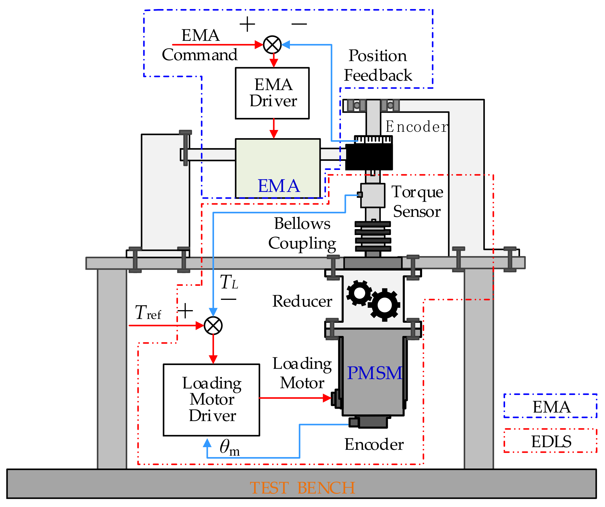
2.1. Subsection System Architecture of Electric Dynamic Load Simulator
2.2. Mathematical Model of Electric Dynamic Load Simulator
3. Controller Design for Electric Dynamic Load Simulator
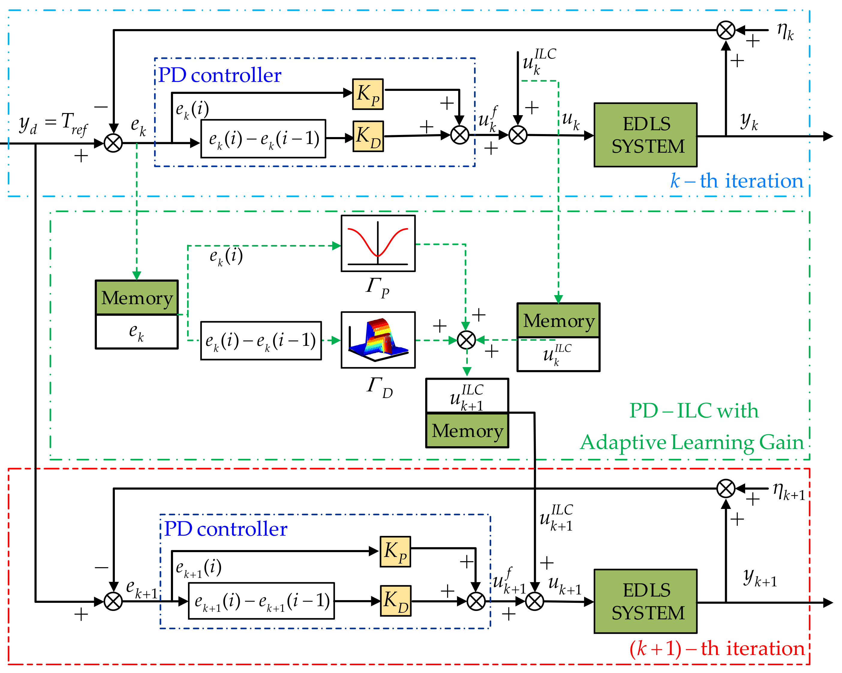
3.1. The Framework of PD-Type Iterative Learning Control Law with Adaptive Learning Gains
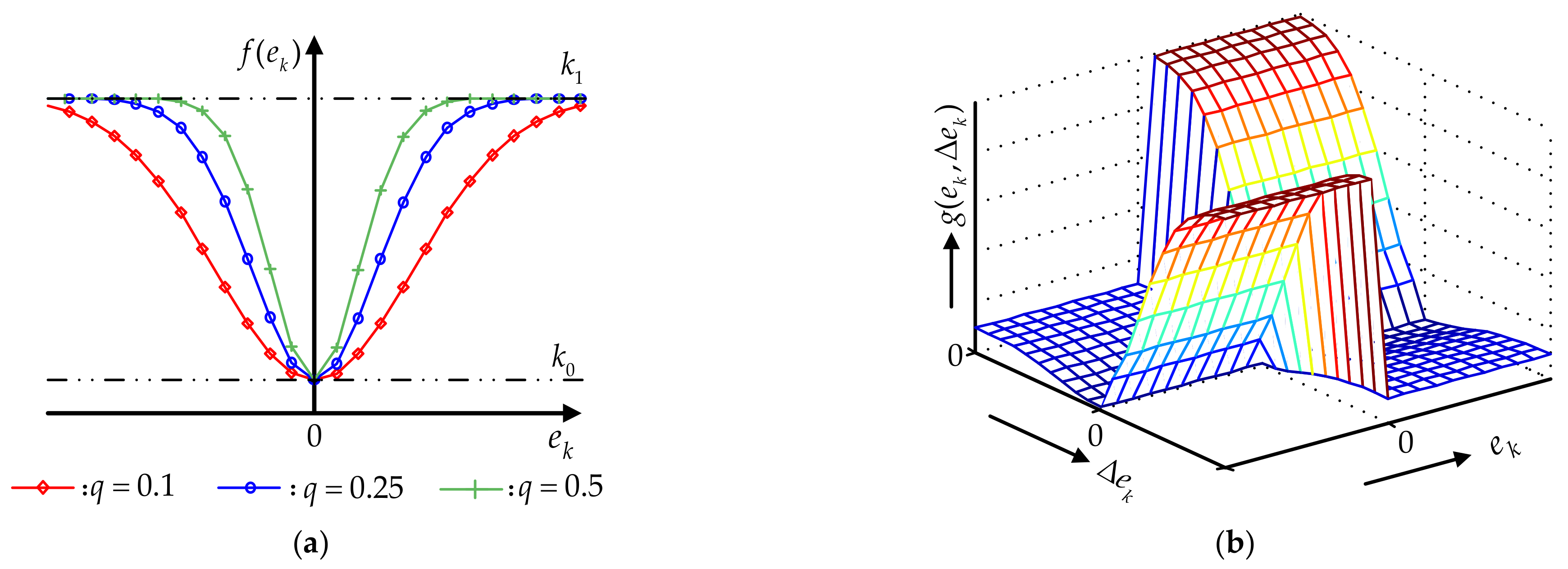
- : The proportional control gain can reflect the error signal of the control system proportionally. When the error is generated, the controller will immediately exert control action to reduce the error.
- : The derivative term is used to reflect the change rate of the error signal, which can introduce an effective early correction signal into the system before the error signal becomes too big, so as to accelerate the response speed of the system and reduce the adjustment time.
3.2. The PD-Type Iterative Learning Control Adaptive with Learning Gains Controller Design
3.3. Convergence Analysis
- The ideal control input set can make the system state and system output track the ideal states and the desired output , respectively;
- The initial state error of each iteration satisfies , and satisfies with ;
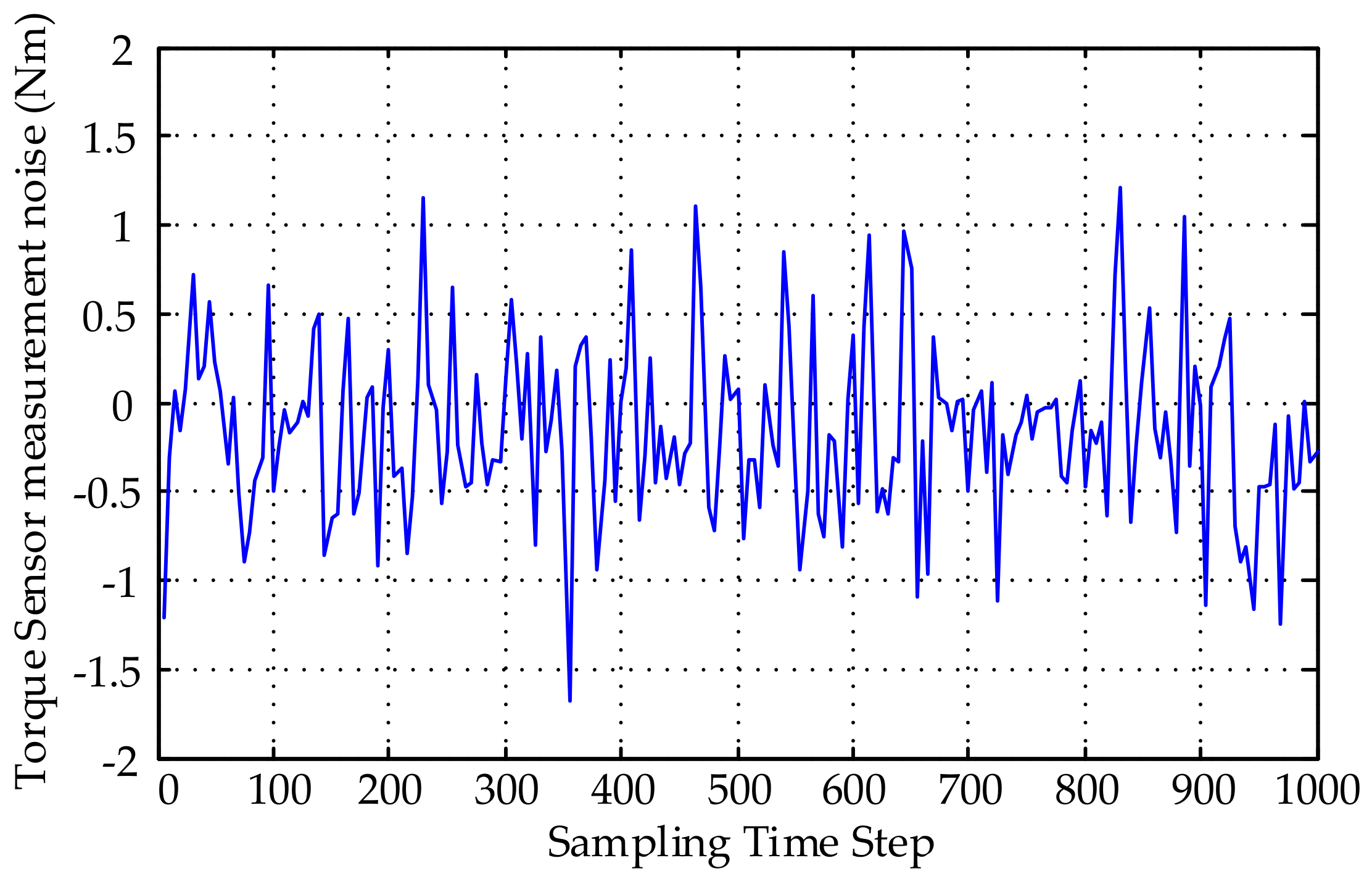
- The periodic disturbance and the output measurement noise are bounded as follows: and ; ; and are known positive constants;
- The periodic disturbance satisfies: and , ;
4. Experimental Evaluation
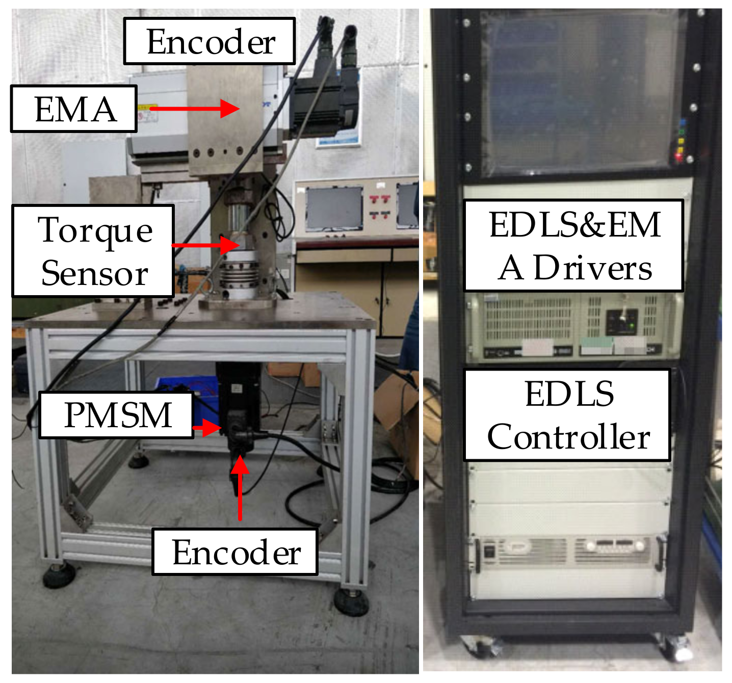
4.1. Experimental Setup
4.2. Experimental Results
- (1)
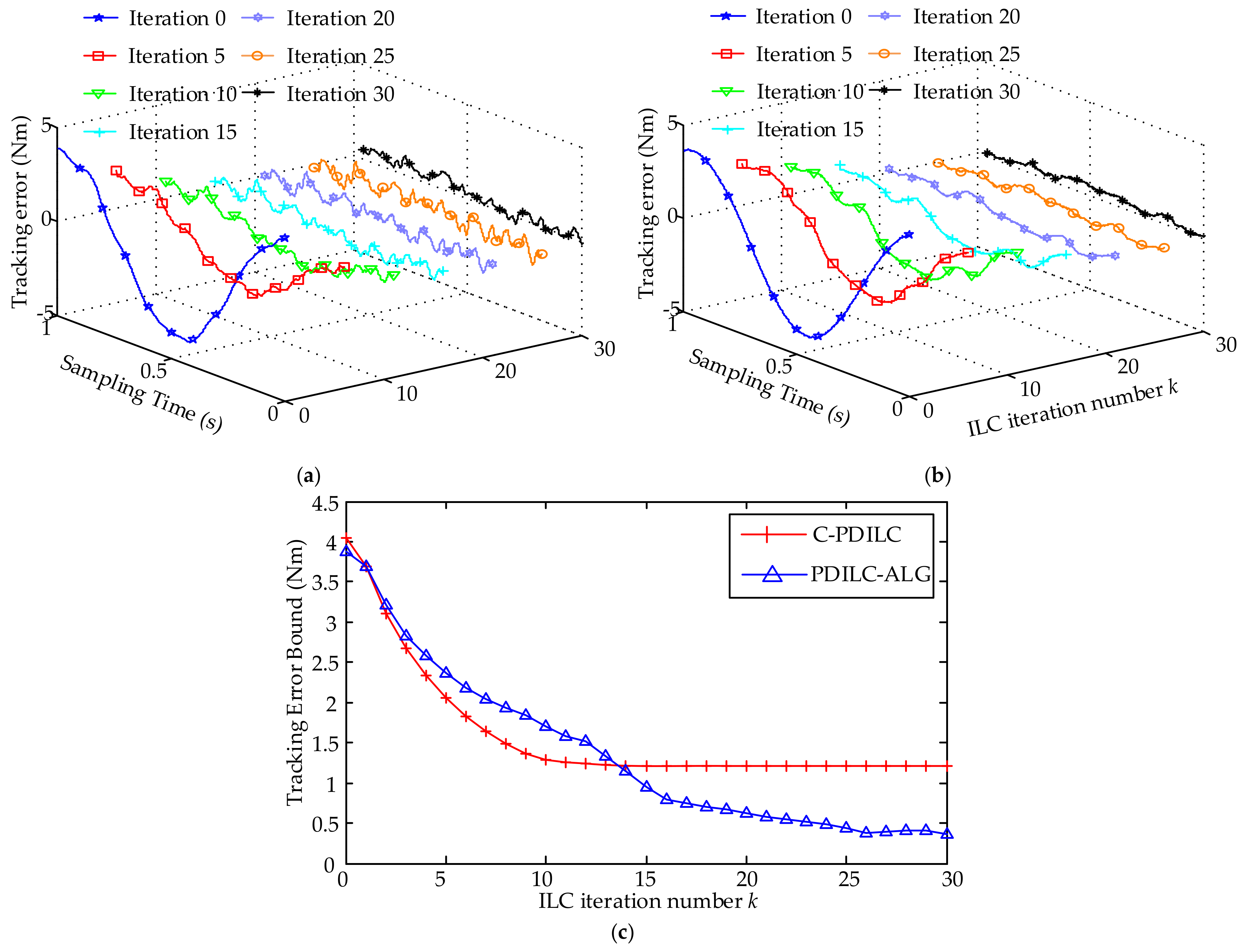
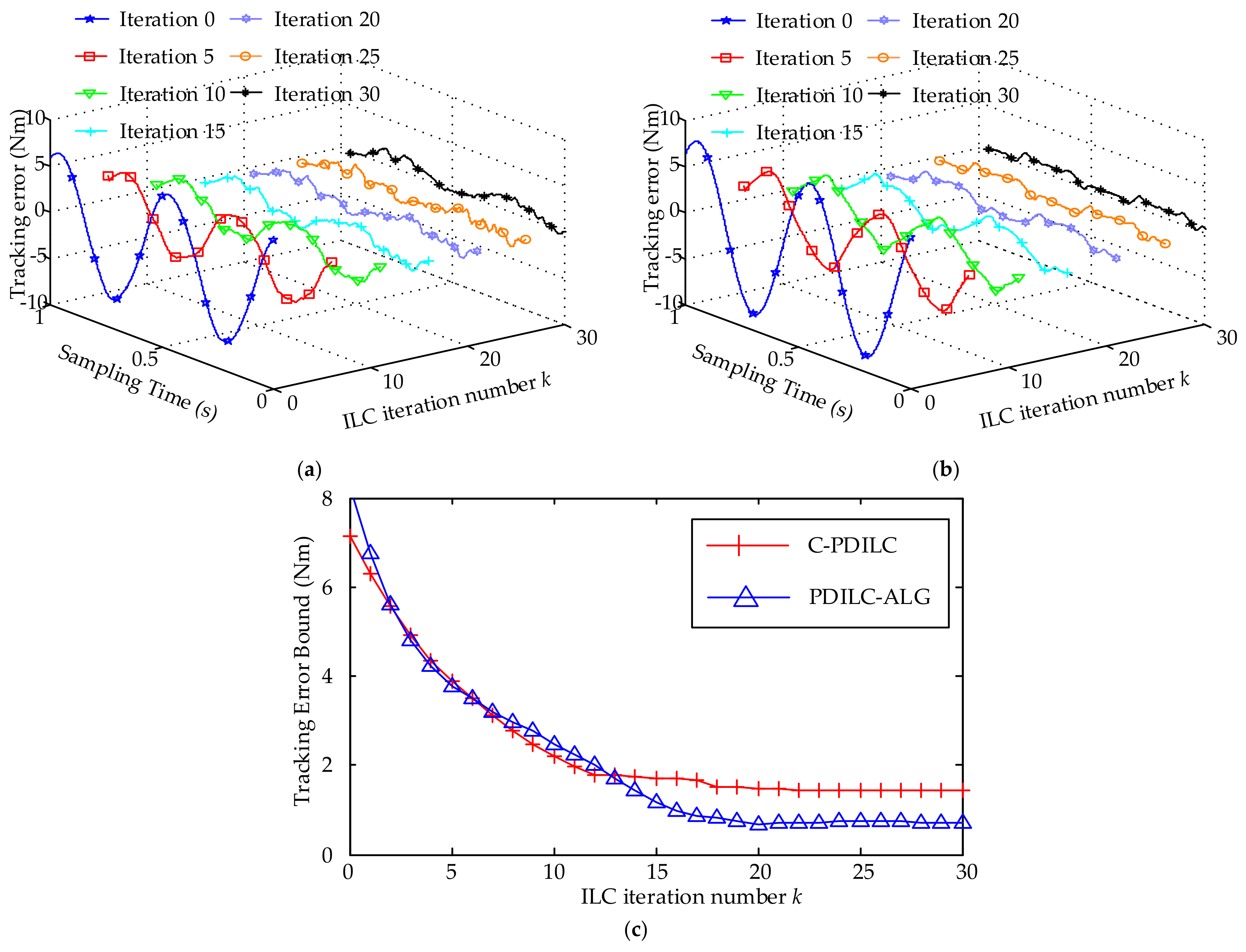
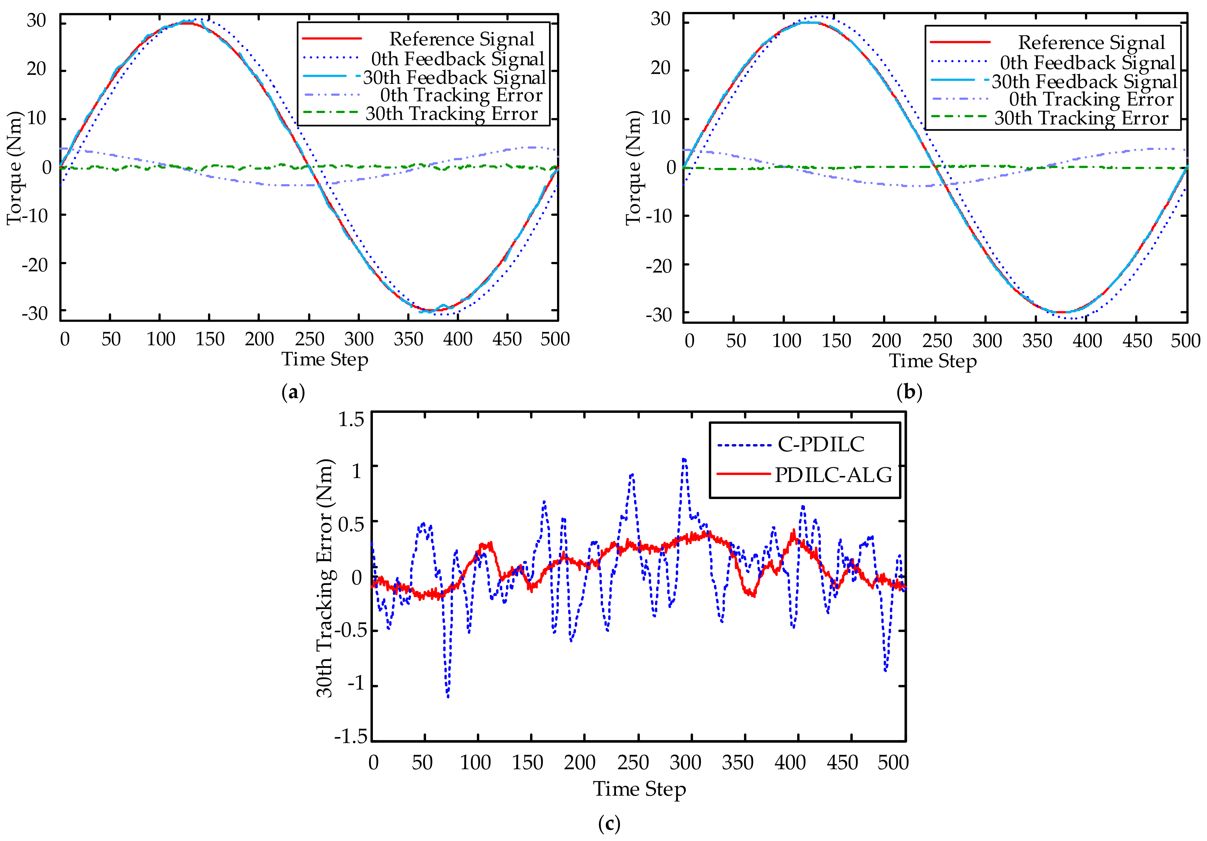
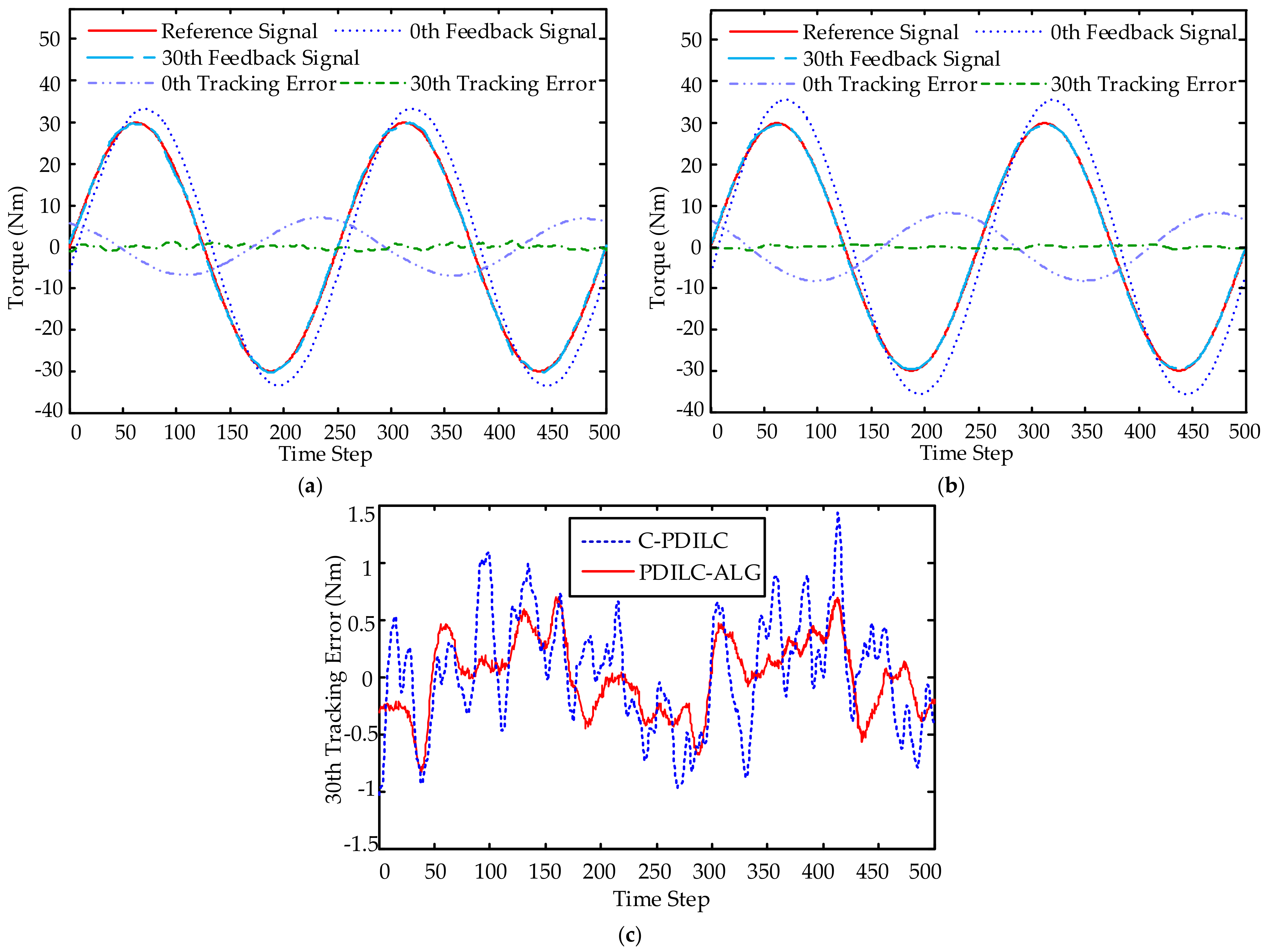
- Conventional PD-type ILC (C-PDILC): this is a combination of a standard PD feedback controller and a conventional PD-type ILC. The conventional PD-type ILC with fixed learning gains can be seen as a special case of the proposed method in this paper, for all . and are restricted to be constant scalars. To satisfy the condition of Equation (38), the control gains of PD feedback controller are chosen as and , and the PD-type learning gains are chosen as and . For all frequencies up to the Nyquist frequency, one can get:
- (2)
- PD-type ILC with adaptive learning gains (PDILC-ALG): this is the proposed method in this paper. In order to satisfy the condition of Equation (38), the parameters of adaptive learning gains are chosen as , , , , , and . The proportional gain of the feedback controller is the same as the conventional PD-type ILC; i.e., and . Then, for all frequencies up to the Nyquist frequency and all , one can get:
5. Conclusions
Author Contributions
Funding
Conflicts of Interest
Abbreviations
| Notation | Physical Significance |
| electromagnetic torque | |
| the equivalent gain of the PMSM driver | |
| the control input | |
| loading motor anglular position | |
| loading motor anglular speed | |
| total inertia | |
| damping coefficient | |
| the simulated load torque of EMA under test | |
| the reduction ratio of the reducer | |
| the lumped disturbance torque | |
| the stiffness coefficient of the torque sensor | |
| EMA anglular position | |
| EMA anglular speed | |
| the random measurement noise | |
| system states | |
| state matrices | |
| the sample period | |
| the identify matrix of appropriate dimension | |
| state space matrices | |
| the bounded periodical load torque trajectory | |
| the present iteration | |
| the desired periodical loading torque trajectory | |
| the tracking error | |
| the system practical output | |
| the output of PD feedback controller | |
| the proportional gain | |
| the derivative gain | |
| the output of PD-type ILC controller | |
| the proportional learning gain | |
| the derivative learning gain | |
| the first difference of tracking error | |
| the positive constant gain | |
| the positive constant gain | |
| the upper bound of nonlinear function | |
| the lower bound of nonlinear function | |
| the positive constant | |
| the positive constant | |
| the positive constant | |
| the positive constant | |
| z-transform | |
| the Nyquist frequency |
References
- Zhang, M.; Li, C.; Wu, X.; Zhu, Y. All-Electric Aircraft Nose Wheel Steering System with Two Worm Gears. Trans. Nanjing Univ. Aero. Astro. 2018, 35, 170–180. [Google Scholar] [CrossRef]
- Barzkar, A.; Ghassemi, M. Electric Power Systems in More and All Electric Aircraft: A Review. IEEE Access 2020, 8, 169314–169332. [Google Scholar] [CrossRef]
- Qiao, G.; Liu, G.; Shi, Z.H.; Wang, Y.W.; Ma, S.J.; Lim, T.C. A review of electromechanical actuators for More/All Electric aircraft systems. Proc. Inst. Mech. Eng. Part C J. Mech. Eng. Sci. 2018, 232, 4128–4151. [Google Scholar] [CrossRef]
- Gu, N.H.; Yang, B. Semi-fuzzy CMAC and PD hybrid controller with compressed memory and semi-regularisation for electric load simulator. IET Control. Theory Appl. 2019, 13, 3065–3074. [Google Scholar] [CrossRef]
- Li, C.C.; Li, Y.F.; Wang, G.L. H∞ output tracking control of Electric-motor-driven aerodynamic Load Simulator with external active motion disturbance and nonlinearity. Aerosp. Sci. Technol. 2018, 82, 334–349. [Google Scholar] [CrossRef]
- Wang, L.S.; Wang, M.Y.; Guo, B.; Wang, Z.; Wang, D.; Li, Y. A Loading Control Strategy for Electric Load Simulators Based on Proportional Resonant Control. IEEE Trans. Ind. Electron. 2018, 65, 4608–4618. [Google Scholar] [CrossRef]
- Wang, X.J.; Wang, S.P.; Yao, B. Adaptive Robust Torque Control of Electric Load Simulator with Strong Position Coupling Disturbance. Int. J. Control Autom. Syst. 2013, 11, 325–332. [Google Scholar] [CrossRef]
- Wang, L.S.; Wang, M.Y.; Guo, B.; Zhe, W.; Li, Y.L. Analysis and Design of a Speed Controller for Electric Load Simulators. IEEE Trans. Ind. Electron. 2016, 63, 7413–7422. [Google Scholar] [CrossRef]
- Mare, J.C. Dynamic loading systems for ground testing of high speed aerospace actuators. Aircr. Eng. Aerosp. Technol. 2006, 78, 275–282. [Google Scholar] [CrossRef]
- Liu, X.; Yang, R.F.; Jia, J. The Control System of Electric Load Simulator Based on Neural Network. In Advances in Future Computer and Control Systems; David, J., Sally, L., Eds.; Springer: Berlin/Heidelberg, Germany, 2012; pp. 681–687. [Google Scholar] [CrossRef]
- Abdolah, S.; Zahra, K. Robust fault-tolerant controller design for aerodynamic load simulator. Aerosp. Sci. Technol. 2018, 78, 332–341. [Google Scholar] [CrossRef]
- Wang, S.K.; Wang, J.Z.; Zhao, J.B. A case study of electro-hydraulic loading and testing technology for composite insulators based on iterative learning control. P I MECH ENG I-J SYS 2013, 227, 498–506. [Google Scholar] [CrossRef]
- Jiao, Z.X.; Li, C.G.; Ren, Z.T. Extraneous torque and compensation control on the electric load simulator. In Proceedings of the Fifth International Symposium on Instrumentation and Control Technology, Beijing, China, 24–27 October 2003. [Google Scholar] [CrossRef]
- Yang, B.; Bao, R.; Han, H.T. Robust Hybrid Control Based on PD and Novel CMAC With Improved Architecture and Learning Scheme for Electric Load Simulator. IEEE Trans. Ind. Electron. 2014, 61, 5271–5279. [Google Scholar] [CrossRef]
- Arimoto, S.; Kawamura, S.; Miyazaki, F. Bettering operation of Robots by learning. J. Robot. Syst. 1984, 1, 123–140. [Google Scholar] [CrossRef]
- Bristow, D.A.; Tharayil, M.; Alleyne, A.G. A survey of iterative learning control. IEEE Control Syst. 2006, 26, 96–114. [Google Scholar] [CrossRef]
- Wang, M.Y.; Guo, B.; Guan, Y.D.; Zhang, H. Design of electric dynamic load simulator based on recurrent neural networks. In Proceedings of the IEEE International Electric Machines and Drives Conference, 2003. IEMDC’03, Madison, WI, USA, 1–4 June 2003; pp. 207–210. [Google Scholar] [CrossRef]
- Wang, D.W.; Ye, Y.Q.; Zhang, B. Practical Iterative Learning Control with Frequency Domain Design and Sampled Data Implementation; Springer: Singapore, 2014; pp. 7–13. ISBN 978-981-4585-60-6. [Google Scholar]
- Puchta, E.D.P.; Siqueira, H.V.; Dos Santos Kaster, M. Optimization Tools Based on Metaheuristics for Performance Enhancement in a Gaussian Adaptive PID Controller. IEEE Trans. Cybern. 2019, 50, 1185–1194. [Google Scholar] [CrossRef] [PubMed]
- Zhong, L.N.; Rahman, M.F.; Hu, Y.W.; Lim, K.W. Analysis of direct torque control in permanent magnet synchronous motor drives. IEEE Trans. Power Electron. 1997, 12, 528–536. [Google Scholar] [CrossRef]
- Fei, Q.; Deng, Y.T.; Li, H.W.; Liu, J.; Shao, M. Speed Ripple Minimization of Permanent Magnet Synchronous Motor Based on Model Predictive and Iterative Learning Controls. IEEE Access 2019, 7, 31791–31800. [Google Scholar] [CrossRef]
- Owens, D.H. Iterative Learning Control—An Optimization Paradigm; Springer: London, UK, 2005; pp. 1–17. ISBN 978-1-4471-6772-3. [Google Scholar]
- Li, B.Q.; Lin, H.; Xing, H.L. Adaptive adjustment of iterative learning control gain matrix in Harsh noise environment. J. Syst. Eng. Electron. 2013, 24, 128–134. [Google Scholar] [CrossRef]
- Ghosh, J.; Paden, B. Pseudo-inverse based iterative learning control for plants with unmodelled dynamics. In Proceedings of the 2000 American Control Conference, ACC (IEEE Cat. No.00CH36334), Chicago, IL, USA, 28–30 June 2000; pp. 472–476. [Google Scholar] [CrossRef]
- Bu, X.H.; Hou, Z.S.; Yu, F.S.; Wang, F.Z. H∞ iterative learning controller design for a class of discrete-time systems with data dropouts. Int. J. Syst. Sci. 2014, 45, 1902–1912. [Google Scholar] [CrossRef]
- Liu, Q.; Tian, S.P.; Gu, P.P. P-type iterative learning control algorithm for a class of linear singular impulsive systems. J. Franklin Inst. 2018, 355, 3926–3937. [Google Scholar] [CrossRef]
- Wang, L.; Li, M.; Yang, H.Z. Robust PD-Type Iterative Learning Control of Discrete Linear Repetitive Processes in the Finite Frequency Domain. Mathematics 2020, 8, 1004. [Google Scholar] [CrossRef]
- Dos Santos, L.A.; Dos Santos Kaster, M.; Da Silva, S.A.O. Applying a nonlinear PID in a singlephase PLL control. In Proceedings of the 2012 IEEE International Conference on Power Electronics, Drives and Energy Systems (PEDES), Bengaluru, India, 16–19 December 2012; pp. 1–4. [Google Scholar] [CrossRef]
- Xu, J.X.; Panda, S.K.; Lee, T.H. Real-time Iterative Learning Control; Springer: London, UK, 2009; pp. 29–45. ISBN 978-1-84882-174-3. [Google Scholar]


| Rated Power | Rated Speed | Rated Torque | Rated Voltage |
|---|---|---|---|
| Parameter | Value | Unit |
|---|---|---|
| 0.955 | ||
| 0.000697 | ||
| 0.00018 | ||
| 35 | dimensionless | |
| 8500 |
| Strategy | |||
|---|---|---|---|
| 8th | 18th | 28th | |
| C-PDILC | |||
| PDILC-ALG | |||
| Strategy | |||
|---|---|---|---|
| 8th | 18th | 28th | |
| C-PDILC | |||
| PDILC-ALG | |||
| Strategy | Maximum Error | Minimum Error | |
|---|---|---|---|
| C-PDILC | |||
| PDILC-ALG |
| Strategy | Maximum Error | Minimum Error | |
|---|---|---|---|
| C-PDILC | |||
| PDILC-ALG |
Publisher’s Note: MDPI stays neutral with regard to jurisdictional claims in published maps and institutional affiliations. |
© 2021 by the authors. Licensee MDPI, Basel, Switzerland. This article is an open access article distributed under the terms and conditions of the Creative Commons Attribution (CC BY) license (http://creativecommons.org/licenses/by/4.0/).
Share and Cite
Dai, M.; Qi, R.; Zhao, Y.; Li, Y. PD-Type Iterative Learning Control with Adaptive Learning Gains for High-Performance Load Torque Tracking of Electric Dynamic Load Simulator. Electronics 2021, 10, 811. https://doi.org/10.3390/electronics10070811
Dai M, Qi R, Zhao Y, Li Y. PD-Type Iterative Learning Control with Adaptive Learning Gains for High-Performance Load Torque Tracking of Electric Dynamic Load Simulator. Electronics. 2021; 10(7):811. https://doi.org/10.3390/electronics10070811
Chicago/Turabian StyleDai, Mingguang, Rong Qi, Yiyun Zhao, and Yang Li. 2021. "PD-Type Iterative Learning Control with Adaptive Learning Gains for High-Performance Load Torque Tracking of Electric Dynamic Load Simulator" Electronics 10, no. 7: 811. https://doi.org/10.3390/electronics10070811
APA StyleDai, M., Qi, R., Zhao, Y., & Li, Y. (2021). PD-Type Iterative Learning Control with Adaptive Learning Gains for High-Performance Load Torque Tracking of Electric Dynamic Load Simulator. Electronics, 10(7), 811. https://doi.org/10.3390/electronics10070811