1. Introduction
How to implant intelligence inside electronic subsystems is becoming essential in upcoming reconfigurable optical coherent architectures above Terabit transmissions [
1]. Recent reports on machine learning applications in coherent systems have described the high recurrency and the complex management of electronic memory based on the minimization of objective functions. However, lately published literature is focused on offline processing, leaving space for research in real-time implementation of machine learning algorithms satisfying requirements of latency and scalability while keeping low levels of power consumption [
2,
3].
The constellation diagram provides relevant information such as modulation format, optical signal-to-noise ratio (OSNR), vector magnitude error (EVM), and transmission impairments [
4]. The need to mitigate transmission impairments has prompted the use of machine learning (ML) techniques on the constellation diagram [
5]. Applications cover a variety of techniques such as maximum-likelihood for phase rotation detection [
6], nonlinear phase noise mitigation through techniques such as support vector machine (SVM) [
7] or K-nearest neighbors (KNN) [
8], and intelligent constellation analysis using convolution neural network (CNN)-based deep learning technique [
4]. A 2D-plane represents the constellation diagram being possible to apply image processing methods to identify distorted patterns [
9,
10,
11,
12].
The KNN algorithm is a supervised method widely used in different applications because of its simplicity and effectiveness. The state-of-the-art presents the potential of KNN for distortion mitigation [
13,
14,
15]. However, these are usually offline implementation, which does not include real applications. Therefore, proposals must include a real-time implementation of the KNN algorithm. For example, in m-QAM schemes, each received symbol must be assigned to a cluster corresponding to the mapping. The operations performed are independent for each symbol from a channel or multiple channels. Thus, it is possible to perform the operations in parallel, making the field-programmable gate array (FPGA) a viable candidate for execution due to the inherent parallelism of these devices.
Central processing units (CPUs) provide high performance in sequential computing but depend on increased clock speed to improve their performance. Even including multicore CPUs, they are not considered to be highly parallelizable devices, which is why in many digital signal processing and machine learning applications, they are being replaced with graphics processing units (GPUs) or FPGAs [
16,
17]. In optical communications systems, it is necessary to sample from the detectors at high speeds and store them in local memory for processing. It implies the use of high-speed digital interfaces such as those defined in the JESD204B standard. These interfaces are currently available in Application-Specific Integrated circuit (ASIC) and FPGAs but are not available for CPUs and GPUs. Therefore, ASICs are the primary choice for digital signal processing in optical communications due to their high performance and energy efficiency. However, they have a high manufacturing cost, low flexibility, and a long development cycle [
18]. It has led to FPGA-based devices currently being the norm in optical communications electronics at the development level due to the direct connection through high-speed interfaces, the development of parallel architectures for DSP algorithms, and the possibility of converting the designs into ASICs for commercial applications [
10,
19].
KNN accelerators’ implementation using high-level synthesis (HLS) tools has been presented with OpenCL in [
20] and Vivado HLS in [
21]. Although these tools allow accelerating the design flow, there are still aspects related to the use of optimization directives and design space evaluation that require considerable effort. In some cases, the need for a certain level of hardware expertise to reach an adequate level of optimization persists [
22]. For this reason, some authors have focused on developing tools to simplify the use of optimization directives as in [
22] or give guidelines to understand the operation and performance effects of some types of algorithms when using these directives as in [
23]. There are several FPGA real-time implementations of the KNN algorithm in the literature. In Reference [
24] the authors refer to different works on KNN accelerators targeting FPGA and System-on-Chips (SoCs). They report as the main shortcomings of these works that they are not general-purpose, perform classification of only one sample at a time, work with custom fixed-point numerical representation, and require considerable design changes when there are changes in the parameters or the dataset. Works focused on the implementation of general-purpose KNN accelerators can be found in [
20,
21,
25].
The design proposed in this work is focused on the m-QAM demodulator, uses high-level synthesis for fast prototyping and scalability for quick migration to different FPGA targets. Additionally, we used optimization directives for the design of processing units for maximum concurrency, and multicores incorporated in the design for the parallel processing of symbols from one or multiple channels. The design uses multiple cores of custom processing units for the parallel processing of input symbols. Furthermore, the proposed methodology allows scaling the design by modifying parameters such as the number of cores, the length of training data, the number of input symbols, the number of neighbors, the number of channels, and the m-QAM scheme.
Also, we present a modification of the KNN algorithm to reduce the operations in m-QAM demodulators. To the best of our knowledge, this is a new approach that reduces the number of comparisons needed in the KNN algorithm by using only the training data associated with the 8-connected neighbors containing the label of the input symbol. The multicore scalable hardware architecture mentioned above was adapted to implement the modified KNN algorithm.
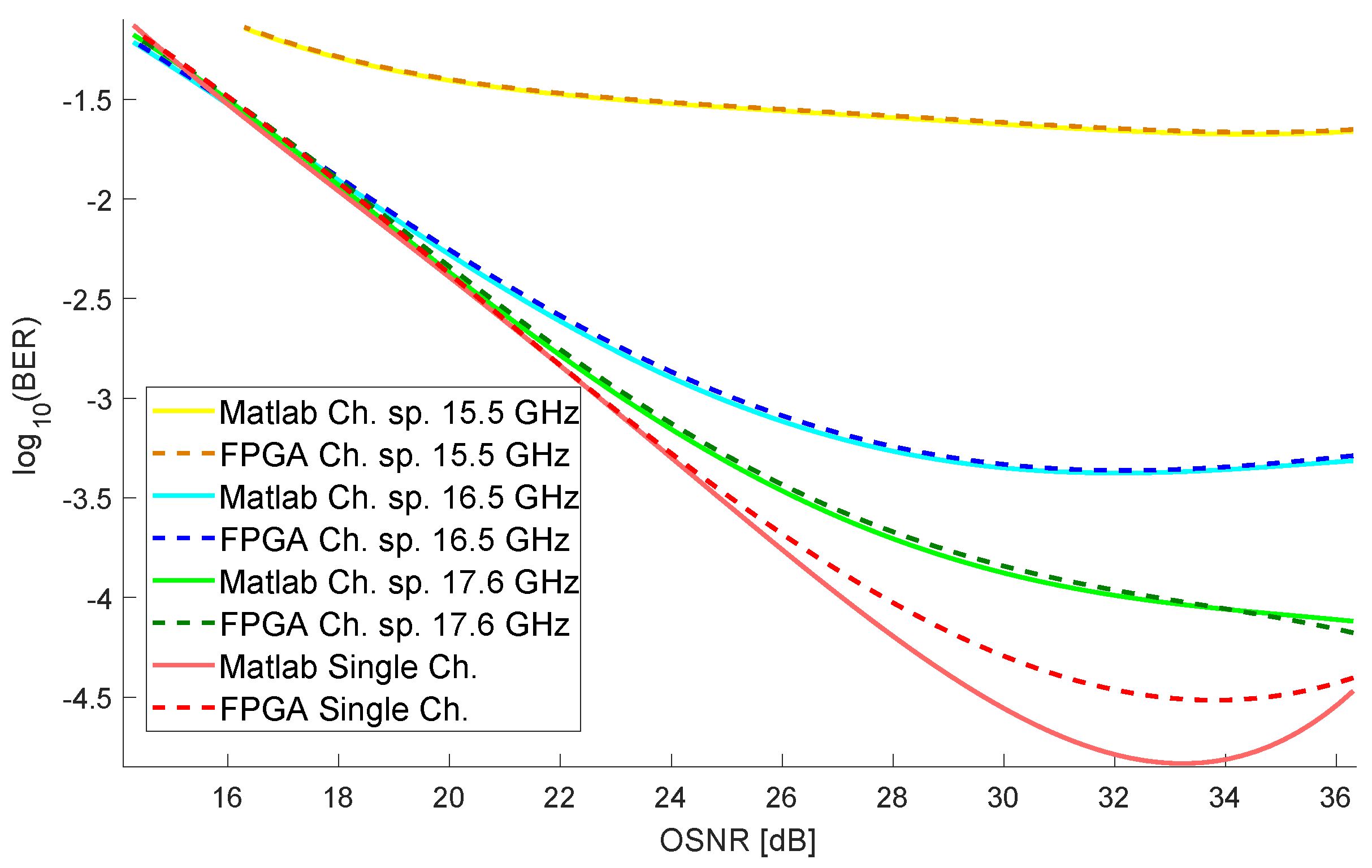
Finally, we validated the architecture using experimental data from a Nyquist-WDM gridless system affected by inter-channel interference (ICI). In this paper, we study the effect of ICI in a multicarrier optical transmission manifested in the constellation diagram as blurred data-symbols (or clusters) and intersecting each other. One of the objectives of this paper consists of associating each distorted data-symbol to the proper cluster despite the blurring, based on the estimation of belonging functions according to analysis of two-dimensional (2D) Euclidean distances following the principles of the k-nearest neighbor (KNN) algorithm. We validate the results comparing the real-time FPGA implementation and the MATLAB offline execution. Also, we verified our operations reduction technique comparing our 20 parallel cores KNN implementation against the modified KNN version. We consider that this work contributes to the implementation of machine learning techniques in real applications.
The document is organized as follows:
Section 2 presents an architecture that implements the scalable KNN algorithm to process multiple inputs in parallel in independent cores and presents a parameterized design with the possibility of use for multiple modulation formats. We propose modifying the KNN algorithm to reduce operations in m-QAM demodulators with a square shape in
Section 3.
Section 4 shows the experimental setup for data acquisition used to validate the design, the setup for hardware implementation on a low-cost FPGA, and a high-performance FPGA. In
Section 5, we show the results of the comparison between Matlab and FPGA implementation and the performance measures in terms of computation time and hardware resources. Finally, we present the conclusions of the work in
Section 6.
2. Scalable Multicore KNN-Based Demodulator
The KNN algorithm is a machine learning technique that consists of the comparison of the input data against data previously labeled with a specific class, called training data. This comparison is made by measuring the distance between the input data and the trained data. The training data with the lowest distance values are known as the nearest neighbors. The label that repeats the most among the K nearest neighbors is assigned to the input data. Algorithm 1 shows the execution of the KNN algorithm in a sequential computation. The algorithm starts with the loading of the training data with a length of L. The input of the KNN algorithm are symbols that come from a channel with m-QAM modulation, so each symbol is represented by a pair . Each data point contains three values: In-phase , quadrature , and the , which identifies that data point in a cluster of the m-QAM constellation. Also, the number of nearest neighbors used in the algorithm is chosen and stored in the variable K.
The Euclidean distance between the input symbol and all training data is calculated using the following expression:
, where the subindex
t indicates that it belongs to the training data, and
i is the array index taking values in the range 1 to
L. Please note that the distance calculation must be done
L times. In a hardware implementation, the square root is not calculated to reduce operations. The distances should be sorted in an ascending order to select the smallest distances. The
should be sorted simultaneously to get the
K labels for the nearest neighbors. The execution time of the sorting algorithms depends on the distribution of data, but time complexity is well known. In this work, we use the Merge Sort algorithm, whose time complexity is
. The distance array and the label array to be sorted are of length
L.
| Algorithm 1: KNN algorithm for demodulators |
 |
Algorithm 1 describes the pseudocode for the sequential implementation of KNN-based m-QAM demodulators. However, a hardware-based approach is necessary for accelerating the algorithm in a parallel architecture, enhancing the particularities of the m-QAM modulations and the independence in the operations of the KNN algorithm. For this, we define custom processing units.
2.1. Custom Processing Units for KNN-Based Demodulator
The custom processing units (CuPUs) helps to define more complex functions or high-level DSP operations. In hardware design the term Processing Element (PE) is often used as those elements that perform clock-independent operations and simple memoryless mapping in signal processing such as: add/sub, add/sub-and-shift, multiply, multiply-and-accumulate, butterfly, etc. [
26]. The CuPUs are not simple arithmetic operations on input data. They are complete routines that would imply in RTL an FSM with datapath. In this sense, the modules are closer to processing units than to processing elements. The word Custom was added to specify that these units already have optimization directives previously defined by the authors. The CuPUs perform basic independent operations, allowing the use of multiple components in parallel on hardware to improve the performance of the algorithm. For the KNN algorithm, a Calculate Distances CuPu calculates
L distances between the symbols and the training data. The
L training labels are sorted in ascending order according to the distance by a Sort Distances CuPU. Finally, the first
K labels are selected from the sorted label array, and the input symbol is labeled with the modal value, also inside a Calculate Mode CuPU.
2.2. Scalable Multicore Architecture Based on Cupus
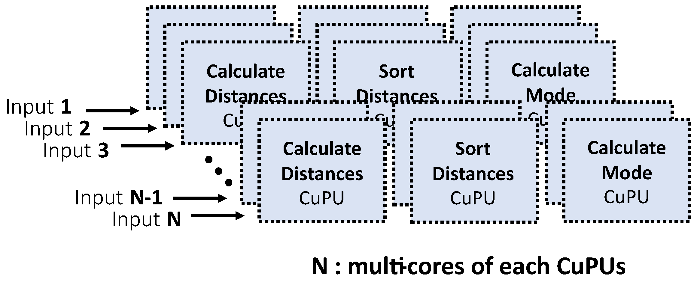
We propose a scalable multicore architecture based on CuPUs to improve the performance of the KNN algorithm. This architecture was designed for field-programmable gate array (FPGA), seeking to exploit the inherent parallelism that characterizes them. Scalable design is intended to be used in different FPGA targets. We define a parameter
N as the number of cores of each of the CuPUs used in the design, i.e.,
implies using 3 Calculate Distances CuPU, 3 Sort Distance CuPU, and 3 Calculate Mode CuPU, see
Figure 1.
We define N as the number of symbols entering the CuPUs for processing in parallel. Optimization directives such as pipelining, unrolling, and partitioning are added to the CuPUs to increase operational concurrency and improve performance. All High-Level Synthesis (HLS) tools use optimization directives for algorithm acceleration on hardware.
In a communications system, a transmitter sends symbols through a single channel or multiple channels to the receiver. For this reason, our design stores the symbol streams in buffers for separating into
N independent symbols for parallel processing in different CuPUs, see
Figure 2. The independence in the operations on each input symbol in the KNN algorithm allows the parallel processing of multiple channels using the same training data. In turn, each channel can be processed on multiple cores, expressing this as
, where
C is the number of channels, and
is the number of cores per channel.
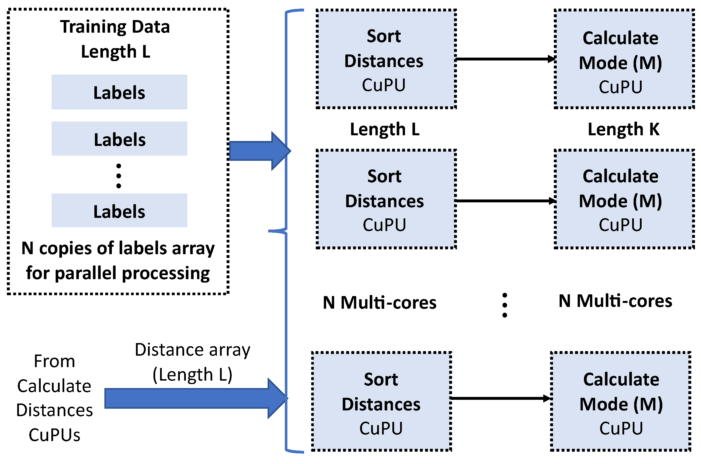
A Calculate Distance CuPU computes the distance between each symbol and the L training samples. The L distance calculations applied to each symbol are also independent operations allowing unrolling operation on the loop. The unroll directive increases the consumption of hardware resources, and when resources are limited, it is convenient to perform a partial unroll. The combination of unrolling and the pipeline directive allows the reuse of resources.
After the distance calculation, it is necessary to sort the L values of the distance array in the Sort Distance CuPU. The sorting algorithm used is a Restructured Merge Sort [
27], and it is a sorting algorithm optimized through directives in HLS for implementation in FPGA. The training data labels are sorted simultaneously with the distance array.
N label array copies guarantee the parallel processing in the
N cores, see
Figure 3.
The Calculation Mode CuPU selects the first
K labels from the sorted array, see
Figure 3. The modal value serves to assign the right cluster of the constellation to the input symbol. In m-QAM schemes, there are
m different labels.
This section presented the design of a scalable multicore architecture based on CuPUs. The architecture considers the particularities of communication systems when implementing real-time demodulators based on the KNN algorithm on FPGAs. The design has a focus on m-QAM, but it is not limited to this type of modulation. In the following section, we propose a modified version of the KNN algorithm to reduce the number of operations bringing the focus closer to m-QAM based on the constellation shape.
3. Modified KNN Algorithm to Reduce Operations in M-Qam
The implementation of the KNN algorithm presented in the previous section can be modified to take advantage of the symbol geometric distribution seen in a constellation diagram. QAM schemes have characteristics that differentiate them from other applications that use the KNN algorithm. In this case, the inputs are symbols represented as a pair of real numbers. The symbols arrive at the receiver in a different position inside constellation. It happens because of noise and distortions in the travel through the channel. The recovery possibility of the symbols depends on how far they are from the initial position. In a successful transmission, we expect the symbols in certain zones of the constellation to consider recoverable. We propose the following hypothesis:
Hypothesis (H1): For an input symbol to be correctly classified using the KNN algorithm, it must belong to the cluster-block to which the nearest ideal cluster belongs.
Moreover, we present the following definition:
Cluster-Block: It is an 8-connected neighborhood of nine clusters: a central cluster and the eight clusters surrounding it.
Algorithm 2 shows the modified KNN for m-QAM. The algorithm adds two steps before step 1, seen in Algorithm 1. Step 0.1 calculates the Euclidean distance between the input symbol and the
m clusters of the ideal constellation. According to our hypothesis, the cluster with the closest distance or one of the 8-connected neighbors contains the input symbol label. Because of this, in step 0.2, we carry out the labels corresponding to the cluster-block. In this modified KNN algorithm, the training data are organized by labels and and the memory addressing is established to access only the positions corresponding to the selected Cluster-Block.
| Algorithm 2: Modified KNN algorithm for m-QAM demodulators |
 |
The algorithm considerably reduces operations by using only the training data associated with a cluster-block.
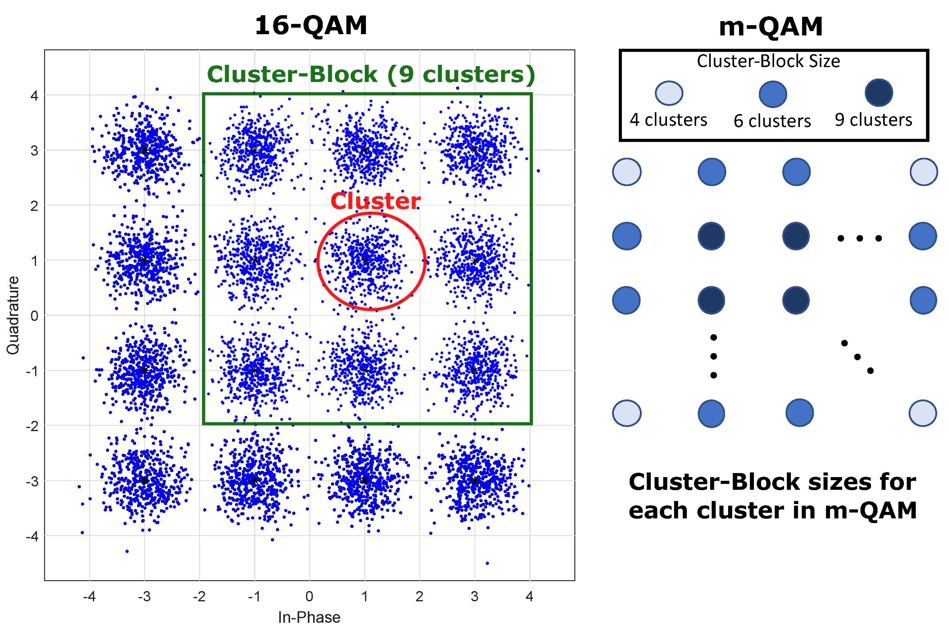
Figure 4 shows a square-shaped constellation of size
. The cluster-block size varies depending on the constellation position, but we always have a size of 4 clusters for the blocks at the corners, 6 clusters for the blocks at the edges, and 9 clusters for the blocks in the center of the constellation. The figure shows an example of the application of cluster-blocks on a constellation diagram for 16-QAM. It also follows that for constellations without corners, we would have values of 5 and 8 clusters for the blocks near the corners. The other sizes are 6 and 9 clusters, as in the constellations with corners.
The algorithm reduces the L training data in Calculate Distance CuPU and Sort Distance CuPU. In this case, we express the total length of training data as , where is the length of the training data for a cluster, and remember that . In this way, L is much bigger than the number of training data for the biggest cluster-block.
Calculate Mode CuPU depends on the value of K, and the reduction in L does not affect it, but this CuPU is the least amount of operations performed within the KNN algorithm because it assumes .
Algorithm 2 implementation on FPGA uses the CuPUs as in Algorithm 2, but with a smaller training data length due to reduction of operations, as described in this section, i.e., we propose the implementation of the modified KNN algorithm using a scalable multicore architecture to process the input symbols in parallel, as in Algorithm 1. The CuPUs were implemented with optimization directives to increase the concurrency of operations within each processing unit.
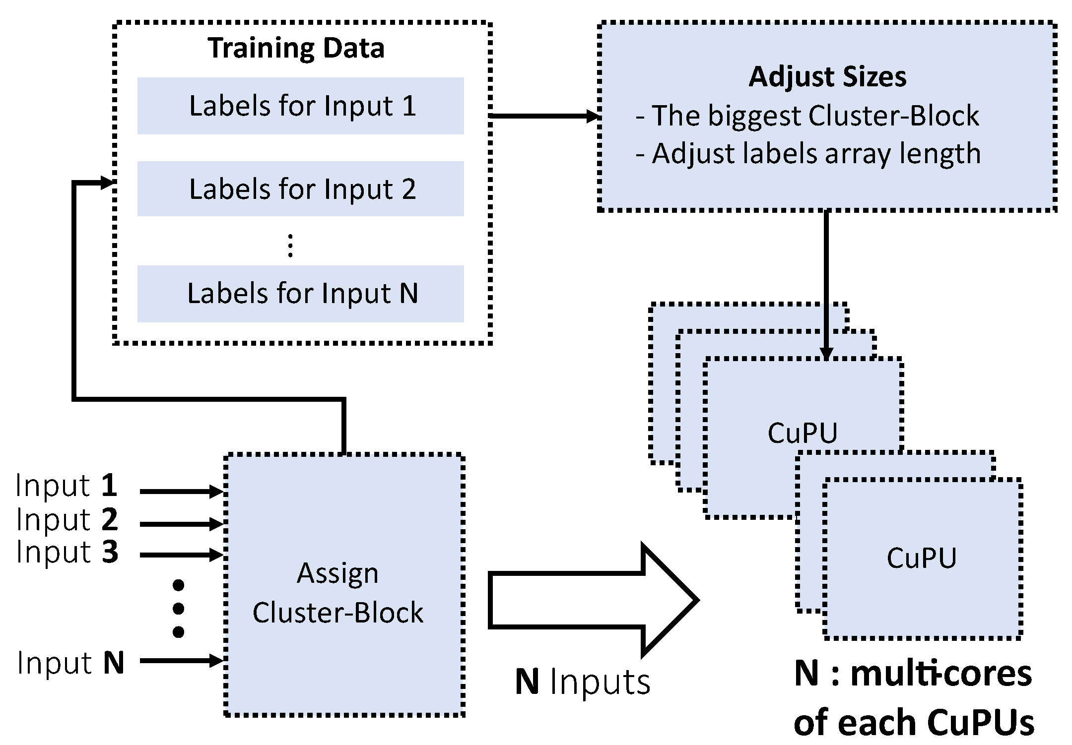
Figure 5 shows the architecture of the algorithm for the modified KNN. A new processing unit is attached to performs the Cluster-Block assignment to the input symbols. This block measures the distance to the ideal constellation and selects the training data taking only those belonging to the Cluster-Block.
The CuPUs are built to independently compute N inputs of the KNN algorithm taking full advantage of the parallelism. For the same function, the architecture uses copies of the same CuPU that are executed in parallel. An implementation of Algorithm 2 using the previously designed multi-core architecture requires adding a module to adjust the training data sizes for each symbol. In this version, each of the N symbols is assigned to a Cluster-Block with three different size options (4, 6, 9). Additionally, the amount of training data for each tag may vary depending on the application. A version without size adjustment would eliminate the synchronization of the CuPUs with outputs at different times, depending on the input symbol’s value. In this work, we want to take advantage of the highly parallelized and parameterized architecture of Algorithm 1, so we adjusted the data size to the largest value for the N label arrays. However, we hope in future versions to design a structure that includes the synchronization stage to take advantage of the reduction of operations that allows the modified KNN algorithm.
6. Conclusions
In this work, we presented a multi-core architecture for real-time implementation of KNN-based demodulators. The design takes advantage of the operations’ independence applied to the symbols coming from a communication channel. The design allowed selecting N input symbols to configure N parallel processing cores. These cores contain custom processing units (CuPUs) implemented with optimization directives to increase concurrency within each core. The implementation was performed using a high-level synthesis (HLS) design methodology, simplifying the selection of m-QAM formats and the KNN parameters. This version of KNN could be used in formats other than m-QAM modulation because KNN results depend on the training data and not on the constellation’s shape.
Additionally, we proposed a modification of the KNN algorithm to improve the performance of the hardware implementation. In this case, the modulation format does concentrate on square-shaped m-QAM constellations. We define Cluster-Blocks to significantly reduce the number of comparisons and sortings on the training data. The modified KNN algorithm shows a decrease in computation times concerning the first KNN version. For the hardware implementation, we use as a base the multi-core architecture to preserve the advantages in scaling and parameterization.
For future work, we propose testing KNN implementations with data from other experimental setups and different modulation formats. In addition, we suggest increasing the design exploration for the KNN algorithms to obtain better processing times, for example, exploring the impact on the use of fixed-point numerical formats with a lower amount of bits or efficient memory management techniques. Finally, we propose exploring this type of modification in other machine learning algorithms.


