Abstract
The fabrication of underwater devices is necessary for the exploration of water environments and interactions in the Human–Computer Interaction (HCI) field. However, there are fewer approaches to support prototyping used in water environments. The existing prototype methods lack systematic waterproof treatments and provide insufficient software for balance and buoyancy analysis. To address these limitations, we present ElectroPaper, a new approach for the design and fabrication of prototypes used in water environments (surface or beneath) with paper-based electronic interfaces with a crease layer, hardware distribution layer, and hollow-out layer to support physical properties, such as waterproofing, foldability, and conformability. The approach includes a computational design tool for assisting in balance analysis, three-dimensional (3D) model unfolding, and circuit drawing. We describe the design and fabrication process and provide several example applications to illustrate the feasibility and utility of our approach. ElectroPaper provides an inexpensive and effective medium for the fabrication of customized digital prototypes for water environment use.
1. Introduction
Recently, there is a focus on water interactions and underwater devices in the Human–Computer Interaction (HCI) field due to their extensive applications in the exploration of water environments, aquatic recreation, and installation art. These developments cannot be separated from prototypes, which play an important role in concept design and system iteration. However, most of the prototype approaches do not consider this special environment, and most electronic circuit fabrication is unsuitable for water environments. Methods, like 3D printing, are time-consuming, involve many design iterations, and require considerable testing. Challenges, such as waterproofing, balance, buoyancy, and materials, make the design and fabrication complicated and expensive.
Paper and papercraft methods are used in various scenarios, such as HCI, robotics, and scientific research. Researchers have explored the affordances of paper with Do It Yourself (DIY) electronics to create interactive books [1,2], paper actuators [3], origami robots [4], and tangible paper interfaces [5]. Paper is inexpensive, lightweight, environmentally friendly, and foldable, with myriad methods of creative expression through the medium itself [6]. We rely on these advantages to fabricate the prototypes used in water environments, and develop ElectroPaper, a low-cost and effective approach to implement them.
Several issues should be considered when making paper-based electronic prototypes for water environment use: (1) materials should be waterproof and able to protect the electronics inside; (2) materials should be foldable to fulfill the design requirement; (3) the prototype should be durable and last long enough to complete the test; and, (4) balance is essential, and it must be evaluated during fabrication.
To address these issues, we designed a paper-based electronic interface that can be used in water (Figure 1a). The multilayer structure includes a crease layer, hardware distribution layer, and hollowed-out layer. The crease layer and hollowed-out layer are waterproof. Between them is the hardware distribution layer, where electronic components are arranged and connected by copper wires. This structure ensures the high functionality of waterproofing, foldability, and durability of the interface. We created a design tool that was based on Rhinoceros 3D software for users to build prototypes. In the software, the user builds a 3D model and then places electronic components on the surface. The model’s balance can be evaluated, and the model adjusted based on the results. The 3D model is flattened using origami unfolding algorithms [7]. The user can then draw wires based on the circuit schematic, and export four digital files for fabrication. Our approach is low-cost, efficient, and functional. We believe that it will spawn new designs and applications of underwater devices.
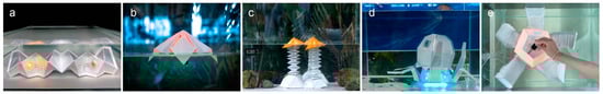
Figure 1.
(a) Waterproof, foldable paper-based electronic interface of ElectroPaper system. Example applications: (b) a paper device to detect water quality; (c) a decorative device that floats according to the water temperature; (d) a camouflaged camera to capture underwater scenes; and, (e) a deformable robot for entertaining interaction.
We demonstrate our fabrication approach through a series of applications (Figure 1), including water environment detection, underwater robots, entertainment, and water environment decoration, with unique attributes, such as buoyancy, water quality, and water temperature. Our main contributions are, as follows:
- We provide a low-cost prototype approach for paper-based electronic devices suitable for water environments. Tests verify its waterproofing, durability, and foldability.
- We present a design tool for balance analysis, 3D model unfolding, and circuit drawing, which simplifies the design and fabrication process.
- We demonstrate a series of water-related applications created using our method, highlighting the efficiency, usability, and functionality of our approach.
2. Related Work
2.1. Underwater Devices and Interactions in HCI
Interactions in water environments remain largely unexplored, yet they hold great development potential. With advances in technology, such as communication and waterproofing, underwater devices and interactions have seen increased focus. Oppermann et al. [8] and Yamashita et al. [9] explored the use of Augmented Reality (AR) equipment in underwater education and entertainment. Pell et al. [10] proposed a gravity well to support underwater play through water-movement interaction. Choi et al. [11] designed a wearable device for team underwater interaction. Many researchers have combined HCI and a water environment for novel user experiences [12,13,14,15], or focused on interactions between humans and underwater robots. Ukai et al. [16] made a buddy robot that could recognize, follow, and present information to a swimmer. Chutia et al. [17] provided an overview of underwater robots and their progress. Raffe et al. [1] proposed guidelines for the design of underwater equipment and player–computer interaction [18].
Unpredictable and hazardous conditions that make it difficult to realize a general method to prototype equipment used in the water environment. Although digital manufacturing tools, such as rapid prototyping printers, enable the production of underwater equipment, they still have difficulty integrating with the water environment for underwater interaction [18,19]. Moreover, the challenges of waterproofing, materials, and fabrication make it difficult for ordinary people to produce underwater devices. We facilitate the creation of low-cost, functional underwater devices from common paper materials.
2.2. Electronic Paper Prototypes
Many researchers have recently focused on the use of paper in the HCI field, as paper is thin, lightweight, ubiquitous, and inexpensive [20]. Fuchs et al. [21] explored new types of wearable devices. Zheng et al. [5] uncovered the characteristics of paper as a tangible interface. Chang et al. [22] explored the potential of kirigami- and origami-based structures in sophisticated haptic feedback through simple cut-and-fold fabrication techniques.
The integrated fabrication of body structures, actuators, sensors, and electronic circuits into the digital system is an open problem [23]. Advanced techniques make paper circuits available for creative interactions and applications [23,24]. There is already a focus on the design of electronic paper, which integrates electronic components to support digital interaction. Researchers have combined paper and electronics and presented toolkits for the design of interactive papercraft [6,19,25]. Oh et al. [20,26,27] presented paper mechatronics, which combined electronics and computation with traditional papercraft. Researchers have explored paper interaction with materials and technologies, such as shape memory alloy [28], electrical actuation [3], and retro-reflective material [29], which allow for flexible manufacture. Rus et al. [30] introduced paper-structured robotics, which combines scalable geometric structures, mechanical structures, and electronic components, and then discussed its use in different fields.
Existing research has shown how to make paper-based prototypes by integrating electronic circuits with paper material, but scant attention has been paid to its application in a water environment. We use various paper materials, such as fiber-based copy paper, polymeric film-based synthetic paper with the properties of being waterproof, wear-resistant, foldable, and conformable, and then propose a multilayered, paper-based, electronic interface to create prototypes that are suitable for water environments.
2.3. Papercraft Fabrication Tools
As the range of papercraft applications has expanded, the problem of folding has assumed greater importance [31]. Lang et al. [31,32] proposed a tree method to design a crease pattern folding flat into a base with any number of flaps. Mitani et al. [33] proposed a method for producing unfolded papercraft patterns from triangulated meshes by means of strip-based approximation. However, these methods might be too difficult for novices to design cutout sheets. Based on these unfolding algorithms, researchers have developed papercraft design tools that enable novices or experts to create paper-folding without technical restrictions [34,35,36,37]. Some design tools also provide papercraft design assistance, such as waste reduction [32], circuit construction [19], and mobility [6,38].
Being derived from origami art, origami mathematics proves that any geometry can be theoretically simulated by origami [36], and paper has become an excellent medium for prototyping and crafting with good foldability. Inspired by previous work, we present a design tool that leverages algorithms to flatten 3D models to two-dimensional (2D) representations, which is suitable for papercraft. Our design tool demonstrates customized functions for water environments, and allows users to analyze the balance state and working conditions of prototypes, such as floating, suspending, and sinking, to simplify testing and improve the usability.
3. ElectroPaper: Design and Fabrication
In this section, we describe the ElectroPaper system, including materials, paper-based electronic interfaces, design software, and fabrication approach, so as to provide a low-cost and effective method to build electronic prototypes for use in water environments.
3.1. Materials Introduction
3.1.1. Paper Materials
We used several paper materials, including ordinary paper (copy paper) and synthetic paper (polymeric film with paper properties). Ordinary paper is not waterproof or durable in the water environment to guarantee the regular work of the electronic prototype. Therefore, we tried to find materials or ways with traditional papers’ advantages and the quality of waterproofing and durability.
We tested several methods, such as waterproof synthetic papers, spraying waterproof chemicals, and waxing, and then compared their waterproofing, foldability, durability, price, and process. Table 1 shows the results of pilot studies, evaluating features and ability on a scale of good, medium, or poor. We find that spraying waterproof chemicals is effective, but it is limited by foldability and durability. Waxing does not provide stable waterproofing, and waxed paper cannot be folded. We tested two types of waterproof paper. Polyethylene terephthalate (PET) paper (Hang Tang, PET synthetic paper) is adhesive and performs better than polyvinyl chloride (PVC) paper (Hang Tang, PVC synthetic paper). Waterproof synthetic papers require no chemical or physical processing. We decided to use PET paper as the substrate of our first layer, as it is adhesive, waterproof, tear-resistant, and foldable, and it supports laser printing.

Table 1.
Comparison of waterproof materials and methods.
We used a coated paper with one side that is covered with biaxially oriented polypropylene (BOPP) film (Han Tang, BOPP coated paper) to increase its toughness and wear-resistance. This material is not waterproof, and it formed the second layer, where the circuit was attached. The coated paper was stuck together with the first layer. It can be removed more easily than ordinary copy paper, which could be convenient for its adjustment or replacement. This commercial paper has a price of $0.10/A4 sheet.
We used a waterproof oriented polypropylene (OPP) paper (Flower Season, OPP paper) (Table 1), which is collapsible and translucent, as the third layer’s substrate. It allows users to directly view and check the hardware in the second layer. Unlike the first layer, this layer is not sticky, and it is easily removed for reuse without damaging the circuit.
3.1.2. Waterproof Shells
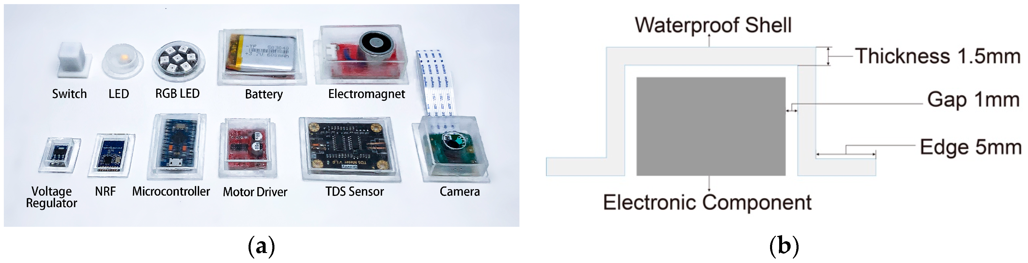
Waterproofing is essential for electronic prototyping that is applied to water environments. Most of the electronic components that we use are standardized, small in size, and likely to be reused in the circuit. These features mean that it is complicated and time-consuming to provide waterproof protection for every component with paper folding. Therefore, we use reusable shells with stable waterproof effects to protect the electronic components. We measured the size of the needed electronic components and customized waterproof shells (Figure 2a) using a common reverse mold method. The mold is made with silica gel, and we use it to make waterproof shells from epoxy resin. The shells have a standard size (5 mm edges, 1.5 mm thick, 1 mm gap between shell and electronics) and can be reused, as shown in Figure 2b.
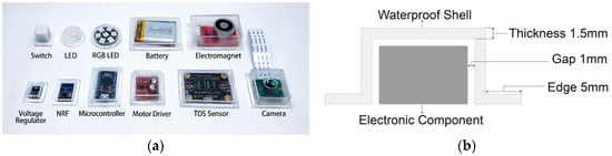
Figure 2.
(a) Waterproof shells. The soft silicon shell of the switch is different from the others, and supports its ups and downs; and, (b) standard for making waterproof shells.
3.2. Structure of Paper-based Electronic Interface
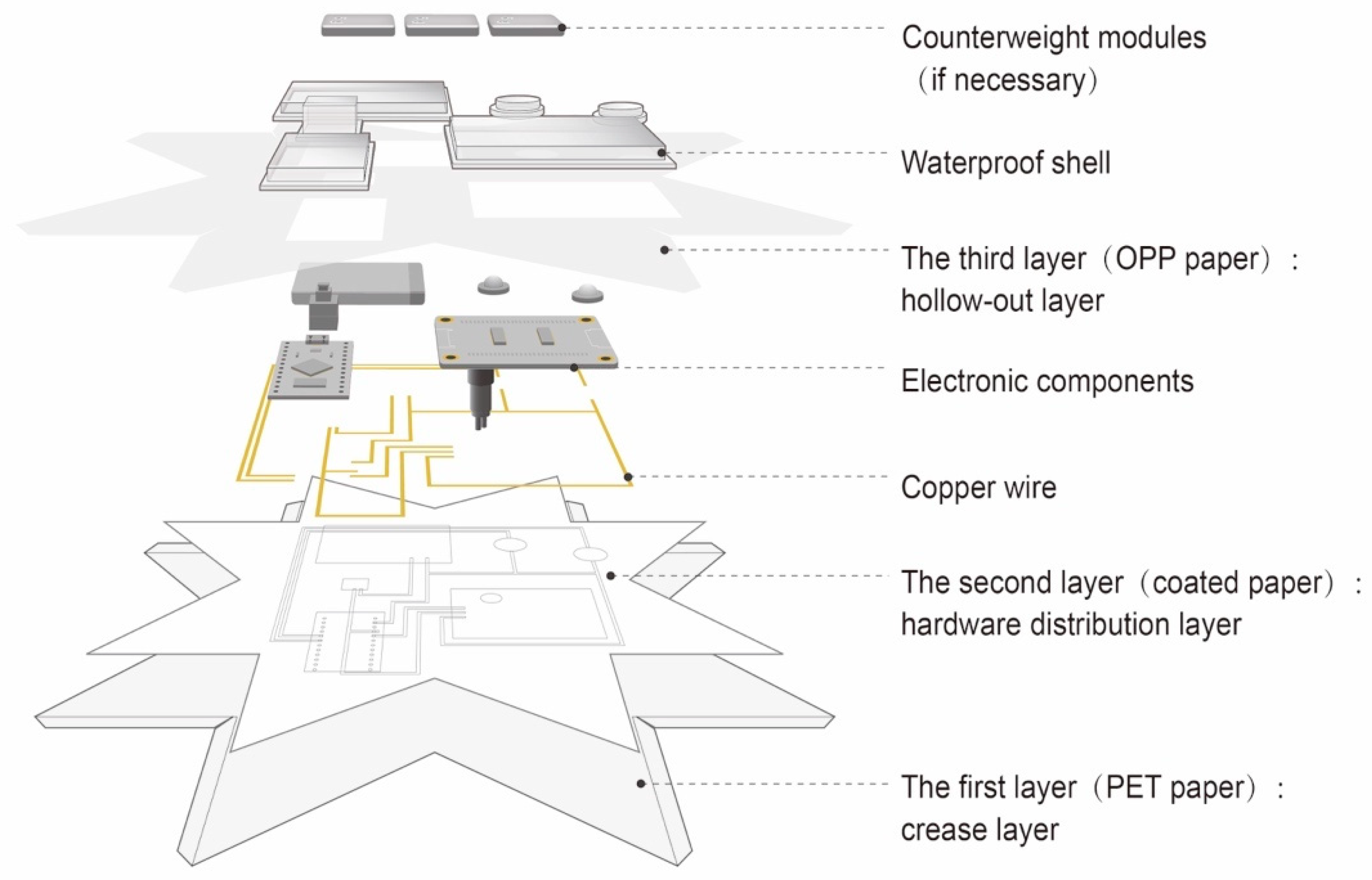
We introduce the multilayer structure of the paper-based electronic interface, which includes three layers of different paper materials (Figure 3).
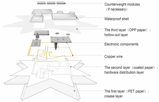
Figure 3.
Multilayer structure of the paper-based electronic interface.
Waterproof paper (PET) is the first layer, which can be immersed in water for a long time. This layer presents the crease lines for folding, which can be laser printed on the paper. The hardware distribution layer is made of coated paper (BOPP). The copper wire and electronic components are fixed on the non-coated side. The hollow-out layer, with translucent paper (OPP), can seamlessly cover the second layer, except for the position of the electronic components. The layer is hollowed out for the electronic components, in order to make the interface flat and easy to fold.
Waterproofing is essential in electronic prototyping that is used in water environments. The first and third layers, which contact water, are waterproof, and they are glued together with waterproof adhesive. The waterproof shells are glued to the third layer to cover the electronic components. For better waterproofing, the outer contour sizes of the first and third layers are the same, and the middle layer is smaller. After our test, the outer contour of the second layer was shifted to the inside by at least 8 mm, which will have a stable waterproofing effect. After stacking, the thickness of the three-layer paper interface (excluding electronic components and waterproof shells) is 0.3 mm, and it has excellent folding ability.
The electronic components are commercially available. The wires are made from 0.05 mm copper tape and they can be obtained by simple processing. We also tested other conductive methods. For example, screen printing is cumbersome, high cost, and not suitable for fabricating customized circuits. Moreover, it is not easy to control the amount of ink when printing, and the conductive ink becomes hard when dry and breaks when folded, so its conductivity is unstable. Inkjet printing is a new and simple circuit-making method, but it is expensive. Silver foil is another method, which is hard to handle and can cause circuit failure when folded. Overall, copper tape conducts electricity well, folds easily, and costs little.
3.3. Design Software
The design software is implemented in Rhinoceros 3D with Grasshopper and Human UI plugins. Different from other design software, our tool adds electronic components and circuits to the model design phase, provides buoyancy and balance analysis of the 3D models, achieves the unfolding of 3D models into 2D planar sheets, and generates folding creases to simplify manual fabrication. The software effectively improves the feasibility of prototypes.
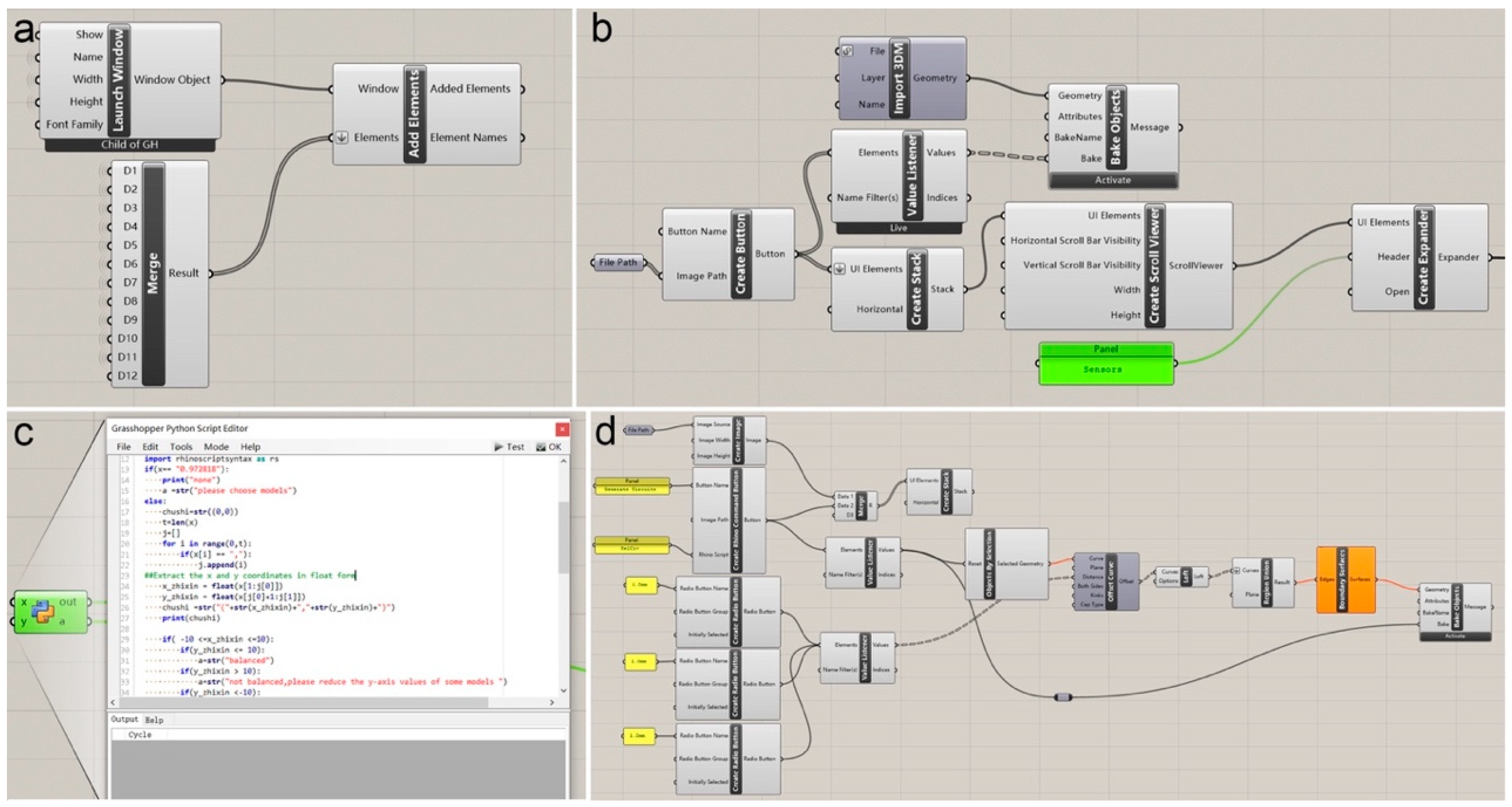
We built the design tool’s fundamental framework based on the functions of Launch Window, Add Elements, and Merge of Human UI (Figure 4a). It includes five parts: component library module, balance analysis module, 3D unfolding module, circuit drawing module, and file export module. The component library module is created with Create Button, Import 3DM, etc. (Figure 4b). When the user clicks on a component in the library, its 3D model can be imported. The balance analysis module runs code in the Grasshopper Python Script Editor to analyze the working state and balance of modules (Figure 4c). In order to build the 3D unfolding module, we use the Command Line function of Grasshopper to call the unfolding algorithm provided in ref. [7], achieving the target 3D object flattened to 2D patterns that will be imported back into Rhinoceros 3D. As for the circuit drawing module, the Create Rhino Command Button is used to call Draw Multiple Curves functions in Rhinoceros 3D. It then combines Offset Curve, Boundary Surface, etc., to achieve the circuit drawing function (Figure 4d). Finally, the file export module was built through the Export Objects Component in Human UI to export 2D patterns into printable files.
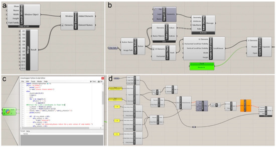
Figure 4.
Software building: (a) fundamental framework built with Human UI; (b) grasshopper wiring diagram of the component library module; (c) code of the balance analysis module; and, (d) grasshopper wiring diagram of the circuit drawing module.
3.3.1. Component Library
We built a component library in the software, including electronic components, waterproof shells, paper structures, and counterweight modules, and users can add other components. Data, such as the weight and dimensions of electronic components and waterproof shells, are predefined. The software can read the model’s volume, volume centroid, hardware center of mass, and other parameters to analyze its buoyancy and balance.
3.3.2. Primitive Structure
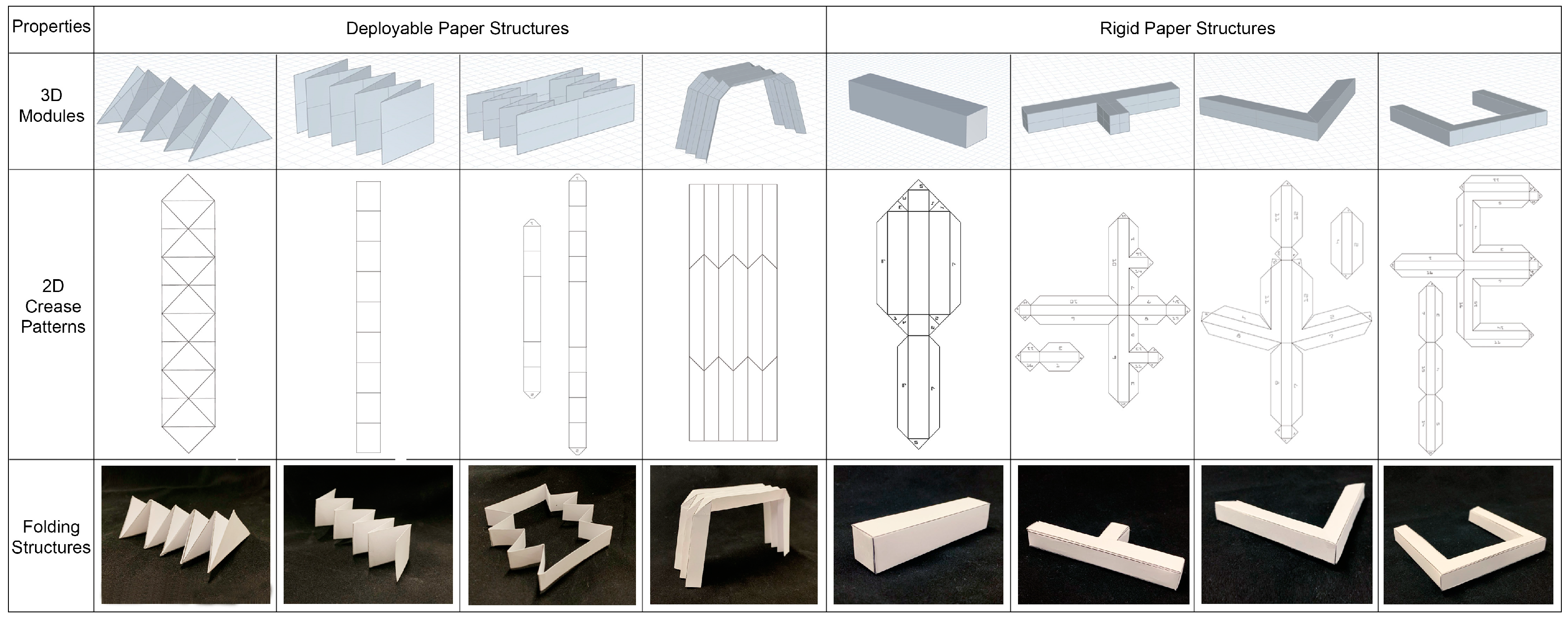
We provide multiple groups of paper structures in the software library based on previous origami research. These can serve as 3D model references for prototype designs. The deployable structure supports the transformation of the prototype. The rigid structure can be used as a supporting or stationary form in the prototype. Figure 5 shows the 3D models of the paper structures, which are developed into a 2D crease pattern, and the paper prototypes can be folded by referring to the 2D patterns. Below, we show water temperature sensing and starfish robot designs based on the structures that are shown in Figure 4.

Figure 5.
Paper structures in component library.
3.3.3. Software Workflow
We show the software workflow in Figure 6.
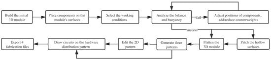
Figure 6.
Software workflow.
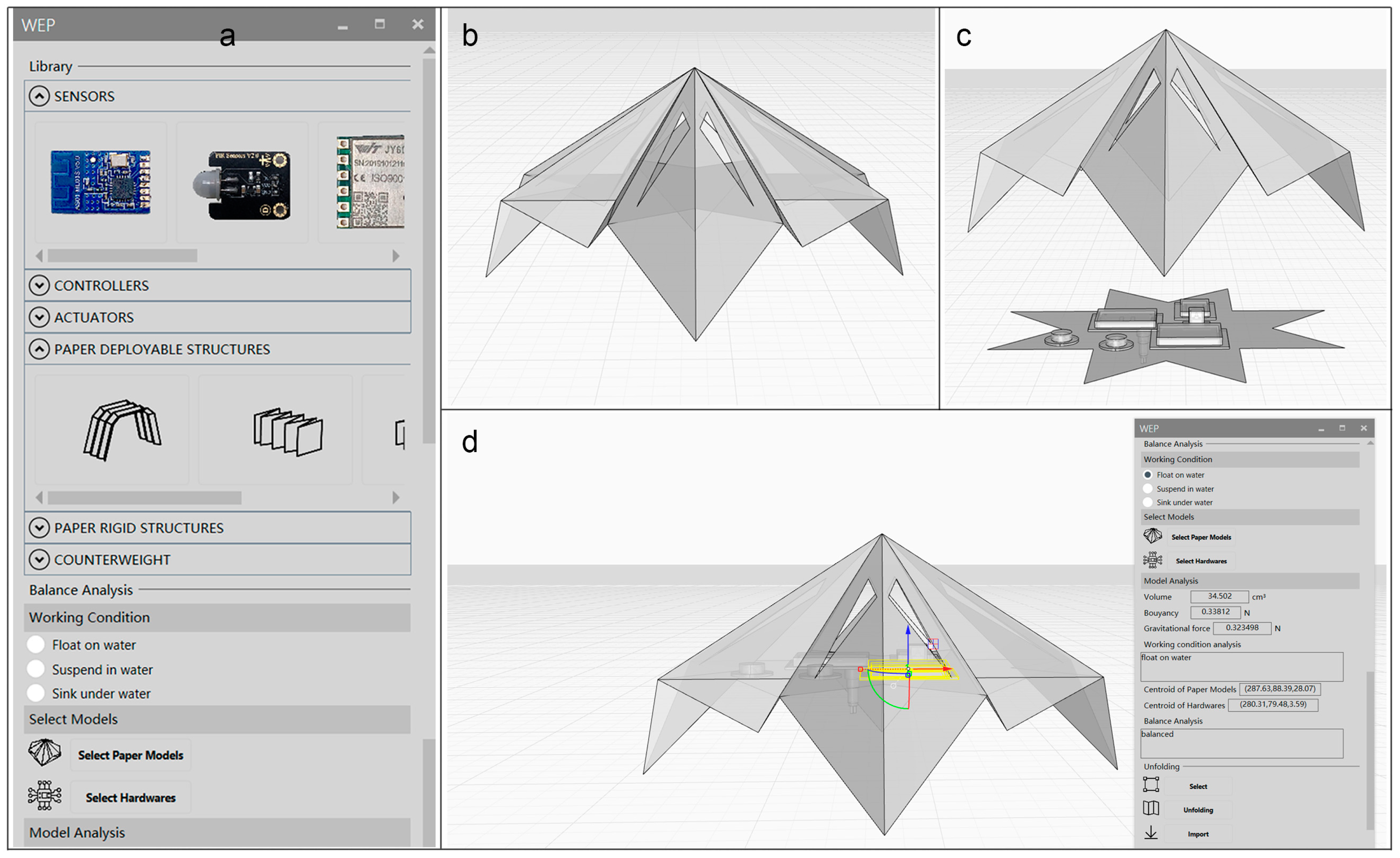
(1) Model Building. In this step, the prototype model is built and the relevant components are placed on it. The Rhino modeling software can be used to build the initial model (Figure 7b), and the paper structure model in the component library can be used for assistance. The user selects the components from the library and then places them on the surfaces of the model (Figure 7c). We also provide waterproof shell models. The user can manually adjust the positions of the components.

Figure 7.
(a) Component library; (b) build initial model; (c) place components on model surface; and, (d) analyze balance and buoyancy.
(2) Balance Analysis. Integrating balance analysis into the model design can effectively improve the effectiveness of the prototype and simplify the iterative process. The user selects the model’s working conditions from “float on water”, “suspend in water”, and “sink under water” (Figure 7d). The models and components are selected for buoyancy and balance analysis. The software shows the results and suggests adjustments. The user can change the 3D model’s shape, rearrange the positions of electronic components, and change the numbers of counterweights to meet design goals.
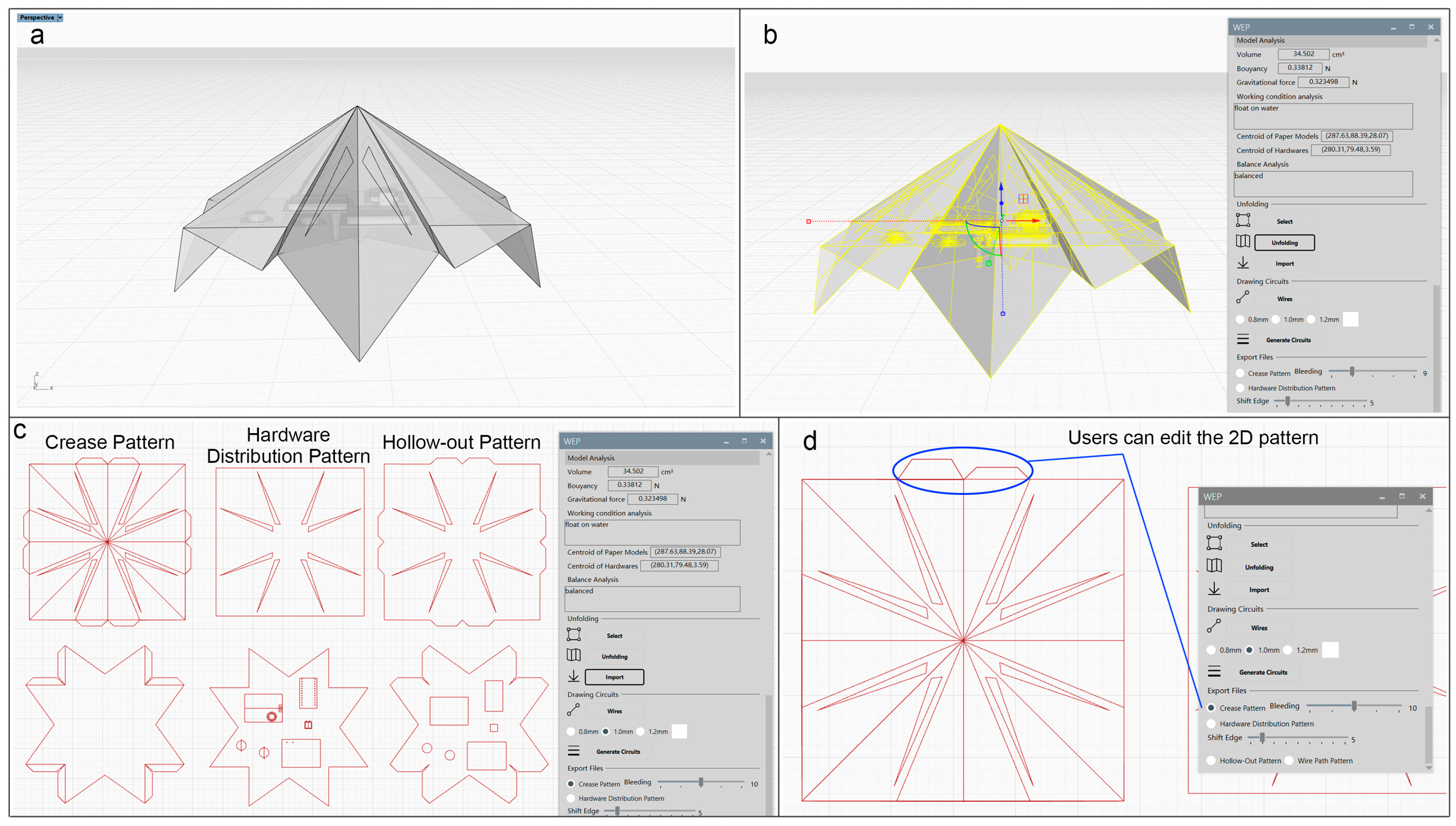
(3) 2D Patterns Generation. Origami-based flattening and paper model unfolding algorithms [7] are integrated into our design tool in Rhinoceros 3D, enabling 3D objects to be flattened to 2D patterns. Model surfaces should be intact, without hollowing out, and the user must patch the hollow surface before flattening (Figure 8a). Subsequently, the 3D model can be flattened to generate crease, hardware distribution, and hollow-out patterns (Figure 8b,c). The crease pattern shows the folding trace, cutout sheets, and hollow-out trace for guiding manual fabrication. The hardware distribution pattern presents the outline paths of the electronic components and counterweights. The hollow-out pattern presents the outline path of the electronic components, which must be cut. Our tool allows for customization, so that users can edit and parameterize the patterns, such as the size and shape of the paper flaps (Figure 8d).

Figure 8.
(a) Patching hollow surfaces; (b) select and unfold three-dimensional (3D) model; (c) generate three kinds of patterns; and, (d) users can edit two-dimensional (2D) patterns.
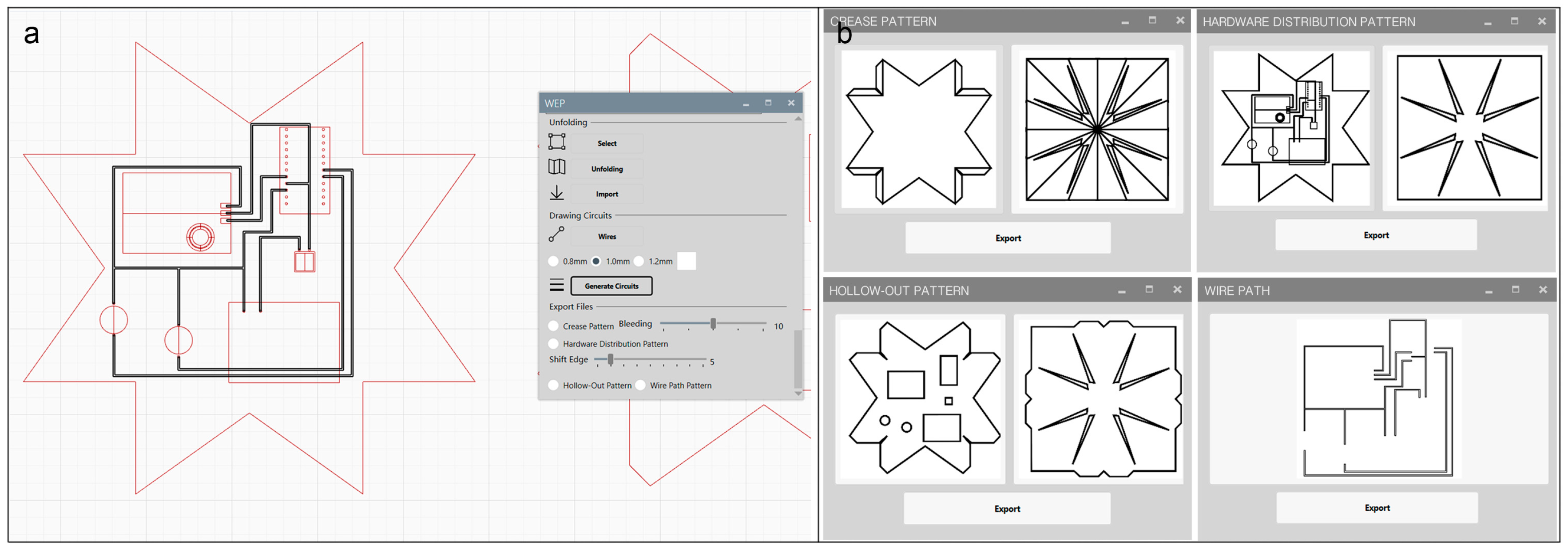
(4) Circuit Drawing. To provide a variety of functions, our paper circuits contain components, such as batteries, sensors, actuators, controllers, and communication modules. The outline of each electronic component and the locations of connection points are displayed in the 2D hardware distribution pattern, allowing for the user to directly connect points to draw circuits (Figure 9a). The connection lines are non-overlapping, which allows for direct processing of the wiring path by the laser cutter. The parametric design of our tool also enables the user to adjust the width of the connection wire (Figure 9a). In this step, the software will generate a new hardware distribution pattern that shows the paths of electronic components, counterweights, and copper wires. Finally, the user can export fabrication files, including the crease pattern, hardware distribution pattern, hollow-out pattern, and wire path (Figure 9b).
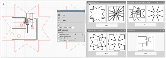
Figure 9.
(a) Circuits drawing. Draw copper wires on the hardware distribution pattern and generate a new pattern; (b) Export files.
Our software is a design tool for creating underwater devices that are based on papercraft. It combines the functions of modeling, balance analysis, 3D model unfolding, and circuit drawing, which can simplify the design and fabrication and improve the usability of the prototype.
3.4. Fabrication Approach
All of the materials are commercially available and they can be processed by common tools, such as a laser cutting machine and printer. Users can effectively make waterproof paper-based electronic interfaces and prototypes of underwater devices at a low cost. This approach has six steps.
Design 3D models in the Software. The user designs and builds the 3D model in the software, arranges the components, and tests its balance. The 3D model is unfolded into a 2D patterns, on which the user draws wires. The software generates four digital files.
Print and Cut. Four materials must be processed. First is the crease layer (Figure 10a). The user can print patterns on the waterproof side of the PET waterproof paper with a laser printer. The paper is cut along the outline path with a laser cutter (Figure 11a). Subsequently, the user cuts the second layer’s contour on the opposite side of the first layer (Figure 10b). Only the protected side of the paper is to be pierced. The inner part of the protected paper is removed (Figure 11b). The second part is the hardware distribution layer (Figure 10c). The user prints the patterns on coated paper, cuts along the contour with a laser cutter, and then pastes it on the sticky side of the waterproof layer (Figure 11c). Third is the hollow-out layer (Figure 10d). The user cuts the translucent paper along the outline path and the electronic components’ hollow-out position. We use copper tape for the electric wires (Figure 10e), which is sticky on one side and can be cut with a laser cutter (Protolaser U3, LPKF) [39] or a carving machine (Silhouette America SILH-CAMEO-4, CrafterCuts).
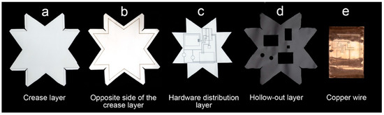
Figure 10.
Materials that have been processed. (a) Crease layer; (b) opposite of the crease layer; (c) hardware distribution layer; (d) hollow-out layer; (e) copper wire.
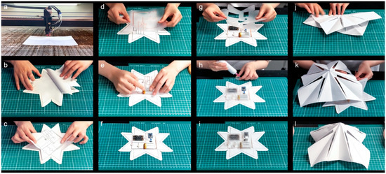
Figure 11.
Fabrication: (a) print and cut; (b) remove the inner part of the protected paper; (c) paste the hardware distribution layer on the sticky side of the waterproof layer; (d–f) circuit fabrication; (d) copper wire transfer; (g–i) superpose layers; and, (j–l) fold and assembly.
Circuit Fabrication. The previously cut copper wire can be transferred to the hardware distribution layer through the transfer paper (Aihua, PVC) (Figure 11d). The electronic components are taped to the marked position in the hardware distribution layer (Figure 11e) and then bonded to the copper wire by the conductive adhesive (Ausbond, 3811).
Superpose Layers. The protected paper is removed from the waterproof paper, and the transparent hollow-out paper is glued to the waterproof paper (Figure 11g). Custom shells are placed on the electronic components (Figure 11h) and then glued to the hollow-out layer with waterproof glue (V-705, silicon rubber) (Guangdong, China). The user sticks the counterweight to the specified position if necessary. At least 30 minutes are required for the glue to dry.
Fold and Assembly. The user folds the interface that is based on the creases and sticks paper interfaces together using waterproof tape (Darit Tape, PVC) (Guangdong, China) (Figure 11j–l).
Patch and Decorate. Check the condition of the prototype. The user can apply decorations or make repairs on paper interfaces.
4. System Evaluation
4.1. Testing Waterproofing
Waterproofing is crucial to underwater equipment. The international industrial waterproof grade standard IPX [40,41] requires that equipment applied in water can still be used after immersion at a specific pressure for a specified period of time. ElectroPaper is the first paper-based electronic interface to examine the waterproof ability. The interface that we tested includes a battery, switch, controller, and RGB LED, which can shine blue, green, and yellow, in that order (Figure 12a). We added counterweights on the interface to make it sink to the target bottom. If the paper interface is flooded, the circuit will be damaged, the program cannot run normally, and the lights fail to shine or they shine incorrectly. Additionally, there would be water stains between the paper layers. The equipment must withstand water immersion for at least 30 minutes at a depth of 1 m, according to the IPX7 waterproof test [40]. We put the paper interfaces in the water environment at depths of 0.4 m and 1 m to test its waterproof ability. The 0.4 m test environment was a glass tank in the lab (Figure 12b), and the 1-m water environment was a swimming pool (Figure 12c). The water environments were calm during the tests, and the water was approximately 26 °C. The two tests were repeated 30 times, each time with a new paper interface. Each test took five hours, and was recorded on video.
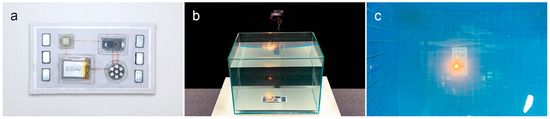
Figure 12.
(a) Paper interface for waterproofing test; (b) 0.4 m depth water environment; and, (c) 1 m depth water environment.
In the 30 tests at a 0.4 m depth, all of the circuits continued to work after half an hour and worked fine during the next 4.5 h. At a 1 m depth, 29 circuits continued to work after half an hour and they were not flooded for the next 4.5 h, with the circuits working normally. One interface failed, and the LED went out nearly six minutes after the test began. After removing it, we found a broken slit in the crease layer, which was perhaps caused due to the quality of the waterproof paper itself or a fabrication error. Overall, the results showed that ElectroPaper has a stable waterproofing ability.
4.2. Foldability Test
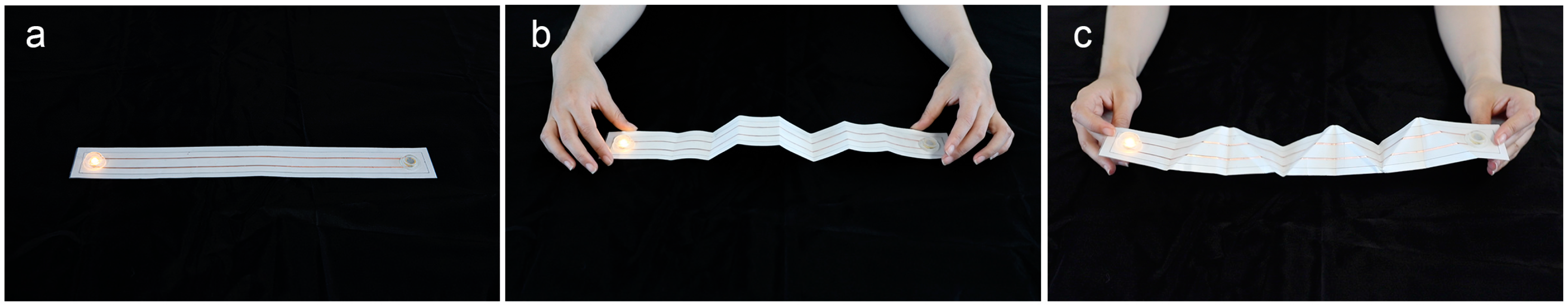
Foldability is an advantage of paper materials and the premise of papermaking technology. We tested ElectroPaper’s foldability by folding a paper-based electronic interface with a single electrical connection, which included a button battery and LED (Figure 13a). The paper interface was 42 cm × 5 cm, the battery and LED were at either end of the circuit, and the copper wire in the middle provided space for folding. We folded the paper interface in two ways: vertically (Figure 13b) and at a certain angle (Figure 13c). Each time, we folded the paper interface until it lacked folding space. We folded the circuit again along the previous crease on the opposite side to ensure that the circuits in the same position were folded multiple times.
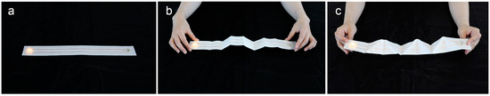
Figure 13.
(a) Paper interface for foldability test; (b) vertical folding; and, (c) tilted folding.
We carried out 30 tests each of vertical folding and tilted folding, and all of the folded circuits worked normally. We then placed the folded paper interfaces in a water environment with 1-m depth, and the circuits worked underwater for more than 30 minutes. The experimental results showed that the paper-based electronic interface has good foldability and it can work stably after multiple folds.
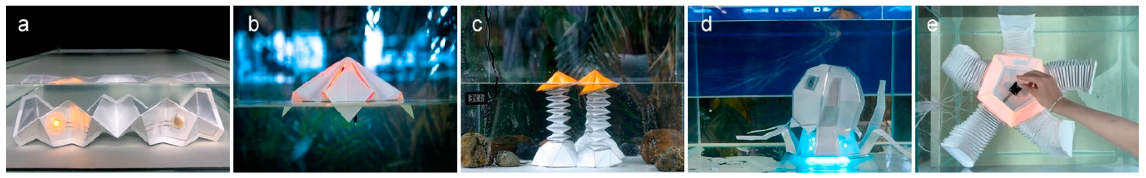
5. Example Application
Interaction occurring in a water environment is mainly influenced by the water environment, human, and device [42], presenting challenges to the design of prototypes for water environment use. ElectroPaper provides an integrated, highly functional design tool and fabrication method for electronic prototypes that were used in water environments. The system has a multilayer structure to ensure good folding capability and a waterproof effect. In order to evaluate the feasibility of this approach, we provide five electronic applications in a water environment, combining physical properties, such as water quality, temperature, depth, and buoyancy, to illustrate different water-based interactions and functions (e.g., environmental monitoring, underwater robots, entertainment, and decoration). They illustrate the advantages of paper as the medium for prototyping used in water environments, such as foldability (applications 5.1, 5.4), flexibility (5.3), and to be deployable (5.2, 5.5). The applications were created using our approach in shallow water (a depth less than 1 m).
5.1. Water Quality Detection
The total dissolved solids (TDS) measures the dissolved combined content of all inorganic and organic substances that are present in a liquid in molecular, ionized, or micro-granular (colloidal sol) suspended form [43]. The first application is a water quality detection device with a TDS sensor (Meter V1.0) (Sichuan, China) and two LEDs to monitor water quality in real time (Figure 14a). A higher value indicates more dissolved substances, i.e., poor water quality (Figure 14e). The LEDs will present a red light when the data exceed a set value (Figure 14c). In this application, all of the electronic components are placed on the bottom paper interface. Specifically, the probe of the TDS sensor penetrates the bottom paper interface to contact the water to detect water quality (Figure 1b). The paper structure at the top is hollow (Figure 14d), which requires the user to draw the outline of the hollow position on the surface when building the initial model. The 2D patterns also show the hollow-out traces.
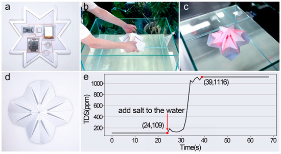
Figure 14.
Total dissolved solids (TDS) detection device: (a) Paper circuit; (b) placing device in water; (c) red light illuminates to alert when detected TDS values exceed a set value; (d) folded shape of device; (e) values detected by device.
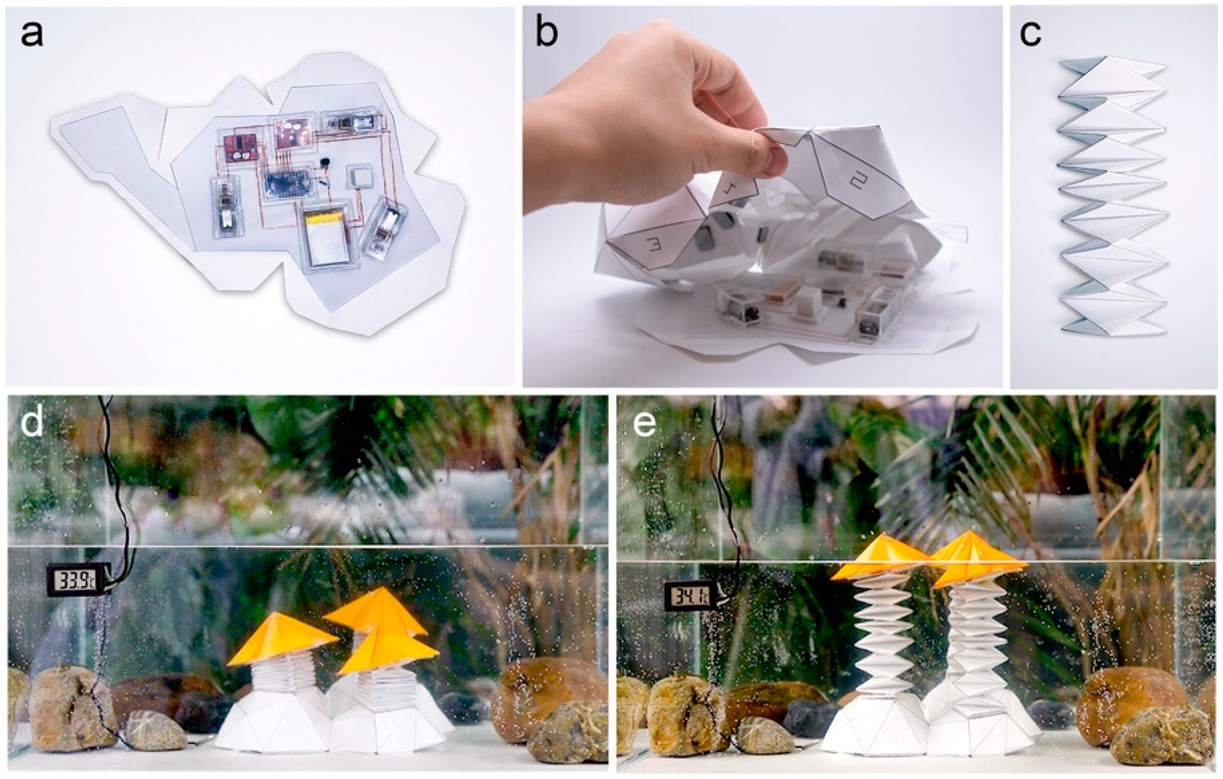
5.2. Water Temperature Sensing
An interactive decoration is designed for an outdoor shallow water environment, and it can react to a water temperature change. It comprises a microcontroller (ATmega32U4) (Guangdong, China), three DC motors (N20) (Guangdong, China), a battery (3.7 V, 1800 mAh) (Guangdong, China), a temperature sensor (DS18B20) (Guangdong, China), and two DC motor driver modules (L298N) (Guangdong, China), as shown in Figure 15a. We selected deployable structures from the component library and then connected them to three motors with three polyethylene (PE) threads (Figure 15c). A PE thread is wound around each motor’s drive shaft and then connected to the top of the deployable structure. With buoyancy, three star structures provide the power for the device to rise (Figure 15e). This application can efficiently switch between the tightened and released state. When the temperature sensor indicates that the water temperature is over 34 °C, the DC motors rotate clockwise to release the threads, and the star structures float to the surface as a result of their buoyancy (Figure 15e). In contrast, when the temperature falls below 34 °C, the DC motors rotate counterclockwise and the star structures start to drop under the strain of the threads (Figure 15d). In order to make the entire application sink, we defined the model’s working conditions in the software tool as “sink under water”, which let us know how many counterweights must be added to the paper interface (Figure 15b).
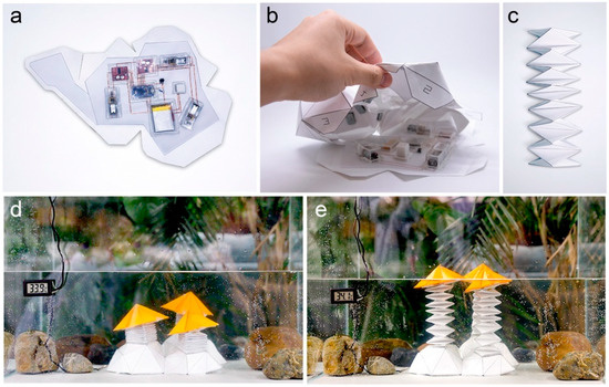
Figure 15.
Water temperature sensing. (a) Paper circuit; (b) inner part of folded Stone structure; (c) deployable paper structure; (d) the device sits at the bottom when the water temperature drops below 34 °C; and, (e) the device rises to the surface when the water temperature exceeds 34 °C.
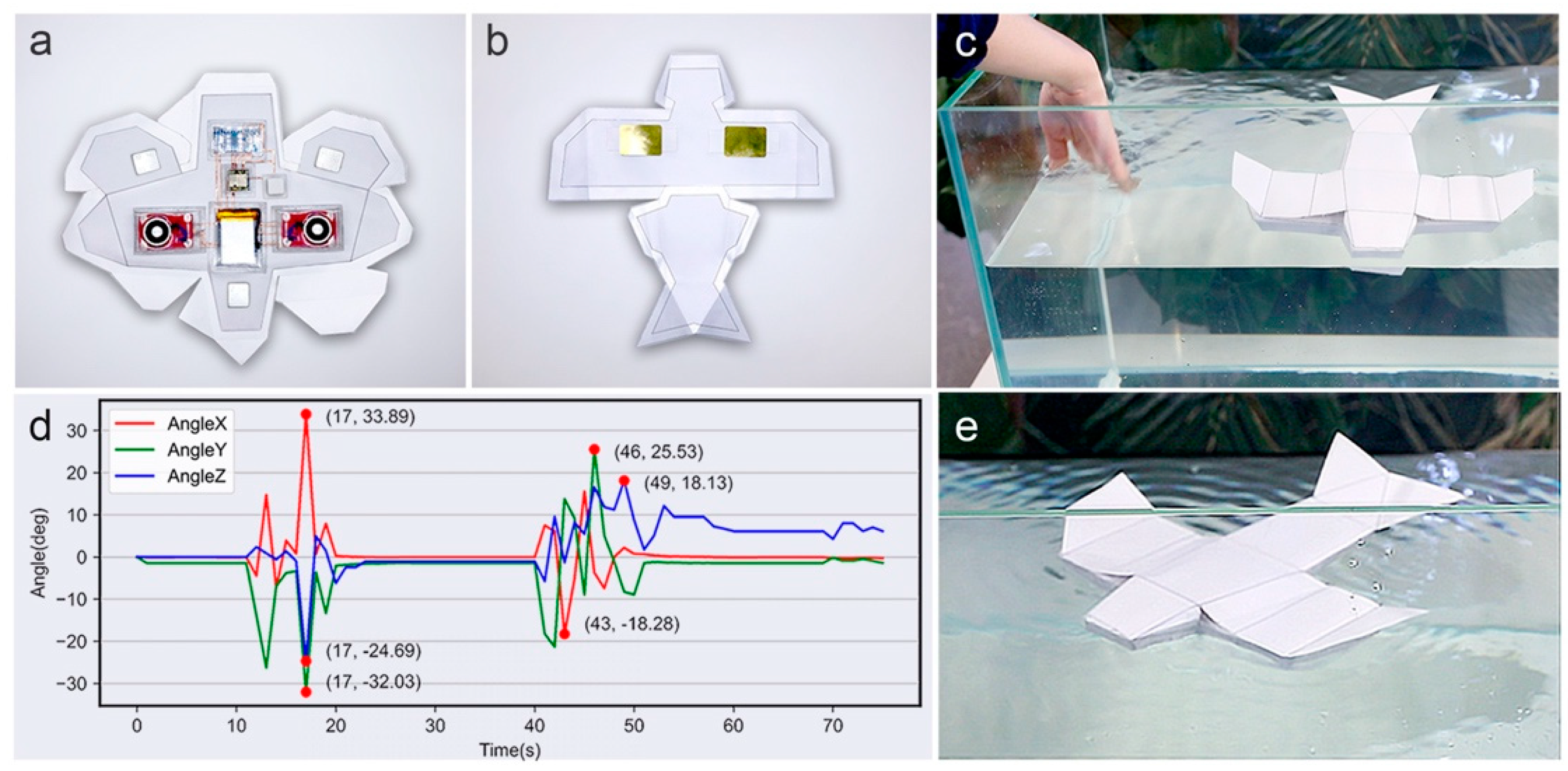
5.3. Water Wave Detection
Inspired by the flying fish, we used ElectroPaper to design a Fly Fish robot supporting an entertaining experience. The robot floats on still water in a dormant state; when the user slaps or disturbs the water (Figure 16c), it will vibrate the wings to create ripples (Figure 16e). In order to achieve this interaction, the Fly Fish robot contains a gyroscope (JY60) (Guangdong, China), a microcontroller (ATmega32U4) (Guangdong, China), and two suction-cup electromagnets (Guangdong, China) (Figure 16a). A thin piece of metal is glued on each wing. This metal piece can be attached by electromagnets (Figure 16b). The robot’s position changes as the user flaps the water surface. When the gyroscope detects a 15-degree angle change, the suction-cup electromagnet will continuously change its magnetism (Figure 16d), which will drive the flexible paper wings to vibrate and tap the water surface. The prototype must be balanced to float on the water, which can be analyzed by our design tool. The prototype has a sealed space to provide buoyancy, so it must be watertight.
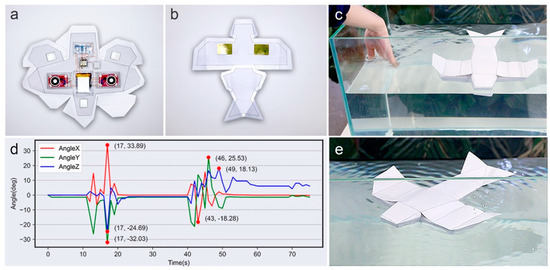
Figure 16.
Fly Fish robot: (a) paper circuit of robot; (b) thin pieces of metal are stuck to the wings and can be attracted by electromagnets; (c) the user flaps the water to interact with the robot; (d) data captured by gyroscope; and, (e) the robot vibrates its wings to create ripples.
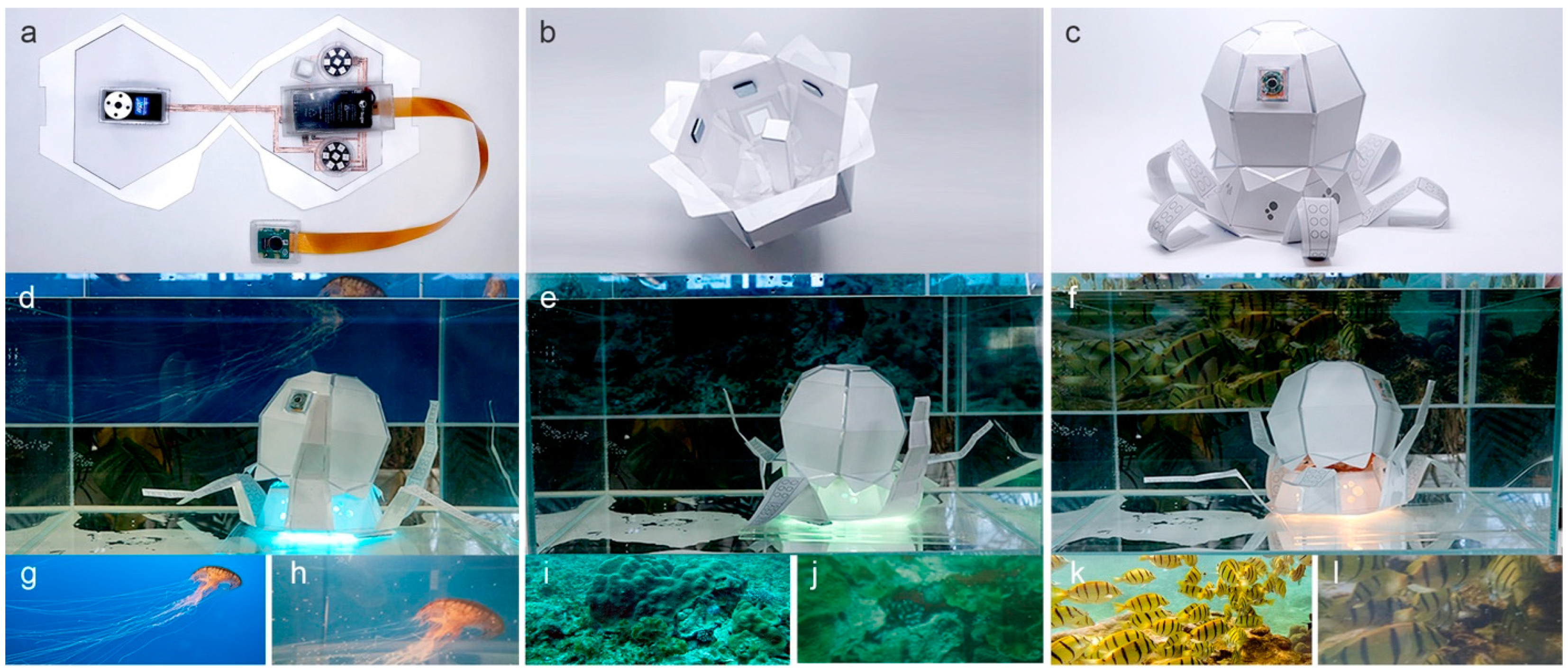
5.4. Camouflaged Underwater Camera
Underwater cameras help people to observe and understand the underwater world through photos or videos. The Octopus waterproof underwater camera shares the octopus’s color-changing and camouflage abilities. We used this device to explore the interaction between underwater devices and their surroundings. It can camouflage by emitting light of a recognized color (Figure 17d–f). The camera (Raspberry Pi Camera V2) (Cambridge, UK) is rotated by steering gear (SPT5425LV-W) (Guangdong, China) and it randomly captures anything in front of it, such as underwater topography and aquatic organisms (Figure 17h,j,l)). The program (Raspberry Pi), which is based on OpenCV, analyzes the data and determines the dominant color of the surroundings to adjust the RGB value of the LED. During fabrication, the users can fold the multilayer interface to shape or save space. The foldability of our paper-based electronic interface can ensure the correct signal transmission (Figure 17a). We selected a rigid structure (Figure 17b) from the component library to connect the robot’s head to the steering gear to rotate it. Like application 5.1, above, the robot needs to be hollowed out. The plasticity of paper allows users to design and cut different patterns into its surface, through which light can leak out (Figure 17c). This prototype works underwater, and counterweights are glued to the paper interface to increase gravity (Figure 17b).
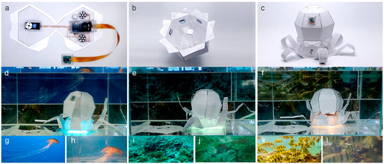
Figure 17.
Underwater camera: (a) paper circuit of Octopus; (b) folded paper prototype with a rigid structure and counterweights; (c) appearance of Octopus; (d–f): Octopus can recognize the color of its surroundings to change its body’s color; (g,i,k) are posters with different colors, placed on the outside of the tank; and, (h,j,l) are photos taken by the robot.
5.5. Deformation in Water
Inspired by soft underwater robots, Starfish was designed as a deformation robot. It floats and detects its surroundings in real time. When people touch it, it retracts five tentacles, darkens its body, and changes to the self-protection state to show fear (Figure 18d). When untouched, it will stretch out its tentacles to feel the environment. If safe, it will stretch out all of its tentacles and make its body glow to turn on an active state (Figure 18e). To help Starfish detect its surroundings, we folded the paper interface (Figure 18a), so that the infrared pyroelectric sensor (AM412) (Guangdong, China) faces the outside. Two RGB LED lights are used for lighting, and the battery, controller (ATmega32U4), communication module (NRF24L01, 2.4 GHz) (Guangdong, China), and voltage regulator module (AMS1117) (Guangdong, China) are arranged on the paper interface. Starfish can also interact with people through a wristband (Figure 18f) [42]. The wristband can capture the user’s hand movements through the internal battery (9 V), Bluetooth module, Arduino Pro Mini, and MPU-6050 (Guangdong, China) (Figure 18c) [42]. After receiving the data, Starfish “dances” in the water according to the user’s hand movements. It stretches tentacles when the user raises the arm and then retracts tentacles when the arm is dropped. Five sets of actuators, air pumps (kjh-370-br) (Guangdong, China), and airbags are placed out of the water. The stretchable tentacles can expand and contract through built-in airbags (Figure 18b). The initial models of the tentacles came from the component library of our design tool. We used this paper deployable model and parameterized it to simplify the modeling process. The middle part of the prototype must be waterproof to allow it to float.
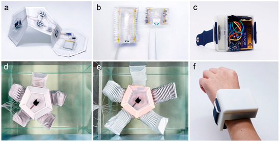
Figure 18.
Starfish: (a) folded paper circuit; (b) deployable structure with airbag; (c) internal structure of the wristband; (d) in the self-protection state, the robot retracts its tentacles and darkens its body; (e) in the active state, the robot stretches its tentacles and lightens its body; and, (f) wristband for users to interact with the Starfish.
6. Discussion and Limitations
ElectroPaper simplifies the fabrication of prototypes for water environment use in a low-cost way. This process was previously expensive, and prototypes were complex to fabricate. When compared to traditional methods, this approach can systematically and stably ensure the regular operation of electronic components in water, and it allows the consideration of electronic design in the modeling stage, such as the use of electronic components and circuit drawing. Balance assessment and buoyancy analysis improve the usefulness of the prototype and help users to reduce iteration times. However, this approach also has disadvantages. When compared with 3D printing, a common prototyping method contains more manual work, such as folding, waterproof shell making, and each step needs to be carefully made. Moreover, it needs more auxiliary materials, such as paper, waterproof glue, and conductive glue, which are low-cost but essential.
We use synthetic materials (PET, BOPP, OPP) as substrates and define them as paper. All of these materials are low-cost commercial products that are easy to fold. Specifically, the papers have a good waterproof effect. However, the materials are off the shelf, and their quality might inject uncertainty into the fabrication effect. The adhesion between layers mainly depends on the glue on the first layer. We apply waterproof glue to the edge of the paper interface in order to increase the waterproof effect.
We customized waterproof shells for electronic components. The waterproof epoxy shell can be easily installed, used repeatedly, and simply processed, and the materials are low-cost and easily available, but it still has deficiencies. The component’s shape and size determine the design of the waterproof shell. That means that the shells are not universal for all components. The shell that is pasted on the paper interface is a solid, rigid geometric structure, and it cannot be arranged on the crease. According to our test, the crease’s limit position is the waterproof shell’s edge. In the future, we will improve the foldability of paper circuits by adding foldable, flexible printed circuit boards, and using soft waterproof shells.
We refer to origami-related algorithms [7] to expand 3D objects into 2D planes and generate creases and flaps. The current algorithm has limitations. It requires the 3D model to be intact, without hollow-out surfaces, somewhat limiting the user’s modeling. For this reason, the user needs to patch the hollow-out surfaces before unfolding the 3D model. Additionally, the initial model requires a flat surface if the user intends to place electronics on it. The placement of the electronic components requires manual adjustment. The size of the model is influenced by the size of the components. The user must consider all of these things when building a model, so as to expedite the fabrication process. Although there are geometric limitations, these do not affect the fabrication process or the prototype’s presentation.
We set the waterproof test time of five hours based on the waterproof effect of the material itself, the working time of electronic components (such as batteries), and the prototype test time. We believe that five hours of underwater testing time is sufficient for most of the prototypes. Our goal is to provide an approach for underwater prototyping that may not have as long an underwater duration as a mature product. For some special applications that require a long testing time, we think that this can be achieved by successive use of multiple identical prototypes. Based on our experience testing waterproofing materials, if a system is not waterproof, then water will enter it in a short time, and much faster in 1 m of water. In particular, there is little randomness in the waterproofing test, so we set up 30 groups, and we believe that this is sufficient to show that our fabrication method has a stable waterproofing effect.
7. Conclusions
We presented ElectroPaper, a low-cost and effective fabrication approach for simplifying the creation of electronic prototypes that are used in water environments, with a paper-based electronic interface to achieve high functionality. The structure integrates a crease layer, hardware distribution layer, and hollow-out layer to enhance the waterproofing and foldability. ElectroPaper includes a design tool with the functions of balance analysis, 3D model unfolding, and circuit drawing, which empowers individuals to create prototypes of devices for water environment use. This approach embraces affordable paper circuits for water environments and offers new possibilities for papercraft techniques. We designed five devices using this approach, demonstrating the integration of different electronics in the paper-based interface and their use in water. Application examples and evaluations verified the effectiveness and universality of this approach, as well as its waterproofing and foldability. Our work allows researchers to focus on the water environment, which supports the creation of prototypes to explore it.
Author Contributions
Conceptualization, methodology, formal analysis, validation, and writing—original draft preparation, L.L.; resources and writing—review and editing, J.G.; software, C.Z.; Z.W.; P.Z.; hardware, T.F.; J.W.; supervision, C.Y.; F.Y. All authors have read and agreed to the published version of the manuscript.
Funding
This research was funded by the Engineering Research Center of Computer Aided Product Innovation Design, Ministry of Education, Fundamental Research Funds for the Central Universities, National Natural Science Foundation of China, grant number 52075478, Major Project of Zhejiang Social Science Foundation, grant number 21XXJC01ZD.
Data Availability Statement
No new data were created or analyzed in this study. Data sharing is not applicable to this article.
Conflicts of Interest
The authors declare no conflict of interest.
References
- Qi, J.; Buechley, L. Electronic Popables: Exploring paper-based computing through an interactive pop-up book. In Proceedings of the Fourth International Conference on Tangible, Embedded, and Embodied Interaction (TEI’10), Cambridge, MA, USA, 25–27 January 2010; pp. 121–128. [Google Scholar]
- Qi, J.; Buechley, L. Sketching in circuits: Designing and building electronics on paper. In Proceedings of the SIGCHI Conference on Human Factors in Computing Systems (CHI’14), Toronto, ON, Canada, 26 April 2014; pp. 1713–1722. [Google Scholar]
- Wang, G.Y.; Cheng, T.Y.; Do, Y.W.; Yang, H.; Tao, Y.; Gu, J.Z.; An, B.; Yao, L.N. Printed paper actuator: A low-cost reversible actuation and sensing method for shape changing interfaces. In Proceedings of the 2018 CHI Conference on Human Factors in Computing Systems (CHI’18), Montreal, QC, Canada, 21–26 April 2018; pp. 1–12. [Google Scholar]
- Schulz, A.; Sung, C.; Spielberg, A.; Zhao, W.; Cheng, R.; Grinspun, E.; Rus, D.; Matusik, W. Interactive robogami: An end-to-end system for design of robots with ground locomotion. Int. J. Robot. Res. 2017, 36, 1131–1147. [Google Scholar] [CrossRef]
- Zheng, C.; Gyory, P.; Do, E.Y. Tangible interfaces with printed paper markers. In Proceedings of the 2020 ACM on Designing Interactive Systems Conference, Eindhoven, The Netherlands, 6–20 July 2020; pp. 909–923. [Google Scholar]
- Zhu, K.N.; Zhao, S.D. AutoGami: A low-cost rapid prototyping toolkit for automated movable paper craft. In Proceedings of the SIGCHI Conference on Human Factors in Computing Systems, Paris, France, 27–28 April 2013; pp. 661–670. [Google Scholar]
- Haenselmann, T.; Effelsberg, W. Optimal strategies for creating paper models from 3D objects. Multimed. Syst. 2012, 18, 519–532. [Google Scholar] [CrossRef]
- Oppermann, L.; Blum, L.; Shekow, M. Playing on AREEF: Evaluation of an underwater augmented reality game for kids. In Proceedings of the 18th International Conference on Human-Computer Interaction with Mobile Devices and Services (MobileHCI’16), Florence, Italy, 6–9 September 2016; pp. 330–340. [Google Scholar]
- Yamashita, S.; Zhang, X.L.; Rekimoto, J. AquaCAVE: Augmented swimming environment with immersive surround-screen virtual reality. In Proceedings of the 29th Annual Symposium on User Interface Software and Technology (UIST’16 Adjunct), Tokyo, Japan, 16–19 October 2016; pp. 183–184. [Google Scholar]
- Pell, S.J.; Mueller, F. Gravity Well: Underwater play. In Proceedings of the Extended Abstracts of the 2020 CHI Conference on Human Factors in Computing Systems (CHI EA’13), Paris, France, 27–28 April 2013; pp. 3115–3118. [Google Scholar]
- Choi, W.; Oh, J.; Park, T.; Kang, S.J.; Moon, M.; Lee, U.; Hwang, I.; Song, J. MobyDick: An interactive multi-swimmer exergame. In Proceedings of the 12th ACM Conference on Embedded Network Sensor Systems (SenSys’14), Memphis, TN, USA, 3–6 November 2014; pp. 76–90. [Google Scholar]
- Koike, H.; Matoba, Y.; Takahashi, Y. AquaTop Display: Interactive water surface for viewing and manipulating information in a bathroom. In Proceedings of the 2013 ACM International Conference on Interactive Tabletops and Surfaces (ITS’13), Andrews, UK, 6–9 October 2013; pp. 155–164. [Google Scholar]
- Matoba, Y.; Takahashi, Y.; Tokui, T.; Phuong, S.; Yamano, S.; Koike, H. AquaTop Display: A true “Immersive” water display system. In Proceedings of the ACM SIGGRAPH 2013 Emerging Technologies (SIGGRAPH’13), Anaheim, CA, USA, 21–25 July 2013; p. 1. [Google Scholar]
- Pell, S.J. Aquabatics: A post-turbulent performance in water. Perform. Res. 2014, 19, 98–108. [Google Scholar] [CrossRef]
- Watanabe, J.I. VortexBath: Study of tangible interaction with water in bathroom for accessing and playing media files. In Proceedings of the 12th International Conference on Human-Computer Interaction: Interaction Platforms and Techniques (HCI’07), Beijing, China, 22–27 July 2007; pp. 1240–1248. [Google Scholar]
- Ukai, Y.; Rekimoto, J. Swimoid: A swim support system using an underwater buddy robot. In Proceedings of the 4th Augmented Human International Conference (AH’13), Stuttgart, Germany, 7–8 March 2013; pp. 170–177. [Google Scholar]
- Chutia, S.; Kakoty, N.M.; Deka, D. A review of underwater robotics, navigation, sensing techniques and applications. In Proceedings of the Advances in Robotics (AIR’17), New Delhi, India, 28 June–2 July 2017; pp. 170–177. [Google Scholar]
- Raffe, W.L.; Tamassia, M.; Zambetta, F.; Li, X.D.; Pell, S.J.; Mueller, F.F. Player-computer interaction features for designing digital play experiences across six degrees of water contact. In Proceedings of the 2015 Annual Symposium on Computer-Human Interaction in Play (CHI PLAY’15), London, UK, 4–7 October 2015; pp. 295–305. [Google Scholar]
- Saul, G.; Xu, C.; Gross, M.D. Interactive paper devices: End-user design & fabrication. In Proceedings of the Fourth International Conference on Tangible, Embedded, and Embodied Interaction (TEI’10), Cambridge, MA, USA, 25–27 January 2010; pp. 205–212. [Google Scholar]
- Oh, H.J. From papercraft to paper mechatronics: Exploring a new medium and developing a computational design tool. In Proceedings of the 28th Annual ACM Symposium on User Interface Software & Technology (UIST’15 Adjunct), Charlotte, NC, USA, 8–11 November 2015; pp. 17–20. [Google Scholar]
- Fuchs, A.; Sturdee, M.; Schöning, J. Foldwatch: Using origami-inspired paper prototypes to explore the extension of output space in smartwatches. In Proceedings of the 10th Nordic Conference on Human-Computer Interaction (NordiCHI’18), Oslo, Norway, 29 September–3 October 2018; pp. 47–59. [Google Scholar]
- Chang, Z.; Ta, T.D.; Narumi, K.; Kim, H.; Okuya, F.; Li, D.C.; Kato, K.; Qi, J.; Miyamoto, Y.; Saito, K.; et al. Kirigami haptic swatches: Design methods for cut-and-fold haptic feedback mechanisms. In Proceedings of the 2020 CHI Conference on Human Factors in Computing Systems (CHI’20), Honolulu, HI, USA, 25–30 April 2020; pp. 1–12. [Google Scholar]
- Nakahara, K.; Narumi, K.; Niiyama, R.; Kawahara, Y. Electric phase-change actuator with inkjet printed flexible circuit for printable and integrated robot prototyping. In Proceedings of the 2017 IEEE International Conference on Robotics and Automation (ICRA), Singapore, 29 May–3 June 2017; pp. 1856–1863. [Google Scholar]
- Shorter, M.; Rogers, J.; McGhee, J. Enhancing everyday paper interactions with paper circuits. In Proceedings of the 2014 Conference on Designing Interactive Systems (DIS’14), Vancouver, BC, Canada, 21–25 June 2014; pp. 39–42. [Google Scholar]
- Mellis, D.A.; Jacoby, S.; Buechley, L.; Wilson, H.P.; Qi, J. Microcontrollers as material: Crafting circuits with paper, conductive ink, electronic components, and an “Untoolkit”. In Proceedings of the 7th International Conference on Tangible, Embedded and Embodied Interaction (TEI’13), Barcelona, Spain, 10–13 February 2013; pp. 83–90. [Google Scholar]
- Oh, H.J.; Eisenberg, M.; Gross, M.D.; His, S. Paper Mechatronics: A design case study for a young medium. In Proceedings of the 14th International Conference on Interaction Design and Children (IDC’15), Boston, MA, USA, 21–24 June 2015; pp. 371–374. [Google Scholar]
- Oh, H.J.; Hsi, S.; Klipfel, K.; Gross, M.D. Paper machines. In Proceedings of the Eleventh International Conference on Tangible, Embedded, and Embodied Interaction (TEI’17), Yokohama, Japan, 20–23 March 2017; pp. 771–774. [Google Scholar]
- Qi, J.; Buechley, L. Animating paper using shape memory alloys. In Proceedings of the SIGCHI Conference on Human Factors in Computing Systems (CHI’12), Austin, TX, USA, 5–10 May 2012; pp. 749–752. [Google Scholar]
- Koizumi, N.; Yasu, K.; Liu, A.; Sugimoto, M.; Inami, M. Animated Paper: A toolkit for building moving toys. Comput. Entertain. 2010, 8, 1–16. [Google Scholar] [CrossRef]
- Rus, D.; Tolley, M.T. Design, fabrication and control of origami robots. Nat. Rev. Mater. 2018, 3, 101–112. [Google Scholar] [CrossRef]
- Lang, R.J. A computational algorithm for origami design. In Proceedings of the Twelfth Annual Symposium on Computational Geometry, Philadelphia, PA, USA, 1 May 1996; pp. 98–105. [Google Scholar]
- Lang, R.J. Origami 4; Peters, A.K., Ed.; CRC Press: New York, NY, USA, 2009; pp. 1–572. [Google Scholar]
- Mitani, J.; Suzuki, H. Making papercraft toys from meshes using strip-based approximate unfolding. ACM Trans. Graph 2004, 23, 259–263. [Google Scholar] [CrossRef]
- Chang, Z.K.; Ta, T.D.; Narumi, K.; Kim, H.; Okuya, F.; Li, D.C.; Kato, K.; Qi, J.; Miyamoto, Y.; Saito, K.; et al. Demonstrating Kirigami haptic swatches for cut-and-fold haptic feedback mechanisms. In Proceedings of the 2020 CHI Conference on Human Factors in Computing Systems (CHI EA’20), Honolulu, HI, USA, 25–30 April 2020; pp. 1–4. [Google Scholar]
- Eisenberg, M.; Nishioka, A. Creating polyhedral models by computer. J. Comput. Math. Sci. Teach. 1997, 16, 477. [Google Scholar]
- Gong, J.T.; Wang, J.; Xu, Y.Q. PaperLego: Component-based papercraft designing tool for children. In Proceedings of the SIGGRAPH Asia 2014 Designing Tools for Crafting Interactive Artifacts (SA’14), Shenzhen, China, 3–6 December 2014; pp. 1–4. [Google Scholar]
- Zhu, K.N.; Deshan, C.; Fernando, O.N.N. Snap-n-Fold: Origami pattern generation based real-life object structure. In Proceedings of the Extended Abstracts of the 2012 CHI Conference on Human Factors in Computing Systems (CHI EA’12), Austin, TX, USA, 5–10 May 2012; pp. 2345–2350. [Google Scholar]
- Oh, Y.J.; Kim, J.; Morales, C.; Gross, M.; Eisenberg, M.; His, S. FoldMecha: Exploratory design and engineering of mechanical papercraft. In Proceedings of the Eleventh International Conference on Tangible, Embedded, and Embodied Interaction (TEI’17), Yokohama, Japan, 20–23 March 2017; pp. 131–139. [Google Scholar]
- Markvicka, E.; Wang, G.Y.; Lee, Y.C.; Laput, G.; Majidi, C.; Yao, L.N. ElectroDermis: Fully untethered, stretchable, and highly-customizable electronic bandages. In Proceedings of the 2019 CHI Conference on Human Factors in Computing Systems (CHI’19), Glasgow, UK, 4–9 May 2019; pp. 1–10. [Google Scholar]
- International Electrotechnical Commission. Degrees of Protection Provided by Enclosures (IP Code); International Electrotechnical Commission, Swiss Confederation: Geneva, Switzerland, 2013. [Google Scholar]
- International Protection (IP)—EN 60529. Available online: http://www.uni-valve.com/files/pdf/teknik/ip.pdf (accessed on 5 August 2020).
- Liu, L.J.; Yao, C.; Lin, Y.Y.; Chen, Y.; Liu, Z.Y.; Ying, F.T. AquaBot: An interactive system for digital water play. In Proceedings of the International Conference on Human-Computer Interaction, Orlando, FL, USA, 26–31 July 2019; pp. 16–27. [Google Scholar]
- Rhoades, J.D. Salinity: Electrical Conductivity and Total Dissolved Solids. In Methods of Soil Analysis; Sparks, D.L., Page, A.L., Eds.; The Soil Science Society of America: Madison, WI, USA, 1996; pp. 417–435. ISBN 978-0-89118-866-7. [Google Scholar]


Publisher’s Note: MDPI stays neutral with regard to jurisdictional claims in published maps and institutional affiliations. |
© 2021 by the authors. Licensee MDPI, Basel, Switzerland. This article is an open access article distributed under the terms and conditions of the Creative Commons Attribution (CC BY) license (http://creativecommons.org/licenses/by/4.0/).