Article

On Multi-Scalar Multiplication Algorithms for Register-Constrained Environments

1
China Tianjin Key Laboratory of Advanced Networking (TANK), College of Intelligence and Computing, Tianjin University, Tianjin 300350, China
2
Department of Computer Science and Engineering, Tongji University, No. 1239 Siping Road, Hongkou District, Shanghai 201804, China
*
Author to whom correspondence should be addressed.
Electronics 2021, 10(5), 605; https://doi.org/10.3390/electronics10050605
Submission received: 28 December 2020 / Revised: 22 February 2021 / Accepted: 27 February 2021 / Published: 5 March 2021
(This article belongs to the Special Issue Hardware Support for the Security of Computing Devices)

Abstract

:
A basic but expensive operation in the implementations of several famous public-key cryptosystems is the computation of the multi-scalar multiplication in a certain finite additive group defined by an elliptic curve. We propose an adaptive window method for the multi-scalar multiplication, which aims to balance the computation cost and the memory cost under register-constrained environments. That is, our method can maximize the computation efficiency of multi-scalar multiplication according to any small, fixed number of registers provided by electronic devices. We further demonstrate that our method is efficient when five registers are available. Our method is further studied in detail in the case where it is combined with the non-adjacent form (NAF) representation and the joint sparse form (JSF) representation. One efficiency result is that our method with the proposed improved NAF n -bit representation on average requires 209n/432 point additions. To the best of our knowledge, this efficiency result is optimal compared with those of similar methods using five registers. Unlike the previous window methods, which store all possible values in the window, our method stores those with comparatively high probabilities to reduce the number of required registers.

1. Introduction

The notations in Table 1 are used throughout this paper, often without further definition. Others are defined where they are first used and in Appendix A.
A basic but expensive operation in the implementations of several famous public-key schemes, for instance, Digital Signature Algorithm (DSA) [1], Elliptic Curve Digital Signature Algorithm (ECDSA) [2], and the Schnorr signature scheme [3], is the computation of the multi-scalar multiplication in a certain finite additive group defined by an elliptic curve or the multi-exponentiation in a certain finite multiplication group. Moreover, many public-key protocols, such as [4,5,6,7], also require one or more of the multi-scalar multiplication/multi-exponentiation operations.
For a better understanding of this, we adopt the symbol system of the multi-scalar multiplication herein. Without loss of generality, all techniques discussed in this paper can also be directly applied to the computation of the multi-exponentiation. The multi-scalar multiplication can be written as follows: given two integers x and y , and points   A E ( F q ) and B E ( F q ) , compute x A + y B . Due to the large operands, the computation of the multi-scalar multiplication requires a large number of processing steps and is thus time consuming. Since cryptographic implementations on embedded devices provided with little computation and memory power are often desired, a challenging problem is how to reduce the costs for the computation of the multi-scalar multiplication.

1.1. Previous Work

Obviously, we can separately compute the scalar multiplication values x A and y B , and then add them together. Gordon [8] surveyed the key techniques for the computation of the scalar multiplication. However, since the public-key cryptosystems do not require the intermediate values x A and y B , Shamir [9] suggested a simple but efficient trick for speeding up the multi-scalar multiplication by doing the two scalar multiplications simultaneously. Figure 1, describes Algorithm Shamir’s trick. Indeed, start from C O in Step 2. In Step 3, scan the bit pair of ( x i y i ) for i = n 1 ,   n 2 , , 1 simultaneously from left to right. In Step 3.1, always do   C 2 C and it means that this step requires n 1 point doublings. Then, if the current bit pair of ( x i y i ) are ( 1 0 ) , ( 0 1 ) , or ( 1 1 ) , add by A , B , or A + B in Step 3.2 accordingly. For example, to compute 51 A + 169 B , write the binary expansion of 51 and 169 as 51 = ( 00110011 ) 2 and 169 = ( 10101001 ) 2 and apply the rules above so that the successive values of C are at each step O , B , 2 B , A + 5 B , 3 A + 10 B , 6 A + 21 B , 12 A + 42 B , 25 A + 84 B , and finally 51 A + 169 B .
It needs to be pointed out that more sophisticated techniques can potentially improve Step 3.2 to reduce the number of point additions. The value w ( n ) is equal to the number of bit pairs ( x i y i ) , in which at least one bit, i.e., x i or y i , is nonzero. It therefore implies that the performance factor is
w S T ( n ) = 3 n 4
on average.
Based on the frame of Shamir’s trick, the improved multi-scalar multiplication algorithms are divided into two categories. The first category codes the integers x and y so that the number of zero bit pairs, i.e.,   ( x i y i ) = ( 0 0 ) , increases. Whereas the binary representation for an integer is unique, the signed binary representation by 1 , 1 , and 0 is not. Since the cost of computing the inverse of a point is negligible compared to the point addition over the elliptic curve group, the improved multi-scalar multiplication algorithms, detailed in [10,11,12,13,14,15,16,17], require only one extra register to store the value A   B in Step 1 of Algorithm Shamir’s trick in Figure 1. The NAF representation [18,19] is optimal for one integer. The performance factor w N A F 4 ( n ) can be improved to 5 n / 9 on average, when the algorithm uses the NAF representation instead. The JSF [11] is the optimal signed binary representation for two integers. The performance factor w J S F 4 ( n ) can further hit n / 2 on average, when the algorithm uses the JSF representation instead. Due to its optimality property, a disadvantage of the coding approach is that the best performance factor cannot exceed the value wJSF−4(n). The second category, in contrast, scans and processes the w -bit pair in Step 3.2 of Algorithm Shamir’s trick in Figure 1, where w is an integer, and w > 1 . To reduce the number of point additions, all possible values for w -bit pairs should be pre-computed and stored in Step 1 of Algorithm Shamir’s trick in Figure 1. Certainly, the wide scanning approach [20,21,22,23,24,25], including the m -ary method and the sliding window method, always combines with the coding approach, such as the NAF representation and the JSF representation, in practice. However, the approach requires a large number of extra registers to store all possible values for w -bit pairs, even with a moderate w .
Finally, some works [26,27] are dedicated to presenting the parallel algorithms for the multi-scalar multiplication, because the chip manufacturers are increasing the number of cores inside the processors. Other works [28,29] focus on the algorithms to speed up a group of the multi-scalar multiplications under cryptosystem configurations.

1.2. Motivation and Contribution

As low-cost computing devices, such as smartcards and RFID tags, are becoming ever more pervasive, new security threats are growing very quickly. However, these devices cannot always provide enough computation, memory, and electric power resources to implement the standard public-key schemes. We give several examples of potential crypto-oriented devices under register-constrained environments. One example is the ATmega128, which is part of the megaAVR family from Atmel [30] and has been widely used in embedded systems, automotive environments, and sensor-node applications. The ATmega128 features 128 KB of flash memory and 4 KB of internal SRAM. Additionally, it has only 32 8 -bit general-purpose registers (R0 to R31) and the 16 -bit result is stored in the registers R0 (lower word) and R1 (higher word). Another example is the ARM7TDMI (ARM7 Thumb Debug Multiplier ICE) [31], which was introduced by ARM in 1994 and has been used in a wide range of applications, e.g., mobile devices produced by Nokia and Motorola, Apple’s iPod, video game consoles integrated by companies such as SEGA and Sony, routers, and automobile systems. For the standard ARM operating mode, 16 general-purpose registers (R0 to R15) are available to users. In the Thumb mode, only eight registers are available, i.e., R0 to R7, which in general limits the applicability for many cryptographic algorithms. Moreover, even if these devices will be more powerful as a result of Moore’s Law, the manufacturer may still prefer those that are less powerful but more cost competitive. As a result, cryptographic engineers are always faced with a situation where the number of available registers is not sufficient for the ideal cryptographic implementation of multi-scalar multiplication.
Therefore, under register-constrained environments, this paper focuses on the design and analysis of the multi-scalar multiplication algorithms, which can flexibly improve the computation efficiency based on the available registers. We present an adaptive window method, which codes the integers x and y in the forms such as the NAF. Our adaptive window method can practically improve the computation efficiency of multi-scalar multiplication according to the small, fixed number of the registers provided by the register-constrained computing devices. To illustrate this, we further give an example with five registers. To be more precise, we consider the 5-register adaptive window method using the NAF and JSF, respectively. Additionally, the computational complexity is analyzed by modeling the scan process as the Markov chain. Furthermore, the performance factor for the adaptive window method using our improved NAF representation can achieve
w I N A F 5 ( n ) = 209 n 432   ,
on average, which is slightly smaller than using the JSF representation. To the best of our knowledge, when only five registers are allowed, our method with the improved NAF representation is the most efficient one for the computation of the multi-scalar multiplication.

2. Adaptive Window Method

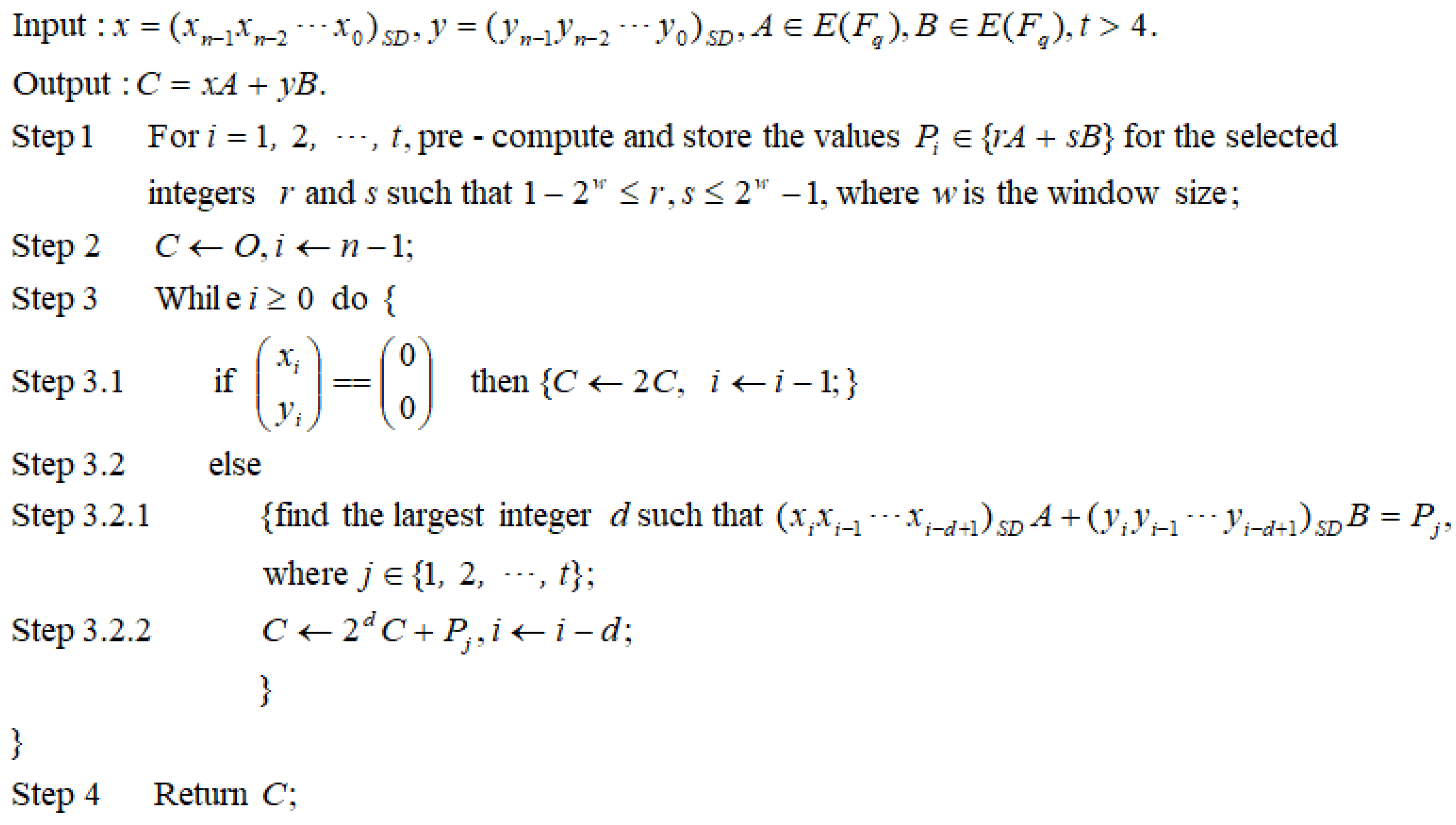
Assume that the register-constrained computing devices can provide t registers for the computation of multi-scalar multiplication. Figure 2 describes the Algorithm adaptive window method. The integers x and y are coded by a certain signed binary representation, i.e.,
x = i = 0 n 1 x i 2 i = ( x n 1 x n 2 x 0 ) S D
and
y = i = 0 n 1 y i 2 i = ( y n 1 y n 2 y 0 ) S D ,
where x i , y i { 1 ,   1 ,   0 } . Let w denote the window size. In Step 3 of Algorithm Adaptive window method in Figure 2, scan x and y in the ordinary signed binary representations from left to right for the largest bit(s) pair within the window such that the pair has a value already precomputed in Step 1 and its first 1-bit sub-pair is nonzero.
To compute the multi-scalar multiplication, previous window methods require to store all possible values for w -bit pairs. However, our adaptive window method merely pre-computes and stores part of the values for these pairs (See Step 1 of Algorithm Adaptive window method in Figure 2), when the available registers (whose number is denoted by t ) are not enough. Thus, our method may spend more than one point addition for w -bit pairs using Steps 3.1 and 3.2 of Algorithm Adaptive window method in Figure 2. Obviously, to reduce the number of point additions as much as possible, Step 1 of Algorithm Adaptive window method in Figure 2 should select the pairs with comparatively high probabilities in the signed sequence pair ( x n 1 x n 2 x 0 y n 1 y n 2 y 0 ) and store their corresponding values. As a result, the achievement of our adaptive window method is that the computation efficiency of the multi-scalar multiplication can be flexibly improved according to the registers provided by the register-constrained computing devices. Comparatively, previous window methods require the fixed number of registers based on the window size w .
Compared with Shamir’s trick using the NAF representation or the JSF representation, algorithm Adaptive window method in Figure 2 at least requires five registers to improve the computation efficiency of the multi-scalar multiplication. Therefore, in the next section, we provide an example of the adaptive window method. That is, a detailed design and analysis for t = 5 is presented with the NAF representation and the JSF representation, respectively.

3. A Case Study: Adaptive Window Method for Five Registers

3.1. Using NAF Representation

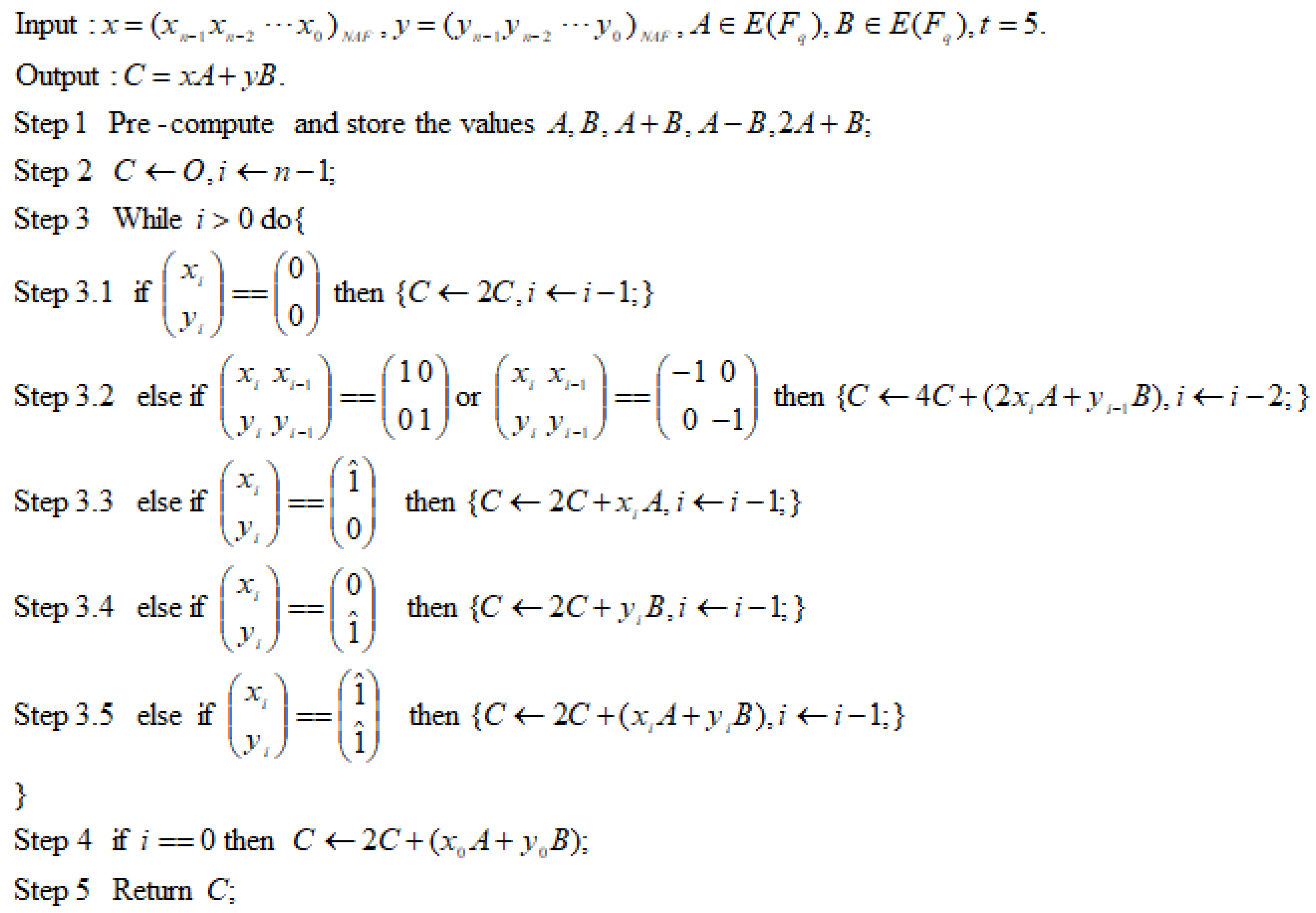
Algorithm The 5-register algorithm using the non-adjacent form (NAF) representation in Figure 3 illustrates the basic version of the adaptive window method combined with the NAF representation, when five registers are available. In this case, we find that the pairs ( 1 ^ 0 ) , ( 0 1 ^ ) , ( 1 ^ 1 ^ ) , ( 1 0 0 1 ) , and ( 1 0 0 1 ) have comparatively high probabilities in the NAF sequence pair ( x n 1 x n 2 x 0 y n 1 y n 2 y 0 ) on average. Hence, Step 1 of Algorithm The 5-register algorithm using the non-adjacent form (NAF) representation in Figure 3 correspondingly requires the values A , B , A + B , A B , and 2 A + B . Additionally, Step 3 scans and collects the pairs ( 1 ^ 0 ) , ( 0 1 ^ ) , ( 1 ^ 1 ^ ) , ( 1 0 0 1 ) , and ( 1 0 0 1 ) in the NAF sequence pair ( x n 1 x n 2 x 0 y n 1 y n 2 y 0 ) and then computes their corresponding values. For example, to compute 51 A + 169 B , write the NAF expansion of 51 and 169 as 51 = ( 010 1010 1 ) N A F and 169 = ( 10101001 ) N A F and apply the defined rules in Steps 1, 3.1, 3.2, 3.3, 3.4, 3.5, and 4 so that the successive values of C are at each step O, B , 2 A + 5 B , 3 A + 10 B ,   6 A + 21 B , 13A + 42B, 26 A + 84 B , and finally 51 A + 169 B .
Due to the frame of Shamir’s trick, the above 5 -register algorithm still requires n 1 point doublings. Thus, we only need to consider its performance factor, which directly determines the number of point additions. We have the following result.
Theorem 1.
The performance factor of Algorithm The 5-register algorithm using the non-adjacent form (NAF) representation in Figure 3 is
w B N A F 5 ( n ) = n 2
on average, when n .
The proof of Theorem 1 appears in Appendix B and Appendix C.
According to Theorem 1, the basic version of the above 5 -register algorithm has the same performance factor as that of Shamir’s trick coupled with the JSF representation, which merely needs four registers. However, the basic version can be further improved to reduce its performance factor. We propose the recoding rules for the input NAF sequence pair ( x n 1 x n 2 x 0 y n 1 y n 2 y 0 ) as follows:
Rule   A 1 .   ( 1 0 1 0 1 0 ) ( 0 1 1 0 1 0 ) ;   Rule   A 2 .   ( 1 0 1 0 1 0 ) ( 0 1 1 0 1 0 ) ; Rule   A 3 .   ( 0 1 0 1 0 1 ) ( 0 1 0 0 1 1 ) ; Rule   A 4 .   ( 0 1 0 1 0 1 ) ( 0 1 0 0 1 1 ) ; Rule   A 5 .   ( 1 0 1 0 0 0 0 1 ) ( 0 1 1 0 0 0 0 1 ) ; Rule   A 6 .   ( 1 0 1 0 0 0 0 1 ) ( 0 1 1 0 0 0 0 1 ) ; Rule   A 7 .   ( 1 0 1 0 0 1 0 1 ) ( 0 1 1 0 0 1 0 1 ) ; Rule   A 8 .   ( 1 0 1 0 0 1 0 1 ) ( 0 1 1 0 0 1 0 1 ) .
After Step 1 of Algorithm The 5-register algorithm using the non-adjacent form (NAF) representation in Figure 3, the improved 5 -register algorithm converts ( x n 1 x n 2 x 0 y n 1 y n 2 y 0 ) into ( x n 1 x n 2 x 0 y n 1 y n 2 y 0 ) by replacing according to the above recoding rules from left to right. If the replacement is due to Rule A1, A2, A3, or A4, then discard the left two columns that have been replaced and consider the next three or four columns for future replacement. If a replacement is due to Rule A5, A6, A7, or A8, then discard all columns that have been replaced and consider the next three or four columns for future replacement. If no replacement is possible, then discard one column and consider the next three or four columns for future replacement. The improved version of the 5 -register algorithm is fully the same as its basic version except for the replacement operation by above recoding rules. For example, to compute 51 A + 169 B , write the NAF expansion of 51 and 169 as 51 = ( 010 1010 1 ) N A F and 169 = ( 10101001 ) N A F , apply Rule A3 so that   51 = ( 0100 1 10 1 ) and 169 = ( 10101001 ) , and further use Steps 1, 3.1, 3.2, 3.3, 3.4, 3.5, and 4 of Algorithm The 5-register algorithm using the non-adjacent form (NAF) representation in Figure 3 so that the successive values of C are at each step O , B , 2 A + 5 B , 4 A + 10 B ,   7 A + 21 B , 13 A + 42 B , 26 A + 84 B , and finally 51 A + 169 B . We further have the following result.
Theorem 2.
The performance factor of the improved Algorithm The 5-register algorithm using the non-adjacent form (NAF) representation in Figure 3 is about
w I N A F 5 ( n ) = 209 n 432
on average, when n → ∞.
The proof of Theorem 2 appears in Appendix D.

3.2. Using JSF Representation

Assume that the JSF representation [11] is used for the integers x and y as the inputs of Algorithm Adaptive window method in Figure 2. Additionally, assume that the window size w = 2 Algorithm Adaptive window method in Figure 2. According to the properties of the JSF representation, all possible 1 -bit and 2 -bit pairs are ( 0 0 ) , ( 1 ^ 0 ) , ( 0 1 ^ ) , ( 1 ^ 1 ^ ) , ( 1 0 0 1 ) , ( 1 0 0 1 ) , ( 1 0 0 1 ) , ( 1 0 0 1 ) , ( 0 1 1 0 ) , ( 0 1 1 0 ) , ( 0 1 1 0 ) , ( 0 1 1 0 ) , ( 1 1 1 0 ) , ( 1 1 1 0 ) , ( 1 1 1 0 ) , ( 1 1 1 0 ) , ( 1 0 1 1 ) , ( 1 0 1 1 ) , ( 1 0 1 1 ) , and ( 1 0 1 1 ) in the JSF sequence pair ( x n 1 x n 2 x 0 y n 1 y n 2 y 0 ) . Therefore, the values A , B , A + B , A B , 2 A + B , 2 A B , A + 2 B , A 2 B , 3 A + 2 B , 3 A 2 B , 2 A + 3 B , and 2 A 3 B can be selectively pre-computed and stored during Step 1 of Algorithm Adaptive window method in Figure 2. Now, we can consider designing the 5 -register algorithm using the JSF representation. In fact, if the NAF is replaced with the JSP, then Algorithm The 5-register algorithm using the non-adjacent form (NAF) representation in Figure 3 is a 5-register algorithm using the JSF representation. We can obtain the following result.
Theorem 3.
The performance factor of the 5-register algorithm using the JSF representation is
w J S F 5 ( n ) =   31 n 64 .
on average, when n .
The proof of Theorem 3 appears in Appendix E and Appendix F.
Unlike the NAF, no recording rule is found in the JSF, and thus no further improvement can be provided.

4. Experiments and Comparison

For performance evaluation, we have simulated the adaptive window method and other similar methods in the Visual C++ platform. Those methods include Shamir’s trick using, respectively, the NAF representation and the JSF representation, and the interleaving method using the w -NAF [21,32]. Here, we only consider the multi-scalar multiplication algorithms, which require at most five registers in the pre-computation process. For the multi-scalar multiplication x A + y B , we assume that the bit lengths of integers x and y using any representation are all n . To compare the number of point additions in terms of bits, a performance factor constant is defined as the ratio of the performance factor w ( n ) to the bit length n , i.e., w ( n ) / n . During the experiments, we generate randomly 1,000,000 pairs of 160 -bit integers and calculate the performance factor constant for each method. The results are summarized in Table 2. In the 5 -register case, the experiments on the adaptive window method using Ruan-Katti’s representation [14] are also conducted for comparison. However, the improvement from Ruan-Katti’s representation is not so much as from the NAF and JSF representations.
The asynchronous method [23] mandatorily requires six or eight registers. When six registers are available, the asynchronous method is actually the same as the adaptive window method using the NAF representation. Additionally, the asynchronous method using eight registers is the corresponding sliding window method [21] with the window size w = 2 . Hence, the asynchronous method can be treated as a special case of the adaptive window method. The interleaving method using the w -NAF is not directly suitable for optimizing computation efficiency based on the available registers. If all five available registers are required to be used, Shamir’s trick with the 4 -NAF and 1 -NAF interleaving is the only choice. However, it makes no sense, since its performance factor constant is 8 / 15 , even larger than that of Shamir’s trick with the 3 -NAF interleaving (See Table 2). When five registers are available, the adaptive window method using our improved NAF representation requires the least number of point additions compared to the known methods.
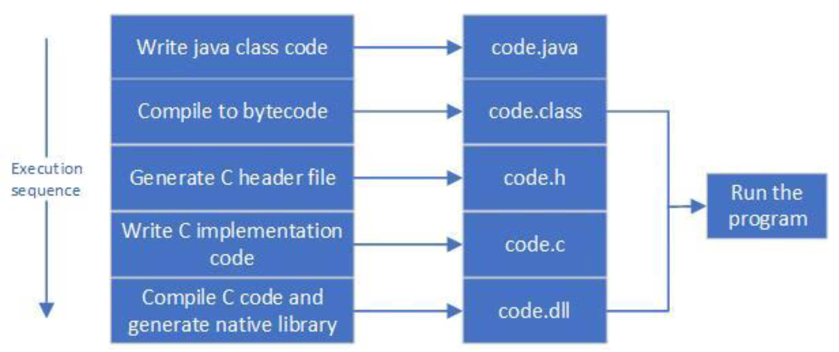
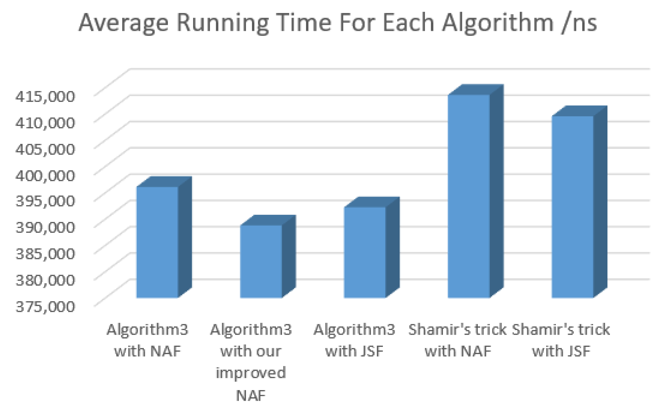
We also verify the efficiency results in the real mobile phone. We use Eclipse to edit the Java code and the C code of those five algorithms in Table 2. Additionally, JNI (Java Native Interface) is employed to realize the interaction between the C code and the Java code. The interaction process of the five algorithms’ codes is shown in Figure 4. Here, the C code is responsible for operating the CPU registers of the five algorithms. We then use Android Studio to implement them in the Android 10 system. For those five algorithms, the elliptic curve group is based on NIST’s P- 192 curve [1]. For each algorithm, the computation of 1,000,000 multi-scalar multiplications is carried out, and the average value of the running time is taken as the final result (see Figure 5). It can be seen that the efficiency results achieved on the physical device are basically consistent with our theoretical expectation.

5. Future Work

Three possible directions for future improvement are as follows.
(1) The optimal signed binary representation for the adaptive window method. In practice, the improved NAF representation in Section 3.1 can achieve the minimal performance factor among all well-known representations. However, we still do not know how to find the one with the best performance factor among all signed binary representations. Hence, it remains an open problem to find the optimal one for the adaptive window method with a fixed number of registers.
(2) The on-line strategy for the adaptive window method. To compute the multi-scalar multiplication x A + y B , the m -ary method and the sliding window method need to pre-compute and store all possible values for the w -bit pairs, where the integer w is the window size, and w > 1 . However, the adaptive window method only computes and stores part of them based on the number of available registers. Thus, it would be useful to check each w -bit pair in the sequence pair according to on-line input integers x and y , and then determine the high frequency values among all possible values in real time. Clearly, should those high frequency values be pre-computed and stored, the adaptive window method could be further improved in practical implementations. It might be interesting to investigate this on-line strategy further.
(3) The register-constrained implementation for the adaptive window method. We use the Java code linked with the C code to implement several multi-scalar multiplication algorithms on the mobile phone and obtain their corresponding efficiency results. However, both the device and the development tool are not perfect in consideration of the register-constrained environment. Embedded hardware microprocessors, such as Atmega and ARM, and the assembly code, are more suitable to simulate our proposed multi-scalar multiplication algorithms and verify their performance results. Additionally, the novel optimization implementation technique on our proposed algorithms may be designed according to the particular embedded hardware microprocessor. Hence, it is valuable work to further implement the adaptive window method in the embedded hardware microprocessors.

6. Conclusions

We have studied the cryptographic implementations of multi-scalar multiplication under register-constrained environments. In order to make the best of the available registers, our idea is not to store all possible values in the window, but only to store those with comparatively high probabilities. The computational complexity analysis and the experimental results show that the proposed adaptive window method achieves the notable computation efficiency with one more register provided. For embedded cryptographic applications, it is especially convenient for our method to balance the performance and the costs according to the computation and memory abilities of the embedded devices. We also expect that our research will inspire others to work in the fascinating algorithms of multi-scalar multiplication under resource-constrained environments.

Author Contributions

Conceptualization, D.-Z.S.; methodology, D.-Z.S.; validation, D.-Z.S. and J.-D.Z.; formal analysis, D.-Z.S.; investigation, H.-D.Z.; writing—original draft preparation, D.-Z.S. and H.-D.Z.; writing—review and editing, D.-Z.S. and X.-Y.G.; supervision, D.-Z.S. and J.-D.Z.; funding acquisition, D.-Z.S. All authors have read and agreed to the published version of the manuscript.

Funding

The work of Da-Zhi Sun was supported in part by the National Natural Science Foundation of China under Grant No. 61872264. The APC was funded by the National Natural Science Foundation of China under Grant No. 61872264.

Acknowledgments

The authors would like to thank the editor and the reviewers for their valuable suggestions and comments.

Conflicts of Interest

The authors declare no conflict of interest.

Appendix A. Some Notations Using in the Appendixes

Let ( x n 1 x n 2 x 0 ) SD and ( y n 1 y n 2 y 0 ) SD be the signed binary representations. Supposing   n , we write
(1) Pr ( α d α d 1 α 0 ) denotes the probability of any x i x i 1 x i d = α d α d 1 α 0 ;
(2) Pr ( α d α d 1 α 0 | β f β f 1 β 0 ) denotes the conditional probability of any x i f 1 x i f 2 x i f 1 d = α d α d 1 α 0 , given that x i x i 1   x i f = β f β f 1 β 0 ;
(3) Pr ( α d α d 1 α 0 β d β d 1 β 0 ) denotes the probability of any x i x i 1 x i d = α d α d 1 α 0 and y i y i 1 y i d = β d β d 1 β 0 ;
(4) Pr ( ( α d 1 α d 1 1 α 0 1 α d 2 α d 1 2 α 0 2 ) | ( β f 1 β f 1 1 β 0 1 β f 2 β f 1 2 β 0 2 ) ) denotes the probability of any x i f 1 x i f 2 x i f 1 d = α d 1 α d 1 1 α 0 1 and y i f 1 y i f 2 y i f 1 d = α d 2 α d 1 2 α 0   2 , given that x i x i 1 x i f = β f 1 β f 1 1 β 0 1 and y i y i 1 y i f = β f 2 β f 1 2 β 0 2 .
For example, Pr ( 0 1 ^ 00 ) , Pr ( 0 1 | 0 1 ^ ) , Pr ( 0 1 0 1 1 0 1 ^ 0 ) , and Pr ( ( 1 ^ 0 0 1 ^ ) | ( 1 ^ 0 0 1 ^ ) ) , respectively, mean Pr ( x i x i 1 x i 2 x i 3 = 0 1 ^ 00 ) , Pr ( x i 2 x i 3 = 0 1 | x i x i 1 = 0 1 ^ ) , Pr ( ( x i x i 1 x i 2 x i 3 y i y i 1 y i 2 y i 3 ) = ( 0 1 0 1 1 0 1 ^ 0 ) ) , and Pr ( ( x i 2 x i 3 y i 2 y i 3 ) = ( 1 ^ 0 0 1 ^ ) | ( x i x i 1 y i y i 1 ) = ( 1 ^ 0 0 1 ^ ) ) , when   n .

Appendix B. Some Facts of NAF Representation

To analyze the computational complexity of our proposed algorithms, we need first review two well-known properties of the NAF representation [18,19] as follows.
Lemma A1.
The NAF representation of an integer is unique. No two nonzero digits are adjacent in the representation.
Lemma A2.
For any bit of the NAF representation, the probabilities of 0 , 1 , and 1 are, respectively, 2 / 3 , 1 / 6 , and 1 / 6 . That is,
Pr ( 0 ) = 2 3  
and
Pr ( 1 ) = Pr ( 1 ) = 1 6 .
We can further give three useful properties of the NAF representation. The following three properties can be easily derived from the NAF coding algorithm.
Lemma A3.
For any two consecutive bits of the NAF representation,
Pr ( 00 ) = 1 3  
and
Pr ( 01 ) = Pr ( 0 1 ) = Pr ( 10 ) = Pr ( 10 ) = 1 6 .
Lemma A4.
For any three consecutive bits of the NAF representation,
Pr ( 000 ) = Pr ( 010 ) = Pr ( 0 10 ) = 1 6   ,
Pr ( 001 ) = Pr ( 00 1 ) = Pr ( 100 ) = Pr ( 100 ) = 1 12   ,
and
Pr ( 101 ) = Pr ( 10 1 ) = Pr ( 10 1 ) = 1 24 .
Lemma A5.
For any four consecutive bits of the NAF representation,
Pr ( 0000 ) = Pr ( 0010 ) = Pr ( 00 10 ) = Pr ( 0100 ) = Pr ( 0 100 ) = 1 12 ,
Pr ( 0001 ) = Pr ( 000 1 ) = Pr ( 1000 ) = Pr ( 1000 ) = Pr ( 0101 ) = Pr ( 0 101 ) = Pr ( 010 1 ) = Pr ( 0 10 1 ) = Pr ( 1010 ) = Pr ( 1010 ) = Pr ( 10 10 ) = Pr ( 10 10 ) = 1 24 ,
and
Pr ( 1001 ) = Pr ( 1001 ) = Pr ( 100 1 ) = Pr ( 100 1 ) = 1 48 .

Appendix C. Proof of Theorem 1

Proof. 
Consider that Figure 3 scans the input NAF sequence pair ( x n 1 x n 2 x 0 y n 1 y n 2 y 0 ) . Let P 0 , P 1 , P 2 , P 3 , P 4 , P 5 , P 6 , and P 7 , respectively, be the corresponding scanning states ( 0 0 ) , ( 1 0 0 1 ) , ( 1 0 0 1 ) , ( 1 0 ) , ( 1 0 ) , ( 0 1 ) , ( 0 1 ) , and ( 1 ^ 1 ^ ) . It means that one of Steps 3.1, 3.2, 3.3, 3.4, 3.5, and 4 is executed in Figure 3. Note that the NAF representations of the integers x and y are independent from each other. Based on the properties of the NAF representation, we can compute all one-step transition probabilities for the scanning states P i = 0 , 1 , 2 , 3 , 4 , 5 , 6 , 7 . For example, we can compute
Pr ( P 0 | P 0 ) = Pr ( ( 0 0 ) | ( 0 0 ) ) = Pr ( 0 | 0 ) Pr ( 0 | 0 ) = Pr ( 00 ) Pr ( 0 ) Pr ( 00 ) Pr ( 0 ) = 1 4
by Lemmas A2 and A3;
Pr ( P 0 | P 7 ) = Pr ( ( 0 0 ) | ( 1 ^ 1 ^ ) ) = Pr ( 0 | 1 ^ ) Pr ( 0 | 1 ^ ) = 1
by Lemma A1;
Pr ( P 2 | P 1 ) = Pr ( ( 1 0 0 1 ) | ( 1 0 0 1 ) ) = Pr ( 10 | 10 ) Pr ( 0 1 | 01 ) = Pr ( 10 10 ) Pr ( 10 ) Pr ( 010 1 ) Pr ( 01 ) = 1 16
by Lemmaa A3 and A5;
Pr ( P 3 | P 5 ) = Pr ( ( 1 0 0 0 ) | ( 0 1 ) ) + Pr ( ( 1 0 0 1 ) | ( 0 1 ) ) = Pr ( 10 | 0 ) Pr ( 00 | 1 ) + Pr ( 10 | 0 ) Pr ( 0 1 | 1 ) = Pr ( 010 ) Pr ( 0 ) Pr ( 100 ) Pr ( 1 ) + Pr ( 010 ) Pr ( 0 ) Pr ( 10 1 ) Pr ( 1 ) = 3 16
by Lemmas A2 and A4.
Thus, the one-step transition probability matrix of the states P i = 0 , 1 , 2 , 3 , 4 , 5 , 6 , 7 is
[ Pr ( P 0 | P 0 ) Pr ( P 1 | P 0 ) Pr ( P 7 | P 0 ) Pr ( P 0 | P 1 ) Pr ( P 1 | P 1 ) Pr ( P 7 | P 1 ) Pr ( P 0 | P 7 ) Pr ( P 1 | P 7 ) Pr ( P 7 | P 7 ) ] = [ 1 4 1 32 1 32 3 32 3 32 1 8 1 8 1 4 1 2 1 16 1 16 3 16 3 16 0 0 0 1 2 1 16 1 16 3 16 3 16 0 0 0 2 3 0 0 0 0 0 1 3 0 2 3 0 0 0 0 1 3 0 0 1 2 1 16 1 16 3 16 3 16 0 0 0 1 2 1 16 1 16 3 16 3 16 0 0 0 1 0 0 0 0 0 0 0 ] ,
where Pr ( P 0 j 7 | P 0 k 7 ) denotes the conditional probability of the next state given the current state P k .
Since the matrix T B N A F 5 2 has all positive elements, this Markov chain is a regular chain. Let Pr ( P 0 i 7 ) be the probability of the state P i as   n . According to the theorems of the regular Markov chain, we have
{ Pr ( P 0 ) = 16 34 Pr ( P 1 ) = Pr ( P 2 ) = 1 34 Pr ( P 3 ) = Pr ( P 4 ) = Pr ( P 5 ) = Pr ( P 6 ) = 3 34 Pr ( P 7 ) = 4 34 .
In Figure 3, we can see that the state P 0 needs no point addition, and each state P 1 i 7 needs one point addition. Thus, on average, the asymptotic performance factor is
w B N A F 5 ( n ) = Pr ( P 1 ) + Pr ( P 2 ) + Pr ( P 3 ) + Pr ( P 4 ) + Pr ( P 5 ) + Pr ( P 6 ) + Pr ( P 7 ) Pr ( P 0 ) + 2 Pr ( P 1 ) + 2 Pr ( P 2 ) + Pr ( P 3 ) + Pr ( P 4 ) + Pr ( P 5 ) + Pr ( P 6 ) + Pr ( P 7 ) n = 1 34 + 1 34 + 3 34 + 3 34 + 3 34 + 3 34 + 4 34 16 34 + 2 34 + 2 34 + 3 34 + 3 34 + 3 34 + 3 34 + 4 34 n = n 2 .

Appendix D. Proof of Theorem 2

Proof. 
Consider the 3 -bit or 4 -bit pairs in the recoding rules. Based on the scanning process of the input NAF sequence pair ( x n 1 x n 2 x 0 y n 1 y n 2 y 0 ) in Figure 3, each 3 -bit pair using Rule A1, A2, A3, or A4 requires two point additions before the recoding process. However, it requires only one point addition after the recoding process. For example, the 3 -bit pair ( 1 0 1 0 1 0 ) , consecutively, needs to pass Steps 3.3 and 3.4 of Figure 3 for the first two columns, and Steps 3.3 and 3.4 requires in total two point additions. Comparably, the 3 -bit pair ( 0 1 1 0 1 0 ) needs to execute Steps 3.1 and 3.5 of Figure 3 for the first two columns, which requires one point addition instead. Similarly, each 4 -bit pair using Rule A5, A6, A7, or A8 requires three point additions before the recoding process, but requires two point additions after the recoding process.
Next, according to Rules A1, A2, A3, A4, A5, A6, A7, and A8, we calculate the probabilities of those 3 -bit and 4 -bit pairs appeared in the NAF representation. We can obtain
Pr ( 1 0 1 0 1 0 ) = Pr ( 1 0 1 0 1 0 ) = Pr ( 0 1 0 1 0 1 ) = Pr ( 0 1 0 1 0 1 ) = 1 144
and
Pr ( 1 0 1 0 0 0 0 1 ) = Pr ( 1 0 1 0 0 0 0 1 ) = Pr ( 1 0 1 0 0 1 0 1 ) = Pr ( 1 0 1 0 0 1 0 1 ) = 1 576
by Lemmas A4 and A5.
Consequently, it follows from Theorem 1 that the performance factor of the improved Figure 3 can be estimated as
w I N A F 5 ( n ) = w B N A F 5 ( n ) w R N A F 5 ( n ) n 2 ( 4 2 Pr ( 1 0 1 0 1 0 ) + 4 3 Pr ( 1 0 1 0 0 0 0 1 ) ) n = 209 n 432 ,
where w R N A F 5 ( n ) denotes the number of saving point additions due to Rules A1, A2, A3, A4, A5, A6, A7, and A8.

Appendix E. Some Facts of JSF Representation

To analyze the 5 -register algorithm using the JSF representation, we need the following important fact of the JSF representation.
Lemma A6.
Assume that the scan process of the sliding window method [22] is used for the JSF sequence pair ( x n 1 x n 2 x 0 y n 1 y n 2 y 0 ) , and the window size w = 2 . Let η be any 2 -bit pair appeared in the JSF sequence pair, that is,   η { ( 1 ^ 0 0 1 ^ ) ,   ( 0 1 ^ 1 ^ 0 ) , ( 1 1 1 ^ 0 ) , ( 1 1 1 ^ 0 ) ,   ( 1 ^ 0 1 1 ) , ( 1 ^ 0 1 1 ) } . On average, the probabilities of all possible pairs are
Pr ( 0 0 ) = 1 2   ,
Pr ( 1 ^ 0 ) = Pr ( 0 1 ^ ) = 3 32   ,
Pr ( 1 ^ 1 ^ ) = 3 16   ,
and
Pr ( η ) = 1 128   ,
when   n .
Proof. 
We assume that the reader is already acquainted with the results in Solinas’ technical report [11], from which we recall a few important facts. For the JSF coding algorithm, the JSF coding output ( x i y i ) is a function of the internal current state S j , where 0 i n 1 and 0 j 7 . We can further extend the detailed relations between the states and the corresponding outputs as follows:
(1) S 0 maps to the current output ( 0 0 ) ;
(2) S 1 maps to the case where the current output is ( 0 1 ^ ) and the next output will be ( 0 0 ) ;
(3) S 2 maps to the case where the current output is ( 0 1 ^ ) and the next output will be ( 1 ^ 0 ) ;
(4) S 3 maps to the case where the current output is ( 0 1 ^ ) and the next output will be ( 1 ^ 1 ^ ) ;
(5) S 4 maps to the case where the current output is ( 1 ^ 0 ) and the next output will be ( 0 0 ) ;
(6) S 5 maps to the case where the current output is ( 1 ^ 0 ) and the next output will be ( 0 1 ^ ) ;
(7) S 6 maps to the case where the current output is ( 1 ^ 0 ) and the next output will be ( 1 ^ 1 ^ ) ;
(8) S 7 maps to the current output ( 1 ^ 1 ^ ) .
According to Solinas’ result, the one-step transition probability matrix of the states S j = 0 , 1 , 2 , 3 , 4 , 5 , 6 , 7 is
T J S F = [ Pr ( S 0 | S 0 ) Pr ( S 1 | S 0 ) Pr ( S 7 | S 0 ) Pr ( S 0 | S 1 ) Pr ( S 1 | S 1 ) Pr ( S 7 | S 1 ) Pr ( S 0 | S 7 ) Pr ( S 1 | S 7 ) Pr ( S 7 | S 7 ) ] = [ 1 4 1 8 1 16 1 16 1 8 1 16 1 16 1 4 1 0 0 0 0 0 0 0 0 0 0 0 1 0 0 0 0 0 0 0 0 0 0 1 1 0 0 0 0 0 0 0 0 1 0 0 0 0 0 0 0 0 0 0 0 0 0 1 1 0 0 0 0 0 0 0 ] .
Since all the elements in the matrix T J S F 3 are positive, this Markov chain is a regular chain. Let Pr ( S 0 j 7 ) be the probability of the state S j as   n . According to the theorems of the regular Markov chain, we have
{ Pr ( S 0 ) = 1 2 Pr ( S 1 ) = Pr ( S 4 ) = 3 32 Pr ( S 2 ) = Pr ( S 3 ) = Pr ( S 5 ) = Pr ( S 6 ) = 1 32 Pr ( S 7 ) = 3 16 .
Because of previous relations between the states and the corresponding outputs, we know
{ Pr ( S 0 ) = Pr ( 0 0 ) = 1 2 Pr ( S 1 ) = Pr ( 0 1 ^ ) = Pr ( S 4 ) = Pr ( 1 ^ 0 ) = 3 32 Pr ( S 2 ) = Pr ( 1 ^ 0 0 1 ^ ) = Pr ( S 3 ) = Pr ( 1 ^ 0 1 ^ 1 ^ ) = Pr ( S 5 ) = Pr ( 0 1 ^ 1 ^ 0 ) = Pr ( S 6 ) = Pr ( 1 ^ 1 ^ 1 ^ 0 ) = 1 32 Pr ( S 7 ) = Pr ( 1 ^ 1 ^ ) = 3 16 .    
Furthermore, by the JSF coding algorithm, i.e., Algorithm Shamir’s trick in Figure 1 in [11], all possible 2 -bit pairs ( 1 0 0 1 ) , ( 1 0 0 1 ) , ( 1 0 0 1 ) , ( 1 0 0 1 ) , ( 1 0 1 1 ) , ( 1 0 1 1 ) , ( 1 0 1 1 ) , ( 1 0 1 1 ) , ( 0 1 1 0 ) , ( 0 1 1 0 ) , ( 0 1 1 0 ) , ( 0 1 1 0 ) , ( 1 1 1 0 ) , ( 1 1 1 0 ) , ( 1 1 1 0 ) , and ( 1 1 1 0 ) should have the same probability. It means that
Pr ( η ) = 1 128 .

Appendix F. Proof of Theorem 3

Proof. 
Our 5 -register algorithm using the JSF representation is almost the same as Figure 3 but with the input x and y represented in the JSF. By Lemma A6, our algorithm is optimal. Because the value 2 A + B is stored in Step 1 of Figure 3, the 2 -bit pairs ( 1 0 0 1 ) and ( 1 0 0 1 ) in the JSF sequence pair ( x n 1 x n 2 x 0 y n 1 y n 2 y 0 ) only require one point addition. Therefore, the corresponding performance factor is
w J S F 5 ( n ) =   ( 16 Pr ( η ) + Pr ( 1 ^ 0 ) + Pr ( 0 1 ^ ) Pr ( 1 0 0 1 ) Pr ( 1 0 0 1 ) + Pr ( 1 ^ 1 ^ ) ) n = 31 n 64 .

References

  1. National Institute of Standards and Technology. Federal Information Processing Standards Publication 186-3: Digital Signature Standard (DSS). 2009. Available online: https://csrc.nist.gov/csrc/media/publications/fips/186/3/archive/2009-06-25/documents/fips_186-3.pdf (accessed on 5 November 2020).
  2. American National Standards Institute. ANSI X9.62: Public Key Cryptography for the Financial Services Industry: The Elliptic Curve Digital Signature Algorithm (ECDSA); American National Standards Institute: New York, NY, USA, 2005. [Google Scholar]
  3. Schnorr, C.P. Efficient signature generation by smart cards. J. Cryptol. 1991, 4, 161–174. [Google Scholar] [CrossRef] [Green Version]
  4. Fuchsbauer, G.; Orrù, M.; Seurin, Y. Aggregate Cash Systems: A Cryptographic Investigation of Mimblewimble. In Proceedings of the 38th Annual International Conference on the Theory and Applications of Cryptographic Techniques Selected Areas in Cryptography (EUROCRYPT 2019), Part I, Darmstadt, Germany, 19–23 May 2019; Ishai, Y., Rijmen, V., Eds.; Lecture Notes in Computer Science. Springer: Cham, Switzerland, 2019; Volume 11476, pp. 657–689. [Google Scholar]
  5. Sun, D.Z.; Sun, L.; Yang, Y. On secure simple pairing in Bluetooth standard v5.0-part II: Privacy analysis and enhancement for low energy. Sensors 2019, 19, 3259. [Google Scholar] [CrossRef] [Green Version]
  6. Zhang, Y.D.; He, D.B.; Zhang, M.W.; Choo, K.K.R. A provable-secure and practical two-party distributed signing protocol for SM2 signature algorithm. Front. Comput. Sci. China 2020, 14, 143803. [Google Scholar] [CrossRef]
  7. Chen, E.; Zhu, Y.; Lin, C.L.; Lv, K.W. Zero-pole cancellation for identity-based aggregators: A constant-size designated verifier-set signature. Front. Comput. Sci. China 2020, 14, 144806. [Google Scholar] [CrossRef]
  8. Gordon, D.M. A survey of fast exponentiation methods. J. Algorithms 1998, 27, 129–146. [Google Scholar] [CrossRef] [Green Version]
  9. ElGamal, T. A public key cryptosystem and a signature scheme based on discrete logarithms. IEEE Trans. Inf. Theory 1985, 31, 469–472. [Google Scholar] [CrossRef]
  10. Dimitrov, V.S.; Jullien, G.A.; Miller, W.C. Complexity and fast algorithms for multiexponentiations. IEEE Trans. Comput. 2000, 49, 141–147. [Google Scholar] [CrossRef]
  11. Solinas, J.A. Low-Weight Binary Representations for Pairs of Integers; Combinatorics and Optimization Research Report CORR 2001-41, Centre for Applied Cryptographic Research, University of Waterloo. 2001. Available online: http://www.cacr.math.uwaterloo.ca/techreports/2001/corr2001-41.ps (accessed on 5 November 2020).
  12. Grabner, P.J.; Heuberger, C.; Prodinger, H. Distribution results for low-weight binary representations for pairs of integers. Theor. Comput. Sci. 2004, 319, 307–331. [Google Scholar] [CrossRef]
  13. Yang, W.C.; Guan, D.J.; Laih, C.S. Algorithm of asynchronous binary signed-digit recoding on fast multiexponentiation. Appl. Math. Comput. 2005, 167, 108–117. [Google Scholar] [CrossRef]
  14. Ruan, X.Y.; Katti, R.S. Left-to-right optimal signed-binary representation of a pair of integers. IEEE Trans. Comput. 2005, 54, 124–131. [Google Scholar] [CrossRef]
  15. Sun, D.Z.; Huai, J.P.; Sun, J.Z.; Zhang, J.W. Computational efficiency analysis of Wu et al.’s fast modular multi-exponentiation algorithm. Appl. Math. Comput. 2007, 190, 1848–1854. [Google Scholar] [CrossRef]
  16. Sun, D.Z.; Huai, J.P.; Sun, J.Z.; Li, J.X. Analysis of multi-exponentiation algorithm using binary signed-digit representations. Int. J. Comput. Methods 2009, 6, 307–315. [Google Scholar] [CrossRef]
  17. Yang, W.C.; Hung, C.P. Analysis of the Dimitrov-Jullien-Miller recoding algorithm. IEICE Trans. Fundam. Electron. Commun. Comput. Sci. 2016, E99A, 139–144. [Google Scholar] [CrossRef]
  18. Arno, S.; Wheeler, F.S. Signed digit representations of minimal hamming weight. IEEE Trans. Comput. 1993, 42, 1007–1010. [Google Scholar] [CrossRef]
  19. Menezes, A.; van Oorschot, P.; Vanstone, S. Handbook of Applied Cryptography; CRC Press: Boca Raton, FL, USA, 1997; pp. 627–628. [Google Scholar]
  20. Yen, S.M.; Laih, C.S.; Lenstra, A.K. Multi-exponentiation. IEE Proc. Comp. Digit. Tech. 1994, 141, 325–326. [Google Scholar] [CrossRef] [Green Version]
  21. Möller, B. Algorithms for Multi-exponentiation. In Proceedings of the Selected Areas in Cryptography (SAC 2001), Toronto, ON, Canada, 16–17 August 2001; Vaudenay, S., Youssef, A.M., Eds.; Lecture Notes in Computer Science. Springer: Berlin/Heidelberg, Germany, 2001; Volume 2259, pp. 165–180. [Google Scholar]
  22. Avanzi, R.M. The complexity of certain multi-exponentiation techniques in cryptography. J. Cryptol. 2005, 18, 357–373. [Google Scholar] [CrossRef]
  23. Yang, W.C.; Guan, D.J.; Laih, C.S. Fast multicomputation with asynchronous strategy. IEEE Trans. Comput. 2007, 56, 234–242. [Google Scholar] [CrossRef]
  24. Sun, D.Z.; Huai, J.P.; Li, J.X. A note on asynchronous multi-exponentiation algorithm using binary representation. Inf. Process. Lett. 2012, 112, 876–879. [Google Scholar] [CrossRef]
  25. Chevalier, C.; Laguillaumie, F.; Vergnaud, D. Privately outsourcing exponentiation to a single server: Cryptanalysis and optimal constructions. Algorithmica 2020, 83, 72–115. [Google Scholar] [CrossRef]
  26. Borges, F.; Lara, P.; Portugal, R. Parallel algorithms for modular multi-exponentiation. Appl. Math. Comput. 2017, 292, 406–416. [Google Scholar] [CrossRef]
  27. Topcuoglu, C.; Kaya, K.; Savas, E. A generic private information retrieval scheme with parallel multi-exponentiations on multicore processors. Concurr. Comput. Pract. Exp. 2018, 30, e4685. [Google Scholar] [CrossRef]
  28. Tao, R.; Liu, J.; Su, H.; Sun, Y.; Liu, X. Combination in Advance Batch Multi-exponentiation on Elliptic Curve. In Proceedings of the 2015 IEEE 2nd International Conference on Cyber Security and Cloud Computing (CSCloud 2015), New York, NY, USA, 3–5 November 2015; Qiu, M.K., Zhang, T., Das, S., Eds.; IEEE Computer Society: Washington, DC, USA, 2015; pp. 411–416. [Google Scholar]
  29. Wu, Q.H.; Sun, Y.; Qin, B.; Hu, J.K.; Liu, W.R.; Liu, J.W.; Ding, Y. Batch public key cryptosystem with batch multi-exponentiation. Futur. Gener. Comp. Syst. 2016, 62, 196–204. [Google Scholar] [CrossRef]
  30. Atmel Corporation. 8-Bit AVR Microcontroller with 128K Bytes In-System Programmable Flash. 2007. Available online: http://ww1.microchip.com/downloads/en/DeviceDoc/doc0945.pdf (accessed on 5 February 2021).
  31. ARM. ARM7TDMI Technical Reference Manual (Rev 3). 2017. Available online: http://ww1.microchip.com/downloads/en/DeviceDoc/DDI0029G_7TDMI_R3_trm.pdf (accessed on 5 February 2021).
  32. Hankerson, D.; Menezes, A.; Vanstone, S. Guide to Elliptic Curve Cryptography; Springer: New York, NY, USA, 2004; pp. 109–113. [Google Scholar]
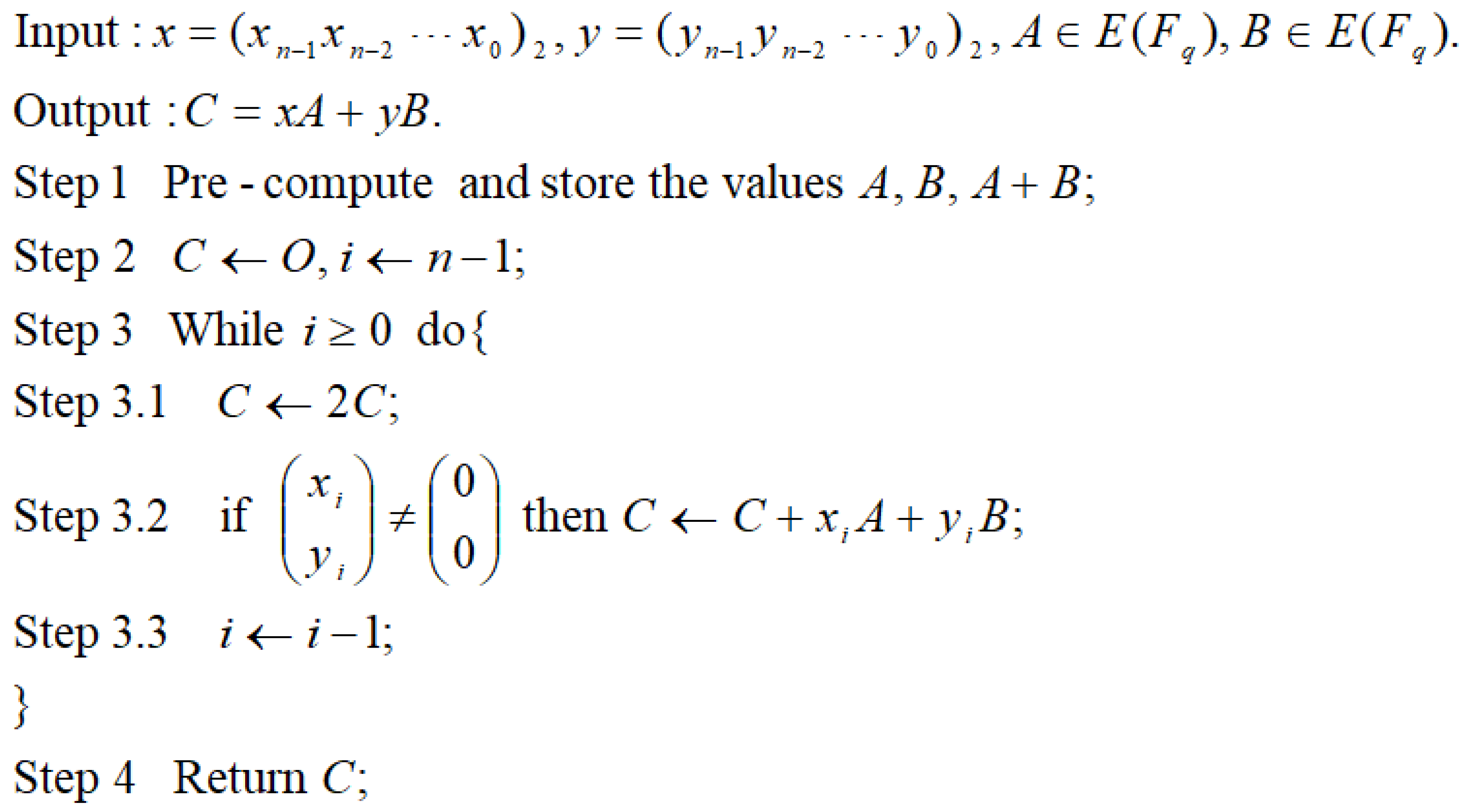
Figure 1. Algorithm Shamir’s trick.
Electronics 10 00605 g001
Figure 2. Algorithm Adaptive window method.
Electronics 10 00605 g002
Figure 3. Algorithm The 5-register algorithm using the non-adjacent form (NAF) representation.
Electronics 10 00605 g003
Figure 4. Implementation frame of the five algorithms by using Java Native Interface (JNI).
Electronics 10 00605 g004
Figure 5. Average running time for each algorithm.
Electronics 10 00605 g005
Table 1. Description of notations.
TermDefinition
F q Finite field with q elements
E ( F q ) Elliptic curve group E defined over a finite field F q
OThe point at infinity on E ( F q )
A ,   B Any two points on E ( F q )
A + B The point addition applied to A E ( F q ) and B E ( F q )
2 A The point doubling applied to A E ( F q ) , i.e., A + A
x A The scalar multiplication by an integer x applied to   A E ( F q ) , i.e., A + A + + A x   t i m e s
( x n 1 x n 2 x 0 ) 2 , ( y n 1 y n 2 y 0 ) 2 The binary representations of the integers x and y
( x n 1 x n 2 x 0 ) SD , ( y n 1 y n 2 y 0 ) SD Any signed binary representations of the integers x and y , i.e., x i ,   y i { 1 ,   1 ,   0 }
( x n 1 x n 2 x 0 ) NAF , ( y n 1 y n 2 y 0 ) NAF The non-adjacent form (NAF) representations of the integers x and y
( x n 1 x n 2 x 0 y n 1 y n 2 y 0 ) The signed sequence pair of the integers x and y , where x n 1 x n 2 x 0 and y n 1 y n 2 y 0 are, respectively, the certain signed binary representations of the integers x and y
n The bit length of the integers x and y using the binary representations or the signed binary representations
1 ^ Any bit 1 or 1
w ( n ) The performance factor of a certain multi-scalar multiplication algorithm, i.e., the number of point additions required by the algorithm
w S T ( n ) The performance factor of Shamir’s trick using the binary representation
w N A F 4 ( n ) The performance factor of Shamir’s trick using the NAF representation
w J S F 4 ( n ) The performance factor of Shamir’s trick using the joint sparse form (JSF) representation
w B N A F 5 ( n ) The performance factor of the 5 -register adaptive window method using the NAF representation
w I N A F 5 ( n ) The performance factor of the 5 -register adaptive window method using the improved NAF representation
w J S F 5 ( n ) The performance factor of the 5 -register adaptive window method using the JSF representation
Pr ( E V ) The probability that the event E V occurs
Pr ( E V 1 | E V 2 ) The conditional probability of the event E V 1 given the event E V 2
Table 2. Comparison with the related methods.
AlgorithmsNumber of RegistersPerformance Factor Constant Theoretical ValuePerformance Factor Constant Experimental Value
Figure 351/2 = 0.50.499962
Figure 3 with our improved NAF5209/432 ≈ 0.4837960.483781
Figure 3 using JSF531/64 = 0.4843750.484313
Shamir’s trick with NAF45/9 = 0.5555560.555466
Shamir’s trick with JSF41/2 = 0.50.500036
Shamir’s trick with 3-NAF interleaving [32]41/2 = 0.50.500014
Publisher’s Note: MDPI stays neutral with regard to jurisdictional claims in published maps and institutional affiliations.