Abstract
This paper presents a pipelined layered quasi-cyclic low-density parity-check (QC-LDPC) decoder architecture targeting low-complexity, high-throughput, and efficient use of hardware resources compliant with the specifications of 5G new radio (NR) wireless communication standard. First, a combined min-sum (CMS) decoding algorithm, which is a combination of the offset min-sum and the original min-sum algorithm, is proposed. Then, a low-complexity and high-throughput pipelined layered QC-LDPC decoder architecture for enhanced mobile broadband specifications in 5G NR wireless standards based on CMS algorithm with pipeline layered scheduling is presented. Enhanced versions of check node-based processor architectures are proposed to improve the complexity of the LDPC decoders. An efficient minimum-finder for the check node unit architecture that reduces the hardware required for the computation of the first two minima is introduced. Moreover, a low complexity a posteriori information update unit architecture, which only requires one adder array for their operations, is presented. The proposed architecture shows significant improvements in terms of area and throughput compared to other QC-LDPC decoder architectures available in the literature.
1. Introduction
Low-density parity-check (LDPC) codes [1] were first introduced by R. Gallager in the early 1960s and later rediscovered by MacKay and Neal [2] in 1996. Due to their excellent error correction performance and highly parallel implementation characteristics, LDPC codes have been considered as one of the most popular forward error correction (FEC) codes in the past several decades. Since then, LDPC codes served as a fundamental of modern coding theory, which relies mainly on Shannon theory [3] in addition to extremely sparse code characterization and probabilistic message-passing algorithms [4]. Moreover, LDPC codes inherently possess some of the good characteristics of linear block codes, for instance, the simple and sparseness structure of parity check matrix H, which can be sketched in the shape of a bipartite model called Tanner graph [5]. A graphical approach makes it easier to analyze and visualize all complex mathematical formulations [6].
With higher data rates and acceptable error correction performance, the realizations of channel coding schemes have become crucial for all modern communication systems. The decoding of an LDPC can be deployed with a high degree of parallelism, which is essential to achieve high decoding throughput and low hardware complexity. Therefore, LDPC codes are promising solutions for high data rate applications such as wide-band wireless multimedia communications and magnetic storage systems [7,8]. Generally, well-constructed irregular LDPC codes show much higher performance than the regular ones [9]. Although construction of very-large-scale integration (VLSI) architecture for irregular LDPC codes consumes higher complexity, many practical applications and standards such as IEEE 802.16e [10] and IEEE 802.11n [11,12] have considered irregular LDPC codes since they have greater performance. In addition, millimeter-wave (mmWave) Wireless Gigabit (WiGig) introduced by the IEEE 802.11ad Working Group [13] considered LDPC codes as their favored option for FEC. Recently, LDPC codes have been deployed in the enhanced mobile broadband (eMBB) as the error correction coding scheme for fifth-generation (5G) data channels [14]. The third generation partnership project (3GPP) has introduced two base graph (BG) matrices, namely BG1 and BG2 [15,16,17], to support the scalable and rate-compatible data transmission.
In recent years, many studies concentrated on structured LDPC codes, also known as quasi-cyclic low-density parity-check (QC-LDPC) codes [18,19,20,21,22], which have been offered significant advantages over other types of LDPC codes in terms of hardware implementation and excellent error performance over noisy channels. Furthermore, QC-LDPC codes are relatively flexible and can be constructed with multiple code rates, numerous block lengths, and several different sizes of submatrix [23,24], which are important features of the modern mobile and wireless communication systems. Structured codes also consist of block-LDPC codes and architecture-aware LDPC codes [25,26]. The parity-check matrix H of QC-LDPC codes is composed of either cyclic permutation submatrices or zero matrices of the same size, which define the interconnection between the check node units (CNUs) and variable node units (VNUs).
The 5G mobile communications systems offer a far higher performance level beyond former generations of mobile communications systems. Wireless data traffic is estimated to increase by 1000-fold by the end of 2020 with more than 50 billion mobile devices connected to these wireless networks with peak data rates up to 10 Gbps. Forward error correction plays an extremely crucial role in high-speed communication systems. The search for an efficient trade-off between high performance, high throughput capabilities, low hardware complexity, low cost, and low power consumption makes the hardware implementation of an LDPC decoder still challenging. In addition, the researcher has to deal with many possible options of algorithms, quantization parameters, parallelisms, code rates, and frame lengths. Furthermore, a reduced area and power are particularly compulsory for mobile devices. Therefore, designs of the area and energy-efficient FEC chips are excessively desirable. This brief presents low-complexity and high-throughput QC-LDPC decoder architectures for emerging 5G wireless communications standards.
The remainder of this paper is structured as follows. In Section 2, a brief overview of the 5G NR LDPC codes is presented. Section 3 proposes a combined min-sum (CMS) decoding algorithm, which is a combination of the offset min-sum (OMS) and the original min-sum (MS) algorithm. Section 4 details the proposed low-complexity high-throughput pipelined layered QC-LDPC decoder for 5G NR wireless communication standards. Section 5 provides implementation and comparison results. Finally, conclusions are drawn in Section 6.
2. 5G New Radio LDPC Codes
2.1. Introduction
According to ITU-R, there are three primary 5G NR use cases defined by the 3GPP as part of its Study on New Services and Markets Technology Enablers (SMARTER) project. The three sets of use cases are [27]: eMBB, Ultra-Reliable Low Latency Communications (URLLC), and Massive Machine Type Communications (mMTC).
The initial phase of 5G deployments focuses on the eMBB use case. The eMBB traffic can be regarded as a direct extension from the 4G broadband service. The eMBB scenario is required to support a wider range of code rates, various code lengths, and modulation orders compared to the 4G Long Term Evolution (LTE). The eMBB offers peak data rates of 20 Gbps and provided user data rates of 100 Mbps to numerous users. Recently, LDPC codes have been selected as the coding scheme for the 5G eMBB data channel [14]. The NR access technology marks a great transition in channel coding for the 3GPP cellular technologies [28]. This section summarizes the basic features of standard 5G QC-LDPC codes. Furthermore, the construction procedures of the parity-check matrix of the target LDPC codes are also presented.
2.2. Quasi-Cyclic LDPC Codes
QC-LDPC codes [29], which are a class of structured LDPC codes, are widely used in many practical applications. A binary QC-LDPC code is characterized by the null space of an parity-check matrix H, which consists of an array of circulant matrices of the same size [30,31]. The parity-check matrix of a QC-LDPC code can be illustrated by its base graph and shift coefficients. Elements 1s in the base graph are replaced by a circulant permutation matrix of size and 0 s are replaced by and a zero matrix of the same size.
Denote Z as the size of a circulant permutation matrix and as the shift coefficient value. For any integer value , , a circulant permutation matrix is defined as the cyclic-shift of the identity matrix I to the right by times for the th non-zero element in a base matrix. This binary circulant permutation matrix is denoted as . For simple notation, denotes the null matrix (i.e., all elements equal to zero) of the same size. Considering as an example,
For two positive integers and , with , consider the QC-LDPC code expressed by the following array of circulants over GF(2):
The exponent matrix of H, which is , has the following form:
Each entry in the matrix E is denoted as a shift value. It should be noted that the parity-check matrix H in Equation (2) can be constructed by expanding the exponent matrix . This procedure is referred to as protograph construction [32]. It follows that the parity-check matrix H is of size where and .
2.3. 5G New Radio QC-LDPC Characteristics
As stated before, QC-LDPC codes play a significant role in 5G NR communications and have been deployed as the error correction coding scheme for the 5G eMBB data channel in 3GPP standard meeting. Figure 1 shows the general structure of the base graph for the NR QC-LDPC codes. The columns are composed of three parts: information columns, core parity columns, and extension parity columns. The rows are divided into two parts: core check rows and extension check rows. As can be observed, the base matrix is partitioned into five submatrices, namely, A, B, O, C, and I [17]. Submatrix A corresponds to systematic bits. In addition, B corresponds to the first set of parity bits and is a square matrix with a dual-diagonal structure: its first column is of weight 3, whereas the submatrix is composed of other columns after the first column has an upper dual-diagonal structure. Submatrix O is an all-zero matrix. For the efficient support of Incremental Redundancy Hybrid Automatic Repeat Request (IR-HARQ), a single parity-check (SPC)-based extension is used to support lower rates, as shown in Figure 1. Submatrix C corresponds to SPC rows, and I is an identity matrix that corresponds to the second set of parity bits, i.e., the SPC extension. The combination of A and B is referred to as the kernel, and the other parts (O, C, and I) are referred to as extensions. This code structure is similar to the Raptor-like extension, as described in [15].
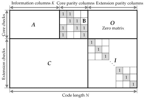
Figure 1.
Sketch of base parity-check structure for the 5G new radio (NR) quasi-cyclic low-density parity-check (QC-LDPC) codes.
The 3GPP has finalized two types of rate-compatible base graphs for the channel coding, naming BG1 and BG2. Base graphs BG1 and BG2 have relatively similar structures. However, BG1 is designed for larger block lengths and higher rates , whereas BG2 is deployed for smaller block lengths and lower rates . The actual base graph usage and the definition of the two base matrices are provided in the NR standard specification TS 38.212 [15]. The base graph that supports should support the following set of shift sizes Z, where for , and .
The number of shift coefficient designs for both base graphs BG1 and BG2 is 8. All lift sizes are categorized into eight sets based on parameter a, where a is used for the definition of the lifting-size . Table 1 presents the set of shift coefficients.

Table 1.
Relationship between exponent matrices and sets of lifting size.
The shift value can be calculated using the function , where is the shift coefficient of the th element in the corresponding shift design. The function f is defined as Equation (4), in which denotes the modulo arithmetic.
The five steps for constructing the parity-check matrix of the QC-LDPC code with a target information block size K and code rate are listed below. For a base graph, let denote the number of information circulant columns; thus, if the lifting size is Z, nominally.
- Step 1: Consider the base graph BG1 or BG2 and select the value of for the corresponding K and R.
- –
- For BG1: .
- –
- For BG2: if ; if ; if ; and
-
Table 2. Lifting size Z supported by standard 5G QC-LDPC codes.
- Step 3: After the lifting size Z is determined, the corresponding shift coefficient matrix is then picked up from Table 1 {Set 1, Set 2,⋯, Set 8} according to Z.
- Step 4: Calculate the shifting coefficient value by the modular Z operation, as defined in Equation (4).
- Step 5: Substitute each entry in the final exponent matrix by the corresponding circulant permutation matrix or zero matrix of size . The QC-LDPC code construction is accomplished, and a parity-check matrix H of size is achieved.
In 5G QC-LDPC codes, a shortening and puncturing process is performed to achieve the desired information lengths and rate adaption. An illustration of the encoding process of 5G QC-LDPC codes is presented in Figure 2.
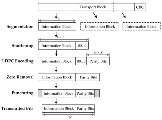
Figure 2.
Shortening by zero-padding and puncturing of standard 5G QC-LDPC codes.
3. Combined Min-Sum Algorithm
The standardized LDPC codes for 5G NR channel coding consider two base matrices: BG1 and BG2 [15,16,17], to support the rate compatible and scalable data transmission. An example of BG1 matrix structure with is presented in Figure 3. Efficient LDPC decoder implementation is a significant task while designing the physical layer for any wireless standard. It possesses many research challenges at the very early stage of wireless standards deployment. Therefore, it is time to conceive efficient LDPC decoder architecture that is compliant with the next generation of 5G NR standards. As shown in Figure 3, the significant challenge is to design an LDPC decoder architecture to support a huge BG1 matrix that generates the decoded bits of 3808 encoded information bits. Our work aims to present an efficient LDPC decoder architecture for the 5G NR wireless communication systems.
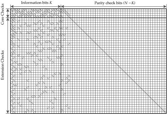
Figure 3.
Schematic representation of base matrix base graph (BG)1 defined by 5G NR standard for generating a QC-LDPC code of code length N = 3808 bits, code rate , and .
A considerable characteristic of the 5G NR LDPC codes is that these codes are dramatically irregular for both check nodes and variable nodes. Table 3 shows the distribution of check node degree in the two base graphs BG1 and BGs specified in 5G NR LDPC codes. For BG1, the check node degree varies largely from 3 to 19. More especially, there are only four rows in the core part of BG1 that possess the highest check node degree of = 19, while most of the rows are with low check node degrees of = 5 and 6. Similarly, the check node degree in BG2 also varies largely from 3 to 10 and only 2 rows are with = 10. It can be concluded that the check node degrees in the two base matrices of 5G NR LDPC codes vary drastically.
Table 3.
Check node degree distribution for 5G NR LDPC codes.
LDPC codes for the channel coding of 5G NR are actually concatenated codes that are derived by combining a pure LDPC part and a low-density generator matrix (LDGM) part. There is a significant difference in the check node degrees of the 5G LDPC codes, where the check node degree of the pure LDPC part is more than ten, and the check node degree is only one in the LDGM part. This creates one of the biggest challenges to design a high-performance decoder for 5G LDPC codes since their inherent numerous degree-1 variable nodes are more prone to be erroneous. For most hardware implementations of the traditional LDPC decoders, the MS algorithm or the modified versions of it, such as normalized min-sum (NMS) and OMS, are adopted. The NMS algorithm is the most straightforward scheme for hardware implementation. However, it is relatively challenging to optimize the normalized factor for the LDPC codes in 5G NR due to the particularly large difference in the check node degrees. Generally, the decoding performance of the OMS algorithm is better than the MS algorithm since it is an enhanced version of the original MS algorithm. Nevertheless, it is not always true for the case of fixed-point decoder for 5G LDPC codes. As stated before, the degree-1 variable nodes in the LDGM part are more sensitive to errors due to the lack of check to variable node messages. Furthermore, the offset factor of the OMS algorithm is relatively difficult to optimize in fixed point LDPC decoders because of limited quantization bits. Therefore, the performance of the OMS algorithm is much lower than the MS algorithm for fixed-point 5G LDPC decoders. Based on the considerable variation characteristic of the check node degree in 5G NR LDPC codes, a combined min-sum algorithm is introduced in this section. The combined algorithm adopts improved error correction performance by using different decoding algorithms for the core and extension parts of the LDPC code. The principal of the CMS algorithm is to apply the OMS algorithm for layers with a high check node degree in the core part and the original MS algorithm for the remaining layers with lower check node degrees. Hence, this combined algorithm holds all the characters of the MS algorithm and improves its decoding performance.
For QC-LDPC codes, the parity-check matrix H of size (where ) is partitioned into L horizontal decoding block layers. Each decoding block layer contains consecutive block rows of H, such that any variable node is connected at most once to any block layer. We denote as the set of consecutive block rows of H corresponding to block layer . For the sake of simplicity, each decoding block layer L in this work is assumed to contain only one block row, i.e., . In addition, denotes the check-to-variable message conveyed from check m of lth layer to variable node n. represents the variable-to-check message from variable node n to check node m. In the ith iteration, the LLRs message from layer to next layer l for variable node v is represented by . The CMS decoding based on pipelined layered scheduling algorithm can be summarized in Algorithm 1.
| Algorithm 1 Combined Min-Sum Algorithm |
 |
4. Proposed LDPC Decoder Architecture
The proposed low-complexity high-throughput QC-LDPC decoder architecture for 5G NR wireless standards is developed on the basis of pipelined layered CMS algorithm described in Section 3 for base matrix BG1, which supports the code rate of .
4.1. Overall Decoder Architecture
As reported in the literature review, the 3GPP has introduced two base graphs, BG1 and BG2, for 5G NR LDPC codes. In this section, we focus our description on BG1 with a size of ( = 46, and = 68), which is the main 5G NR high rate base graph. Denote as the submatrix size of the intended QC-LDPC code. As mentioned in the previous section, the check node degree in the BG1 base matrix varies largely from 3 to 19. For simplicity, we denote the maximum check node degree of 19 by from this section.
The overall decoder architecture is shown in Figure 4. First, the input MUX network aims at selecting between channel intrinsic messages (input LLRs) and LLR messages from the previous layer. It should be noted that intrinsic messages are used only at the initialization stage. Then, the input LLRs of bits quantization is buffered in the input register memory banks, named by PMEM. The specific configuration of PMEM is presented in a later subsection. There are output ports of PMEM and each one represents LLR values of bits (i.e., bits). Consecutively, these 68 outputs are fed to the switch network, which performs a circular shift to the LLR data read from PMEM to align variable nodes with appropriate check nodes based on H-matrix value. A decomposition unit (DCPU) is used for converting the LLR outputs of 224 bits from the switch network into LLR combinations of bits. Then, these 56 LLR combinations of 76 bits and the output data fetched from check to variable messages (RMEM) are passed to check node-based processors. After performing check node and variable node processing, each of these check node-based processors (CNBPs) produces 76 bits updated LLR messages and bits extrinsic check-to-variable messages represented in compressed mode. The CNBP sends messages to the combination unit (CMBU) for the next decoding layer and the compressed messages to check-to-variable node memory RMEM for the next iteration. The CMBU performs the reverse operation of DCPU that converses updated LLR combinations of 76 bits into LLR outputs of 224 bits. It should be noted that the compressed messages from RMEM are fed back to CNBP units through the decompress units (DECOM). Various blocks in the decoder architecture are explained in detail in the following subsections.
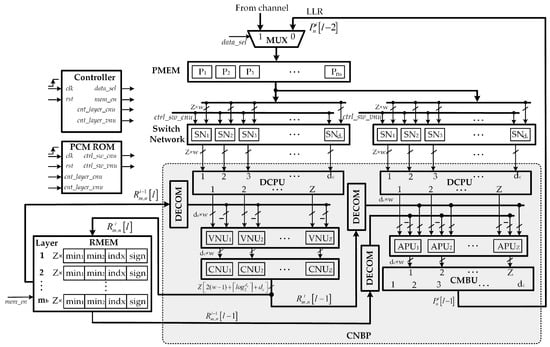
Figure 4.
Proposed overall low-complexity high-throughput pipelined layered QC-LDPC decoder architecture.
4.2. Memory Blocks
In our proposed architecture, two memory blocks are utilized, one for the input LLR values (PMEM) and one for the check to variable messages (RMEM). Assume that all input LLRs and exchanged messages are quantized on bits.
PMEM memory is implemented by an input register that stores the input LLR values (prior values) or posterior values from the previous layer. The memory is organized in register memory blocks, denotes by corresponding to the number of columns of the base matrix. Each register memory block consists of memory locations with bits of word-length, i.e., bits, and these stored 56 LLRs are read from register memory block in a single clock cycle. Thus, a total of bits of input memory is implemented in the proposed decoder.
RMEM memory is implemented as a dual port RAM, which stores compressed check to variable messages for all layers. With the proposed CNBP architecture, two minimum values of bit-width, a minimum index of bit-width , and -sign values are stored in RMEM for each decoding layer. Hence, a total of bits of RMEM memory is required for all CNBPs.
Therefore, the overall memory size used in our LDPC decoder is 92.512 kb.
4.3. Switch Network
A switch network (SN) is an Z-input, Z-output hardware structure that can put the input signals in the arbitrary order at the output. For the implementation of the QC-LDPC decoder, the switch network is an essential module. The proposed decoder consists of check node and variable node circular shift networks. Each of them consists of bit inputs and bit outputs. The barrel shifters are used to implement the cyclic shift permutations according to the shift values provided by the cyclic shifter controllers. In this decoder, the switch networks are implemented with -stage barrel shifters. There is no re-shuffling network in this architecture as we applied an H-matrix reformulation technique proposed in [33].
4.4. Variable Node Units
The proposed decoder consists of VNUs, which implement the variable node update step shown in Algorithm 1. The detailed architecture of a VNU in the proposed decoder is shown in Figure 5. Each VNU takes inputs at bit-width w LLR message and the check-to-variable node message from RMEM memory, i.e., . Each variable node message is computed by subtracting the corresponding check-to-variable node message from the LLR message, that is . This operation is implemented by a w-bit subtractor, hence the value outputted by the VNU is quantized on w bits.
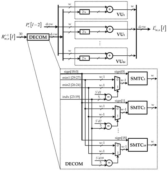
Figure 5.
Proposed variable node update unit architecture.
It should be noted that the check-to-variable node message is stored in RMEM as a message of bits. For a check node m, the corresponding message in format is given by the values , where denote the variable nodes connected to m. For a check node m, the corresponding message in format is given by the signs of the above messages, denoted by , their first and second minimum, denoted by and , and the index of the first minimum, denoted by . Figure 6 shows an message in decompressed and compressed format. Hence, the decompression unit DECOM aims at converting this compressed version of LLRs into extrinsic LLRs by using equalizers, MUXs and sign-magnitude to two’s complement conversion units (SMTCs) as shown in Figure 5.
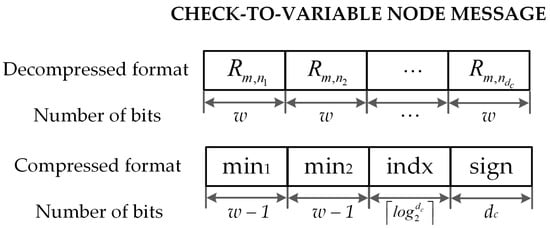
Figure 6.
Check-to-variable node message presents in decompressed and compressed format.
4.5. Check Node Units
The proposed decoder consists of CNUs, which implement the check node update step shown in Algorithm 1. A minimum-finder (19-FMVG) and sign processor unit (SPU) are exploited in this step. In this section, we focus on the computation of the first two minima , , and index of the first minimum since the signs of output messages can be simply calculated by XORing the adequate signs of input messages. The structure of the minimum-finder is based on the tree structure (TS) architecture proposed by Wey [34]. However, it is further modified in our proposed architecture so as to compute only the value and the index of the first minimum in the first clock cycle. The second minimum value is decided in the second clock cycle by re-utilizing the same hardware architecture.
The detailed architecture of a low complexity CNU is shown in Figure 7. As can be observed, the proposed CNU architecture consists of sign-magnitude conversion (SMC) units, a 19 inputs-first minimum value generator unit (19-FMVG), sign processor unit, and the compare and select (CS) unit for generating control signals. Initially, each CNU takes inputs with bit-width of value from the VNU. The 4-bit LLRs in the two’s complement format are converted into sign and magnitude format with the aid of sign-magnitude conversion (SMC) units. The control signal is set to either 0 or 1 to indicate the operation mode of the CNU. When is set to 0, i.e., the first clock cycle, the CNU is carried out to generate the first minimum and index of the first minimum . When is set to 1, i.e., the second clock cycle, the CNU is re-executed in order to calculate the second minimum value . When CNU in the second clock cycle, the maximum value of bit-width w is substituted for the input value at index instead of straightforwardly passed all input values to the 19-FMVG units. Moreover, depending upon the clock cycle being processed, the control signal is set to pass the corresponding minimum value to the output.
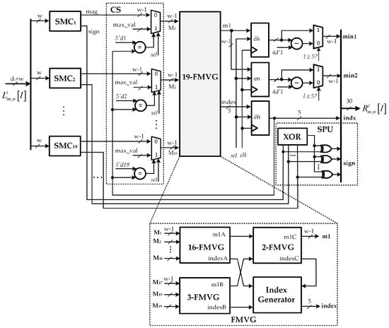
Figure 7.
Proposed check node unit (CNU) architecture.
The architecture of the FMVG for inputs is also presented in Figure 7. Since can be decomposed into the sum of 16 and 3, the result of -FMVG block is realized by combining corresponding blocks as described in [34]. The index generator block in Figure 7 is deployed to create the index of the first minimum value. The architecture of 3-FMVG is shown in Figure 8a. Moreover, the -FMVG block, which computes the value and the index of the first minimum among the input messages of bit-width w, can be constructed by cascading multiple 2-FMVGs as shown in Figure 8c. The 2-FMVG unit, as detailed in Figure 8b, is exploited for the comparisons discussed earlier. The comparison signal and output value of the 2-FMVG are defined as follows:
For the 19-FMVG block, an input word contains bits, then the comparator and MUX also require bits. In this section, we denote MUX as 1-bit 2-to-1 multiplexer, and MUX as a -bit 2-to-1 multiplexer. Table 4 summarizes the number of components required for the proposed minimum-finder based on FMVG and the conventional method, which determines both and values, denoted as two minimum values generator (TMVG). Results show that the proposed FMVG approach requires a much smaller number of comparisons and MUXs than the conventional method TMVG.
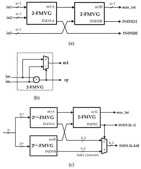
Figure 8.
Architecture of -first minimum value generator (FMVG) unit using the TS approach [34].
Table 4.
Components required for the minimum finders of inputs of bit-width .
4.6. A Posteriori Information Update Units
The proposed decoder consists of APUs, which implement the operations in a posteriori information update step shown in Algorithm 1. The detailed architecture of a low-complexity APU with only one adder array is shown in Figure 9. Each APU takes inputs at bit-width w and two values from check-to-variable node memory RMEM, i.e., and . Similarly, the control signal in the VNU is set to either 0 or 1 to indicate the operation mode. When is set to 0, i.e., the first clock cycle, the APU is carried out to calculate the sum of and . When is set to 1, i.e., the second clock cycle, the APU is re-executed in order to calculate by adding into the output from previous clock cycle. At the input, two MUXs are utilized to appropriately select the input data according to the clock cycle being processed. In addition, a deMUX is allocated at the output to indicate the truth output value of APU. Moreover, depending upon the clock cycle being processed, the control signal is sufficiently set to pass the computation result from the adder array to the output or feedback to the input multiplexer. All outputs from APUs are given to input multiplexers to start the processing of the next layer, as shown in Figure 4. As in the case of VNU architecture, the proposed APU uses two decompression units DECOM to convert the compressed LLRs taken from RMEM into decompressed extrinsic LLRs.
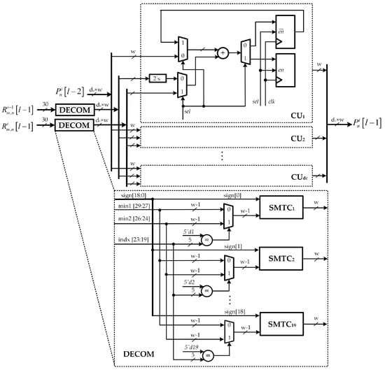
Figure 9.
Proposed a posteriori information update unit architecture.
4.7. Controller Block
This block generates control signals, such as to indicate the step being processed; and to indicate the layer being processed by CNUs, VNUs, and APUs; and , to enable write access to the check-to-variable node memory RMEM.
5. Implementation Results and Comparisons
The simulation of proposed low-complexity high-throughput pipelined layered QC-LDPC decoder architecture for 5G NR wireless standard was carried out using BPSK modulation in an AWGN channel environment. Figure 10 illustrates the FER performance of the proposed QC-LDPC decoders on the , for BG1 base matrix of 5G NR wireless standard. The results indicate that the proposed QC-LDPC decoder architecture scheme with bit-width and ten decoding iterations deliver a FER of 10 at 2.75 dB. It can be observed that the CMS decoding provides a better error correction performance compared with the original MS and OMS algorithms.
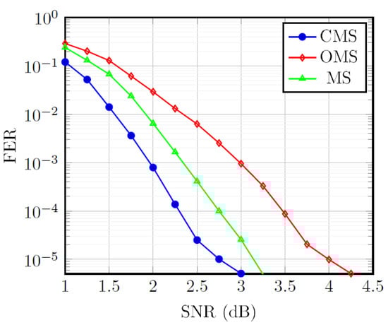
Figure 10.
Decoding performance of the QC-LDPC decoders on the , for base matrix BG1 of 5G NR.
The major advantage to be realized from our proposed design comes at the decoder complexity reduction. It should be noted that more clock cycles are required to finish a decoding iteration compared to the conventional design. By applying the hardware reuse approach, the critical path is reduced, and, therefore, the operating frequency is enhanced. Hence, the throughput would remain the same in the case of an ideal clock frequency. The reported throughput is given by Equation (6), where denotes the maximum operating frequency, and is the maximum number of iterations to decode one codeword. Based on the pipeline chart in Figure 11, the number of clock cycles per decoding iteration is in which two clock cycles are required to decode each layer. The proposed decoder consumes a total of clock cycles.
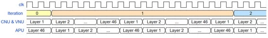
Figure 11.
Pipeline schedule of the proposed QC-LDPC decoder.
In order to confirm the efficiency of our solution, we have conducted our proposed decoder on the expansion size Z = 56, code rate using 5G base matrix BG1 LDPC code. The proposed LDPC decoder architecture was modeled by the Verilog hardware description language (HDL) and simulated to verify its functionality using a test pattern generated from a C simulator. After successful verification of the design functions, it was then synthesized using sufficient time and area constraints. Both simulation and synthesis steps were executed by using Synopsys design tools and TSMC 65-nm CMOS standard cell technology. The post-synthesis results are reported in Table 5. The proposed low complexity layered LDPC decoder architecture occupies an area of 1.49 mm and achieves a throughput of 3.04 Gbps at 750 MHz. The power and energy dissipations are 259 mW and 85.20 pJ/bit, respectively.
In addition, Table 5 shows the implementation and performance comparisons of the proposed low-complexity high-throughput decoder with various other LDPC decoders. It is confirmed that the proposed design helps reduce the decoder complexity. Since these designs have different implementation parameters, including code length, CMOS technology, and the quantization bits, it is necessary to apply performance normalization for a fair comparison. The normalization method in [35] is adopted. In order to keep the hardware performance comparison on an equal basis with respect to technology, area, and the number of iterations, it is usually evaluated by the throughput-to-area ratio (TAR) metric, which was defined by TAR = Throughput/Area (Gbps/mm). It can be observed that the proposed architecture is found to be the most efficient in terms of area efficiency among the reported decoders, yielding a normalized throughput-to-area ratio (NTAR) value of 2.04 Gbps/mm. Specifically, the NTAR of our work is 10.3% better than that of the next most efficient decoder [36] and 38.7% better than the rest of the reported decoders. The decoder in [37], which offers the highest normalized throughput at 7.31 Gbps, occupies a very large-scale design area. Hence, its NTAR is significantly low compared to our proposed design. Specifically, the NTAR ratio of our work is about 46.08% better than that of [37].
Table 5.
Implementation and comparison for 5G QC-LDPC decoders.
Table 5.
Implementation and comparison for 5G QC-LDPC decoders.
| Design | Proposed | [37] | [38] | [36] |
|---|---|---|---|---|
| Standard | 5G-NR | 802.15.3c | 802.11n | 802.16e |
| CMOS technology | 65-nm | 90-nm | 90-nm | 90-nm |
| LDPC code | irregular | regular | irregular | irregular |
| Scheduling | layered | layered | layered | layered |
| Decoding algorithm | CMS | NMS | MS | NMS |
| Submatrix size | 56 | 21 | 81 | 96 |
| Code length | 3808 | 672 | 1944 | 2304 |
| Code rate | 1/3 | 1/2 | 1/2 | 1/2 |
| Bit-width (bits) | 4 | 4 | 4 | 6 |
| Max. iterations | 10 | 5 | 10 | 10 |
| Frequency (MHz) | 750 | 157 | 555 | 950 |
| Memory (Kb) | 92.512 | 6.93 | - | 87.752 |
| Area (mm) | 1.49 | 2.25 | 4.88 | 2.90 |
| Norm. Area (mm) | 1.49 | 6.65 | 4.99 | 1.67 |
| Throughput (Gbps) | 3.04 | 5.28 | 4.5 | 2.20 |
| Norm. Throughput (Gbps) | 3.04 | 7.31 | 6.23 | 3.05 |
| Power (mW) | 259 | 182 | 523 | 870 |
| Energy effic. (pJ/bit) | 85.20 | 34.47 | 116.22 | 395.45 |
| Norm. Energy effic. (pJ/bit) | 85.20 | 24.90 | 83.95 | 285.25 |
| TAR (Gbps/mm) | 2.04 | 2.35 | 0.92 | 0.76 |
| NTAR (Gbps/mm) | 2.04 | 1.10 | 1.25 | 1.83 |
† NTAR = Norm. Throughput/Norm. Area.
High operating frequency usually comes at the cost of increased power consumption. Despite this, though, as shown in Table 5, the proposed enhanced decoder achieves very good results in terms of energy efficiency, very close to that of the work presented in [38]. Moreover, it can be seen that the energy efficiency of our proposed LDPC decoder yields 70.13% better than that of the next most area-efficient decoder in [36].
Based on the implementation results presented above, it is clear that the design method offers a significantly low complexity, high area efficiency, and high throughput, which is sufficient for the 5G NR wireless communication standard. However, it is very challenging to design a low error correction decoder for 5G LDPC codes since the offset factor is relatively difficult to optimize in quantized LDPC decoders. In order to improve the error correction performance as well as achieve cost efficiency and high throughput issues, further enhancements should be proposed in future research for adjusting the offset factor of the OMS decoder in the pure LDPC part.
6. Conclusions
Enhanced versions of CNBP architectures are proposed to improve the complexity of the LDPC decoders in this paper. First, an efficient minimum-finder for CNU architecture that reduces the hardware required for the computation of the first two minima and a low complexity a posteriori information update unit architecture, which only requires one adder array for their operations are introduced. Finally, an area-efficient pipelined layered QC-LDPC decoder architecture for 5G NR communication systems is described in detail. Simulation results show that the proposed architecture achieves low complexity and high throughput compared to other QC-LDPC architectures available in the literature. Therefore, the proposed QC-LDPC decoder can be applied in 5G NR wireless communication standard applications.
Author Contributions
T.T.B.N. conceptualized the idea of this research, conducted experiments, collected data, and prepared the original version. T.N.T. reviewed, analyzed data, and updated the manuscript. H.L. supervised, validated, reviewed, and supported the research with funding. All authors have read and agreed to the published version of the manuscript.
Funding
This research received no external funding.
Acknowledgments
This work was supported by the NRF grant funded by the Korea government (MIST) (No. 2020M3H2A1076786), in part by the BK 21 Four Program funded by the Ministry of Education(MOE, Korea) and NRF, and in part by the KEIT grant funded by the MOTIE, Korea (No. 20010589).
Conflicts of Interest
The authors declare no conflict of interest.
References
- Gallager, R.G. Low-density Parity-check Codes. IRE Trans. Inform. Theory 1962, 8, 21–28. [Google Scholar] [CrossRef]
- MacKay, D.J.; Neal, R.M. Near Shannon Limit Performance of Low-density Parity-check Codes. Electron. Lett. 1996, 32, 1645–1646. [Google Scholar] [CrossRef]
- Shannon, C.E. A Mathematical Theory of Communication. Bell Syst. Tech. J. 1948, 27, 379–423. [Google Scholar] [CrossRef]
- Tanner, R.M. A Recursive Approach to Low Complexity Codes. IEEE Trans. Inf. Theory 1981, 27, 533–547. [Google Scholar] [CrossRef]
- Wymeersch, H. Iterative Receiver Design; Cambridge University Press: Cambridge, UK, 2007. [Google Scholar]
- Ryan, W.; Lin, S. Channel Codes: Classical and Modern; Cambridge University Press: Cambridge, UK, 2009. [Google Scholar]
- Rovini, M.; Insalata, N.E.; Rossi, F.; Fanucci, L. VLSI Design of a High Throughput Multi-rate Decoder for Structured LDPC Codes. In Proceedings of the 8th Euromicro Conference on Digital System Design (DSD’05), Porto, Portugal, 30 August–3 September 2005; pp. 202–209. [Google Scholar]
- Lu, J.; Moura, J.M. Structured LDPC Codes for High-density Recording: Large Girth and Low Error Floor. IEEE Trans. Magn. 2006, 42, 208–213. [Google Scholar] [CrossRef]
- Richardson, T.J.; Shokrollahi, M.A.; Urbanke, R.L. Design of Capacity-approaching Irregular Low-density Parity-check Codes. IEEE Trans. Inf. Theory 2001, 47, 619–637. [Google Scholar] [CrossRef]
- Part 16: Air Interface for Fixed and Mobile Broadband Wireless Access Systems, IEEE 802.16e; IEEE Standard Association: Piscataway, NJ, USA, 2008.
- A 802.11 Wireless LANs, TGn Sync Proposal Technical Specification; IEEE Standard Association: Piscataway, NJ, USA, 2004.
- A 802.11 Wireless LANs, WWiSE proposal: High Throughput Extension to the 802.11 Standard; IEEE Standard Association: Piscataway, NJ, USA, 2005.
- Part 11: Wireless LAN Medium Access Control (MAC) and Physical Layer (PHY) Specifications, 802.11ad-2012; IEEE Standard Association: Piscataway, NJ, USA, 2012.
- Session Chairman (Nokia). Chairman’s Notes of Agenda Item 7.1.5 Channel Coding and Modulation. 3GPP TSG RAN WG1 Meeting No. 87, R1-1613710. 2016. Available online: https://portal.3gpp.org/ngppapp/CreateTdoc.aspx?mode=view&contributionId=752413 (accessed on 20 February 2021).
- Ad-Hoc Chair (Nokia). Chairman’s Notes of Agenda Item 7.1.4. Channel Coding. 3GPP TSG RAN WG1 Meeting AH 2, R1-1711982. 2017. Available online: https://portal.3gpp.org/ngppapp/CreateTdoc.aspx?mode=view&contributionId=805088 (accessed on 20 February 2021).
- Richardson, T.; Kudekar, S. Design of Low-Density Parity Check Codes for 5G New Radio. IEEE Commun. Mag. 2018, 56, 28–34. [Google Scholar] [CrossRef]
- Li, H.; Bai, B.; Mu, X.; Zhang, J.; Xu, H. Algebra-assisted Construction of Quasi-cyclic LDPC Codes for 5G New Radio. IEEE Access 2018, 6, 50229–50244. [Google Scholar] [CrossRef]
- Fan, J.L. Constrained Coding and Soft Iterative Decoding; Springer: Boston, MA, USA, 2001; pp. 195–203. [Google Scholar]
- Kou, Y.; Xu, J.; Tang, H.; Lin, S.; Abdel-Ghaffar, K. On Circulant Low-density Parity-check Codes. In Proceedings of the IEEE International Symposium on Information Theory, Lausanne, Switzerland, 30 June–5 July 2002; p. 200. [Google Scholar]
- Li, Z.; Kumar, B. A Class of Good Quasi-cyclic Low-density Parity Check Codes Based on Progressive Edge Growth Graph. In Proceedings of the Conference Record of the Thirty-Eighth Asilomar Conference on in Signals, Systems and Computers, Pacific Grove, CA, USA, 7–10 November 2004; pp. 1990–1994. [Google Scholar]
- Sha, J.; Wang, Z.; Gao, M.; Li, L. Multi-Gb/s LDPC Code Design and Implementation. IEEE Trans. Very Large Scale Integr. (VLSI) Syst. 2009, 17, 262–268. [Google Scholar]
- Sha, J.; Gao, M.; Zhang, Z.; Li, L.; Wang, Z. Efficient Decoder Implementation for QC-LDPC Codes. In Proceedings of the 2006 International Conference on in Communications, Circuits and Systems, Guilin, China, 25–28 June 2006; pp. 2498–2502. [Google Scholar]
- Masera, G.; Quaglio, F.; Vacca, F. Implementation of a Flexible LDPC Decoder. IEEE Trans. Circuits Syst. II: Express Briefs 2007, 54, 542–546. [Google Scholar] [CrossRef]
- Sun, Y.; Karkooti, M.; Cavallaro, J.R. VLSI Decoder Architecture for High Throughput, Variable Block-size and Multi-rate LDPC Codes. In Proceedings of the 2007 IEEE International Symposium on Circuits and Systems, New Orleans, LA, USA, 27–30 May 2007; pp. 2104–2107. [Google Scholar]
- Zhong, H.; Zhang, T. Block-LDPC: A Practical LDPC Coding System Design Approach. IEEE Trans. Circuits Syst. Regul. Pap. 2005, 52, 766–775. [Google Scholar] [CrossRef]
- Mansour, M.M.; Shanbhag, N.R. High-throughput LDPC Decoders. IEEE Trans. Very Large Scale Integr. (VLSI) Syst. 2003, 11, 976–996. [Google Scholar] [CrossRef]
- Study on New Radio Access Technology Physical Layer Aspects. TR 38.802, 3GPP. 2017. Available online: https://portal.3gpp.org/desktopmodules/Specifications/SpecificationDetails.aspx?specificationId=3066 (accessed on 20 February 2021).
- NTT Docomo Inc. New SID Proposal: Study on New Radio Access Technology. 3GPP TSG RAN Meeting No.71, RP-160671. 2016. Available online: https://www.3gpp.org/DynaReport/TDocExMtg--RP-71--31637.htm (accessed on 20 February 2021).
- Fossorier, M.P.C. Quasi-cyclic Low-density Parity-check Codes from Circulant Permutation Matrices. IEEE Trans. Inf. Theory 2004, 50, 1788–1793. [Google Scholar] [CrossRef]
- Tang, H.; Xu, J.; Kou, Y.; Lin, S.; Abdel-Ghaffar, K. On Algebraic Construction of Gallager and Circulant Low-density Parity-check Codes. IEEE Trans. Inf. Theory 2004, 50, 1269–1279. [Google Scholar] [CrossRef]
- Chen, L.; Xu, J.; Djurdjevic, I.; Lin, S. Near-Shannon-limit Quasi-cyclic Low-density Parity-check Codes. IEEE Trans. Commun. 2004, 52, 1038–1042. [Google Scholar] [CrossRef]
- Chen, T.; Vakilinia, K.; Divsalar, D.; Wesel, R.D. Protograph-based Raptor-like LDPC Codes. IEEE Trans. Commun. 2005, 63, 1522–1532. [Google Scholar] [CrossRef]
- Kim, S.; Sobelman, G.E.; Lee, H. A Reduced-complexity Architecture for LDPC Layered Decoding Schemes. IEEE Trans. Very Large Scale Integr. (VLSI) Syst. 2001, 19, 1099–1103. [Google Scholar] [CrossRef]
- Wey, C.-L.; Shieh, M.-D.; Lin, S.-Y. Algorithms of Finding the First Two Minimum Values and Their Hardware Implementation. IEEE Trans. Circuits Syst. Regul. Pap. 2008, 55, 3430–3437. [Google Scholar]
- Chen, C.; Lin, Y.; Chang, H.; Lee, C. A 2.37-Gb/s 284.8 mw Rate Compatible (491,3,6) LDPC-CC Decoder. IEEE J. Solid-State Circuits 2012, 47, 817–831. [Google Scholar] [CrossRef]
- Zhang, K.; Huang, X.; Wang, Z. High-throughput Layered Decoder Implementation for Quasi-cyclic LDPC Codes. IEEE J. Sel. Commun. 2009, 27, 985–994. [Google Scholar] [CrossRef]
- Li, M.; Yang, C.; Ueng, Y. A 5.28-Gb/s LDPC Decoder with Time-domain Signal Processing for IEEE 802.15.3c Applications. IEEE J. Solid-State Circuits 2017, 52, 592–604. [Google Scholar] [CrossRef]
- Tsatsaragkos, I.; Paliouras, V. A Reconfigurable LDPC Decoder Optimized for 802.11n/ac Applications. IEEE Trans. Very Large Scale Integr. (VLSI) Syst. 2018, 26, 182–195. [Google Scholar] [CrossRef]


Publisher’s Note: MDPI stays neutral with regard to jurisdictional claims in published maps and institutional affiliations. |
© 2021 by the authors. Licensee MDPI, Basel, Switzerland. This article is an open access article distributed under the terms and conditions of the Creative Commons Attribution (CC BY) license (http://creativecommons.org/licenses/by/4.0/).