1. Introduction
Digital predistortion (DPD) is a widely used technique to improve the linearity performance of a power amplifier (PA) at radio–frequency (RF), and it is increasingly becoming a fundamental part of the RF transmitting system. In recent years, more advanced PA topologies are being adopted for improved power efficiency, e.g., load- and supply-modulated PAs, or PA arrays, which inevitably introduce higher levels of distortion [
1,
2,
3,
4,
5,
6]. Moreover, PAs for microwave and millimeter-wave applications are nowadays implemented in Gallium Nitride (GaN) technology, which is affected by spurious dispersive phenomena causing peculiar behaviors like soft compression and long-term memory effects [
7,
8,
9]. Indeed, the continuous push for broadband operation will incrementally expose to the presence of nonlinear dynamic effects [
10]. Hence, novel PA modeling and linearization approaches must be envisioned [
11,
12,
13,
14,
15].
In particular, DPD model formulation and coefficient identification techniques play a key role in the overall performance of the transmitter. Two main measurement-based identification methods are commonly adopted: the indirect learning architecture (ILA) [
16,
17] and the direct learning architecture (DLA) [
18]. In the ILA, shown in
Figure 1a, a postinverse model of the PA is identified, and its coefficients are then copied for the predistorter. This method, which leverages on a straightforward linear least-square estimation, is based on the assumption that the postinverse model of the PA is identical to its preinverse [
19]. In the DLA, shown in
Figure 1b, the predistorter is directly identified from PA stimulus–response pairs. In this case, the identification of the preinverse is obtained from a preliminary identification of the forward PA model, and from the subsequent model inversion. However, given the presence of nonlinear dynamic effects, such identification is often not trivial. In fact, the forward model inversion is usually achieved by means of nonlinear optimization algorithms [
18].
Both DLA and ILA architectures can also be implemented using adaptive iterative procedures involving multiple acquisitions, which might allow for the convergence to an improved set of DPD coefficients [
20,
21]. In this context, it is worth mentioning an alternative architecture referred to as iterative learning control (ILC) [
22,
23]. With ILC, the optimum predistorted signal is obtained at first (
Figure 2a), while the identification of the actual parametric predistorter is performed in a subsequent step (
Figure 2b). The first step involves the iterative identification of the predistorted signal in a non-parametric way, meaning that the algorithm does not directly target the DPD coefficients but the optimum input signal realizing the desired output. Despite requiring an increased number of measurements (one for each iteration), this approach allows for a model-independent solution. In the second step, the DPD coefficients can be eventually identified from the optimal input signal.
For all the mentioned architectures, the learning procedure only accounts for one single figure-of-merit (FoM), i.e., a linearity FoM, usually the time-domain normalized mean squared error (NMSE) between the actual and desired output signals. Indeed, these architectures can be generally seen as implementing unconstrained optimization, NMSE minimization being the only target. Indeed, this classical approach allows for operating linearly yet under deeper compression (i.e., with higher power efficiency), already enhancing the overall PA behavior with respect to the un-predistorted case. However, there is no guarantee that DPD will actually result in the best global PA performance achievable for the specifications of a given modulation standard. For example, there is no controlled way to limit the linearity performance up to a prescribed and sufficient level, although such a control would be useful to make room for maximizing another PA FoM of interest, e.g., the RF output power or power efficiency. In this context, it is reasonable to assume that multi-objective optimization approaches could deliver a better compromise among the conflicting PA specifications.
In this work, we propose a novel DLA-based DPD identification approach aimed at optimizing one (possibly, more than one) PA FoM, yet respecting a constraint. To this aim, we adopt the general architecture in
Figure 3, leveraging on an iterative optimization routine. In particular, we implement a flexible constrained optimization algorithm capable of steering the learning process towards the desired joint optimum. This work is among the first ones [
24,
25,
26] using multi-objective optimization for coefficients identification, while keeping a predetermined pre-inverse formulation and fixed model order.
The article is organized as follows:
Section 2 describes in detail the proposed multi-objective algorithm.
Section 3 reports the implementation of the algorithm in the case of a constrained optimization, showing the linearization of a GaN PA by maximizing the RF output power (hence, efficiency), yet respecting a prescribed linearity constraint. Conclusions are drawn in
Section 4.
2. Multi-Objective DPD Optimization
Let us consider a predistorter to be implemented with a generic linear-in-the-parameters model. Labeling
and
as the input and output respectively (
Figure 3), the generic predistorter structure can be expressed as
where
are the model coefficients and
are suitable non-analytic functions of the past values of the complex signal
, up to a memory duration
M. The specific form of each function is fixed by the adopted model structure, with multivariate polynomials being particularly used in DPD applications [
17]. As the nonlinear functions are pre-determined, the model can be fully identified once the coefficients
are known. In this respect, Equation (
1) can be recast in matrix form as
where the following vector notation is introduced:
Differently from the ILA approach, in which Equation (
2) is directly solved for the coefficients of the postdistorter from the input–output measurements, the strategy adopted in this work leverages on a DLA identification of the coefficients in order to jointly optimize different performance metrics. Indeed, for the PA under test, all of the FoMs of interest are a function of the applied input signal
and, ultimately, for a fixed reference
, depend just on the predistortercoefficients
through Equation (
2).
Multi-objective optimization techniques have the goal of identifying Pareto-optimal solutions for
[
24], in which no single objective can be improved without making at least another objective worse. This type of trade-off is commonly encountered in PA design, as an increase in linearity due to predistortion is usually accompanied by a reduction in the output power.
In this framework, standard DPD approaches can be seen as optimization of just a single linearity FoM, without taking explicitly into account output power or other (e.g., efficiency) metrics. Instead, in this work, we address the case where two objective functions f and g correspond to two conflicting PA specifications which are to be jointly optimized. In particular, we take g to represent a waveform linearity constraint while f corresponds to another conflicting performance metric, such as output power.
The general multi-objective optimization problem can be equivalently recast as a series of successive constrained optimizations [
27], in which a single objective is maximized using standard methods, while fixed constraints are imposed on all the other objectives. In this case,
is taken to be the objective function to be maximized, and
as the constrained one. Then, the following optimization problem must be solved:
where
is a scalar quantity, representing the maximum allowable value for the constraint
g. The solution to this problem explores just a single trade-off point between the two FoMs of interest. The full Pareto front of optimal solutions can then be explored by increasing or reducing the value of
and running the corresponding constrained optimization, in order to reconstruct the compromise between the two metrics under examination.
The constrained optimization algorithm proposed in this work for the solution of (
6) is depicted in the flowchart in
Figure 4. As a first step, if the constraint is not satisfied (
), an optimization direction
(relevant to the constraint
g) must be obtained to resolve the next iteration.
In the proposed algorithm, the calculation of
follows the first step of the ILC approach by minimizing the instantaneous complex error between the (scaled) desired signal
and the measured output signal
:
Such a minimization can be achieved by an iterative procedure based on the Newton’s method [
22], where the optimized PA input at the
ith iteration is found as:
where
is a matrix containing the values of the instantaneous gain for each acquired sample
:
The gain matrix in (
9) represents a first-order approximation of the Jacobian matrix as required by the Newton’s method. However, other choices for
could also be adopted, e.g., a fixed value matrix or a finite-difference approximation of the Jacobian. While the former could provide a more stable convergence of the iterative procedure, the latter could speed-up the algorithm at the cost of an higher number of function evaluations (i.e., measurements) at each iteration, necessary for the calculation of the finite differences.
In this work, differently from the classical ILC,
should be defined with respect to the coefficients
. Then, we express the
in terms of
and
by inverting the matrix form in (
2), obtaining
being the pseudoinverse of
. By substituting this expression in (
8), the formula for the
ith iteration and the relative direction results in:
where the step size
is bisected until the constraint function
g is improved, i.e.,
. The progressive reduction of
avoids overshoots, while improving the verification of the constraint. As soon as the constraint is satisfied, the next iteration goes towards the maximization of
f.
For this second function, the optimization is based on a gradient descent:
where the gradient, corresponding to the optimization direction
, is obtained by measuring a finite-differences approximation. The choice of a gradient-based approach for targeting the optimum allows for the maximum convergence speed in terms of number of iterations. However, it should be noted that estimating the partial derivatives requires two function evaluations for each complex DPD coefficient to be optimized. Therefore, an excessive number of DPD coefficient might offset the relatively low number of iterations. In Equation (
12), the step size
is bisected until
f improves, i.e.,
, provided that the constraint remains valid. Indeed, depending on the regularity of the function to optimize, the gradient descent might not always identify the optimum direction. Hence, the progressive reduction of
drives the method to a smoother convergence, while avoiding excessive oscillating behavior.
As far as the practical evaluation of the achieved optimum is concerned, it should be noted that the considered optimization aims at finding the maximum point of an unknown, possibly non-convex function. In this case, the definition of the stopping criteria is not trivial, considering that it is not possible to define a precise metric measuring the degree of global optimality [
28]. Given these premises, the following approach is followed. As long as
f is improved and
satisfied, the algorithm evaluates a tolerance threshold
. When exceeded, this threshold indicates that no further improvement is available for
f, triggering the exit condition. Possible additional exit conditions, which can be combined with the main one, include reaching a maximum number of iterations (
) or function evaluations (
).
3. Measurement Results
While many different trade-offs could be considered [
24], in this work, we have chosen the PA average RF output power and the linearity as conflicting FoMs. The average RF output power will correspond to the function to be maximized (
f):
where BW is the signal bandwidth,
is the spectrum of the measured output signal, and
is the matched-PA load resistance. The linearity constraint (
g) will be weighted by imposing a maximum limit to one of the following FoM, i.e., the Adjacent Channel Power Ratio (ACPR), or the NMSE:
where SB stands for side-band,
is the desired output,
is the measured output, and
is the complex desired gain. Contrary to the ILA case, the proposed method does not fix an a priori value for
, which remains a degree of freedom for the optimization method.
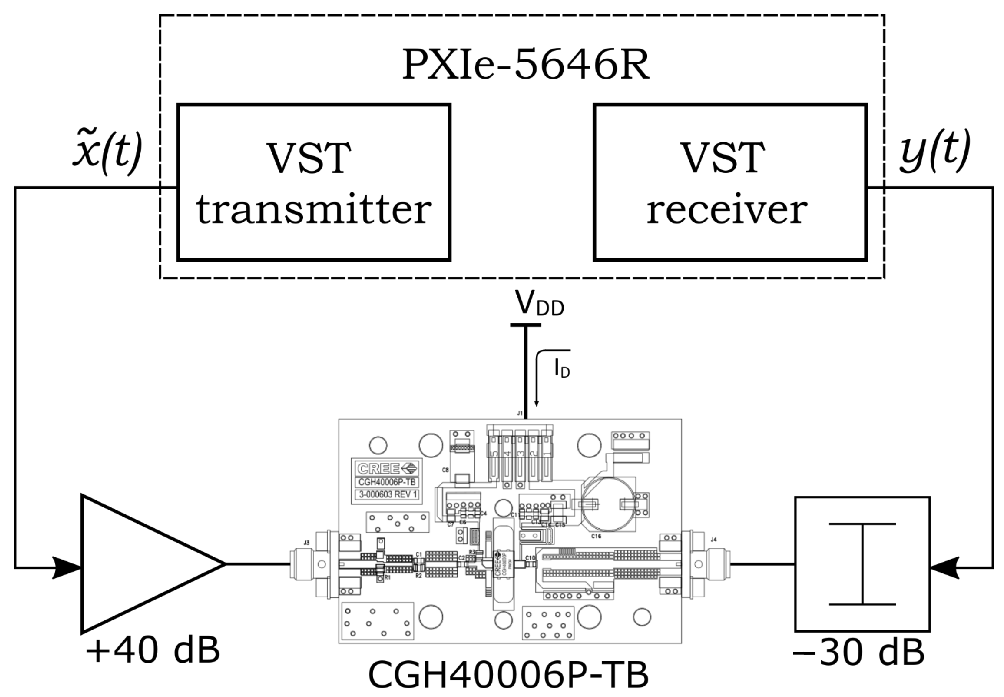
The approach has been applied by means of the remote setup in Landin et al. [
29]. Such a setup is based on a single benchtop instrument, the PXIe-5646R Vector Signal Transceiver (VST) by NI, featuring 200-MHz instantaneous bandwidth. With this setup, whose block diagram is shown in
Figure 5, the user can set the baseband input signal using the vector signal generator within the VST, and measure the baseband output signal from the VST receiver, with a sample rate of
MSa/s for both input and output. The DUT is the cascade of a 40-dB linear driver amplifier and a GaN PA (Cree CGH40006-TB) biased in class-AB at 100 mA, operating at 2-GHz carrier frequency. The output of the PA is attenuated by 30 dB before reaching the VST receiver.
The adopted input signal is a random-phase 2 k-tone with 20-MHz bandwidth and peak-to-average power ratio (PAPR) of ≃9 dB, resulting in
k samples for each acquisition, while the predistorter is described by a classical MP model formulation:
where
are the DPD coefficients,
K is the nonlinearity order, and
M is the memory depth. The model in Equation (
15) can be written in matrix form as in Equation (
2), where
corresponds to:
N being the total number of samples.
Throughout this work, K and M are predetermined and fixed values chosen as and , which are not subject to optimization. This preliminary selection is performed by successively increasing the model order until the DPD (using ILA) achieved a sufficiently low NMSE (≃−30 dB), resulting in a reasonable compromise between the necessary model complexity and the avoidance of over-fitting issues.
In addition, the total number of coefficients (
) is compatible with the dimensionality to be managed by the optimization algorithm in
Section 2. However, the algorithm itself does not depend on the specific predistorter model, and it could be seamlessly used with other linear-in-the-parameters formulations, provided that a reasonably low number of DPD coefficients is considered.
Two separate datasets of signal realizations are acquired, one used for model coefficient learning by means of the optimization algorithm in
Figure 4, and the other for DPD validation.
Figure 6a,b report the linearization results when the ACPR (
Figure 6a) and the NMSE (
Figure 6b) are used as constraints within the algorithm. The blue curves represent the proposed multi-objective optimization results, obtained by sweeping the constraint value (
) for the ACPR (
Figure 6a) and the NMSE (
Figure 6b). The curves for the ILA case (red) are obtained by sweeping the target linearization gain, which is the only control variable in the ILA architecture. The linearization gain is swept up to an input signal peak power of −8 dBm, which corresponds to the maximum available power by the vector signal generator within the VST [
29]. The black curves correspond to the non-predistorted case at different input powers.
For both cases, the curve obtained with the proposed multi-objective algorithm lays closer to the —linearity optimum, substantially outperforming the classical ILA architecture for intermediate linearity levels (i.e., −35 to −33 dB of ACPR, or −27.5 to −23 dB of NMSE), yet using the same number of DPD coefficients. This demonstrates that the classical ILA method, which only accounts for linearity by NSME minimization and does not embed capabilities for Pareto front exploration, delivers inferior PA global performance. At the same time, for small values of ACPR and NMSE (i.e., high-linearity), the fundamental trade-off between linearity and RF output power gets increasingly narrow, so that no space for improvement is left for the output power maximization capability of the multi-objective approach. In this case, both methods will tend to show similar performance.
Figure 7a compares the acquired output spectra relative to the two different DPD configurations, as well as the case of the un-predistorted PA, for the same level of ACPR ≃−33 dB. It can be clearly seen that, while the linearity performance is nearly the same for the three cases, the RF output power is maximum for the multi-objective DPD (corresponding to an average RF output power of 0.8 W), providing up to 14%
improvement with respect to ILA (
W), whereas it is much smaller for the un-predistorted PA. In
Figure 7b, instead, the three situations are shown for the same level of RF average output power (
W), showing a better linearity performance for the multi-objective case (ACPR = −34 dB versus ACPR = −33 dB for ILA). For reference purposes,
Figure 7 also includes the maximum output power performance without DPD at −4 dB compression (
1.3 W, ACPR ≃−26.5 dB). Given the high level of distortion involved, this case falls out of the trade-off representation shown in
Figure 6.
The same performance can also be observed in the instantaneous gain characteristics shown in
Figure 8a,b, corresponding to
Figure 7a,b, respectively. The PA is effectively linearized at a 4-dB compression point, with the multi-objective optimization further improving the performance in terms of RF output power. For completeness,
Figure 9a,b show the corresponding instantaneous AM/AM characteristics.
Finally,
Figure 10a reports the iterative behavior of the algorithm, highlighting the dynamic change of the optimization direction between the one kept to maintain the ACPR below the limit (
), imposed using the instantaneous gain normalization, and the one for maximizing
(
) by gradient descent.
Figure 10b reports the same iterative trajectory of
Figure 10a in the same domain as
Figure 6. It can be seen that the found optimum can be reached within a limited number of iterations.
4. Conclusions
The proposed multi-objective optimization method allows for exploring the trade-off between linearity and RF output power of a PA, resulting in a generalized DPD approach that can better enhance the global performance with respect to the classical ILA-based DPD. In particular, this is obtained by constraining one PA metric, and concurrently maximizing another one in an iterative fashion, eventually resulting in a tailored control of the predistorted input. Despite the impossibility to assess if the achieved maximization actually intercepts the global optimum of the complex multidimensional object function linking the FoMs with the DPD coefficients, the reached solution effectively delivers improved performance with respect to the classical ILA-based, single-objective DPD.
It is worth highlighting that this improvement just derives from the application of a different learning algorithm for the identification of the DPD coefficients, and that the same fixed DPD model order is used in all cases. Therefore, adopting this technique does not require any change in the DPD system configuration, nor any additional hardware.
The method should be seamlessly applicable in other test conditions and using different FoMs. As an example, a preliminary simulation-based evaluation of the trade-off between linearity and efficiency in supply-modulated PAs is reported in Mengozzi et al. [
30]. Moreover, the proposed optimization framework is promising for the synthesis of optimal input signals of next generation multiple-input transmitters, including PA arrays or load-modulated amplifiers [
5,
11]. Indeed, when multiple digitally-controlled inputs are involved, many different combinations of the inputs could reach a given performance metric, implying non-trivial preinverse identification and, possibly, sub-optimal performance. In this context, the proposed optimization framework can provide a useful numerical solution to exploit the higher dimensionality of multi-input systems. Future work will also include the enhancement of the method by combining PA incremental modeling techniques [
31] to minimize the measurement burden.

 ,
, 


