Article

Impact of Absorbers on the Shielding Effectiveness of Metallic Rooms with Apertures

1
Radio & Satellite Research Division, Electronics and Telecommunications Research Institute, Daejeon 34129, Korea
2
School of Electrical and Electronic Engineering, The University of Suwon, Hwaseong 18323, Korea
*
Author to whom correspondence should be addressed.
Electronics 2021, 10(3), 237; https://doi.org/10.3390/electronics10030237
Submission received: 22 December 2020 / Revised: 15 January 2021 / Accepted: 18 January 2021 / Published: 21 January 2021
(This article belongs to the Section Microwave and Wireless Communications)

Abstract

:
An electromagnetic field penetrating through an aperture or slot of a metallic enclosure generates many standing-waves due to the resonance inside the metallic enclosure, which results in reduced shielding performance. This paper examines the effect of absorbent material (absorber) to improve shielding effectiveness (SE) of large metallic rooms with apertures or slots. First, a theoretical formulation to extract the Q-factor of an absorber with any shape is proposed. Using this, the contribution of the absorber to the SE improvement of a shielded room with different sized circular apertures was investigated. Second, the resonant mode density inside the shielded room was classified into non-resonant, under-moded, and over-moded states with an increase in frequency, and the effect of the absorber in each frequency range was examined. The analysis was conducted through numerical simulation using a commercial full-wave simulator and experimental measurement using a fabricated actual shielded room and commercial absorbers. The accuracy of the analysis results was verified through the comparison of simulated and measured results. The analysis results ensured that the absorber was not effective in improving the SE in the non-resonant state of the metallic room. It was also confirmed that the absorber was effective in improving the SE in the over-moded state of the metallic room where a severe standing-wave occurs. In addition, the SE improvement level differed depending on the location of the absorber in the room.

1. Introduction

Generally, metallic enclosures have been used in order to electromagnetically shield and mechanically protect the interior equipment and systems from unintentional and intentional electromagnetic fields such as unwanted noises and electromagnetic pulses [1,2,3]. The shielding effectiveness (SE) that represents the shielding performance of the metallic enclosures is determined by three effects, as illustrated in Figure 1 and Equation (1). The first one is material effects, and the other two are structural effects. If the material’s thickness is not greater than its skin depth, the electromagnetic field, especially the magnetic field, can penetrate through the material [4]. Therefore, the material effects are determined by the thickness and the two material properties of conductivity and permeability. They should be considered in the shielding of a magnetic field at a low-frequency range. To analyze this diffusion effect, we can simply use analytic solutions [5,6] or numerical simulation [7].
The second is the leakage effect of apertures or slots on the surface of metallic enclosures. In practical situations, the holes or seams of various shapes are inevitable parts of the enclosure for air ventilation, doors for access, cabling and so on. As large enclosures such as shielded rooms age over time, unwanted seams or gaps may occur. The shielding performance of the enclosures for protecting critical equipment and systems against external electromagnetic fields is compromised by these apertures and holes. To completely protect from electromagnetic penetration, the apertures and slots on the metallic enclosures should be properly handled and managed by using various gasket components [8,9,10]. Until now, the electromagnetic coupling mechanism through apertures on the metallic enclosure has been widely investigated by using analytical, numerical and experimental analyses to minimize the effect of apertures on shielding properties [11,12]. In order to increase the shielding performance of an enclosure without compromising the aperture’s ventilation, a resistive sheet and an electromagnetic bandgap structure loaded around the aperture were investigated [13]. The use of a wire array across the slot was proposed to attenuate and perturb slot resonances as a low-cost shielding approach [14]. These methods can be applied to only the case when the locations of apertures or slots are already known. However, for large, shielded rooms or facilities especially, it is difficult to find out where unwanted seams or gaps appear on the shielding structures. In general, standard methods of shielding measurement such as MIL STD 188 125-1 [9] and IEEE STD 299 [10] are used when finding unknown apertures or slots in large, shielded rooms or evaluating shielding characteristics. These methods measure the SE by placing transmitting (Tx) and receiving (Rx) antennas at a certain distance from the shielding walls outside and inside the shielded room, respectively. However, if there are already installed large, shielded rooms inside the building, there may be no space to place the Tx antenna on the outside [15]. Since the inside of a large, shielded room is already filled with many devices or systems, it can also be difficult to put the Rx antenna in the room. Furthermore, the measurement is time-consuming and expensive, even if it can be measured.
S E = A + R + B Material   Effects Leakage   Effect Standing - wave   Effect Structural   Effects
The third effect on SE is the generation of a standing-wave within the metallic enclosures. The penetrated electromagnetic fields into a metallic enclosure make many resonant modes due to the standing-wave continually reflecting from the walls of the enclosure. The standing-wave and resonance result in increasing the field strength at the resonant frequencies, lowering the shielding performance, and finally having a negative effect on the internal equipment within the shielding structures and facilities. This phenomenon begins to occur at lower frequencies as the metallic enclosure is larger, such as shielded rooms or facilities.
In previous works, when there were any lossy contents, such as printed circuit boards (PCBs) in a small shielding enclosure, it was shown that the SE of a small enclosure such as a desktop case was improved [16]. In addition, the absorption cross-sections of PCBs were also measured using a reverberation chamber to estimate the SE [17]. Under the assumption that the small-sized enclosure is in a stirring state, a study has been conducted to improve the SE by the absorber in the enclosure [18]. However, if it is not a stirring environment in the enclosure, SE characteristics may vary depending on the position of the absorber [19]. Therefore, it is necessary to study how the absorber affects the SE in a large shielding structure with a non-stirred reverberating environment.
Meanwhile, studies on optimizing the number and location of ferrite-tile absorbers have been conducted to design a cost-effective anechoic chamber through minimal use of ferrite tiles [20,21]. When the chamber composed of metal walls is in the low-frequency of an under-moded state, the damping effect appears at the resonant mode frequencies depending on the position of the ferrite tiles [20]. However, few studies have analyzed the effects of absorbers to improve the SE of large shielding structures with an aperture or slot in a non-stirring condition. If the SE reduced by the unknown aperture and standing-wave in a large, shielded room can be improved by using the absorber simply placed in the proper position, it would be a time and cost-effective method.
This paper investigates the effect of an absorbent material (absorber) to improve the SE of large metallic rooms with apertures or slots. First, a theoretical formulation to extract the Q-factor of an absorber with any shape is proposed. Using this, the contribution of the absorber to the SE improvement of a shielded room with different sized circular apertures is investigated. Second, the resonant mode density in the shielded room is classified into nonresonant, under-moded, and over-moded states with an increase in frequency, and the effect of the absorber in each frequency range is examined by numerical simulation. A number of flat absorbers that are easy to attach to the inner walls of the metallic room are used in this study. The impact of the absorber position on the SE of the large metallic room is also investigated. For verification of the numerical analyses, the actual shielded room is fabricated, and the experiment is carried out using the commercial absorbers. The measurement results are found to be in good agreement with the simulation results.

2. Theoretical Shielding Analysis Using Q-factors

In [22,23], an analytical method using the Q-factor was proposed for shielding analysis of electrically large (over-moded) enclosures with lossy materials, which has been widely employed as a useful method for reverberation chamber analysis. However, when there is an absorber having an arbitrary shape in the enclosure, it is difficult to calculate the Q-factor by an analytical approach. Therefore, in this section, based on the Q-factor theory, we propose a method to extract the Q-factor of absorbers in the over-moded metallic enclosures such as shielded rooms through numerical simulation or measurement. Using the extracted Q-factor of the absorber, the SE of enclosures with apertures in different sizes can be easily calculated. Furthermore, it has the advantage of quantitatively separating and calculating the shielding improvement by the absorber.
Consider a shielded room with an aperture and lossy or absorbent materials (absorbers) as depicted in Figure 2. The SE of the shielded room is defined as:
S E = 10 log 10 ( S i S c ) = 10 log 10 ( Q 3 Q )
where S i is the incident power density into the shielded room and S c is the power density inside the shielded room. Q is the total Q-factor of the shielded room and Q 3 is the Q-factor due to the aperture on the shielded room.
The total Q-factor of the shielded room is:
1 Q = 1 Q 1 + 1 Q 2 + 1 Q 3
where Q 1 is the Q-factor by the wall losses within the shielded room and Q 2 is the Q-factor by the absorbers in the shielded room. For these Q-factors, analytical formulations for specific structures such as circular apertures or homogeneous spherical absorbers were presented in [23].
When the shielded room has an absorber, the SE of the loaded room ( S E L ) is defined as
S E L = 10 log 10 ( 1 + Q 3 Q 1 + Q 3 Q 2 ) = 10 log 10 ( A + Q 3 Q 2 )
where A = 1 + Q 3 / Q 1 .
If there is no absorber, then Q 2 . Thus, the SE of unloaded room ( S E U ) is defined as
S E U = 10 log 10 ( 1 + Q 3 Q 1 ) = 10 log 10 ( A )
From Equations (4) and (5), we can get Q 2 for the absorber in the shielded room as
Q 2 = [ 10 ( S E L / 10 ) 10 ( S E U / 10 ) ] 1 Q 3
For convenience, assuming the shape of the aperture is circular, Q 3 of the circular aperture can be analytically calculated using the following formula [22].
Q 3 = 9 π V 8 k 3 r 6   for   k r 1.29
Q 3 = 4 k V π r 2   for   k r > 1.29
where V is the volume of the shielded room, r is the radius of the circular aperture, and k is wave number of free space.
As a result, if S E L and S E U can be obtained through numerical simulation or experimental measurement, Q 2 , the Q-factor of absorber having an arbitrary shape can be calculated by Equation (6). Using the extracted Q 2 of the absorber, first, the SE of rectangular enclosures with circular apertures in different sizes can be easily calculated by Equation (4) without additional measurement, as illustrated in Figure 3.
Second, using the extracted Q 2 from Equation (6), the contribution of Q 2 (absorber) and Q 3 (aperture) to the SE can also be quantified. For this, Equation (4) is decomposed by replacing Q 3 / Q 2 with α A as follows:
S E L = 10 log 10 A ( 1 + α ) = 10 log 10 ( A ) + 10 log 10 ( 1 + α ) = S E U + S E L
where S E L = 10 log 10 ( 1 + α ) and α = ( Q 3 / Q 2 ) A .
S E L indicates the increased SE due to the presence of absorbers. If S E U > S E L , the contribution of the apertures to the total SE ( S E L ) is dominant. On the contrary, if S E L > S E U , the contribution of the absorbers to the total SE ( S E L ) is more dominant.

3. Configuration of Structures Used in Numerical and Experimental Analyses

In this section, the configuration of structures used to analyze the impact of the absorbers on the SE improvement of the shielded room is described. Figure 4 shows the structures and configurations employed in the numerical simulation and measurement. The size of the shielded room was 3 m × 2.5 m × 2.5 m, and its wall was made of a 3 mm thick conductive sheet. Figure 4a shows a shielded room with a circular aperture of r in radius, which was used to calculate the Q 2 of the absorber in Equation (6) by measuring the SEs with and without the absorber ( S E L and S E U ). At this time, three cases of absorber were considered; the case where it was placed on the back wall in the shielded room, the case where it was placed on the left wall, and the case where two cuboid absorber boxes were placed on the floor. The absorber sheet with a thickness of 3 cm fully covered the back or the side inner walls; the detailed dimensions of the cuboid absorber box are depicted in Figure 4c.
Figure 4b shows the shielded room with a slot of L × W, which was used to examine the SE improvement by the absorbers in terms of the mode density inside the shielded room. In this case, the SE improvement for the three locations of the absorber described in Figure 4a was examined by numerical simulation according to the frequency. In addition to the three cases, the SE was investigated for various absorber positions and combinations of them, including the cases where the absorber was located at both walls in the shielded room. All cases, according to the position of the absorbers and their combination, are listed in Table 1.
The absorber used in the experiment was a commercial absorber having a reflection loss of less than −15 dB up to 6 GHz [24]. Since the material properties of the absorber were not provided by the manufacturer, a magnetic material with similar performance to the commercial absorber was used in the numerical simulation. The magnetic absorber had a relative permeability of which μ r was 60 up to 10 MHz, and the maximum value of μ r was 20 at around 1 GHz.
In order to obtain the SE through the numerical simulation, both cases of the plane-wave incidence with horizontal polarization and the antenna excitation were examined. The numerical simulation was conducted using CST Microwave Studio (MWS) [25]. When the plane-wave was incident, electric field probes randomly placed at 72 points in the shielded room were used to capture the penetrated electric fields. Then, the SE was calculated by using the spatially averaged value of the electric fields at 72 locations. In the case of the antenna excitation for both simulation and measurement, the Tx antenna was placed outside the shielded room, 2.05 m away from the front and the Rx antenna was placed in the center of the shielded room. The SE was calculated by using S 21 between the Tx and Rx antennas.
Figure 5 shows some pictures of the SE measurement. An actual shielded room with a size of 3 m × 2.5 m × 2.5 m, which was the same as that used in the numerical simulation, was fabricated. Figure 5a showed the shielded room with a circular aperture used for extracting Q 2 of absorber. Figure 5b shows the shielded room with a long slot of 0.57 m × 0.02 m for examining the SE improvement at different mode states due to the absorber positions. As shown in Figure 5c,d, two log-periodic antennas were employed for the measurement at the frequency range from 400 MHz to 6 GHz. However, in the low-frequency band below 300 MHz, two biconical antennas were used. For the SE measurement, a signal generator was connected to the Tx antenna, and a spectrum analyzer was connected to the Rx antenna. First, the received power at the Rx antenna was measured in the absence of the shielded room. Moreover, then the received powers were measured in the same way for each case presented in Table 1. The SE was measured for both horizontal and vertical polarizations. Figure 5e–h shows the inside of the shielded room with absorbers attached and located at different positions.
For a more accurate comparison between the numerical simulation and measurement results, the same structures and configurations were used as much as possible. As mentioned above, the SE is obtained through the antenna excitation in the measurement, while the SE is obtained by the plane-wave incidence as well as the antenna excitation for the numerical simulation.

4. Numerical and Experimental Results for Examining the Impact of Absorbers on the SE

In this section, the numerical simulation and measurement results are presented using the structures and configurations described in the previous section. The analysis results are explained in two parts. First, to investigate how the absorber in the metallic enclosure affects the SE improvement, the quality factor of the absorber ( Q 2 ) is extracted using the theoretical models presented in Section 2 and its contribution ( S E L ) to the SE is examined in terms of the absorber position and aperture size. Second, the effect of the absorber on the SE in terms of the nonresonant, under-moded, and over-moded states in the shielded room is investigated and discussed.

4.1. Extraction of Q 2 and Its Contribution to the SE

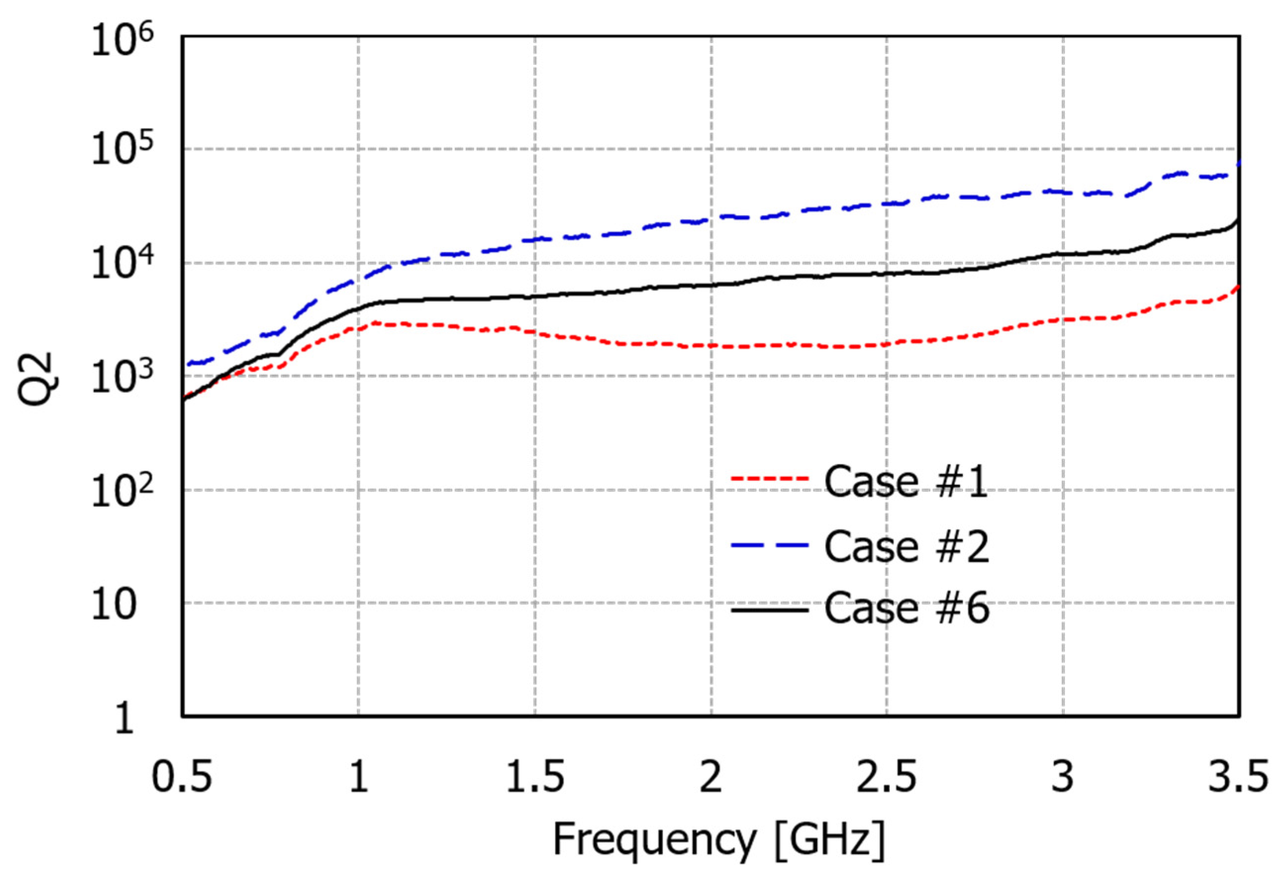
Figure 6 shows the extracted Q 2 of absorbers at three positions (cases #1, #2, and #6 in Table 1). As shown in 
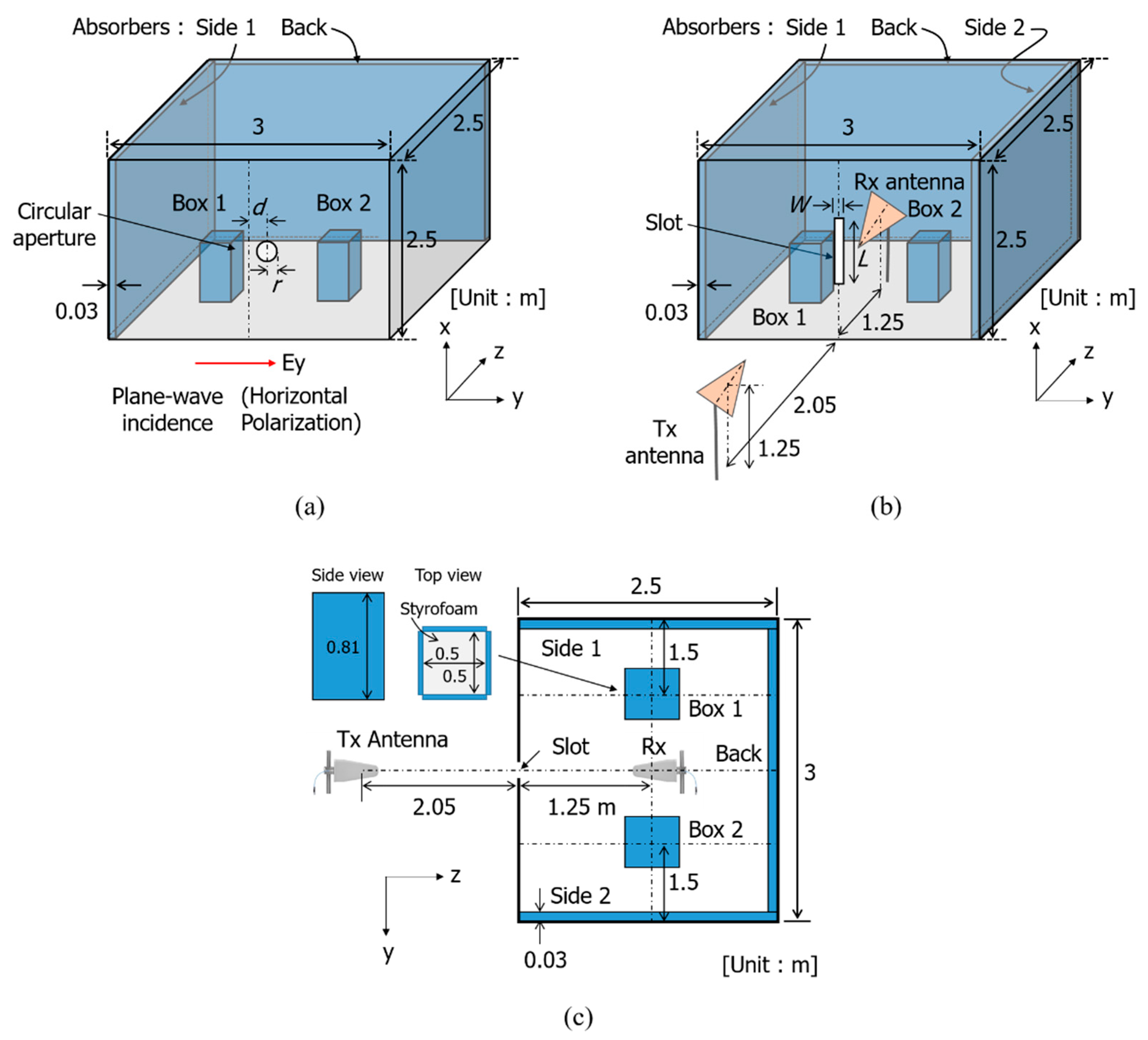
Figure 4a, when the horizontally polarized plane-wave is incident, the SEs of the shielded room with and without each absorber were calculated at the frequency range from 500 MHz to 3.5 GHz by the numerical simulation. Moreover, the simulated SEs were provided to Equation (6) and Q 2 was calculated according to the three positions of the absorbers. In this case, a circular aperture of r = 8 cm was used to analytically calculate Q 3 of the aperture loss. The simulated results in Figure 6 show that absorbers with different positions and shapes have different Q 2 , resulting in different impacts on SE improvement. The lowest Q 2 was seen when the absorber was on the back wall (case #1), while the highest Q 2 was shown for the side absorber (case #2). The Q 2 of two cuboid absorbers on the floor (case #6) had an intermediate value of the other two cases. The smaller Q 2 indicates higher absorption and SE improvement.
To examine quantitatively how much the absorbers in the shielded room improves its S E , S E U without absorber, S E L with absorber, and S E L in Equation (9) were calculated by simulation. 
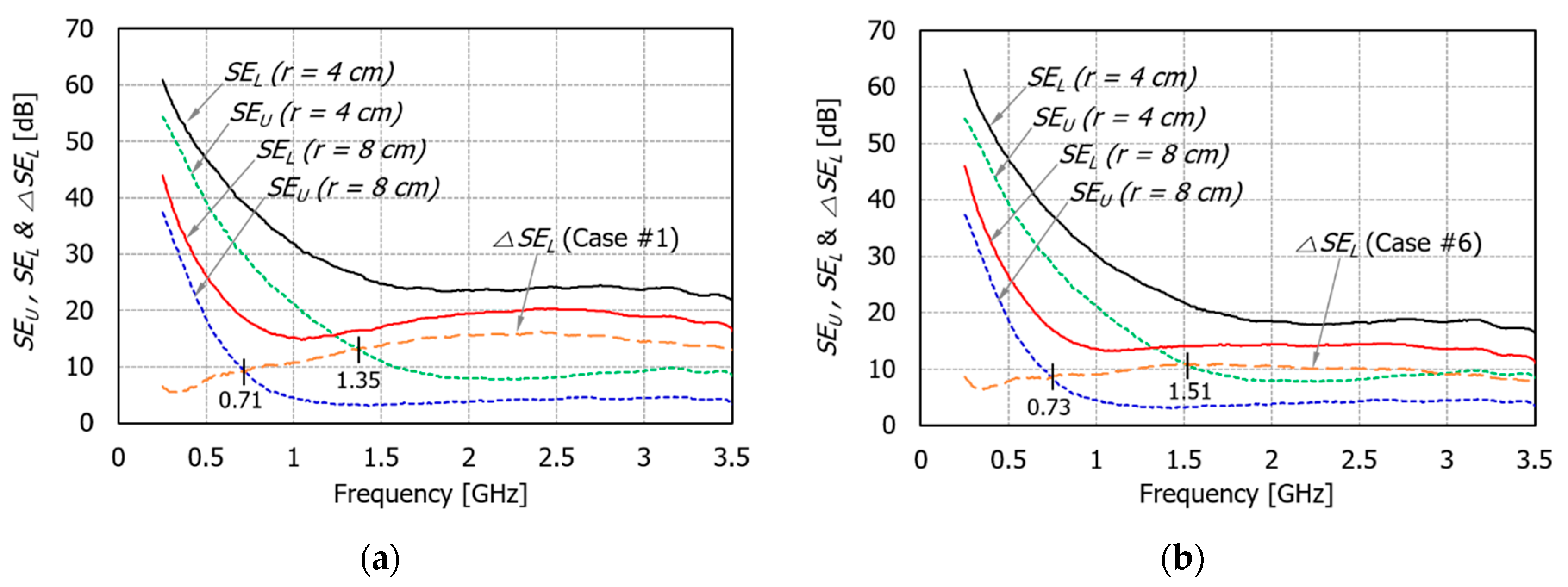
Figure 7 shows the SEs with and without absorbers ( S E L and S E U ) in the shielded room with each circular aperture of 4 cm and 8 cm in radius. For the absorbers in two cases (cases #1 and #6), the S E L in Equation (9) was also plotted. Similar to the shielding properties of typical metallic enclosures with apertures, the simulated SEs are high at a low-frequency and gradually decreases as the frequency increases. At a high-frequency above 2 GHz, the decrease of SE is not noticeable. In addition, if there is an absorber in the shielded room, the SE increases by S E L .
In Figure 7a, the SE improvement is examined when the absorber is on the back wall (case #1). When there is no absorber in the shielded room with a circular aperture of an 8 cm radius, the SE is about 5 dB at frequencies above 1 GHz. However, when loading the absorber, the SE increases to 15~20 dB at the same frequency range. When comparing S E L and S E U , S E L starts to become larger than S E U from a frequency of 0.71 GHz. It can be said that the influence of the absorber on the SE starts to become dominant from 0.71 GHz. If the radius of the circular aperture is reduced from 8 cm to 4 cm, the SE of the shielded room without absorber increases by about 3 to 5 dB above 1.5 GHz. Of course, it increased by 15~20 dB at lower frequencies. This means that the size of the aperture has a greater influence on the SE at lower frequencies. When there is an absorber, it can be seen that the SE is about 25 dB at a frequency of 1.5 GHz or higher. When comparing S E L and S E U , S E L starts to become larger than S E U from 1.35 GHz. Therefore, even if the same absorber is used, the frequency at which the influence of the absorber begins to occur dominantly on the SE varies depending on the SE level determined by the aperture on the shielded room. In other words, as the SE of the shielded room by the aperture is lowered, the SE improvement by the absorber starts to appear from the lower frequency.
In Figure 7b, the SE improvement is analyzed when two cuboid absorbers are on the floor (case #6). Since Q 2 case #6 was greater than Q 2 of case #1 shown in Figure 6, it can be seen that S E L case #6 has a lower value than that of case #1. As a result, the frequency at which S E L is greater than S E U is 0.73 GHz for a circular aperture with r = 8 cm, and 1.51 GHz for a circular aperture with r = 4 cm. These frequencies are more increased than those of case #1. In addition, improvement is also reduced when compared to case #1. Therefore, the lower the loss of the absorber, the higher the frequency at which the absorber starts to dominantly affect the SE improvement. Consequently, it can be seen that the contribution of the absorber in the shielded room to the SE improvement depends on the SE of the shielded room by the aperture as well as the position of the absorber. In addition, the SE improvement by the absorber is greater at high frequencies than low frequencies, where the influence of the aperture on the SE is dominant.
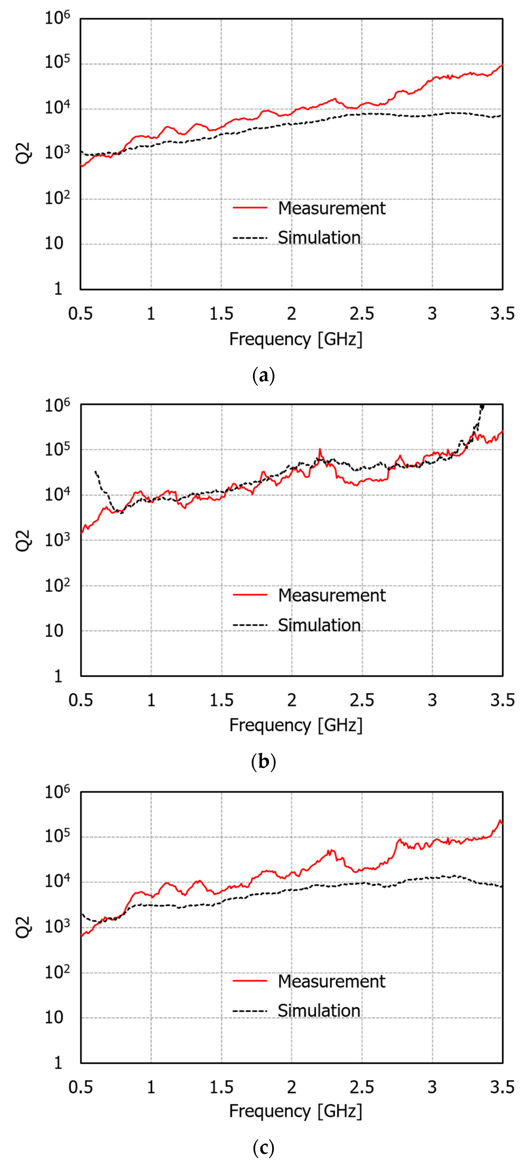
In order to verify the simulated results in Figure 6, we compared the simulated Q 2 with the measured one in Figure 8. Strictly speaking, the measured Q 2 indicates the Q 2 
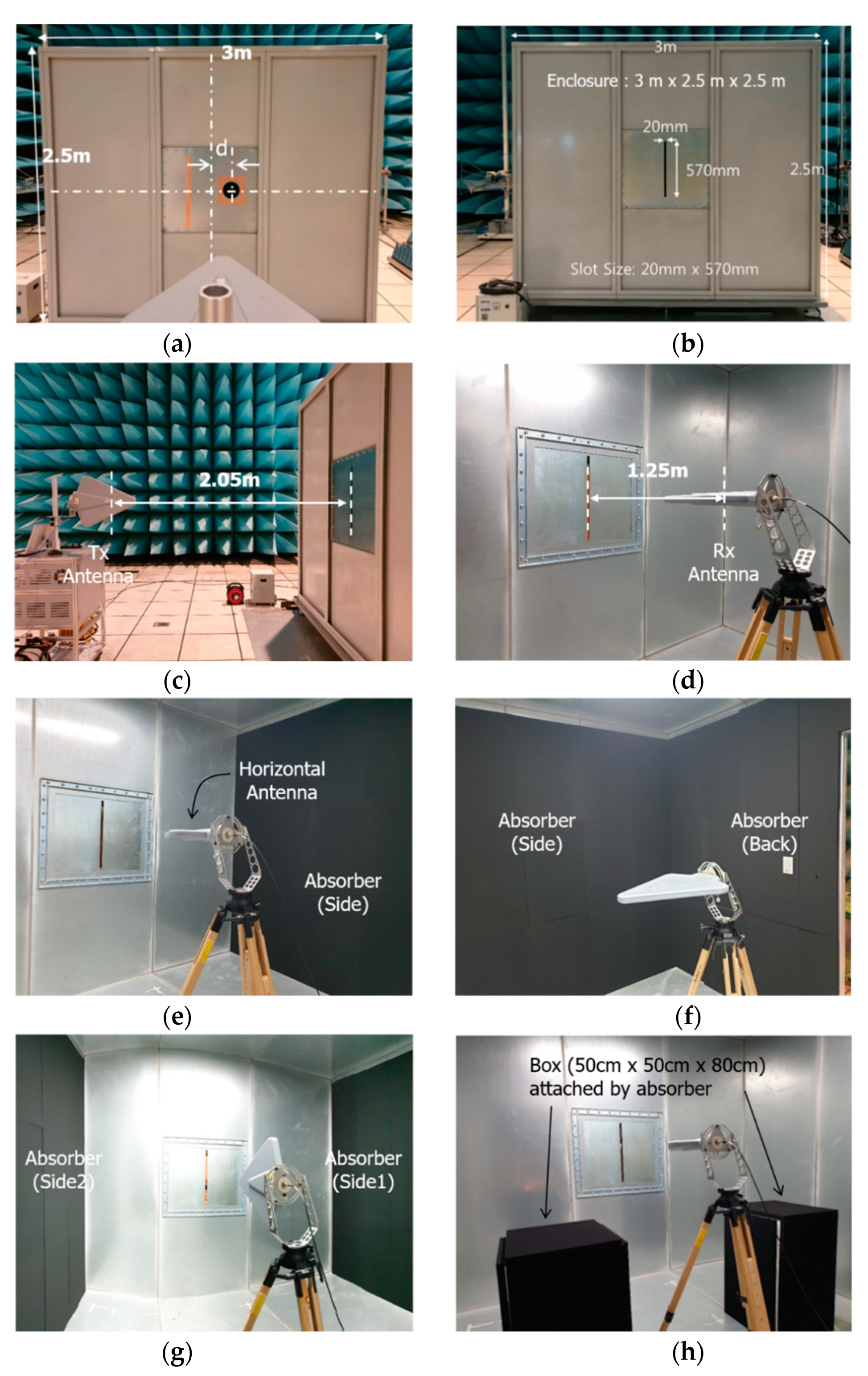
obtained through the measured SEs of the shielded room using the antenna excitation with horizontal polarization. The measurement setup is already shown in Figure 5a. In addition, the simulated Q 2 was also obtained through the simulated SEs using the antenna excitation. As can be seen in Figure 8, if the absorber was placed on the back or floor (cases #1 and #6), the measured Q 2 was larger than the simulated one and the difference between them gradually increased as the frequency increased. In particular, the difference between simulated and measured results seemed to be a little larger because the structure of absorbers in case #6 was not exactly the same in simulation and measurement. However, it can be seen that the measured and simulated Q 2 agree well with the absorber lying on the side wall.

4.2. Effect of Absorbers on the SE in Terms of Mode Density

As a second analysis, the effect of the absorber on the SE was investigated in terms of the nonresonant, under-moded, and over-moded states in the shielded room. For this, we analyzed the SE for the shielded room with a long slot by the numerical simulation and measurement, as shown in Figure 4b and Figure 5b, respectively.
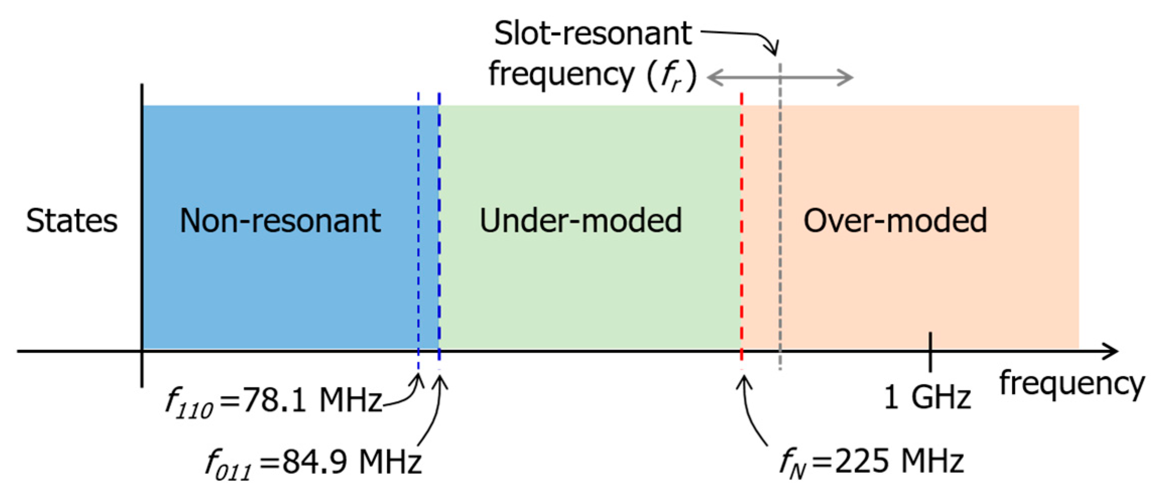
Before discussing the analysis results, the frequency of the first resonant mode and the over-moded frequency of the metallic shielded room used in this study are first calculated. Here, the over-moded frequency is defined as the frequency at which the number of resonant modes becomes more than 60 inside the shielded room [23]. The first resonant frequency of the rectangular enclosure usually occurs at (110) mode. In the case of the shielded room used here, f 110 = 78.1 MHz. However, the first resonant mode in which the incident electric field is parallel to the long direction of the enclosure actually occurs at the (011) mode, and its frequency is f 011 = 84.9 MHz. The over-moded frequency is calculated by using the formula shown in [23] and f N = 225 MHz. Therefore, as shown in Figure 9, three mode states can be defined based on these two frequencies. In the frequency range lower than 84.9 MHz, the shielded room is in a non-resonant state. The shielded room is in an over-moded state at the frequency range above 225 MHz. In the frequency range from 84.9 MHz to 225 MHz, the shielded room can be defined as an under-moded state. Therefore, we can analyze the change of SE according to the absorber in three frequency ranges corresponding to each mode state.
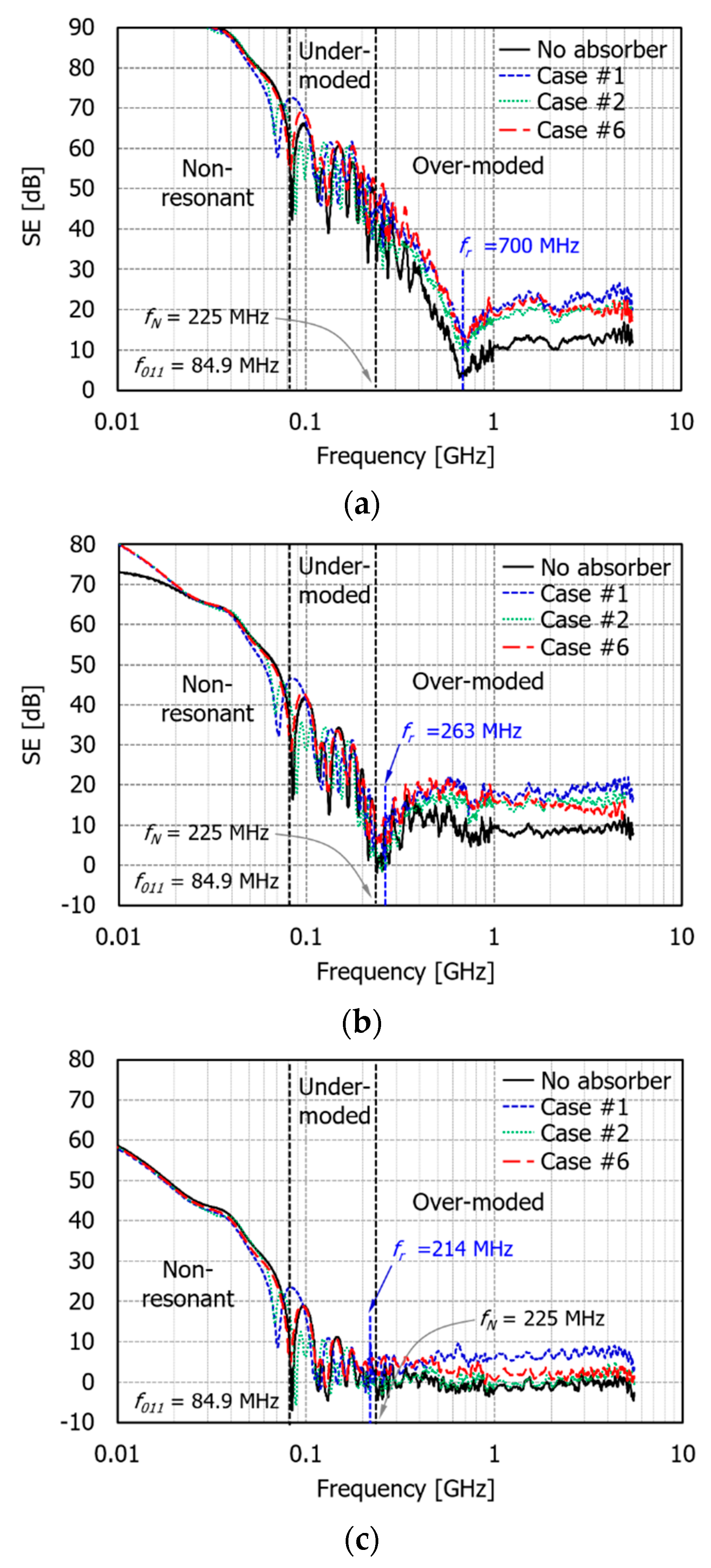
Figure 10 shows the simulation results of SE at the frequency range from 10 MHz to 6 GHz in the presence or absence of absorbers in the shielded room with three different slots. The sizes (L × W) of three different slots are 0.2 m × 0.02 m (slot #1), 0.57 m × 0.02 m (slot #2), and 0.7 m × 0.7 m (slot #3). The resonant frequency of each slot is simply calculated by f r = c / 2 L , where c is the speed of light in free space. The absorbers are also the same as the structure examined earlier (cases #1, #2, and #6). A plane-wave with horizontal polarization is incident, and then the SE is calculated by spatially averaging the electric field values at 72 positions in the shielded room. Note that the resonance occurs very densely in the over-moded frequency range, and an SE with very severe fluctuation is obtained even if the spatially averaging is performed. This makes it difficult to accurately distinguish the SE improvement depending on the absorber. To resolve this matter in the over-moded frequency range, the moving average in the frequency domain was applied to the spatially averaged electric field to get a smoother SE curve.
When the slot size is 0.2 m × 0.02 m (slot #1), the slot resonance occurs at around 700 MHz, as shown in Figure 10a. In this case, the slot resonant frequency is placed in the over-moded frequency range. When the slot size is 0.57 m × 0.02 m (slot #2), the resonant frequency of the slot is 263 MHz, as shown in Figure 10b, which lies around the over-moded frequency (225 MHz). When the slot size is 0.7 m × 0.7 m (slot #3), the resonant frequency of the slot is 214 MHz, as shown in Figure 10c, which lies in the under-moded frequency range.
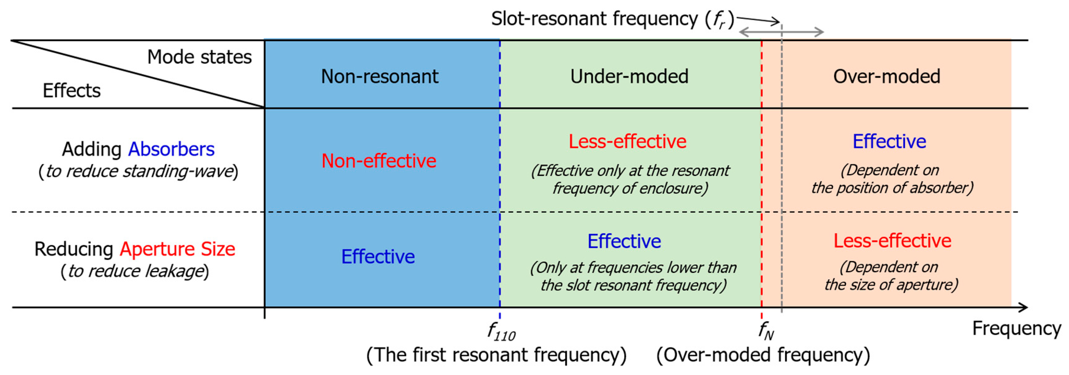
Looking at the change of SE according to the frequency in Figure 10, the SE generally decreases as the frequency increases up to the slot resonant frequency. However, at frequencies higher than the slot resonant frequency, the SE does not decrease significantly and has an almost constant level. This phenomenon is the same, even if the slot size is different. In the non-resonant frequency range, it can be seen that the SE is not changed by the presence of an absorber. This means that in the low-frequency range at the nonresonant state of the shielded room, the SE is not improved by the absorber in the shielded room. In the under-moded frequency range, the resonance mode starts to occur one-by-one, and the resonant frequency also changes according to the position of the absorber. Therefore, we can say the SE improvement by the absorber at a specific resonant frequency, but it is difficult to say that the overall level of SE was increased by the absorber. Further simulation and measurement in the under-moded frequency range are shown later, and a more detailed discussion is provided.
Lastly, let us look at the characteristic of the SE improvement by the absorber in the over-moded frequency range. In the case of slot #1 shown in Figure 10a, since the slot resonant frequency is within the over-moded frequency range, we will consider the effect of the absorber by dividing the frequency range into higher and lower frequencies than the slot resonant frequency. First, in the frequency range higher than the slot resonant frequency ( f > 700 MHz), the SE improvement by the absorber is clearly seen. When the absorber is on the back wall (case #1), the SE is improved by about 10 dB in the frequency range of 1 to 6 GHz. When the absorber is on the side wall (case #2), it is improved by around 6 to 8 dB at the same frequency range. In the case of two cuboid absorbers on the floor (case #6), the SE improvement is similar to case #1 at 1~2 GHz and case #2 at 2~6 GHz. Therefore, it can be seen that different improvement characteristics of SE are shown depending on the position of the absorber. These results are also consistent with the Q 2 results of the three absorbers shown in Figure 6. At the frequencies lower than the slot resonant frequency (225 MHz < f < 700 MHz), it can be seen that the SE of the shielded room with the absorber has a higher value within 10 dB than that without the absorber. In addition, cases #1 and #6 have slightly higher SE values than case #2. Therefore, we can conclude that the SE improvement can be achieved by the absorber when the shielded room is in an over-moded state even at frequencies lower than the slot resonant frequency.
When the slot size is 0.57 m × 0.02 m (slot #2), as shown in Figure 10b, it is meaningless to divide the over-moded frequency region based on the slot resonant frequency because the slot resonant frequency (263 MHz) and over-moded frequency (225 MHz) are similar. It can be seen that the SE of the shielded room with the absorber is improved by 6~10 dB in the over-moded frequency range. However, it is difficult to say that the overall SE is improved by the absorber in the under-moded range lower than the slot resonant frequency. When the slot size is 0.7 m × 0.7 m (slot #3) as shown in Figure 10c, in the over-moded frequency range, when the absorber is in the back wall (case #1), the SE is improved by 5~8 dB in the frequency range above 500 MHz. In cases #2 and #6 of absorbers, the SE improvement was not significant. This is because if the size of the slot is too large, the intensity of the reverberating field in the shielded room is weakened, and then the field attenuation by the absorber is not great. Therefore, it can be seen that the degree of SE improvement by the absorber in the over-moded frequency range alters accordingly to the slot size of the shielded room.
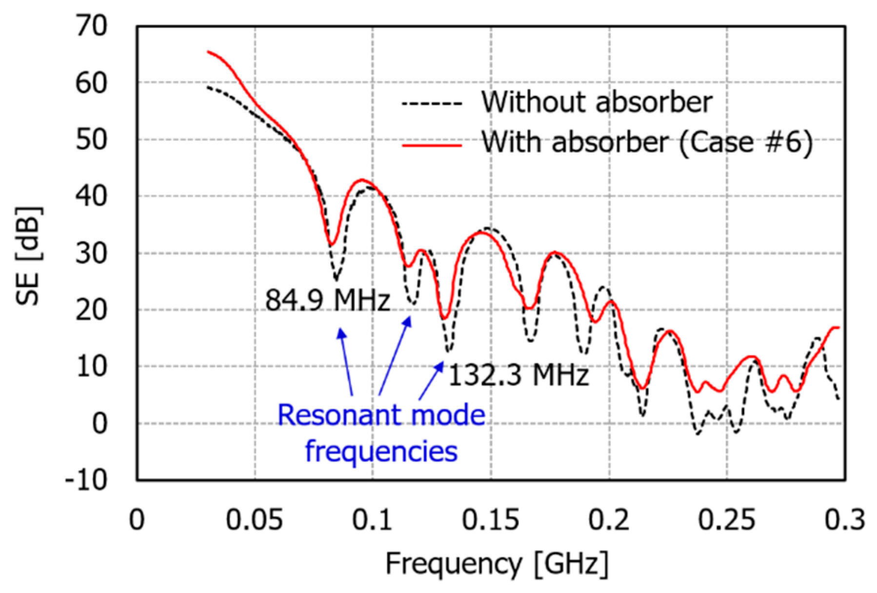
In order to examine the SE improvement characteristics by the absorber at the under-moded frequency range in detail, the results of Figure 10b were redrawn in Figure 11 by expanding the frequency up to 300 MHz only. The SE results are compared with two cases: the presence and absence of two cuboid absorbers on the floor (case #6) in the shielded room with slot #2 (0.57 m × 0.02 m). Here, we can see that the SE of the shielded room is greatly reduced at the resonant mode frequencies. However, if there is the absorber of case #6, the amount of reduction decreases and then the SE is improved. In addition, it can be seen that SE is hardly improved by the absorber at frequencies other than the resonant mode frequencies. As a result, it can be said that in the under-moded frequency range, the SE is improved by the absorber only at the resonant frequencies of the shielded room, but the overall SE level is not improved.
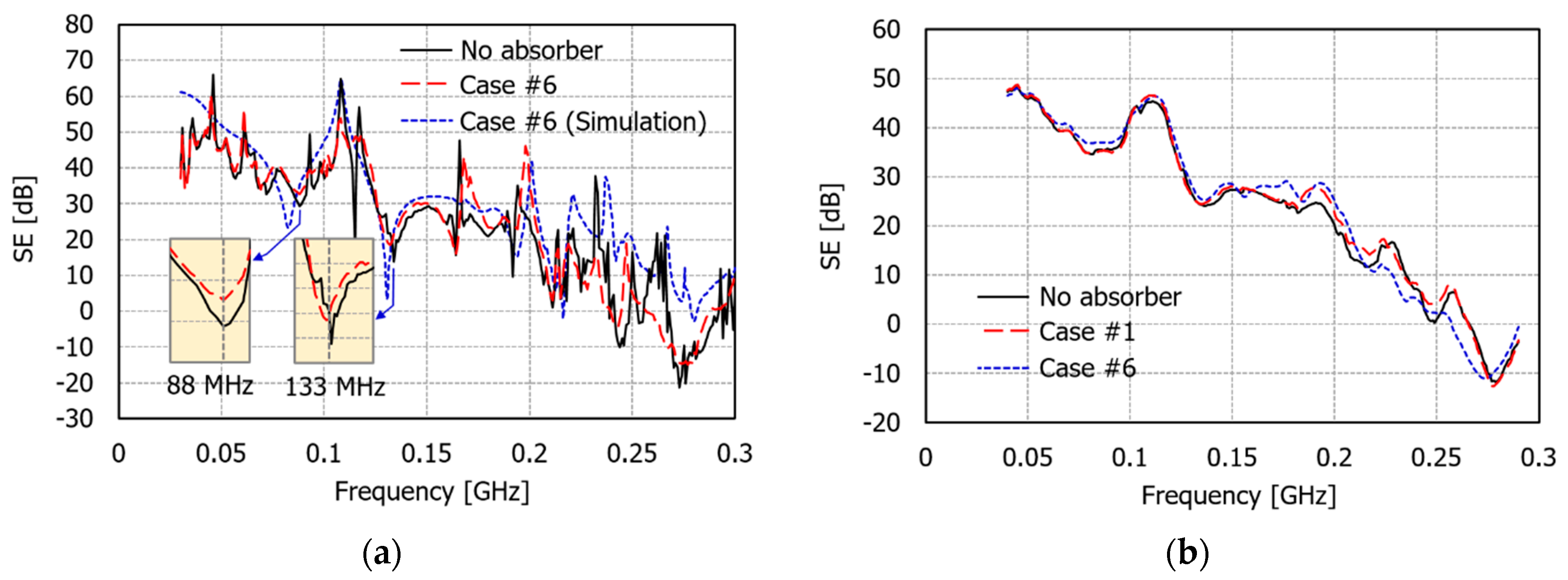
In order to verify these results through an experiment, the SE was measured in the frequency range of 30~300 MHz using the structure in Figure 4b and biconical antennas with horizontal polarization. Figure 12 compares the measured SEs for the cases with and without two cuboid absorbers on the floor (case #6). For verification, the SE calculated using the simulated electric field at the center of the shielded room in the presence of the absorber was also plotted. First of all, Figure 12a shows that the simulated result agrees relatively well with the measured SE. It can also be seen that the SE increases slightly at two resonant frequencies (88 MHz and 133 MHz) when there is the absorber (case #6). To check whether the SE is improved overall by the absorber in the under-moded frequency range, Figure 12b shows the results of applying the moving average to the measured SEs in Figure 12a. The measured SE of the absorber on the back wall (case #1) was also plotted. When comparing the measured SE without the absorber, it is difficult to say that the SE is improved by the absorber.
Next, the variation of the SE improvement by different absorbers in the over-moded frequency range was examined through measurement. The SE was measured in the frequency range of 400 MHz~6 GHz using the structure in Figure 4b and log periodic antenna with both horizontal and vertical polarizations. The slot size of the shielded room is 0.57 m × 0.02 m (slot #2). The measurements were performed in all cases listed in Table 1. As mentioned earlier, to show the degree of the SE improvement more clearly by each case in the over-moded frequency range, the SE was calculated by applying the central moving average to the original measured results with a very reverberant behavior.
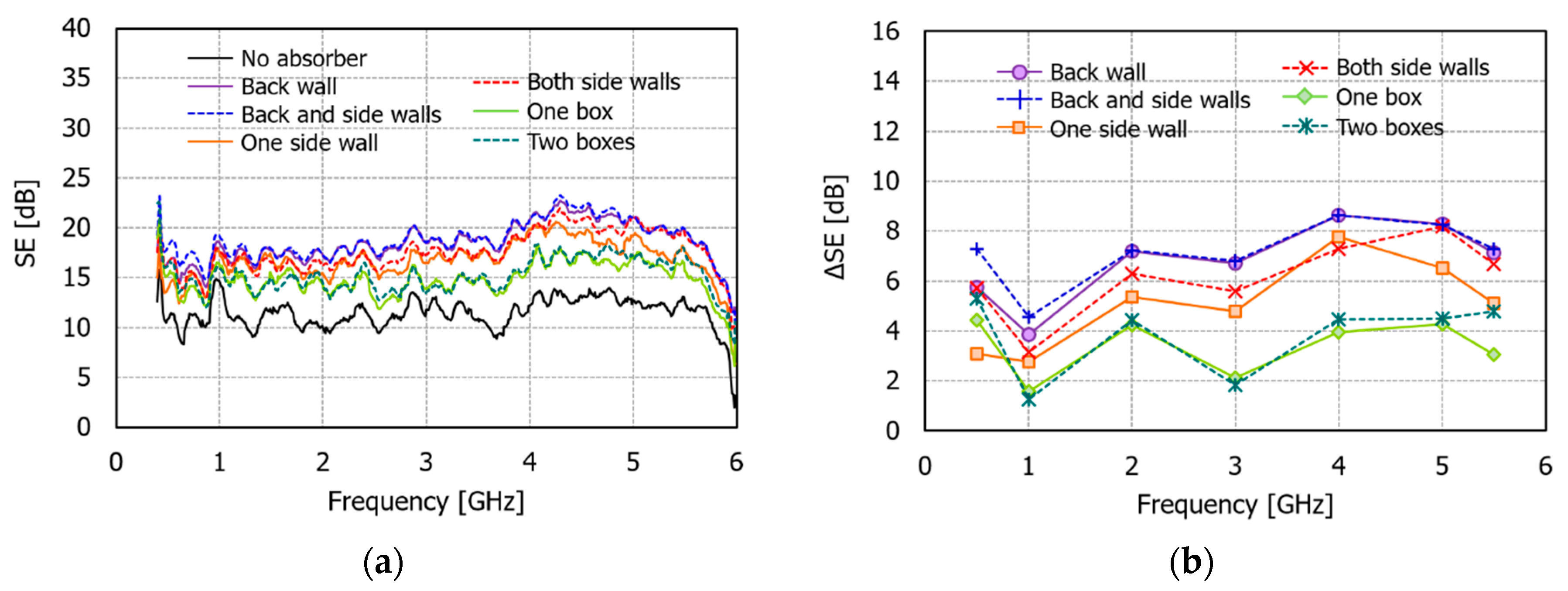
Figure 13 shows the measured SE results of the shielded room in the presence of the horizontally polarized incident field. In Figure 13b, the SE improvement values for the cases with absorbers compared to the SE of the room without absorbers are plotted as the frequency varies. First, the SE of the room without an absorber is 10~13 dB in Figure 13a. For the cases of the room with absorbers, case #1 (back wall) and case #3 (back and side walls) had the highest SE with a maximum improvement of 8.6 dB at 4 GHz compared to the SE of the room in the absence of absorbers. Comparing these two cases in Figure 13b, it can be seen that case #3 has a higher SE than case #1 in the frequency range below 2 GHz while having almost the same SE at frequencies above 2 GHz. As a result, applying the absorbers only to the back wall can achieve a sufficient improvement in the SE. However, if it is needed to be improved further at a lower frequency, an additional absorber should be attached to the side wall together with the back wall.
In cases where the absorbers were attached only to the side walls (cases #2 and #4), the SE was slightly lower than those attached to the back wall. When the absorber was on both sides, the SE was about 1~2 dB higher than that of the absorber on only one side, but the difference was not large. Therefore, attaching the absorbers only on one side could sufficiently reduce the standing-wave effect. In the case of the absorber in the box form (cases #5 and #6), the SE could be improved up to 4 dB compared with the case without the absorber. However, the improvement was less than the cases that the absorbers were attached to the back or side walls.
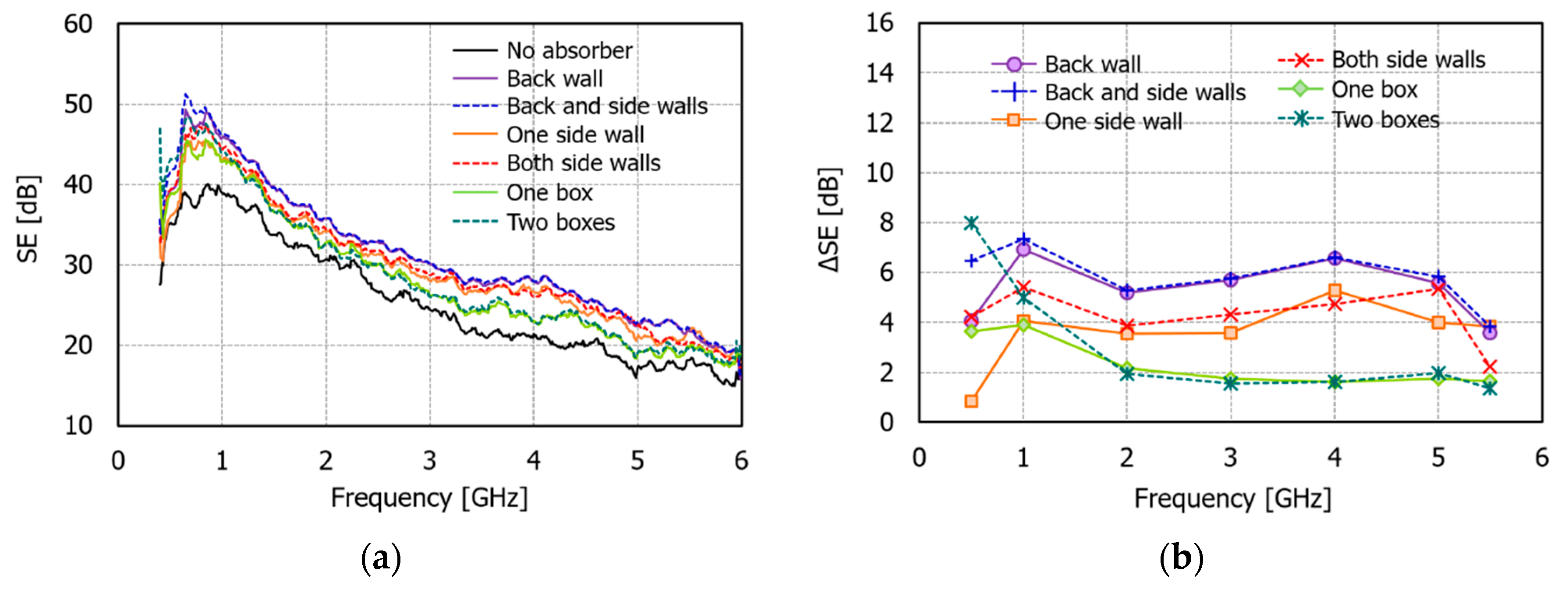
Figure 14 shows the measured SE results of the shielded room in the presence of the vertically polarized incident field. Compared with Figure 13, the SE was higher in the case of vertical polarization. This was because the electric field penetrating through the slot was reduced if the electric field direction was the same as the axis of the long side of the slot. The degree of the SE improvement by the absorbers was slightly reduced compared to that of the horizontal polarization. However, there clearly was an SE improvement by the absorbers: cases #1 and #3 were about 6 dB, cases #2 and #4 were about 4 dB, and cases #5 and #6 were around 2 dB, as shown in Figure 14b. The change of the shielding improvement effect according to the position of the absorbers was the same as the horizontal polarization.
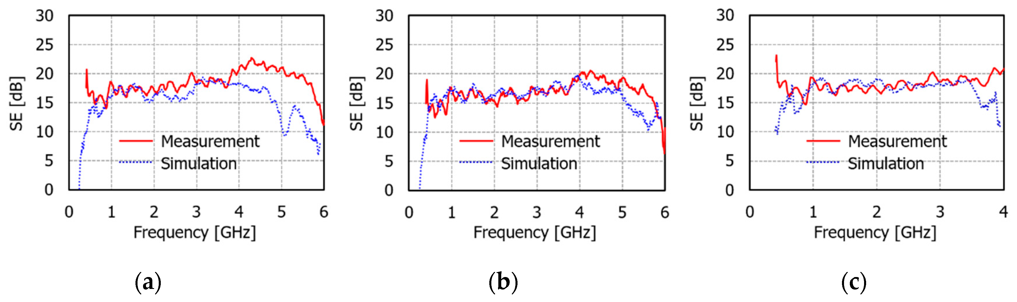
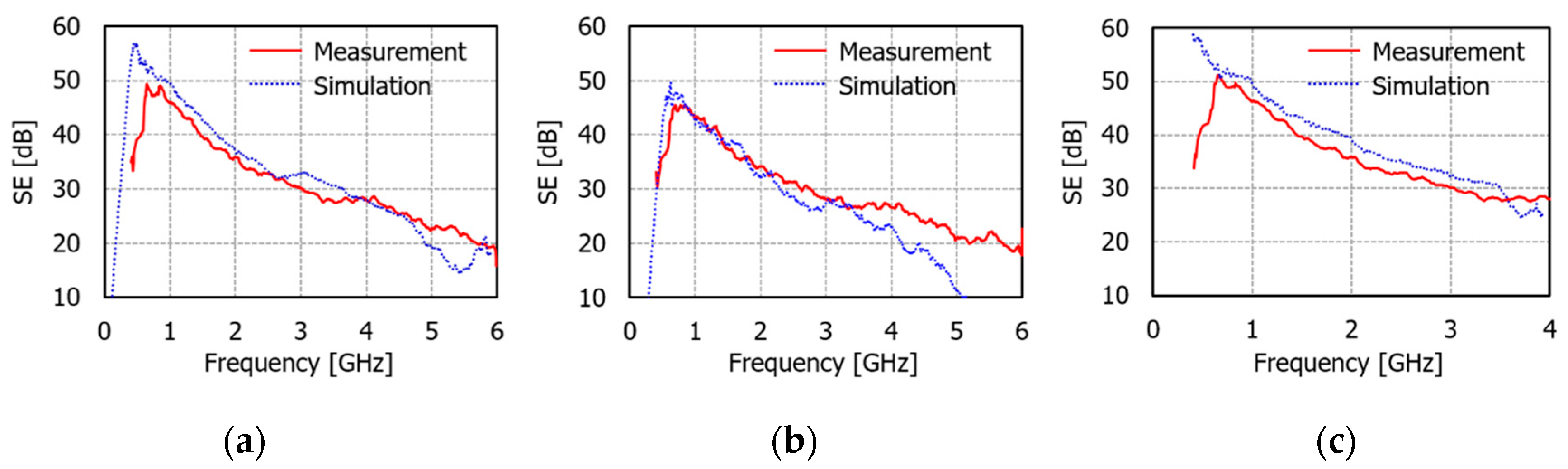
Figure 15 and Figure 16 show the comparison of measured and simulated SE results using the antenna excitation for the three cases of #1, #2, and #3. Although the simulation model was not exactly the same absorber as that used in the measurement [26], it can be seen that the SEs of the measurement and the simulation correspond well at the frequency range up to around 3.5 GHz in both horizontal and vertical polarizations. The simulation results also showed slightly higher SEs in both polarizations if the absorber was on the back wall than if it was on the side wall. In particular, the difference occurring at the frequency range above 4 GHz seemed to be caused by the inaccuracy of the high-frequency model of the absorber used in the simulation. However, it can be seen that the measurement and simulation results presented in Figure 15 and Figure 16 were generally similar, although there are differences depending on the frequency. These results confirm the accuracy of the simulation and measurement results.

4.3. Summary of the Effects of Absorbers on the SE

As mentioned in the introduction, the shielding characteristics of a shielded room are determined by three effects. One of them is the leakage effect due to the unknown aperture, and another is the standing-wave effect of electromagnetic waves penetrating into the shielded room. So far, we have investigated how the absorber existing in a large, shielded room with an aperture or slot affects the SE improvement through numerical simulation and experimental measurement. Using an absorber in the shielded room could improve the SE reduction due to the standing-wave of electromagnetic waves penetrated into the aperture. However, the effect changed according to the aperture size, the position of the absorber, and the mode density in the shielded room. Based on the analysis results, the effects of the absorber and aperture in the three frequency ranges divided by the mode density in the shielded room are summarized in Figure 17.
In the non-resonant frequency range, there is no SE improvement by the absorber because the standing-wave by resonance in the shielded room does not occur. In this frequency range, the size of the aperture or slot greatly affects the shielding performance of the shielded room. Therefore, in order to improve the SE, an unknown aperture or slot must be found and removed. In addition, at low frequencies below the kHz band, the diffusion effect of the magnetic field penetrating through the conducting wall cannot be ignored, so the selection of the material and its thickness of the shielded room walls becomes important [7].
In the under-moded frequency range where the number of resonant modes is not large (typically less than 60 modes), it can be said that the SE improvement obtained by reducing the aperture size is greater than the SE improvement obtained by placing the absorber. If the resonant frequency of the slot is within the under-moded frequency range, reducing the aperture size is only effective at frequencies lower than the slot resonant frequency. This can be seen by comparing the SE results according to the three different sizes of the slot in Figure 10. Furthermore, in the under-moded frequency range, the absorber is effective only at the resonant mode frequencies of the shielded room but does not increase the overall SE level.
In the over-moded frequency range, the standing-wave caused by the reverberating field is severely generated due to the numerous resonant modes, resulting in a SE reduction in the shielded room. Using the absorber in this environment increases the overall SE level effectively by reducing the standing-wave. In addition, based on the simulation and measurement results [27], the location of the absorber influences the amount of SE improvement.

5. Conclusions

This paper has explored the effect of an absorbent material (absorber) to improve the SE of large metallic rooms with apertures or slots. First, the theoretical formulation to extract the Q-factor of an absorber with any shape was proposed. Using this, the contribution of the absorber to the SE improvement of a shielded room with different sized circular apertures was examined. Second, the mode density in the shielded room was classified into nonresonant, under-moded, and over-moded states with an increase in frequency, and the effect of the absorber in each frequency range was investigated. The analyses were conducted through a numerical simulation using a commercial full-wave simulator and experimental measurement using a fabricated actual shielded room and commercial absorber. The accuracy of the analysis results was verified through the comparison of simulated and measured results. The analysis results show that the absorber is not effective in improving the SE in the nonresonant frequency range. It is also confirmed that the absorber is effective in improving the SE in the over-moded frequency range where standing-wave occurs severely, and the SE improvement level differs depending on the location of the absorber in the shielded room. Consequently, the absorbers could be used to cost-effectively improve the shielding performance of large, shielded rooms or facilities with unknown apertures or slots at the over-moded frequency range. However, there was little effect of shielding improvement in the under-moded frequency range. Therefore, as an extended work, it is necessary to study the placement method of the absorbers that is effective for under-moded resonant frequencies.

Author Contributions

Conceptualization, J.H.K. and H.H.P.; methodology, J.H.K. and H.H.P.; software, H.H.P.; validation, C.H.H., J.-H.H. and J.H.K.; formal analysis, H.H.P.; investigation, H.H.P.; data curation, C.H.H., J.H.K. and H.H.P.; writing—original draft preparation, J.H.K. and H.H.P.; writing—review and editing, J.H.K. and H.H.P.; project administration, J.-H.H. and J.H.K.; funding acquisition, J.H.K. All authors have read and agreed to the published version of the manuscript.

Funding

This research was supported by the Institute of Information and Communications Technology Planning and Evaluation (IITP) grant funded by the Korean government (MSIT) (No. 2020-0-00917, Development of Key Technologies for Low-cost EMP Protective Materials, Components, Devices (MCD) and Facilities Vulnerability Assessment).

Conflicts of Interest

The authors declare no conflict of interest.

References

  1. Li, M.; Ma, K.-P.; Drewniak, J.L.; Hubing, T.H.; Van Doren, T.P. Numerical and experimental corroboration of an FDTD thin-slot model for slots near corners of shielding enclosures. IEEE Trans. Electromagn. Compat. 1997, 39, 225–232. [Google Scholar]
  2. Cerri, G.; de Leo, R.; Primiani, V.M.; Righetti, M. Field penetration into metallic enclosures through slots excited by ESD. IEEE Trans. Electromagn. Compat. 1994, 36, 110–116. [Google Scholar] [CrossRef]
  3. Xia, N.; Yi, X.; Song, W. Shielding effectiveness and coupling characteristic of metallic enclosures with apertures under EMP. In Proceedings of the 2009 Asia-Pacific Power and Energy Engineering Conference, Wuhan, China, 27–31 March 2009; pp. 1–4. [Google Scholar]
  4. Frikha, A.; Bensetti, M.; Duval, F.; Benjelloun, N.; Lafon, F.; Pichon, L. A new methodology to predict the magnetic shielding effectiveness of enclosures at low frequency in the near field. IEEE Trans. Magn. 2015, 51, 8000404. [Google Scholar] [CrossRef]
  5. Whitehous, A.C.D. Screening: New wave impedance for the transmission line analogy. Proc. IEEE 1969, 116, 1159–1164. [Google Scholar] [CrossRef]
  6. Moser, J.R. Low-frequency low-impedance electromagnetic shielding. IEEE Trans. Electromagn. Compat. 1988, 30, 202–210. [Google Scholar] [CrossRef]
  7. Park, H.H.; Kwon, J.H. Low-frequency magnetic shielding analysis of a metal plate without and with a slot. In Proceedings of the 2019 International Symposium on Electromagnetic Compatibility-EMC EUROPE, Barcelona, Spain, 2–6 September 2019; pp. 539–543. [Google Scholar]
  8. Ott, H.W. Electromagnetic Compatibility Engineering, 1st ed.; John Wiley & Sons, Inc: Hoboken, NJ, USA, 2009. [Google Scholar]
  9. MIL-STD-188/125-1, Department of Defense Interface Standard: High-Altitude Electromagnetic Pulse(HEMP) Protection for Ground-Based C4I Facilities Performing Critical, Time-urgent Missions (Part 1—Fixed Facilities). Available online: https://www.volta.it/wp-content/uploads/2017/09/MIL-STD-188-125-2.pdf (accessed on 17 July 2019).
  10. IEEE STD 299. IEEE Standard Method for Measuring the Effectiveness of Electromagnetic Shielding Enclosure; IEEE: New York, NY, USA, 1997. [Google Scholar]
  11. Park, H.H.; Eom, H.J. Electromagnetic penetration into a rectangular cavity with multiple rectangular apertures in a thick conducting plane. IEEE Trans. Electromagn. Compat. 2000, 42, 303–307. [Google Scholar] [CrossRef]
  12. Olyslager, F.; Laermans, E.; De Zutter, D.; Criel, S.; De Smedt, R.; Lietaert, N.; De Clercq, A. Numerical and experimental study of the shielding effectiveness of a metallic enclosure. IEEE Trans. Electromagn. Compat. 1999, 41, 202–213. [Google Scholar] [CrossRef]
  13. Bait-Suwailam, M.M.; Alavikia, B.; Ramahi, O.M. Reduction of electromagnetic radiation from apertures and enclosures using electromagnetic bandgap structures. IEEE Trans. Compon. Packag. Manuf. Technol. 2014, 4, 929–937. [Google Scholar] [CrossRef]
  14. Siah, E.S.; Sertel, K.; Volakis, J.L.; Liepa, V.V.; Wiese, R. Coupling studies and shielding techniques for electromagnetic penetration through apertures on complex cavities and vehicular platforms. IEEE Trans. Electromagn. Compat. 2003, 45, 245–257. [Google Scholar] [CrossRef] [Green Version]
  15. Park, H.H.; Hyoung, C.H.; Kwon, J.H. Improvement of low-frequency magnetic shielding measurement using rhombic and long rectangular loop antennas. IEEE Trans. Electromagn. Compat. 2020, 62, 1364–1368. [Google Scholar] [CrossRef]
  16. Parker, S.L.; Flintoft, I.D.; Marvin, A.C.; Dawson, J.F.; Bale, S.J.; Robinson, M.P.; Ye, M.; Wan, C.; Zhang, M. Predicting shielding effectiveness of populated enclosures using absorption cross section of PCBs. In Proceedings of the 2016 International Symposium on Electromagnetic Compatibility-EMC EUROPE, Wroclaw, Poland, 5–9 September 2016; pp. 324–328. [Google Scholar]
  17. Flintoft, I.D.; Parker, S.L.; Bale, S.J.; Marvin, A.C.; Dawson, J.F.; Robinson, M.P. Measured average absorption cross-sections of printed circuit boards from 2 to 20 GHz. IEEE Trans. Electromagn. Compat. 2016, 58, 553–560. [Google Scholar] [CrossRef]
  18. Washbourne, L.J.; Rajamani, V.; Bunting, C.F.; West, J.C.; Archambeault, B.; Connor, S.; Rajamani, V. Effectiveness of absorbing materials on reducing electromagnetic emissions from cavities measured using a nested reverberation chamber approach. In Proceedings of the 2014 IEEE International Symposium on Electromagnetic Compatibility (EMC), Raleigh, NC, USA, 4–8 August 2014; pp. 909–912. [Google Scholar]
  19. Kwon, J.H.; Hwang, J.H.; Park, H.H. Improving shielding effectiveness of enclosure with apertures using absorbers. In Proceedings of the 2019 IEEE International Symposium on Electromagnetic Compatibility, Signal & Power Integrity (EMC+SIPI), New Orleans, LA, USA, 22–26 July 2019; pp. 356–359. [Google Scholar]
  20. Dawson, L.; Dawson, J.F.; Marvin, A.C.; Welsh, D. Damping resonances within a screened enclosure. IEEE Trans. Electromagn. Compat. 2001, 43, 45–55. [Google Scholar] [CrossRef]
  21. Dawson, L.; Clegg, J.; Porter, S.J.; Dawson, J.F.; Alexander, M.J. The use of genetic algorithms to maximize the performance of a partially lined screened room. IEEE Trans. Electromagn. Compat. 2002, 44, 233–242. [Google Scholar] [CrossRef]
  22. Hill, D.A.; Ma, M.T.; Ondrejka, A.R.; Riddle, B.F.; Crawford, M.L.; Johnk, R.T. Aperture excitation of electrically large, lossy cavities. IEEE Trans. Electromagn. Compat. 1994, 36, 169–178. [Google Scholar] [CrossRef]
  23. Hill, D.A. Electromagnetic Fields in Cavities: Deterministic and Statistical Theories, 1st ed.; John Wiley & Sons, Inc.: Hoboken, NJ, USA, 2009. [Google Scholar]
  24. E-SONG EMC Co., Ltd. Available online: https://esongemc.com/kr/ (accessed on 4 May 2020).
  25. Microwave Studio (MWS), CST. 2020. Available online: https://www.3ds.com (accessed on 14 July 2020).
  26. Study on the Influence of Electromagnetic Shielding Effectiveness in Shielding Structures; Final Research Report; ETRI: Daejeon, Korea, 2019.
  27. Study on the Influence of Electromagnetic Absorbing Materials Placed in Facilities; Final Research Report; ETRI: Daejeon, Korea, 2020.
Figure 1. Shielding effectiveness of a large metallic enclosure: (a) material effects; (b) leakage effect due to apertures or slots; (c) standing-wave effect.
Electronics 10 00237 g001
Figure 2. Three losses in a large, shielded room that determine the shielding effectiveness (SE).
Electronics 10 00237 g002
Figure 3. Calculation flow for Q 2 and SE of the enclosure with circular apertures in different sizes.
Electronics 10 00237 g003
Figure 4. Configuration of structures used in numerical and experimental analyses: (a) geometry for analyzing Q 2 of absorber; (b) geometry for examining the SE in terms of the mode density in the shielded room; (c) top view and dimension of the cuboid absorber.
Electronics 10 00237 g004
Figure 5. Pictures of SE measurement: (a) front view of the fabricated shielded room with a circular aperture; (b) front view of the fabricated shielded room with a long slot; (c) transmitting (Tx) antenna in front of the room; (d) receiving (Rx) antenna inside the room; (e) absorber attached to the side wall; (f) absorbers attached to back and side walls; (g) absorbers attached to both side walls; (h) two boxes with absorbers on the floor.
Electronics 10 00237 g005
Figure 6. Simulated Q 2 of three absorbers (cases #1, #2, and #6 in Table 1) using plane-wave incidence.
Electronics 10 00237 g006
Figure 7. Comparison of simulated S E U , S E L , and S E L : (a) absorber on back wall (case #1); (b) absorbers on the floor (case #6).
Electronics 10 00237 g007
Figure 8. Measured and simulated Q 2 of absorbers using antenna excitation with horizontal polarization: (a) absorber on the back wall (case #1); (b) absorber on the side wall (case #2); (c) absorbers on the floor (case #6).
Electronics 10 00237 g008
Figure 9. Three frequency ranges in terms of mode density inside the shielded room.
Electronics 10 00237 g009
Figure 10. Comparison of simulated SE results at the three mode states in the frequency range from 10 MHz to 6 GHz: (a) SEs of the shielded room with slot #1; (b) SEs of the shielded room with slot #2; (c) SEs of the shielded room with slot #3.
Electronics 10 00237 g010
Figure 11. Simulated SE results of the shielded room with the slot of 0.57 m × 0.02 m at the under-moded frequency range.
Electronics 10 00237 g011
Figure 12. Measured SE results of the shielded room with the slot of 0.57 m × 0.02 m at the under-moded frequency range: (a) before applying the moving average; (b) after applying the moving average.
Electronics 10 00237 g012
Figure 13. Measured SE results of the shielded room for horizontal polarization: (a) moving averaged SEs; (b) SE improvement by the absorbers.
Electronics 10 00237 g013
Figure 14. Measured SE results of the shielded room for vertical polarization: (a) moving averaged SEs; (b) SE improvement by the absorbers.
Electronics 10 00237 g014
Figure 15. Comparison of measured and simulated SEs for the shielded room with the absorber for horizontal polarization: (a) case #1; (b) case #2; (c) case #3.
Electronics 10 00237 g015
Figure 16. Comparison of measured and simulated SEs for the shielded room with the absorber for horizontal polarization: (a) case #1; (b) case #2; (c) case #3.
Electronics 10 00237 g016
Figure 17. Summarized effects of adding absorber (reducing standing-wave) and reducing aperture or slot (reducing leakage) on SE in terms of the mode states in the shielded room.
Electronics 10 00237 g017
Table 1. Cases of absorber configuration.
CasesPosition of Absorbers
ReferenceNo absorber
#1Back wall
#2Side wall
#3Back and side walls
#4Two side walls
#5One box on the floor
#6Two boxes on the floor
Publisher’s Note: MDPI stays neutral with regard to jurisdictional claims in published maps and institutional affiliations.

