1. Introduction
An antilock braking system (ABS) is an important system to ensure the safety of automobile braking. It can ensure that the wheels are not locked during the braking process, improve the directional stability of the vehicle and the steering ability, and shorten the braking distance. The regenerative braking system is also an important system for hybrid electric vehicles. The motor converts the braking energy into electrical energy. Thus, it can improve the cruising range of the vehicle. It is an important research content for the coordinated control of the regenerative braking system and ABS.
At present, scholars have conducted extensive research on the coordinated control of the regenerative braking system and ABS. The literature [
1,
2,
3,
4] mainly studies how regenerative braking systems and ABSs participate in the braking process and the distribution algorithm of electric brake and mechanical brake is also proposed to ensure the proper slip rate. The control algorithm is based on logical thresholds or fuzzy control algorithms. The authors of [
5] proposed an algorithm to estimate the brake master cylinder pressure, valve body flow and other parameters to make the system coordinated control process smoother. In another study [
6], the distribution method of regenerative braking and mechanical braking based on model predictive control and Lyapunov theory is proposed. Then the impact of pedal pulse signals under emergency braking conditions is eliminated. Other studies [
7,
8] divide the required braking force into a dynamic part and a steady part which are provided by the motor and the mechanical brake, respectively, making the system coordinated and the control process smoother.
A composite structure motor (CSM) was firstly proposed by Professor Martin Hoeijmakers [
9,
10] in the Netherlands in 2001. As a special structure motor with dual mechanical and dual electrical ports, it can implement a variety of energy conversion methods and is very convenient when applied in energy conversion of HEV. A hybrid electric vehicle based on a composite structure motor (CSM-HEV) can realize the functions of planetary gear proposed by Toyota. A method for early fault diagnosis in a motor is proposed by Adam Glowacz. He also presented rotor fault diagnostic techniques of a three-phase induction motor (TPIM). The safety of the motor is ensured [
11,
12].
Most of the current research on energy management of CSM-HEV focuses on the driving control. According to the characteristics of different operating modes of CSM-HEV, research [
13,
14,
15,
16,
17,
18] has focused on the switching control of different modes and the power distribution control of internal combustion engine (ICE) and CSM. Taking the braking force distribution ratio, system operating efficiency or ICE state as the target, logic threshold method, fuzzy control method or neural network control are proposed to realize the coordination control. The regenerative braking system is an important system in CSM-HEV. Its control idea is the same as the control mode of ordinary hybrid vehicles which is that only the external motor participates in the regenerative braking process. Thus, the advantages of CSM are not fully achieved and there are still no studies on the coordinated control of a regenerative braking system and an ABS.
This paper mainly studies the coordinated control of CSM-HEV’s regenerative braking and ABS. Firstly, two new regenerative braking modes, engine-motor coordinated braking (EMCB) and dual-motor braking (DMB), are proposed. The coordinated control model of regenerative braking system and ABS is proposed. With the goal of ensuring the optimal slip rate and the system operating efficiency as the control goals, a braking force distribution algorithm based on model predictive control is proposed.
2. Analysis of the New Braking Mode in CSM-HEV
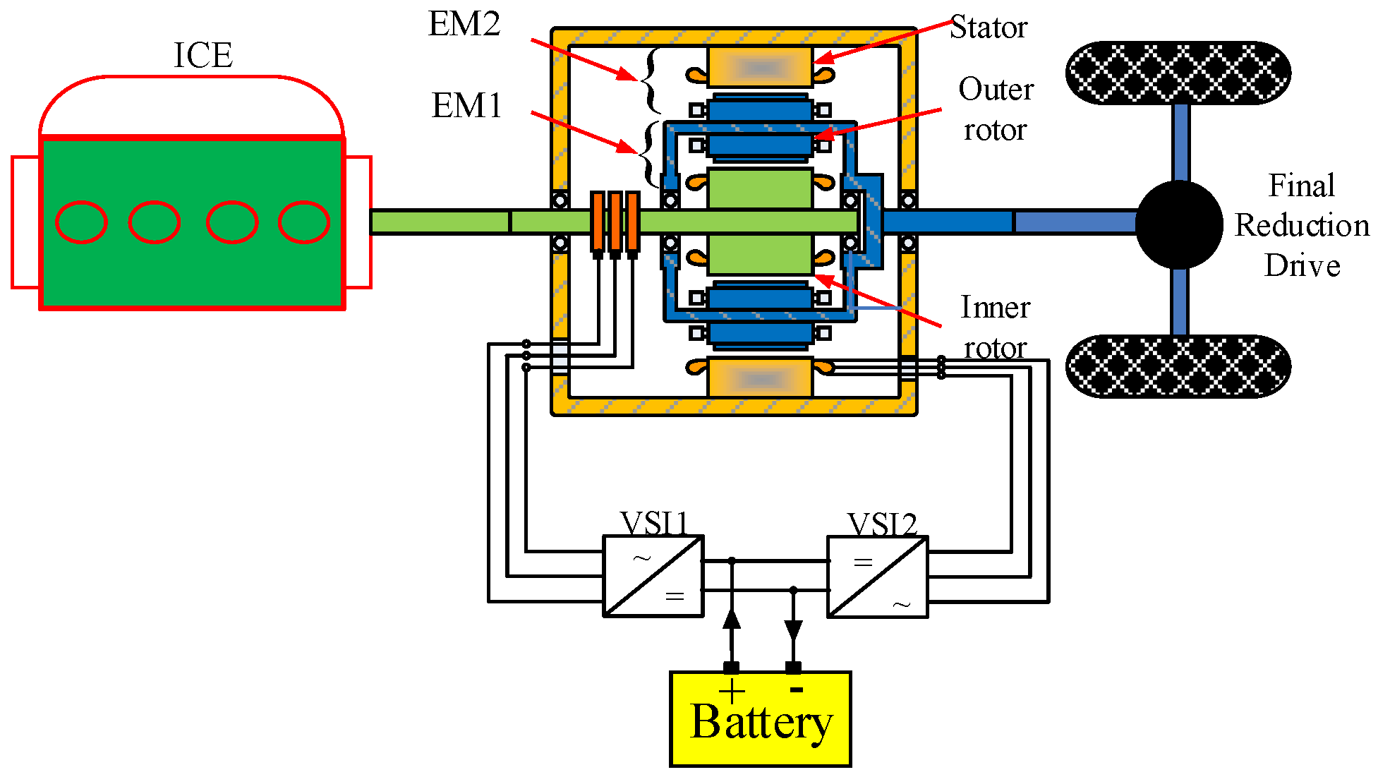
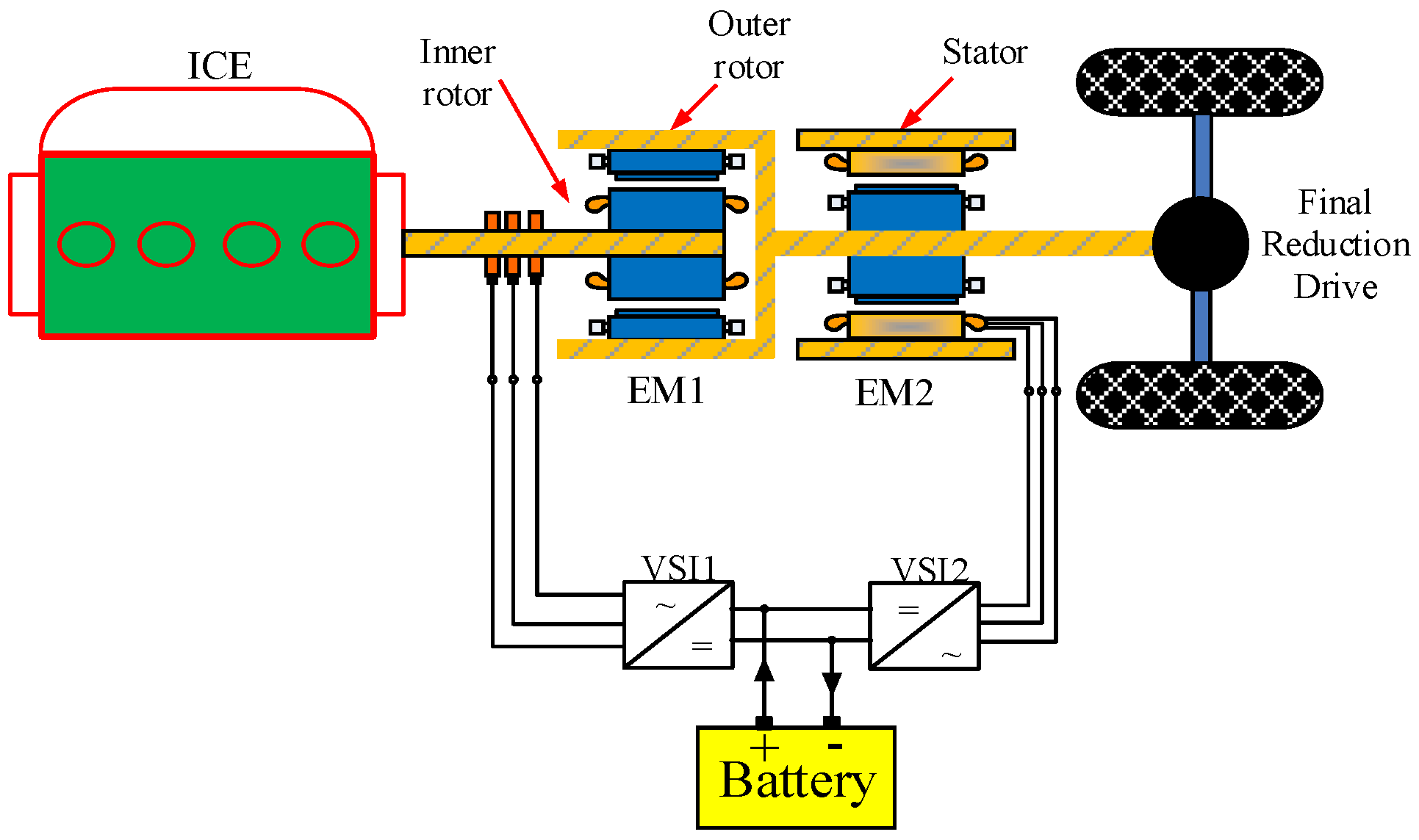
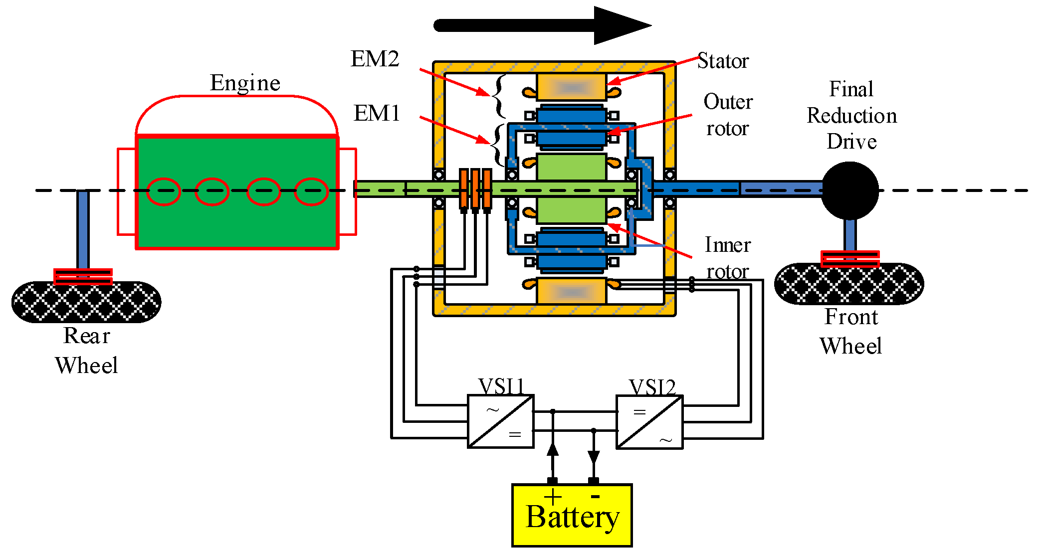
The power transmission topology and split-type power transmission topology of a hybrid electric vehicle (CSM-HEV) based on composite structure motor are shown in
Figure 1 and
Figure 2. The inner rotor of CSM (EM1) is connected to the output shaft of the internal combustion engine (ICE), and the outer rotor is used as the common rotor of EM1 and external motor (EM2) and is connected to the main reducer. ICE can be decoupled from the road and keep working in an optimal working state by controlling EM1. EM2 can be adjusted to meet the requirements of the road load. In the hybrid power state, it can realize CVT mode, driving power generation mode, auxiliary driving mode. In the pure electric state, it can realize single-motor and dual-motor driving modes.
The regenerative braking system is an important system in CSM-HEV which helps to improve the fuel economy of the vehicle and improve the cruising range of the hybrid vehicle. This paper divides the regenerative braking process into four different modes, engine-motor coordinated braking (EMCB), single-motor braking mode (SMB), dual-motor braking mode (DMB) and mechanical braking mode (MB); EMCB and DMB are firstly proposed in this paper. They are of great significance for improving the braking performance of hybrids. The details of the four braking modes are as follows:
- (1)
Engine-motor coordinated braking (EMCB)
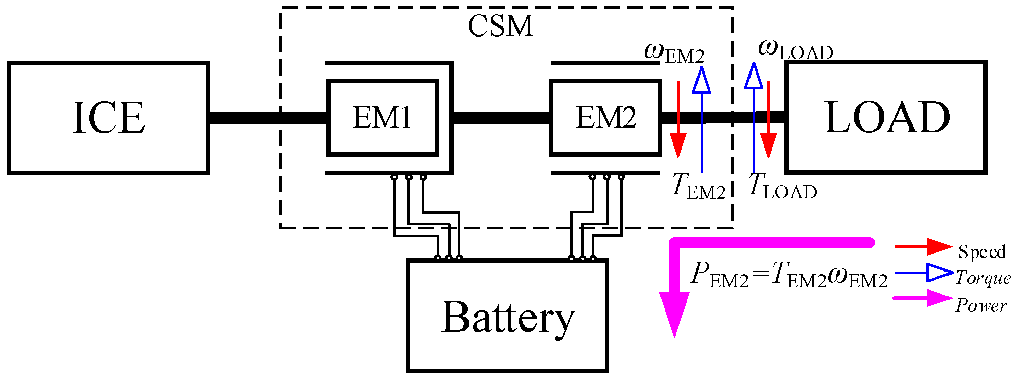
The characteristic of EMCB is that it can still keep the internal combustion engine working in the best running state during the regenerative braking process, thereby improving the fuel economy of CSM-HEV. The relationship of the torque and speed of the system is shown in the Equation (1):
In EMCB, the speed of EM2 is proportional to the vehicle speed, and the speed of EM1 is the difference between the speed of ICE and EM2. There are some special situations in the EMCB mode. When the vehicle speed is too high or the braking intensity is too large, EM1 cannot work in the optimal state or EM2 needs to provide a larger torque. Then, ICE needs to shut down or run at idle state. EM1 does not work and regenerative braking force is completely provided by EM2. The control idea is that if the required braking force is less than the maximum braking torque of EM2, the braking force is completely provided by EM2, and if the required braking force is greater than the maximum braking torque of EM2, EM2 provides the maximum regenerative braking force, and the insufficient braking force is provided by the mechanical braking force. The power flow in EMCB is shown in
Figure 3:
- (2)
Single-motor braking (SMB)
In SMB, ICE and EM1 do not work, and EM2 works only in the power generation state to provide regenerative braking force. This mode is the same as the regenerative braking mode of the pure electric vehicle, and the control method is relatively simple. The power flow analysis in SMB is shown in
Figure 4:
- (3)
Dual-motor braking (DMB)
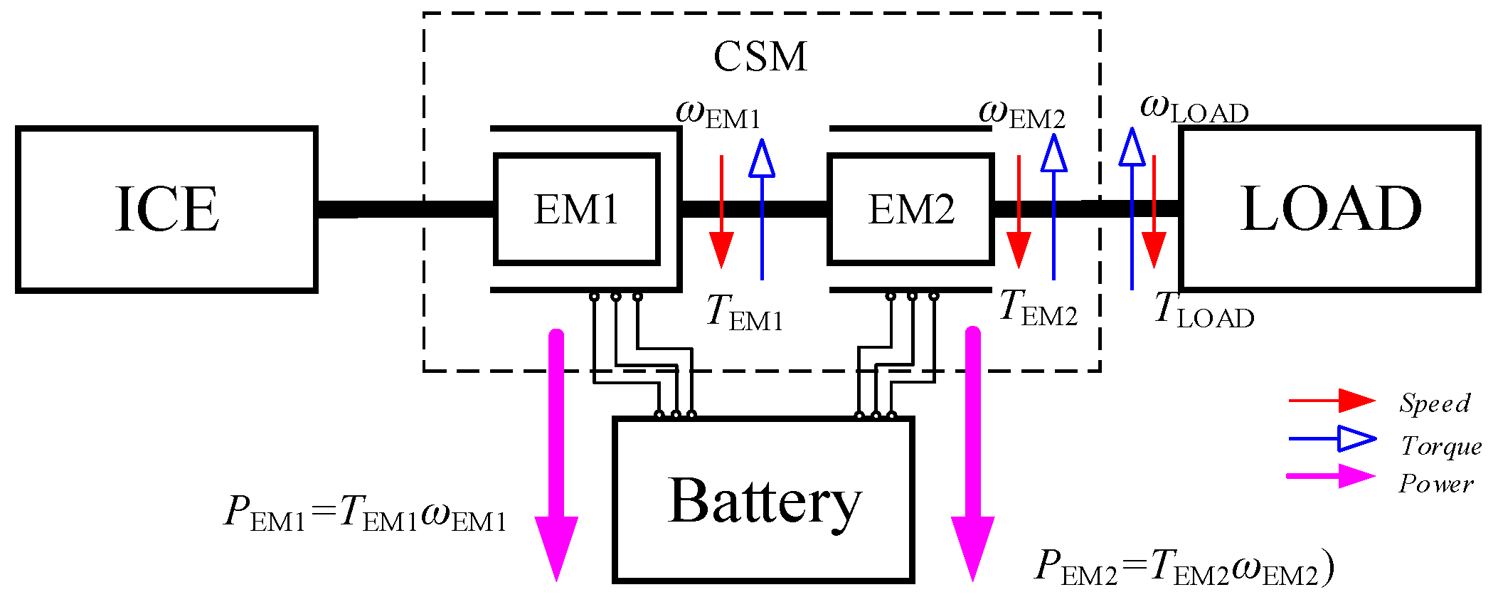
DMB mode is another important mode of CSM-HEV. Its advantage is that it uses EM1 to supplement the insufficient regenerative braking force. In ordinary electric vehicles and hybrid electric vehicles, the insufficient braking force is usually supplemented by mechanical brakes. Therefore, DMB mode can effectively improve the energy recovery efficiency. Because the motor can quickly respond to torque changes, DMB can also improve the coordination of system operation.
In DMB, the regenerative braking torque of the dual motors acts on the outer rotor in the same direction at the same time. The relationship of the torque and speed of the system is shown in the Equation (2) and the power flow analysis of DMB mode is shown in
Figure 5:
- (4)
Mechanical braking (MB)
When the vehicle speed is low, the braking intensity is emergency braking or the battery SOC is high, the efficiency and safety of the regenerative braking process are poor. At this time, the braking force is purely provided by mechanical braking, and EM1 and EM2 do not work, disconnecting the power transmission between the internal combustion engine and the road load.
3. ABS in CSM-HEV
The ABS can ensure that the wheels are not locked during braking and it can improve the vehicle’s directional stability and steering maneuverability, and shorten the braking distance. It is an important system to ensure the safety of braking process. It is an important research content to coordinate the braking force distribution in the braking process considering the braking safety of the vehicle and the efficiency of the regenerative braking system at the same time. The coordinated control of the regenerative braking system and the ABS in CSM-HEV has particularity and superiority.
3.1. ABS
This paper takes the driving shaft of CSM-HEV as the research object and the motion of the vehicle is shown in Equation (3):
where
m is the curb weight of the car,
is the deceleration,
Fbrake is the braking force of the wheels, and
Fresist is the driving resistance (driving resistance is the resistance under driving conditions, which is ground braking force, the resistance here is only air resistance and ramp resistance),
Iw is the rotational inertia of the driving wheel,
Tbrake is the braking torque,
rw is the rolling radius of the driving wheel,
v and
ω are, respectively, the velocity and wheel speed,
S is the slip rate indicating the proportion of the slip component in the wheel motion. When the slip rate is 100%, the wheel is completely locked and loses its steering ability which is a dangerous state. ABS need to adjust the braking force in real time to ensure that the slip rate during the braking process is kept within the ideal range to ensure the safety of the brake and shorten the braking distance.
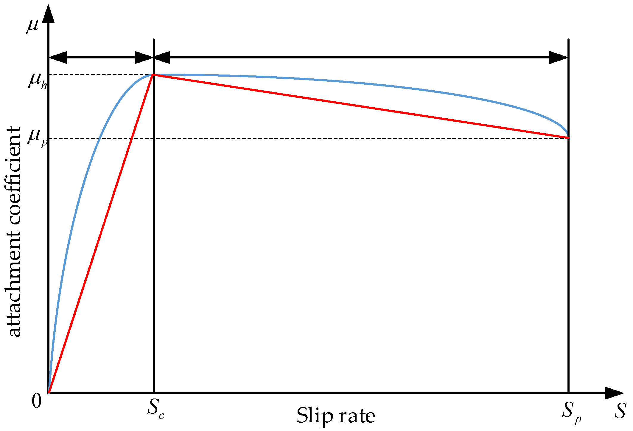
In this paper, the slip curve can be approximated linearly as shown in the following Equation (4) and
Figure 6.
where
μ is the adhesion coefficient of the road,
μh is the peak braking force coefficient,
μp is the braking force coefficient when the wheel is fully locked.
Sh is the best slip rate. The parameters of different adhesion coefficients are shown in
Table 1:
3.2. ABS in Different Braking Modes
In EMCB, EM2 needs to overcome the output torque of ICE and provides the regenerative braking torque. The motion equation at this time is shown in Equation (5):
where
Fbrake_f and
Fbrake_r are the ground braking forces acting on the front and rear wheels, respectively,
TEM1,
TEM2 and
TM are braking torque of EM1, EM2 and mechanical braking, respectively,
is is the transmission ratio of main deceleration, subscript
f and
r, respectively, indicate the corresponding parameters of the front and rear wheels.
The control of ABS and EMCB needs to adjust the torque and speed of CSM and ICE to meet the slip rate corresponding to the peak adhesion rate of the wheel slip rate, so as to achieve the purpose of braking safety. The braking system at this time is a complex system with multiple control objects. There are various control methods for the control objects. In this paper, the operation efficiency of the system is taken as the control goal to control ICE and CSM. The equivalent efficiency model in EMCB mode is shown in Equation (6):
where
ηequa is the equivalent efficiency of the system,
ηEM1 and
ηEM2 represent the efficiency of EM1 and EM2.
In DMB, ICE does not work and the regenerative braking force is provided by EM1 and EM2. Compared with the regenerative braking of ordinary hybrid vehicles, no mechanical braking force is required and the response speed of mechanical braking and electric braking is different. Therefore, the control coordination of ABS is poor, while in DMB, the coordinated braking control of ABS and the regenerative braking system only needs to coordinate the electric braking torque of EM1 and EM2, so the control coordination of the ABS is stronger. The motion equation in DMB mode is shown in Equation (7):
The coordinated control of regenerative braking and ABS in DMB needs to coordinate the regenerative braking force of EM1 and EM2 to ensure that the vehicle slip rate remains at the target value. The operating efficiency is used as the control target to adjust the regenerative braking force of CSM. The equivalent efficiency of the regenerative braking system in DMB is shown in Equation (8):
3.3. Evaluation of Hybrid Vehicle Energy Recovery Performance in CSM-HEV
The evaluation of energy recovery performance of the new braking mode proposed in this paper is slightly different from that of ordinary hybrid vehicles.
Figure 7 is the schematic diagram of energy flow in the regenerative braking process of two new braking modes.
In DMB, the motor converts the energy recovered during the braking process into electrical energy and stores it in the battery. Therefore, the regenerative braking performance of the DMB can be evaluated by the efficiency of the braking energy recovery which is similar to that in ordinary HEV [
19,
20]. As shown in Equation (9), the braking energy recovery efficiency of the DMB mode is the ratio of the energy recovered by CSM to the recoverable vehicle energy. Where
ηdmb is the braking energy recovery efficiency in the DMB mode,
Eem1 and
Eem2 are, respectively, the energy recovered by EM1 and EM2;
Ebraking is the recoverable braking energy.
In EMCB, due to the influence of ICE, there are two paths for energy recovery. On the one hand, ICE energy is recovered through EM1 and EM2. On the other hand, the braking energy is recovered through EM2. In this paper, the comprehensive energy recovery rate and braking energy recovery rate are used to evaluate the energy recovery performance in EMCB. The comprehensive energy recovery rate is all the energy recovered through EM1 and EM2 to the engine output energy and braking recoverable braking energy. The ratio is defined and shown in Equation (10). The braking energy recovery efficiency is the ratio of the braking energy recovered by EM2 to the braking energy recoverable by the vehicle and is shown in Equation (11). In which
ηsys is the comprehensive energy recovery rate,
Eice is the output energy of ICE,
ηsys is the braking energy recovery efficiency,
Eem1input and
Eem2input is the input energy of EM1 and EM2.
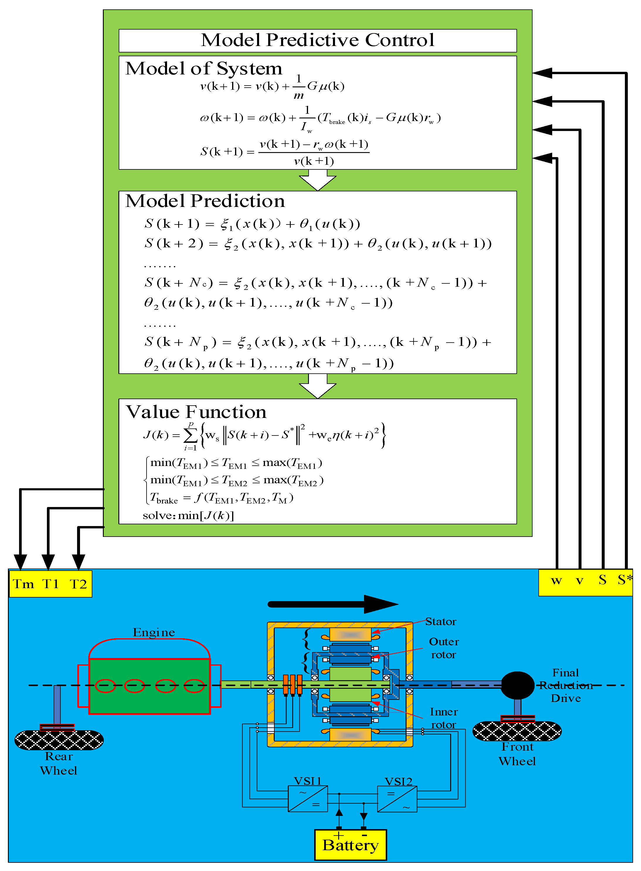
4. Coordinated Control Strategy of Regenerative Braking System and ABS
There are two important problems in the coordinated control of the regenerative braking system and ABS in CSM-HEV. One issue is the distribution of braking force of the front and rear wheels. Another issue is the braking force distribution that combines optimal system efficiency and a target slip rate.
4.1. Braking Force Distribution of Front and Rear Axles
The vehicle model studied in this paper is a 1/2 car model. As shown in
Figure 8, the braking force is provided by each wheel in the front and rear, and the vehicle only moves longitudinally.
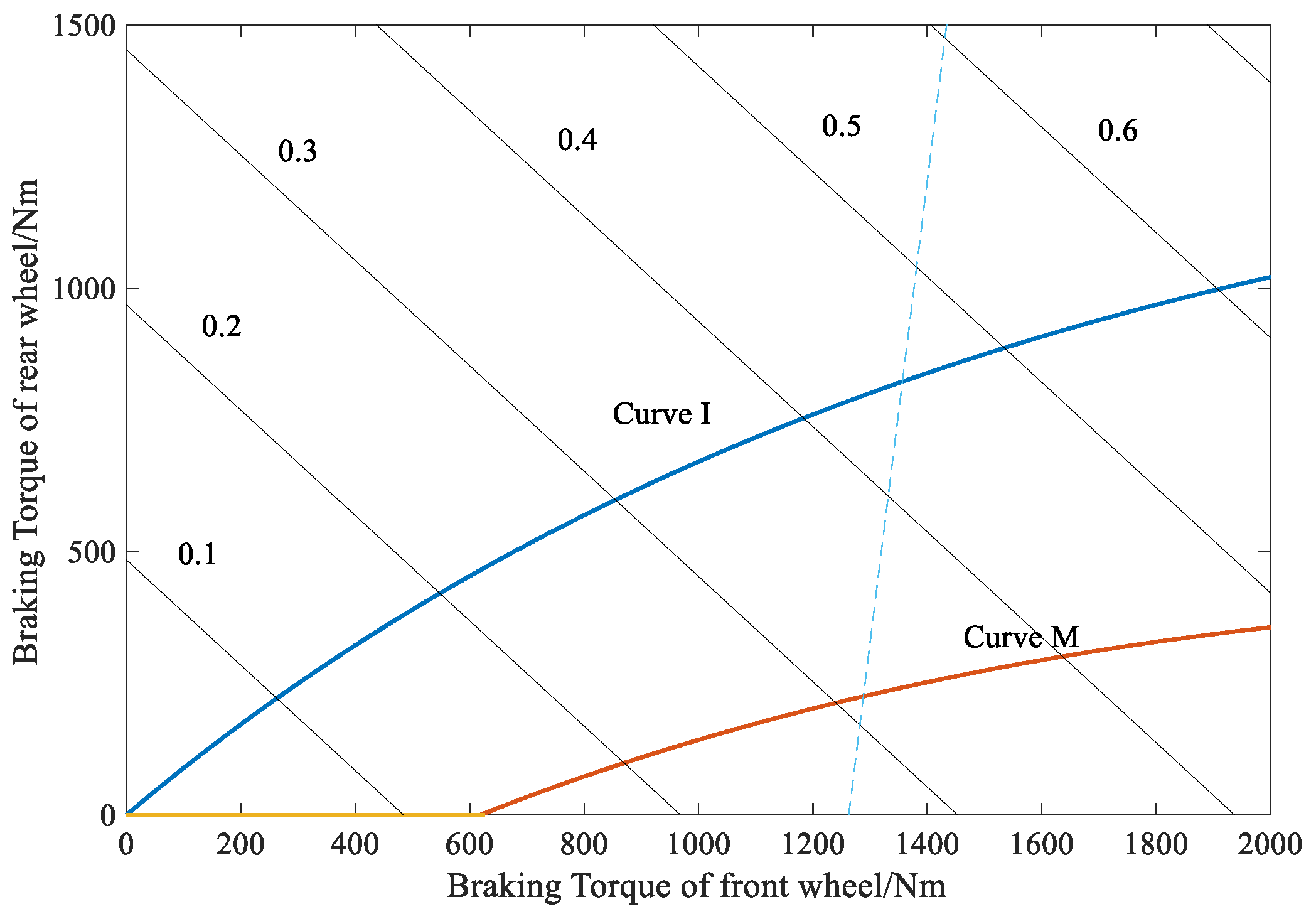
During the braking process, the front and rear wheels are locked at the same time, which is beneficial to the use of adhesion conditions and the direction stability of the car during braking. At this time, the relationship curve between the front and rear brake braking forces is often called the ideal braking force distribution curve, also called I curve. The mathematical expression of the I curve is shown in Equation (12):
where
Tμ1 and
Tμ2 are the braking torque of the front and rear wheel,
φ is the ground adhesion coefficient,
G is the vehicle curb weight, and
a and
b are the distances from the center of gravity of the vehicle to the front and rear axle.
For front driving vehicles, in order to improve the braking force distribution curve, the ECE braking regulations can be used to restrict the rear wheel braking. When meeting the braking ECE regulations, the front wheels can be supplied with more regenerative braking force. The distribution curve is often referred to as the curve M. Since more braking force is distributed to the driving wheels, the efficiency of regenerative braking can be improved. The distribution relationship of the braking force of the front and rear brakes of the M curve is shown in Equation (13):
where
L is the wheelbase,
hg is the height of the center of gravity and
z is the braking intensity. In this paper, curve I is used to distribute the braking force of the front and rear axles. The distribution curve is shown in
Figure 9.
4.2. Regenerative Braking Force Distribution Based on Model Predictive Control
The coordinated control of regenerative braking and ABS in this paper is a multi-objective control problem, and the system has typical characteristics of nonlinearity. There are many advanced control methods [
21,
22] to deal with the problem. Among them, model predictive control is a proper and convenient control method and is adopted in this paper to ensure braking safety and system operating efficiency. The flow of regenerative braking force distribution based on model predictive control is shown in
Figure 10:
The establishment of a prediction model requires the establishment of a discretized state equation of the system. Now the equation of the car’s motion in Equation (3) is written as a discrete form, as shown in Equation (14):
where k is the sampling time,
TS is the sampling step. The definitions of state variables, control variables, and optimization variables are shown in Equation (15). The state variables are vehicle speed and front and rear wheel speeds. The system control variables are the braking torque CSM and the rear axle mechanical braking torque; the variable is the slip ratio of the front and rear wheel.
The constraints on the control variables in the solution process of the predictive model are as shown in Equation (16):
In this paper, the braking torque is distributed for the purpose of ensuring the optimal slip rate of the brake and the optimal operating efficiency of the system. The equivalent efficiency of the system is written in discrete form as shown in Equation (17):
In EMCB, ICE runs on the optimal fuel consumption curve and the torque is the same as EM1 torque. In DMB, the speeds of EM1 and EM2 are the same and related to the wheel speed. The relationship between the system speed in EMCB and DMB are shown in Equations (18) and (19), respectively:
where
ωf is the wheel speed, and g (
T) is a function of the engine speed and the optimal torque on the optimal fuel consumption curve. The equivalent efficiency model can be expressed as Equation (20):
Let
Np be the prediction step and
Nc the control step. According to the system’s discrete model and equivalent efficiency model, the prediction models of slip rate and equivalent efficiency can be written as Equations (21) and (22):
where
S(k + i) is the predicted value of slip rate at time k + i,
ζi (
x,
u) is the relationship between state variable, control variable and slip rate optimization variable at time k + i,
θi (
u) is the relationship between state variables, control variables and equivalent efficiency optimization variables at time k + i.
According to the above prediction model, the evaluation function of the prediction model to ensure the optimal slip rate and the operating efficiency is shown in Equation (23):
where
p is the model prediction step,
i is the model control step,
ws is the target weight of slip rate,
we is the target weight of system efficiency, and
wb is the balance coefficient between the efficiency optimization target and the slip rate optimization target. To ensure that the double target error is within the same magnitude, the balance factor is defined as
wb =
S*/
η*.
5. Simulation and Analysis
In this paper, the regenerative braking simulation system for CSM-HEV is established. The model predictive control algorithm is used as a controller to ensure the slip rate of the brake and the equivalent efficiency. This article mainly carried out the following three aspects of simulation, the important simulation parameters used are shown in
Table 2 and
Table 3.
Simulation 1: To verify the coordinated control performance of the regenerative braking system and ABS based on model predictive control in EMCB and compare with the ordinary braking mode.
Simulation 2: To verify the coordinated control performance of the regenerative braking system and ABS based on model predictive control in DMB and compare with the ordinary braking mode.
5.1. Simulation 1
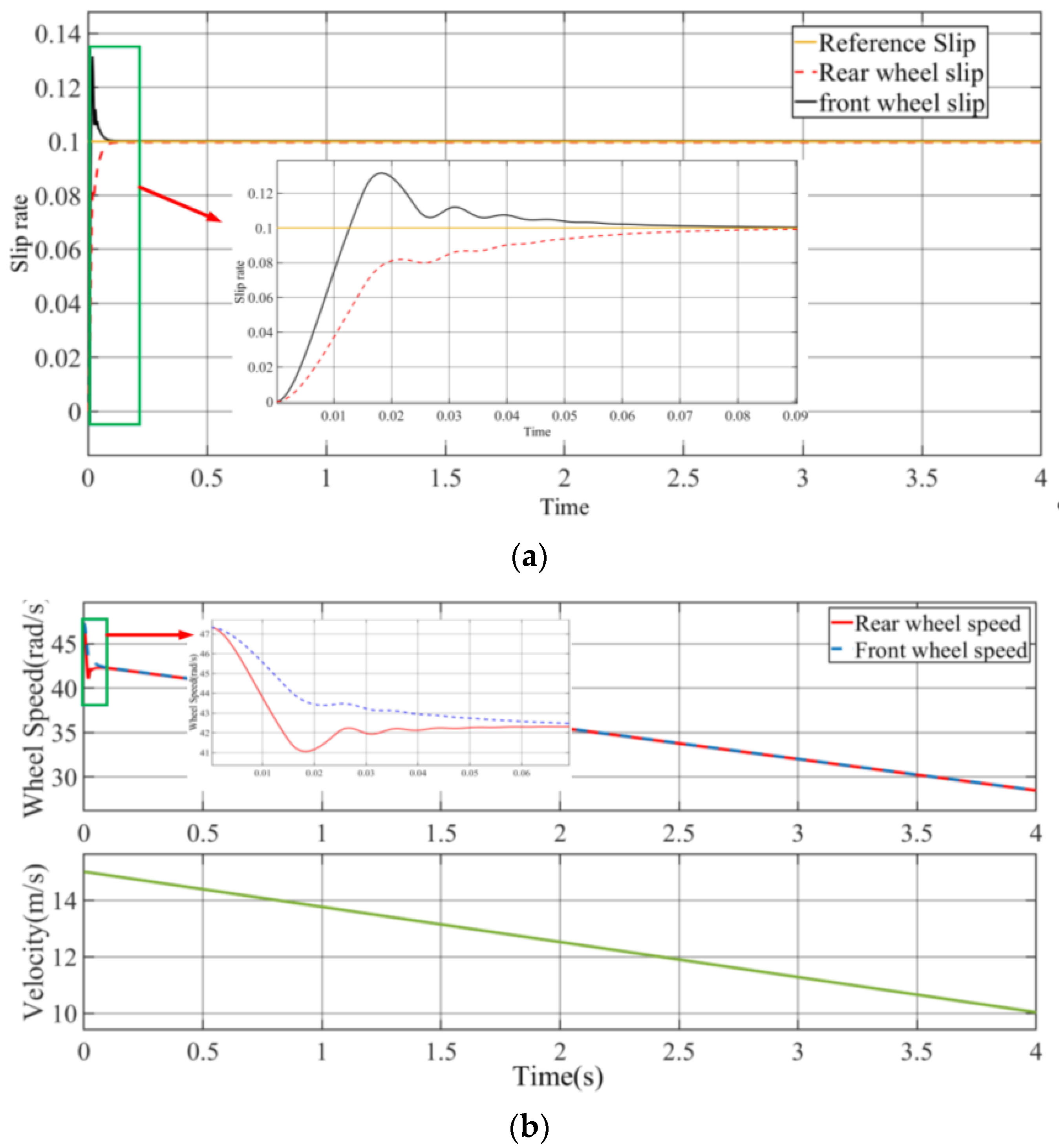
The simulation conditions for Simulation 1 are that vehicle is braking on a wet soil pavement, the target slip rate is set to 0.1, the weight of the slip rate target is 1, the weight of the equivalent efficiency target is 0.01, the initial vehicle speed is 15 m/s, the simulation duration is 4 s, and the braking mode used is the EMCB mode. Based on the above simulation settings, the simulation results are shown in
Figure 11:
Figure 11 shows that the control algorithm designed in this paper enables the vehicle to track the target slip. Evaluated by a 2% error band, the adjustment time of the front wheel slip rate is 53 ms and the adjustment time of the rear wheel slip rate is 61 ms; the errors of the actual slip rate of the front and rear wheels and the target slip rate under steady state are 0.22% and 0.27%, respectively. Within 4 s, the vehicle velocity is reduced from 15 to 10 m/s. It can be seen from
Figure 11d that in the initial stage of braking, the efficiency of EM2 is 85% while the efficiency of EM1 is 77%. As the vehicle speed decreases, the speed of EM2 decreases and the efficiency reduces; meanwhile, the speed of EM1 increases and the efficiency goes upward.
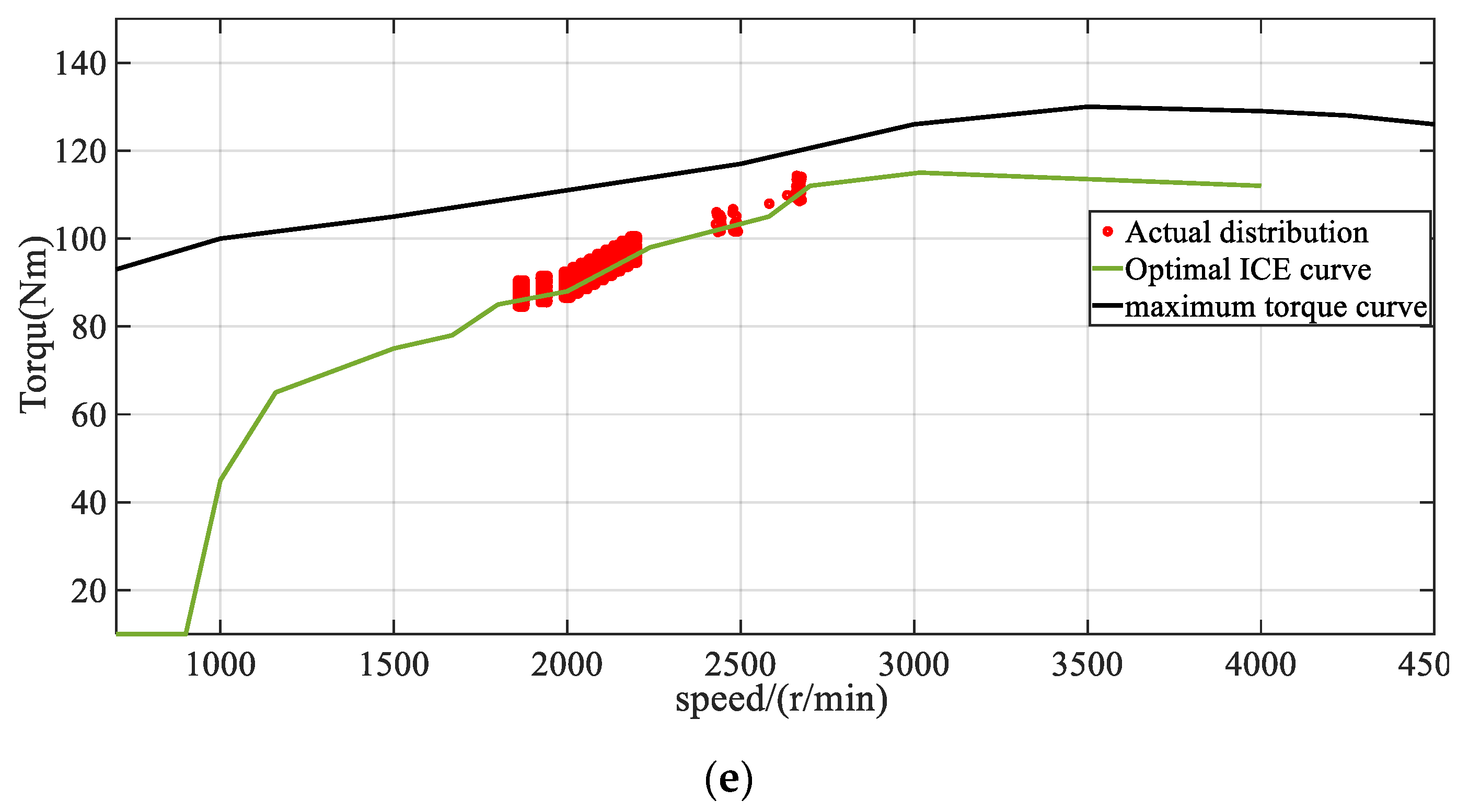
Figure 11e shows that with EMCB based on model predictive control, the engine can run near the optimal curve of the engine. This is the advantage of EMCB compared to the traditional control. The switching frequency and the energy loss of ICE can be reduced.
The energy recovery efficiency under different efficiency weights is shown in
Table 4. When efficiency weights are not considered, the braking energy recovered during the braking process is 41.56 kJ, the braking recovery efficiency is 46.99% and the comprehensive energy recovery efficiency is 61.48%. With the increase in the efficiency weight, the comprehensive energy recovery efficiency and the braking energy recovery efficiency show the upward trend.
At present, the regenerative braking control of CSM-HEV is the same as that of ordinary hybrid vehicles. When the vehicle enters the braking mode from the hybrid drive state, ICE is in the idle state and EM2 provides the regenerative braking force. The simulation conditions of the ordinary braking mode are the same as those in EMCB. The ordinary mode uses a model predictive control algorithm based on slip rate and its braking simulation performance is shown in
Figure 12.
Evaluated by the 2% error band, the adjustment time of the front wheel slip rate is 62 ms in the normal braking mode and the adjustment time of the rear wheel slip rate is 71 ms. The errors between the actual slip rate and target slip rate of the front and rear wheels under steady state are 0.19% and 0.29%, respectively.
In terms of energy recovery efficiency, the energy recovered during the braking process is 42.02 kJ in the normal braking mode and the braking energy recovery efficiency is 47.49%, which is slightly lower than that in EMCB. In EMCB, the output energy of the engine is recovered into the battery through CSM. In the ordinary braking mode, the engine is in idle state and the output energy is totally lost. When converting to the fuel quantity through the universal characteristic curve, the loss of fuel quantity in EMCB is 1.146 g, while fuel loss in the normal braking mode is 1.78 g. Therefore, the fuel consumption loss in EMCB is reduced by 35.6% compared to the ordinary braking mode.
5.2. Simulation 2
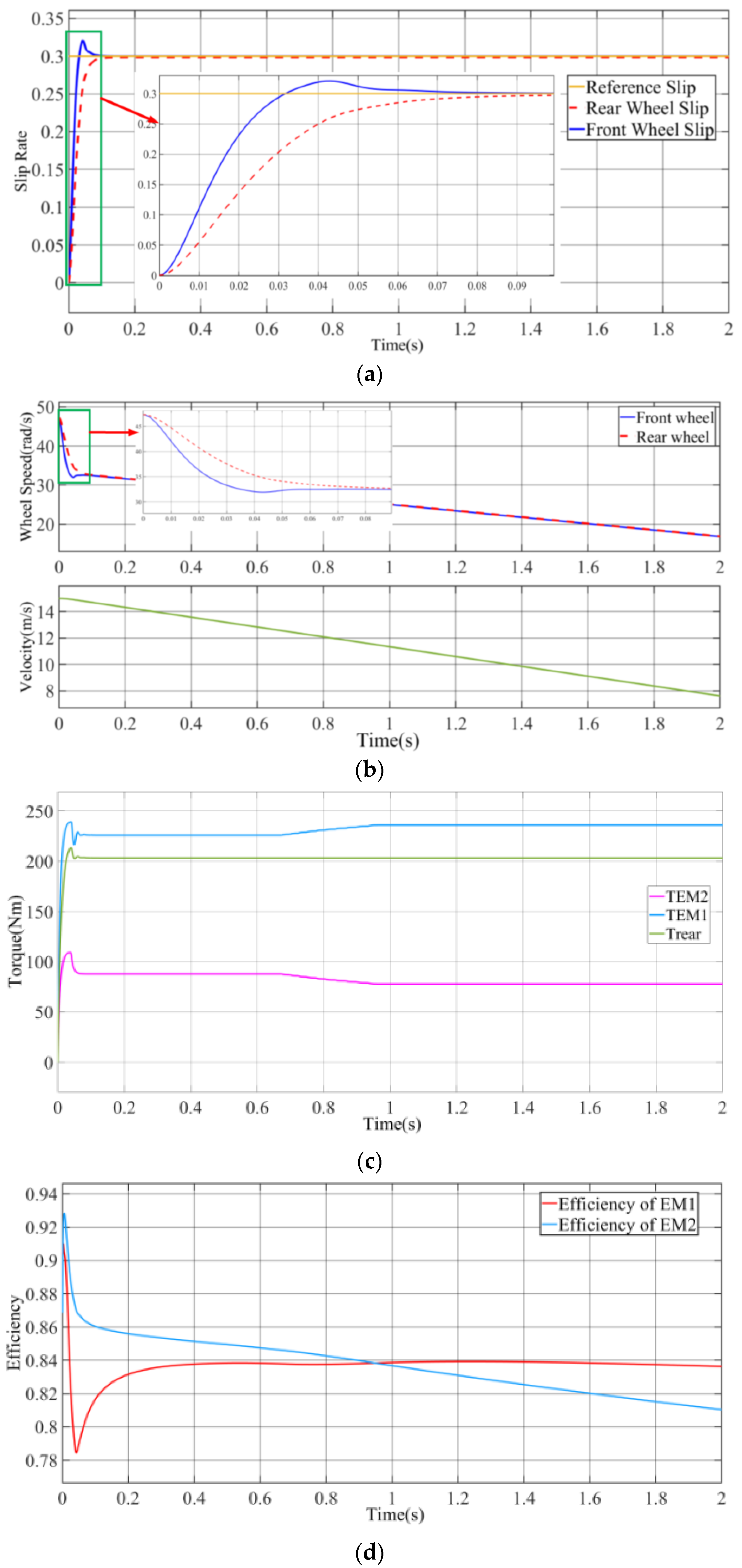
The simulation conditions for Simulation 2 are that the vehicle is braking on a wet soil pavement, the target slip rate is set to 0.3, the weight of the slip rate target is 1, the weight of the equivalent efficiency target is 0.01, the initial speed is 15 m/s, and the simulation duration is 2 s. Based on the above simulation settings, the simulation results are shown in
Figure 13.
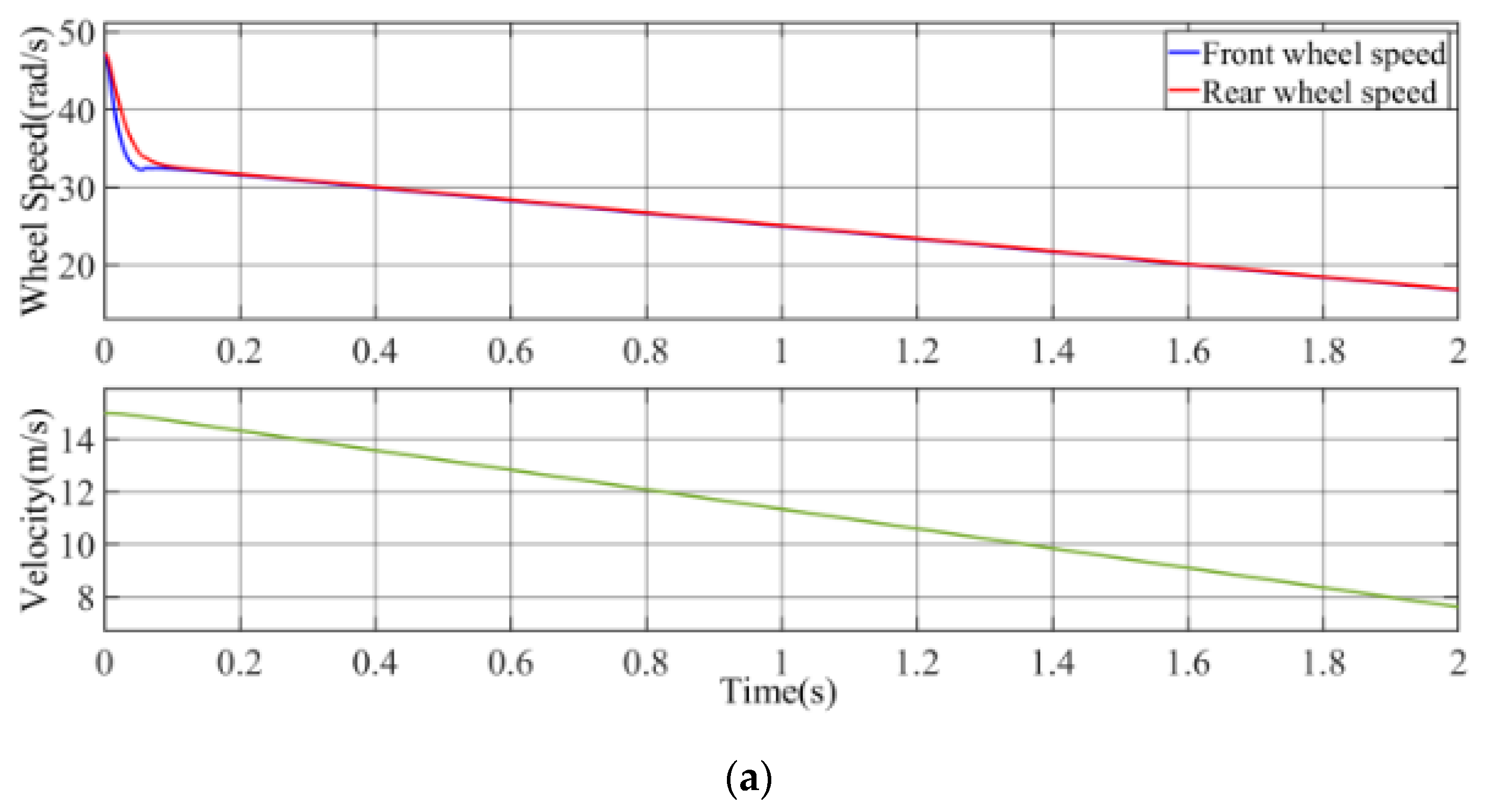
Figure 13 shows that the control algorithm enables the vehicle to successfully track the target slip. Evaluated by the 2% error band, the adjustment time of the front wheel slip rate is 56 ms and the adjustment time of the rear wheel slip rate is 79 ms; the error between the actual slip rate of the front and rear wheels and the target slip rate are 0.13% and 0.75%, respectively, under steady state. Vehicle velocity is reduced from 15 to 7.6 m/s within 2 s.
Figure 13d shows that the efficiency of EM1 is above 79% and the efficiency of EM2 is above 81%.
The braking energy recovery efficiency under different efficiency weights is shown in
Table 5. When efficiency weights are not considered, the braking energy recovered during the braking process is 42.36 kJ and the braking energy recovery efficiency is 46.14%. As the efficiency weight increases, the braking energy recovery efficiency also increases.
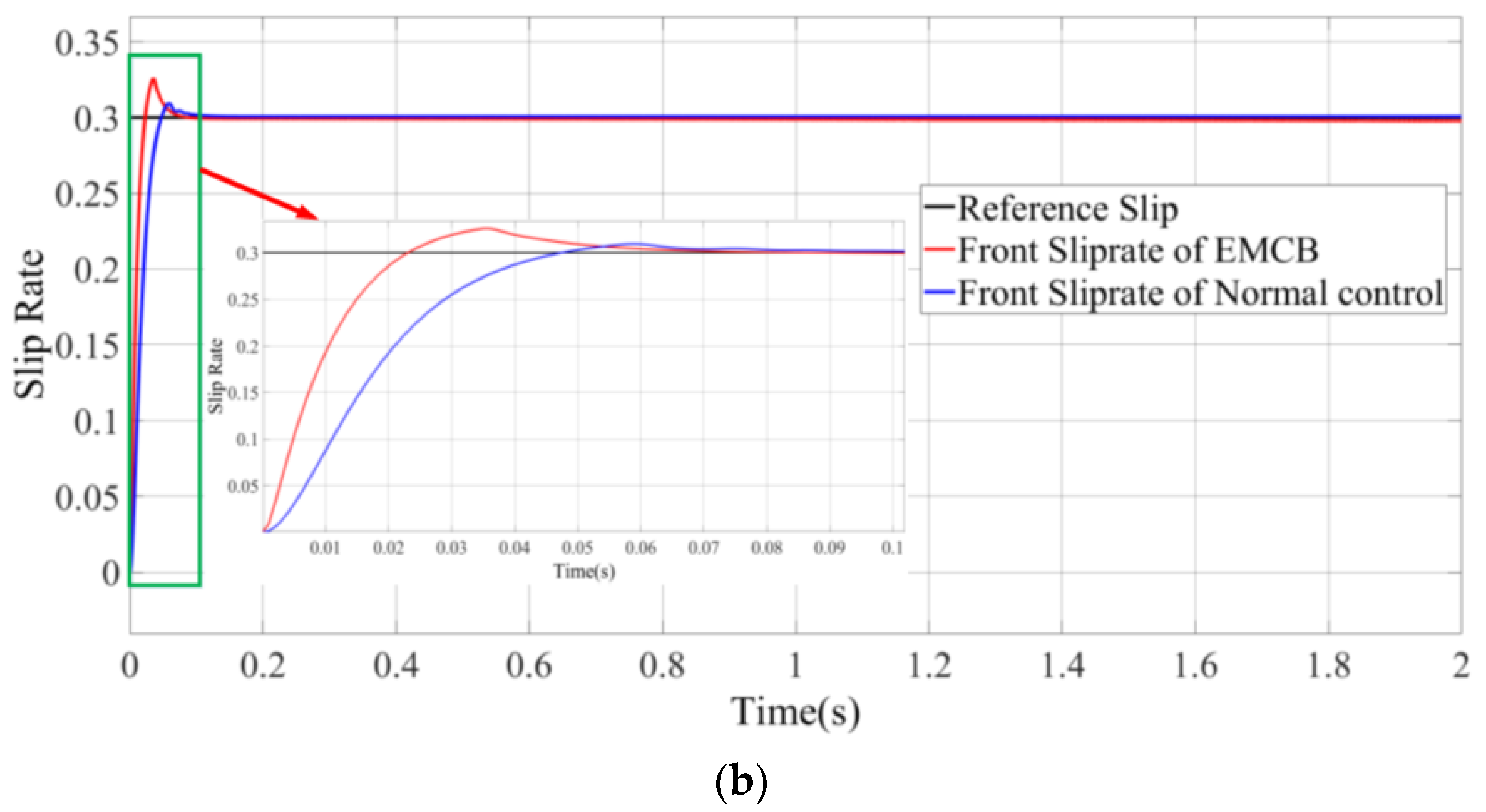
In electric driving mode, the regenerative braking strategy of CSM-HEV is the same as that of ordinary hybrid vehicles and only EM2 is used in regenerative braking. The simulation conditions based on the ordinary regenerative braking control are the same as those in DMB. The braking performance of the ordinary braking mode is shown in
Figure 14. The results show that the normal braking mode can follow the target slip rate during the braking process. Evaluated by the 2% error band, the adjustment time of front wheel slip rate is 68 ms. Since the ordinary braking mode is the coordinated control of the electric braking and mechanical braking, while the DMB is the coordinated control of two motors, the adjustment time is 12 ms faster than that of the ordinary braking mode. The energy recovery efficiency is 29.6% in normal control while the energy recovery efficiency of DMB is 46.39%. Due to the use of EM1 to supplement the regenerative braking force in DMB, the energy recovery efficiency is increased by 16.79%.
6. Conclusions
In this paper, two new braking modes, EMCB and DMB, are firstly proposed and the coordination control of regenerative braking system and ABS is researched. In order to ensure the optimal slip rate of the vehicle and the optimal equivalent efficiency of CSM during the regenerative braking process, the model predictive control algorithm is proposed to control the new braking modes and regenerative braking performance evaluation indicators for two new braking modes are established. Through the simulation in Simulink, this paper arrives at the following important conclusions:
(1) Under the control algorithm designed in this paper, EMCB and DMB can make the vehicle track the target slip rate and ensure the safety of braking.
(2) EMCB can keep ICE working in the best state during the regenerative braking process, thereby improving the fuel economy of CSM-HEV. Compared with the ordinary braking mode, the braking energy recovery efficiency of EMCB is similar while the fuel loss of the engine during the braking process of EMCB is reduced by 30.1% compared with the ordinary braking mode.
(3) DMB uses EM1 to supplement the insufficient regenerative braking force. Thereby increasing the braking energy efficiency. Compared with the ordinary braking mode, DMB can increase the braking energy recovery efficiency by 16.78% and the response time to the target slip rate is reduced by 12 ms.
Author Contributions
Conceptualization, C.Z.; methodology, C.Z.; software, X.Z.; validation, H.H.; formal analysis, C.Z.; investigation, C.Z.; resources, C.Z.; data curation, C.Z.; writing—original draft preparation, C.Z.; writing—review and editing, C.Z.; visualization, C.Z.; supervision, Q.X.; project administration, C.Z.; funding acquisition, C.Z. All authors have read and agreed to the published version of the manuscript.
Funding
This research was supported by the Chongqing Science and Technology Commission of China under Project No. cstc2018jcyjA3148; graduate scientific research and innovation foundation of Chongqing, China under Grant No. CYS1807; graduate research and innovation foundation of Chongqing, China under Grant No. CYB18009.
Conflicts of Interest
The authors declare no conflict of interest.
References
- Zhang, J.; Kong, D.; Chen, L. Optimization of control strategy for regenerative braking of an electrified bus equipped with an anti-lock braking system. Proc. Inst. Mech. Eng. Part D J. Automob. Eng. 2012, 226, 494–506. [Google Scholar] [CrossRef]
- Peng, D.; Zhang, Y.; Yin, C.L. Combined control of a regenerative braking and antilock braking system for hybrid electric vehicles. Int. J. Automot. Technol. 2008, 9, 749–757. [Google Scholar] [CrossRef]
- Solliec, L. Regenerative Braking Optimization and Wheel Slip Control for a Vehicle with In-Wheel Motors. IFAC Proc. Vol. 2013, 46, 542–547. [Google Scholar] [CrossRef]
- Zhang, J.; Yin, C.; Zhang, C. Design and Analysis of Electro-mechanical Hybrid Anti-lock Braking System for Hybrid Electric Vehicle Utilizing Motor Regenerative Braking. Chin. J. Mech. Eng. 2009, 22, 42–49. [Google Scholar] [CrossRef]
- Chu, L.; Chen, J.; Yao, L. Regenerative Braking System Pressure Control Calculation Based on ABS Hydraulic Model. Appl. Mech. Mater. 2012, 201, 433–437. [Google Scholar] [CrossRef]
- Wang, B.; Huang, X.; Wang, J.; Guo, X.; Zhu, X. A robust wheel slip ratio control design combining hydraulic and regenerative braking systems for in-wheel-motors-driven electric Vehicles. J. Frankl. Inst. 2015, 352, 577–602. [Google Scholar] [CrossRef]
- Qiu, C.; Wang, G.; Meng, M. A novel control strategy of regenerative braking system for electric vehicles under safety critical driving situations. Energy 2018, 149, 329–340. [Google Scholar] [CrossRef]
- Wu, J.; Wang, X.; Li, L.; Du, Y. Hierarchical control strategy with battery aging consideration for hybrid electric vehicle regenerative braking control. Energy 2018, 145, 301–312. [Google Scholar] [CrossRef]
- Hoeijmakers, M.J.; Ferreira, J.A. The electric variable transmission. IEEE Trans. Ind. Appl. 2006, 42, 1092–1100. [Google Scholar] [CrossRef]
- Hoeijmakers, M.J.; Rondel, M. The electrical variable transmission in a city bus. In Proceedings of the 2004 IEEE 35th Annual Power Electronics Specialists Conference (IEEE Cat. No.04CH37551), Aachen, Germany, 20–25 June 2004; IEEE: New York, NY, USA, 2004. [Google Scholar]
- Glowacz, A. Diagnostics of Synchronous Motor Based on Analysis of Acoustic Signals with the use of Line Spectral Frequencies and K-nearest Neighbor Classifier. Arch. Acoust. 2014, 39, 189–194. [Google Scholar] [CrossRef]
- Glowacz, A.; Glowacz, W.; Kozik, J.; Piech, K.; Gutten, M.; Caesarendra, W.; Liu, H.; Brumercik, F.; Irfan, M.; Khan, Z.F. Detection of Deterioration of Three-phase Induction Motor using Vibration Signals. Meas. Sci. Rev. 2019, 19, 241–249. [Google Scholar] [CrossRef]
- Xu, Q.; Cui, S. Research on the Power Management Strategy of Hybrid Electric Vehicles Based on Electric Variable Transmissions. Energies 2014, 7, 934–960. [Google Scholar] [CrossRef]
- Xu, Q.; Cui, S. Comparison Analysis of Power Management used in Hybrid Electric Vehicle based on Electric Variable Transmission. In Proceedings of the 2016 UKACC 11th International Conference on Control (CONTROL), Belfast, UK, 31 August–2 September 2016. [Google Scholar]
- Ahmed, A.; Cui, S. A Fuzzy Logic Global Power Management Strategy for Hybrid Electric Vehicles Based on a Permanent Magnet Electric Variable Transmission. Energies 2012, 5, 1175–1198. [Google Scholar]
- Cui, S.; Huang, W.; Zhang, Q. Research on Power Density Improvement Design of an HEV using Induction Machine based Electrical Variable Transmission. In Proceedings of the IEEE Vehicle Power and Propulsion Conference (VPPC), Harbin, China, 3–5 September 2008. [Google Scholar]
- Ahmed, A.; Cui, S. Control and Analysis of Regenerative Power Distribution on Electrical Variable Transmission Using Fuzzy Logic on HEV System. In Proceedings of the International Conference on Electrical Machines & Systems 2011, Beijing, China, 20–23 August 2011. [Google Scholar]
- Xu, Q.; Mao, Y.; Zhao, M. A Hybrid Electric Vehicle Dynamic Optimization Energy Management Strategy Based on a Compound-Structured Permanent-Magnet Motor. Energies 2018, 11, 2212. [Google Scholar] [CrossRef]
- Lv, C.; Zhang, J.; Li, Y. Mechanism analysis and evaluation methodology of regenerative braking contribution to energy efficiency improvement of electrified vehicles. Energy Convers. Manag. 2015, 92, 469–482. [Google Scholar] [CrossRef]
- Qiu, C.; Wang, G. New evaluation methodology of regenerative braking contribution to energy efficiency improvement of electric vehicles. Energy Convers. Manag. 2016, 119, 389–398. [Google Scholar] [CrossRef]
- Lv, C.; Zhang, J. Novel control algorithm of braking energy regeneration system for an electric vehicle during safety-critical driving maneuvers. Energy Convers. Manag. 2015, 106, 520–529. [Google Scholar] [CrossRef]
- Sanketh, S.S.; Karabasoglu, O. Regenerative Braking Control Strategy for Hybrid and Electric Vehicles Using Artificial Neural Networks. In International Conference on Engineering Applications of Neural Networks; Springer: Cham, Switzerland, 2014; Volume 459, pp. 103–112. [Google Scholar]
Figure 1.
Power transmission topology of hybrid electric vehicle based on a composite structure motor (CSM-HEV).
Figure 1.
Power transmission topology of hybrid electric vehicle based on a composite structure motor (CSM-HEV).
Figure 2.
Power transmission topology of the separated CSM-HEV.
Figure 2.
Power transmission topology of the separated CSM-HEV.
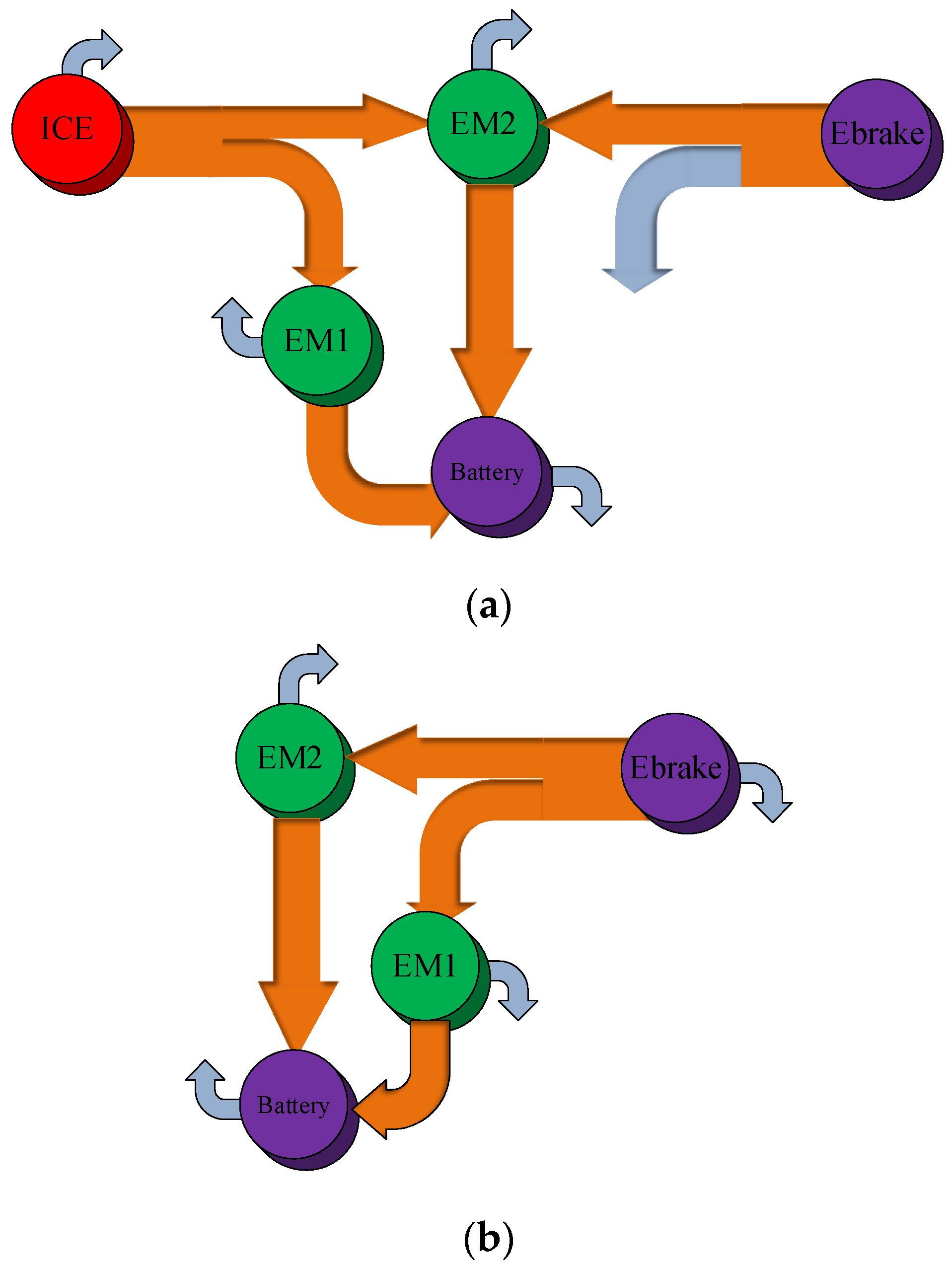
Figure 3.
Analysis of power flow in engine-motor coordinated braking (EMCB) mode.
Figure 3.
Analysis of power flow in engine-motor coordinated braking (EMCB) mode.
Figure 4.
Analysis of power flow in single-motor braking (SMB) mode.
Figure 4.
Analysis of power flow in single-motor braking (SMB) mode.
Figure 5.
Analysis of power flow in dual-motor braking (DMB) mode.
Figure 5.
Analysis of power flow in dual-motor braking (DMB) mode.
Figure 6.
Linearization of the slip rate curve.
Figure 6.
Linearization of the slip rate curve.
Figure 7.
(a) Schematic diagram of energy flow in EMCB; (b) schematic diagram of energy flow in DMB.
Figure 7.
(a) Schematic diagram of energy flow in EMCB; (b) schematic diagram of energy flow in DMB.
Figure 8.
Schematic diagram of the vehicle model.
Figure 8.
Schematic diagram of the vehicle model.
Figure 9.
Distribution curve of braking force.
Figure 9.
Distribution curve of braking force.
Figure 10.
Model prediction algorithm flow.
Figure 10.
Model prediction algorithm flow.
Figure 11.
Braking performance in EMCB: (a) slip rate variation; (b) vehicle speed and wheel speed variation; (c) braking torque variation; (d) motor efficiency variation; (e) engine operating point.
Figure 11.
Braking performance in EMCB: (a) slip rate variation; (b) vehicle speed and wheel speed variation; (c) braking torque variation; (d) motor efficiency variation; (e) engine operating point.
Figure 12.
Performance of ordinary regenerative braking mode in hybrid state: (a) slip rate variation; (b) vehicle speed and wheel speed variation.
Figure 12.
Performance of ordinary regenerative braking mode in hybrid state: (a) slip rate variation; (b) vehicle speed and wheel speed variation.
Figure 13.
Braking performance in DMB: (a) slip rate variation; (b) vehicle speed and wheel speed variation; (c) braking torque variation; (d) motor efficiency variation.
Figure 13.
Braking performance in DMB: (a) slip rate variation; (b) vehicle speed and wheel speed variation; (c) braking torque variation; (d) motor efficiency variation.
Figure 14.
Braking performance of normal braking mode in pure electric state: (a) vehicle speed and wheel speed variation; (b) comparison of slip rate.
Figure 14.
Braking performance of normal braking mode in pure electric state: (a) vehicle speed and wheel speed variation; (b) comparison of slip rate.
Table 1.
Ground adhesion coefficients of different roads.
Table 1.
Ground adhesion coefficients of different roads.
| Different Roads | SC | μh | μg |
|---|
| Dry asphalt | 0.17 | 0.9599 | 0.75 |
| Wet dirt | 0.36 | 0.4546 | 0.45 |
| Loose snow | 0.2 | 0.15 | 0.27 |
| Freeze | 0.10 | 0.1028 | 0.07 |
Table 2.
Important power system parameters for simulation.
Table 2.
Important power system parameters for simulation.
| Engine Parameters | Maximum Torque (Nm)/Corresponding Speed (r/min) | Maximum Power (kW) |
| Engine | 130/3500 | 60 |
| Motor Parameters | Maximum Torque (Nm) | Rated Speed (r/min) | Maximum Power (kW) |
| EM1 | 130 | 2000 | 30 |
| EM2 | 240 | 3000 | 60 |
Table 3.
Important vehicle parameters for simulation.
Table 3.
Important vehicle parameters for simulation.
| Vehicle Parameters | Value |
|---|
| Rolling radius (m) | 0.317 |
| Main reduction ratio | 3.59 |
| Curb quality (kg) | 1559 |
| Wheelbase (m) | 2.5 |
| Centroid height (m) | 0.569 |
| Distance from center of mass to front axle | 1.1 |
Table 4.
Comparison of energy recovery rates under different efficiency weights.
Table 4.
Comparison of energy recovery rates under different efficiency weights.
| Weights | Braking Energy (kJ) | Braking Energy
Recovery Rate (%) | Comprehensive Energy Recovery
Rate (%) |
|---|
| 0 | 88.43 | 46.99 | 61.48 |
| 0.001 | 88.43 | 47.89 | 63.62 |
| 0.01 | 88.4 | 47.89 | 63.62 |
| 0.1 | 88.17 | 47.91 | 63.65 |
| 0.2 | 87.93 | 47.92 | 63.69 |
Table 5.
Comparison of energy recovery rates under different efficiency weights.
Table 5.
Comparison of energy recovery rates under different efficiency weights.
| Weights | Energy Recovery (kJ) | Braking Energy (kJ) | Brake Energy Recovery Rate (%) |
|---|
| 0 | 43.11 | 92.24 | 46.14 |
| 0.001 | 43.18 | 93.09 | 46.39 |
| 0.01 | 43.18 | 93.03 | 46.42 |
| 0.1 | 43.19 | 92.25 | 46.77 |
| 0.2 | 43.13 | 91.53 | 47.12 |
| Publisher’s Note: MDPI stays neutral with regard to jurisdictional claims in published maps and institutional affiliations. |
© 2021 by the authors. Licensee MDPI, Basel, Switzerland. This article is an open access article distributed under the terms and conditions of the Creative Commons Attribution (CC BY) license (http://creativecommons.org/licenses/by/4.0/).


