Article

Generation of Beam Tilt through Three-Dimensional Printed Surface

1
Faculty of Science and Engineering, School of Engineering, Macquarie University, Sydney, NSW 2109, Australia
2
BENELEC Technologies, Botany, NSW 2019, Australia
*
Authors to whom correspondence should be addressed.
Electronics 2021, 10(24), 3174; https://doi.org/10.3390/electronics10243174
Submission received: 9 November 2021 / Revised: 14 December 2021 / Accepted: 16 December 2021 / Published: 20 December 2021
(This article belongs to the Special Issue The New Era of Satellite Communications, Challenges and Promises)

Abstract

:
In this paper, 3D printed surfaces are presented to study this technology’s application in generating beam tilt for the electromagnetic waves in the Ku-band. Additionally, the input source is maintained by a feed horn that is additively manufactured and is coated with copper spray paint to add conductivity, which is fed by a WR-75 waveguide. The proposed beam tilt generating surface is also referred to as a Beam Deviating Surface (BDS). There is no relative gap between the BDS and the aperture of the horn, which eventually decreased the overall antenna height. The BDS layer is able to deviate the beam for a fixed elevation angle of 22.5 and could be consequently rotated along with the rotation of the BDS prototype. The voltage standing wave ratio value is less than two over the operating frequency range, which depicts the wideband behavior. The measured and simulated radiation patterns show that we can tilt the electromagnetic waves in ranges of up to +/−22.5 with a minimum side lobe level of −5 dB at frequencies from 10 to 15 GHz. This signifies the wideband characteristic of the proposed prototype, which is achieved by Vero material from Multijet Printing that is a low-cost and rapid manufacturing 3D printing technology.

1. Introduction

Beam tilting antennas play a significant role in modern wireless communication systems with their application in radar and satellite technologies [1,2]. In 5G communication, the radiated beam could be directed to a specific location. Several designs have been presented in the literature for beam tilting [3,4,5,6]. A clover antenna is demonstrated in [3], which shows a high gain and wideband operation to prove the beam-forming capability for 5G beam tilting applications. Similarly, the use of active devices such as PIN diodes is utilized to reconfigure the radiation patterns in a frequency selective surface [4]. The analysis performed for the phase-shifting surface principle is detailed in [5], where the beam tilting is attained by transforming the phase distribution of Fabry Perot cavity antenna (FPCA) in the near-field region with the use of surfaces such as wedge-shaped dielectric lens (WSDL), discrete multi-level grating dielectric (DMGD), printed gradient surface (PGS), and perforated dielectric gradient surface (PDGS). Additionally, phased array antennas are used in a wide range of applications such as satellite communications and radars, owing to their flexible control of beam direction. However, they require higher costs because of complex feeding and phase-shifting arrangements [6]. Several studies have been conducted, describing various methods adopted for tilting the beam direction as highlighted in [7]. Most of the systems are tall, bulky and have complex geometrical configurations. Examples include, transformation optics lens [8,9], flat Luneburg lens [10,11,12], transmit array prototypes [13,14,15] and reflect arrays [16,17,18]. In order to have a reduced antenna profile for tilting the beam direction, the research is growing in the field of metasurface design. The design of those novel metasurfaces has been of prime interest, such as in [19], where the idea of a radially gradient metasurface in addition to apartial superstrate is chosen. These metasurfaces could also be designed through the use of 3D printing technology to realize the switchable phase, the so-called programmable metasurfaces [20]. The use of 3D printing technology has made high-quality mechanical prototyping fast and easy, where we can propose a novel approach for the fabrication of devices [21,22]. The approach could be useful not only for ultra-high frequency systems but also for other classes of nanosystems such as those that are introduced in the microfluidics area [23]. A pair of 3D printed stepped dielectric (SD) and dielectric wedges (DW) were fabricated by using fused deposition modeling technology, where the former can focus on the broadside beam at an offset angle of 20 , and the latter could be used to scan the antenna beam in both azimuth and elevation planes [24]. Furthermore, a pair of metasurfaces is designed to study the tilting effect of the beam for the resonant cavity antenna that is operating at a single frequency. These metasurfaces are fabricated with the particular arrangement of rectangular patches that enable the beam tilting method using near-field phase transformation [25]. Similarly, a computer numerical control (CNC) machine is used to realize phase correcting stepped dielectric phase transformers (PCSPT) and stepped dielectric phase transformers (SPT), which shows the improved antenna system that has a tilting and impedance matching bandwidth of 40.6 % from 26.5 to 40 GHz [26]. This system does not require expensive phase-shifters and distribution networks, which shows advantages in terms of tilting bandwidth, aperture efficiency and gap between the source antenna and first beam tilting surface. Additionally, a full transmission phase range of 360 with high transmission magnitude is obtained by rotating the cross slot on all metal transmit array lenses along the same axis, which added the beneficial points such as compactness, low-cost and easy to control features for changing the beam direction along the azimuth and elevation planes [27]. Interestingly, a multilayer non-uniform metasurface is studied in [28], where proposed antennas show wide angle and azimuth direction beam control capability with the use of a multilayer non-uniform square and ring metal patches array. Considering the developing scenario of metasurfaces, we have presented a novel approach to study the beam tilting phenomenon of a beam along the azimuth and elevation planes with the use of three-dimensional printing technology. We have considered a cube as a unit cell, where it has been applicable to enhance the directivity and gain of feed source, thus improving the resonant cavity antenna performance [29,30] as well as wide bandwidth improvement [31]. The relative placement of the unit cell either in circular or rectangular fashion has been an interesting aspect [32]. Moreover, the wideband nature could be studied through this unit cell [33]. The novelty of this paper lies in the beam tilting characteristics depicted by this unit cell where the unique arrangement of this in the defined aperture dimension is able to deviate the beam by 22.5 in elevation ( θ ) angle and by about 90 in the azimuth ( ϕ ) angle. By changing the relative phase of the unit cell, discrete tilting angles with high directivity at different frequencies can be achieved, thus showing the wide bandwidth beam tilting phenomenon. In the case of transmit and reflect arrays, beam tilting phenomenon can be achieved by rotating the feed by the defined angle, and the source needs to be in a dynamic position. In contrast, our prime focus is to maintain the feed source in a static position. Here, we have used the proposed 3D printed surface to tilt the beam while keeping the feed source in a fixed position. Moreover, the rotation of proposed Beam Deviating Surface (BDS) could simultaneously rotate the deviated beam direction for respective rotation angles starting from 0 to 360 at an interval of 90 . The four- and five-layer cube arrangements have addressed the need for the full phase requirement of 360 under higher transmission magnitude values. The five-layer cube database is used to design a uniform phase distribution, which will ultimately be applied to deviate the incident beam source. Moreover, the four-layer cube database is applied to generate final tilting prototypes as it will be able to decrease the overall height of the proposed design structures. Fused Deposition Modeling (FDM) is used to realize the 3D printed horn surface, and the Multijet Printing (MJP) method is applied to obtain the proposed BDS. Thus, we have fabricated the four-layer cube 3D printed prototypes to calculate the far-field radiation patterns and compare these radiation patterns with the results from the electromagnetic (EM) simulations. The motivation of this study is to provide the design and fabrication technology of a new 3D printable beam deviating surface with the purpose of building a relatively low-cost and easily realizable antenna prototype that is mechanically robust. The research study was initiated to produce a beam deviating structure that utilizes less material, using 3D rapid manufacturing as opposed to traditional manufacturing methods that use metal or plastics, for instance, a milling machine. The range of applications in which it is necessary to maintain the feed source in a static position with a given elevation angle is particularly observed in aircraft systems, satellite communication links, and weather radar data recording systems. The paper is organized as follows. In Section 2, we present the analysis of a unit cell with its relative phase plots for BDS, which are placed above the feed horn. Similarly, Section 3 shows the fabricated BDS surface as well as provides the discussion on radiation patterns obtained with only the bottom BDS surface along with its rotation for four different angles 0 , 90 , 180 and 270 . Finally, Section 4 depicts the concluding remarks as obtained.

2. Unit Cell Analysis and Surface Generation
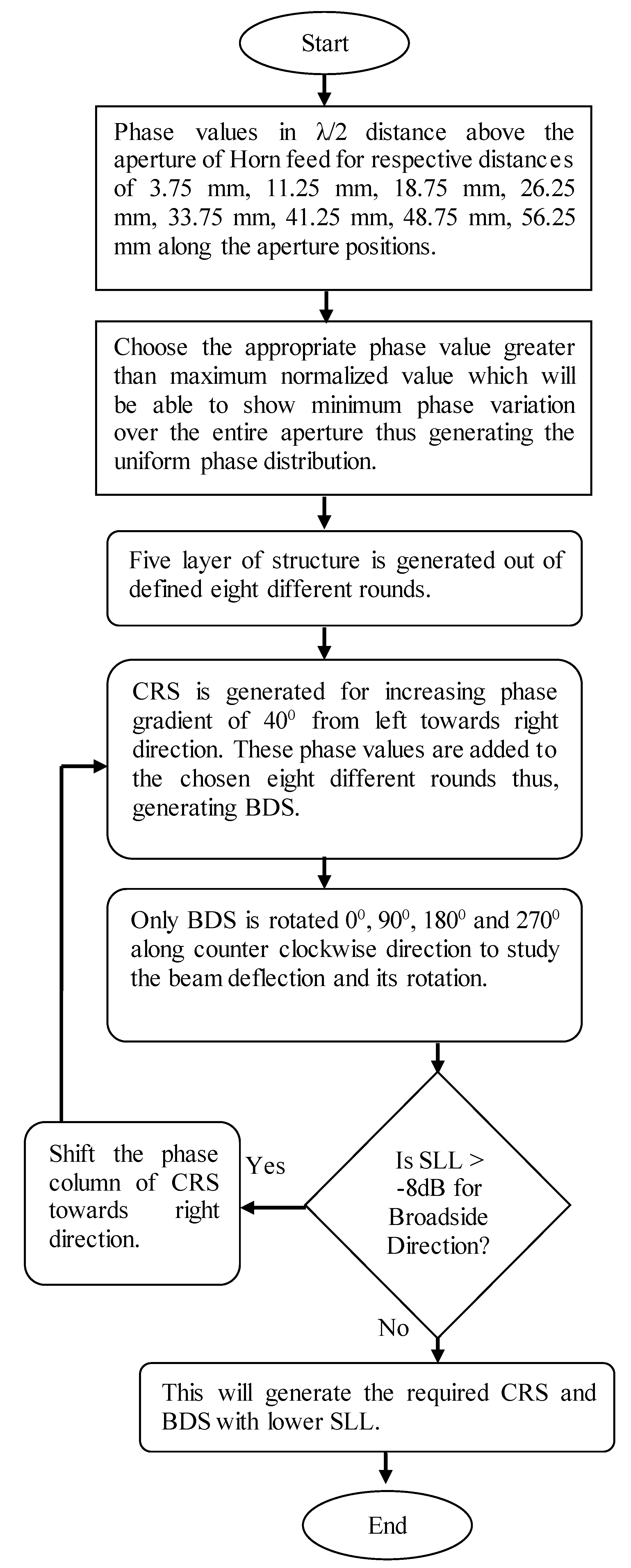
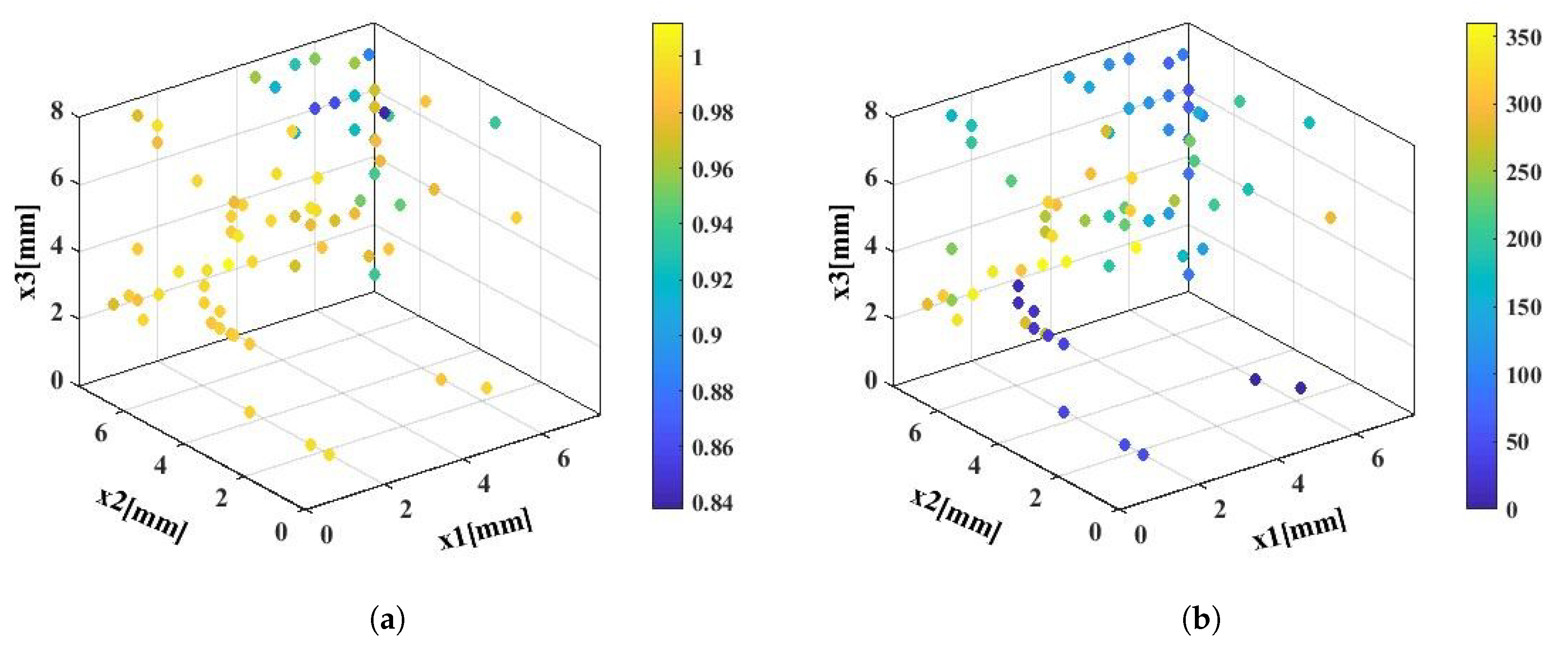
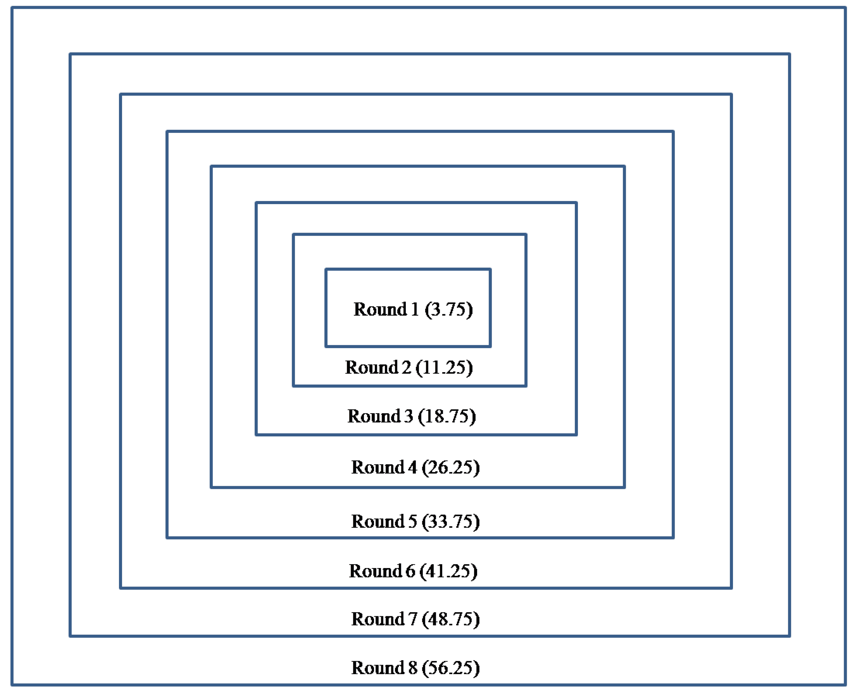
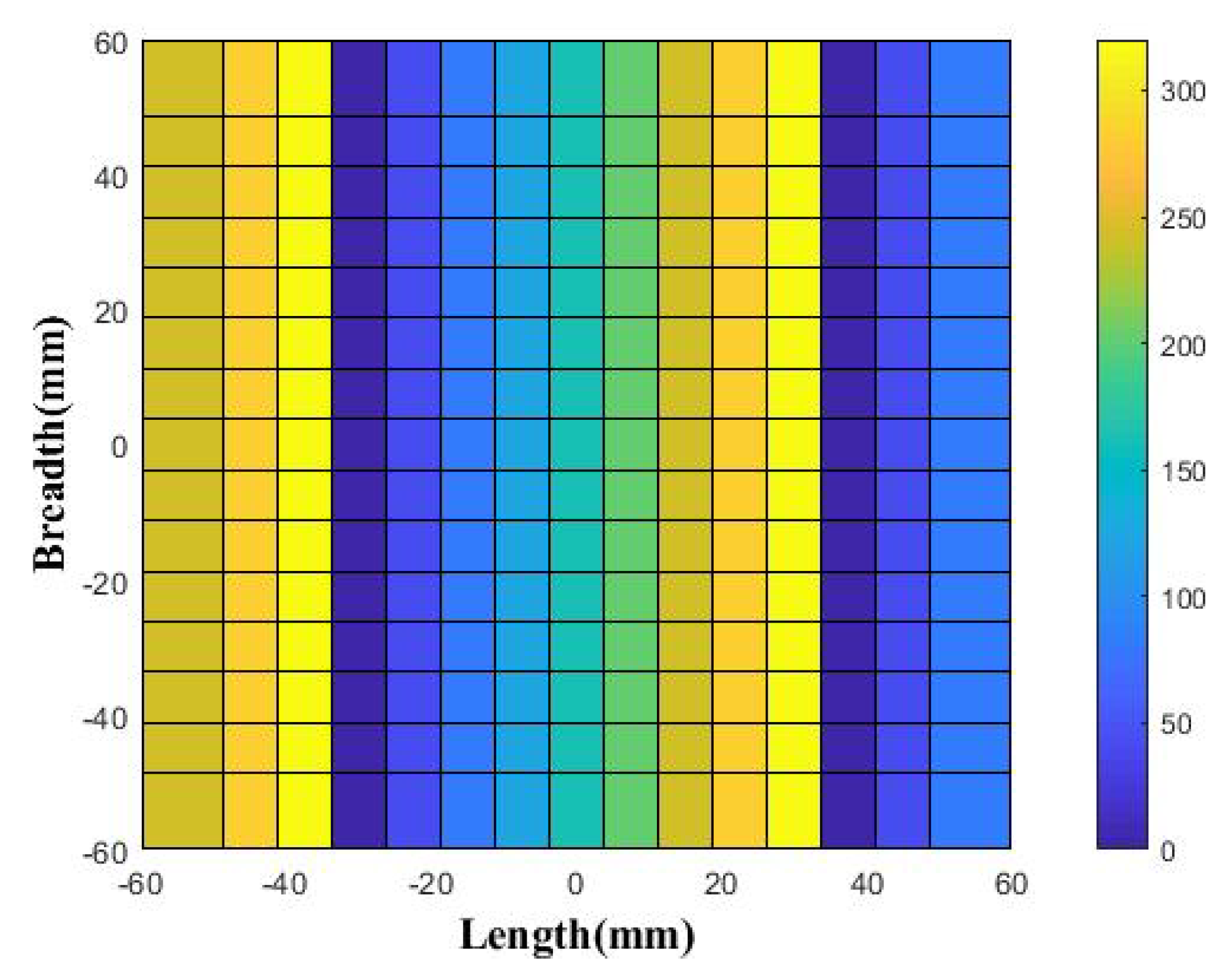
To verify the concept of deflection of the beam through 3D printed surfaces, we have chosen four layers of cubes that are held by three perpendicular cylindrical rods that are stacked one after another, as shown in Figure 1. The cubes present along each layer are x2, x1, x2, x3 from top Port 2 to bottom Port 1, as depicted in Figure 1a for a four-layer arrangement of cubes, whereas for a five-layer cube arrangement, as shown in Figure 1b, we have x1, x2, x3, x2, x1, whose relative size varies from a minimum of 0.5 mm (0.02 λ ) to a maximum of 7.5 mm (0.3 λ ). The x1, x2 and x3 represents relative size of cubes. The distance between the ports to the top surface of the cylindrical rod is h, the transmission coefficient is denoted by τ and the reflection coefficient by . In the horizontal plane, we have x1 and x2, whereas in the vertical plane, we have x3. It is noted from Figure 2 and Figure 3 that for the smaller sizes of cubes, we have higher transmission magnitude values, whereas the larger cubes size show higher phase values. These unit cells are operating at the design frequency of 12 GHz ( λ = 25 mm). The relative size of cylindrical rods along with cube size is detailed in [31]. The maximum length of three perpendicular cylindrical rods is 7.5 mm, which holds the respective cubes. Variation in cube size from 0.5 to 7.5 mm 3 in intervals of 0.5 mm 3 is able to show the transmission coefficient magnitude and phase values. The four and five layers of cube arrangement have generated magnitude and phase plots in degrees, as shown in Figure 2a,b and Figure 3a,b, respectively. The cube dimensions are shown by x1, x2 and x3. The database of the transmission coefficient magnitude and phase in degree is generated through the specific arrangement of these cube distributions for four- and five-layer configurations. The respective cube dimensions are shown along the x-axis, y-axis and z-axis, as depicted in Figure 2 and Figure 3.
The transmission magnitude highlights the fact that its value is closer to unity for relatively smaller cube sizes, as noted from Figure 2a, and interestingly, transmission phase plots depict that a higher phase value of above 300 is obtainable for relatively higher cube sizes, as shown in Figure 2b. Interestingly, for the five-layer cube arrangement, we have found that the transmission magnitude tends to be closer to unity for smaller cube sizes, as noted in Figure 3a, and the successive transmission phase is higher than 300 , which is highlighted in Figure 3b. Thus, we have created the database for both transmission magnitude and phase values for five- and four-layer cubes, which act as building blocks for the generation of BDS that is described in a later section of this article.
The unit cell is analyzed in a two-port network to generate the required database of transmission coefficient magnitude and phase values, which are used to design the proposed BDS prototype, and is excited by a feed horn. The field propagates throughout all the layers of arranged cubes and is radiated in free space. The field phase across the radiating surface can be controlled by electronically tuning the characteristics of the individual cells to achieve beam tilting [34]. The tilting direction ( θ ) can be calculated by Equation (1) [35],
θ = arcsin λ γ d 2 π
where λ is the wavelength of the operating frequency, γ is the phase difference assumed between the adjacent radiating unit cells, and d is the separation distance between those radiating elements. This Equation (1) can be rewritten to derive the phase difference values, as shown in Equation (2).
γ = ω d sin θ c
where c is the velocity of the electromagnetic wave, and ω is angular frequency. This shows that there is a time delay, τ , between the adjacent radiating elements, which is represented as in Equation (3).
τ = d γ d ω = d sin θ c
Equation (3) shows that the beam direction angle can be achieved through tuning the value of τ . In this case, the phase gradient is 40 as considered in the generation of CRS, which is eventually used to design BDS, as discussed in a later section.
The study of tilting behavior begins with the step to make more of a planar wavefront above the feed horn source. The phase distribution obtained above the horn fed at λ /2 distance is mentioned in [31], whereby noting these relative phase values, we have started to maintain the five-layer cube distribution for eight different rounds from the center towards the aperture end, moving from a distance of 3.75 mm from the center of aperture to 56.25 mm towards the end of aperture. Round 1, Round 2, Round 3, Round 4, Round 5, Round 6, Round 7 and Round 8 signify the respective distances of 3.75, 11.25, 18.75, 26.25, 33.75, 41.25, 48.75, 56.25 mm along the aperture distribution. Rounds are the defined aperture positions from the center of the structure. These respective rounds are shown in Figure 4, where the center position is of Round 1 with a radial distance of 3.75 mm from the center of the structure. These rounds are maintained for radial distances of 11.25, 18.75, 26.25, 33.75, 41.25, 48.75 and 56.25 mm as noted from the center of the structure and are indicated by respective rounds (i.e., Round 2, Round 3, Round 4, Round 5, Round 6 and Round 7). Thus, this will arrange the respective cubes in defined apertures of 16 λ × 16 λ .
This will make the overall phase distribution more uniform, which will be used to generate the BDS, as detailed by the synthesis algorithm and flow chart. The synthesis algorithm is detailed below:
  • Step 1: Note the phase values at λ /2 distance above the aperture of Horn fed for respective distances of 3.75, 11.25, 18.75, 26.25, 33.75, 41.25, 48.75, 56.25 mm along the aperture positions.
  • Step 2: Normalize the noted phase values and choose the values greater than the maximum phase value. The chosen maximum values run through a complete 360 phase cycle.
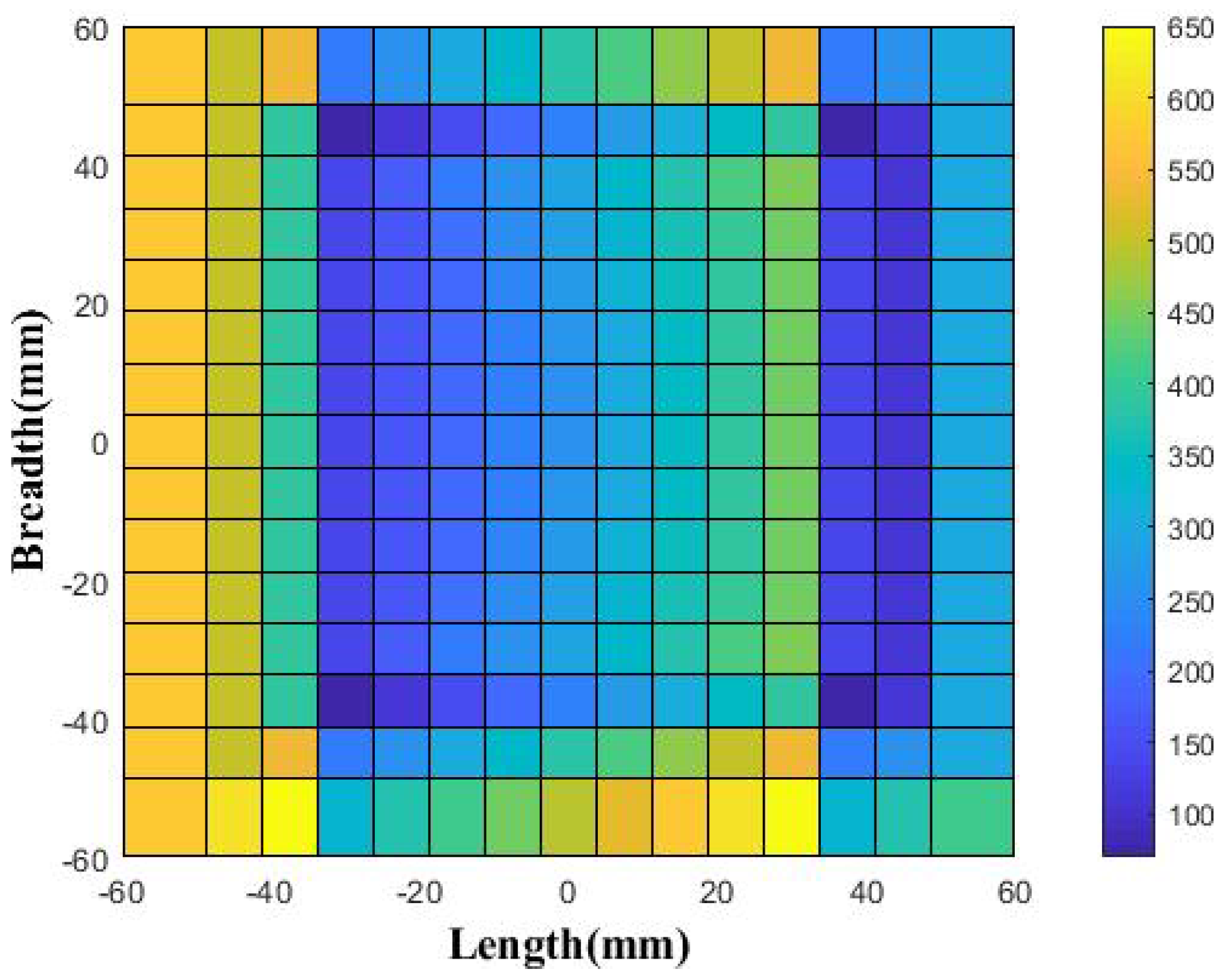
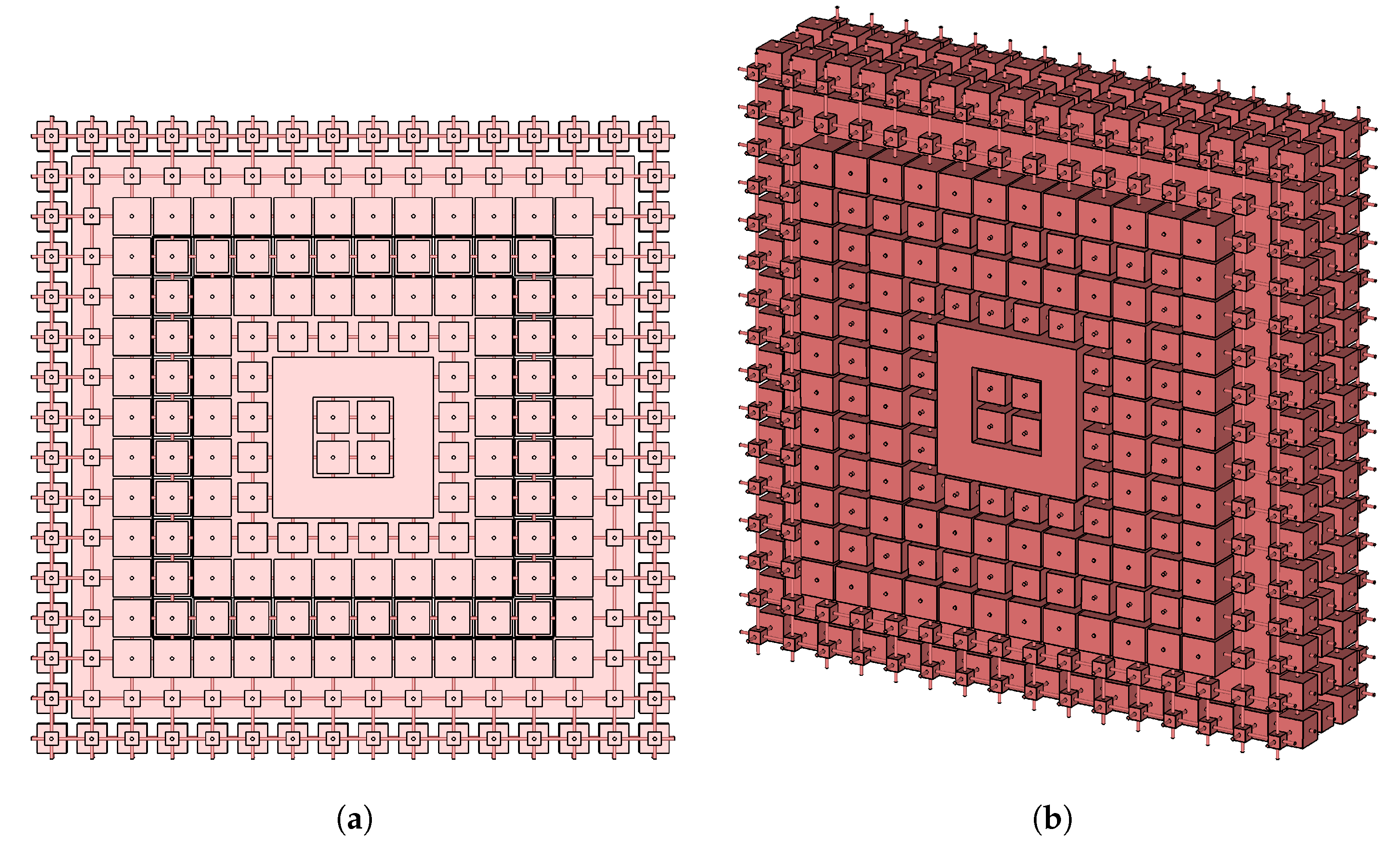
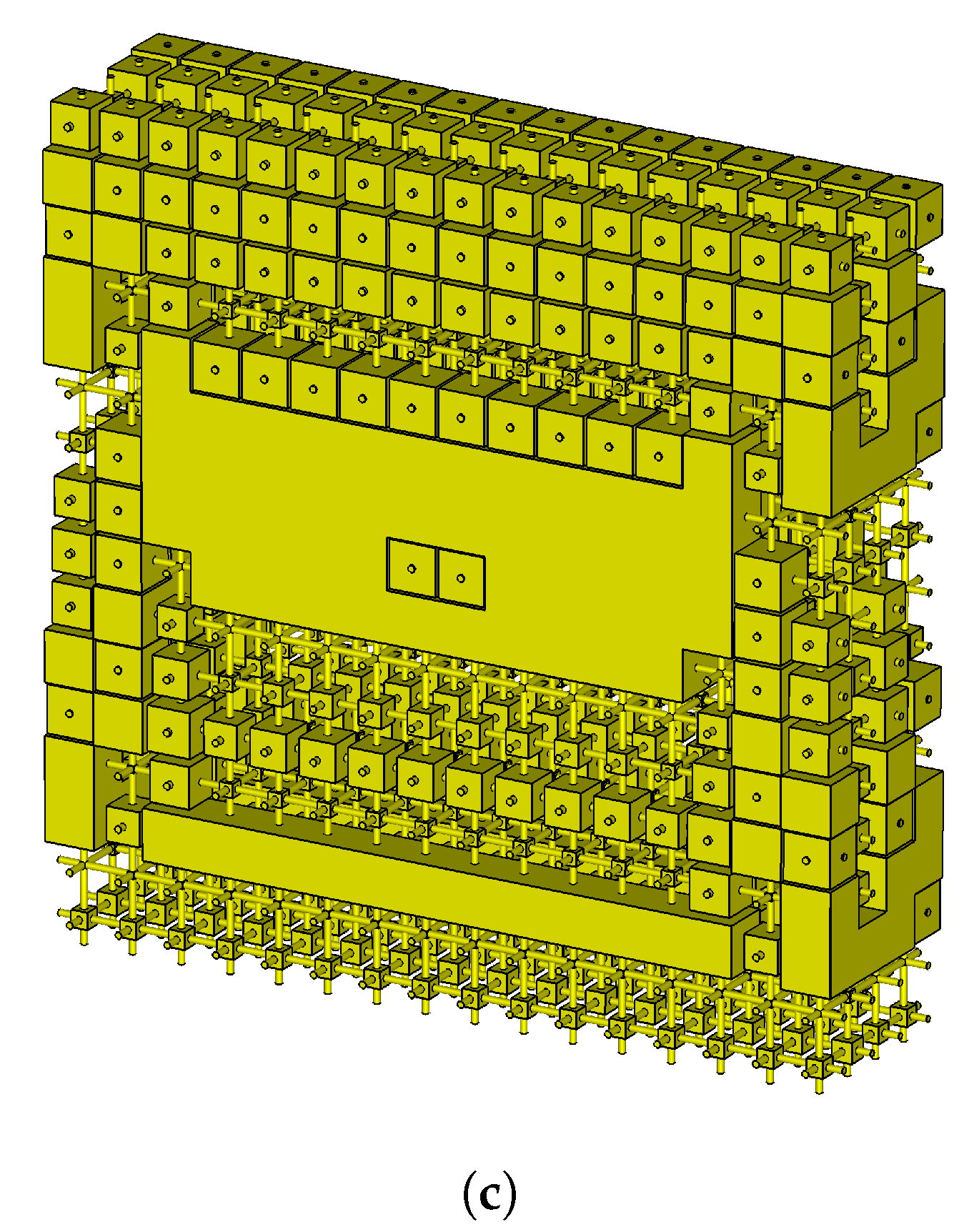
  • Step 3: Generate the five-layer structure of the proposed cubes with eight different rounds that will be able to decrease the overall phase variation along the defined aperture of 16 λ × 16 λ . Thus, appropriate cubes sizes are selected for defined aperture positions by giving the command from Matlab, which is interlinked with Computer Simulation Technology (CST) software.
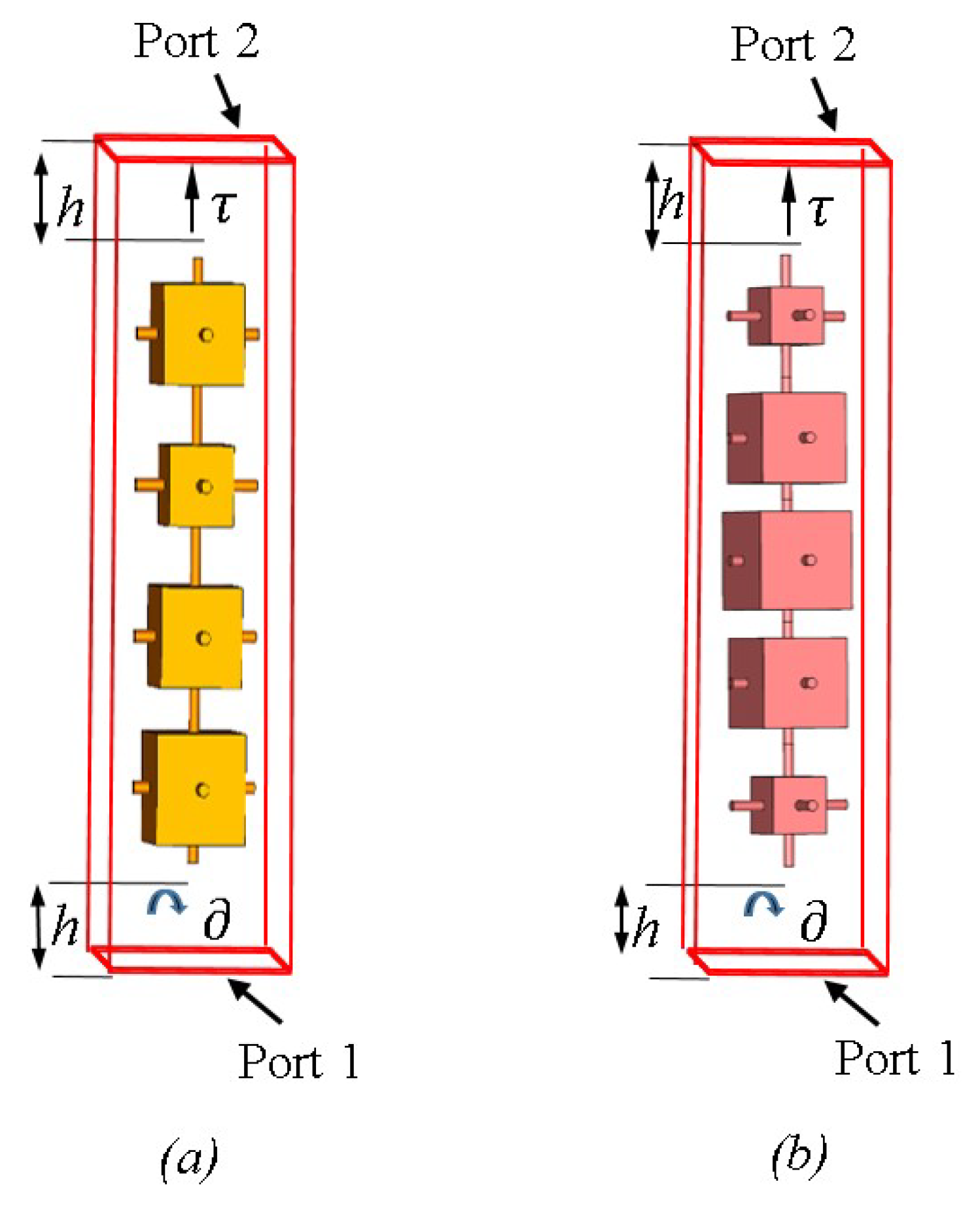
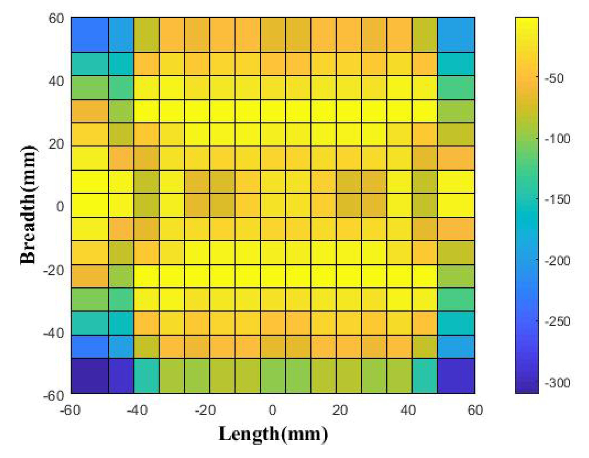
  • Step 4: Conical Rotating Surface (CRS) is generated for an increasing phase gradient of 40 from the left towards the right direction. These phase values are added to the phase of the eight chosen different rounds from Step 3, which will design the BDS. These surfaces are placed along the E-plane of the feed horn source.
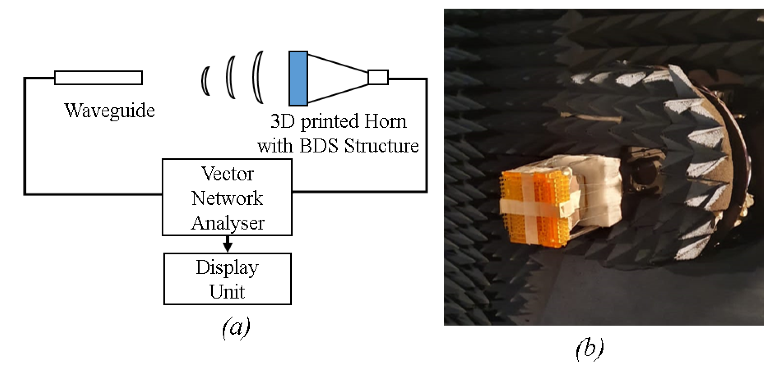
  • Step 5: In order to study the beam deflection, BDS is placed above the feed horn source and the angle of rotation is noted for 0 , 90 , 180 and 270 in the counterclockwise direction.
  • Step 6: CRS is rotated 180 in the anticlockwise direction and placed 1 mm above the BDS, which is kept just above the horn aperture. Hence, the broadside directivity and gain are noted along with the side lobe level (SLL) at the design frequency.
  • Step 7: Check for SLL whether it is higher than −8 dB. If it is higher, then shift the phase column towards the right direction, which will generate new phase values for CRS and consequently for BDS. Repeat Step 5 until a lower side lobe level of −8 dB is obtained.
  • Step 8: Hence, the CRS and BDS are selected that will be able to show a lower side lobe level for broadside conditions where the phase gradient of both surfaces are aligned opposite to each other.
The steps highlighted in the synthesis algorithm are shown in a flowchart in Figure 5.

3. Phase Plots for the Generation of CRS and BDS

As described in the above section, the step starts with the generation of a BDS surface whereby a more uniform phase is required above the horn aperture. In order to maintain a uniform phase, we have chosen a suitable value above the maximum normalized phase value for the feed horn only condition through multiple simulation runs from the CST software. The five-layer database was used to maintain uniformity in the phase distribution. Here, the respective phase value towards the end of aperture positions particularly for 41.25, 48.75 and 56.25 mm are fine tuned in order to achieve more uniformity in the overall phase variation. Thus, the phase values in degree arranged across the aperture are shown in Figure 6, where the minimum and maximum values of 70 and 330 are noted, respectively. Additionally, the obtained phase variation in degree at 6.25 mm ( λ /4) above the top surface of the designed five-layer prototype is shown in Figure 7. Here, it is observed that the phase values become more uniform towards the center position and are mostly below 30 , and slightly higher values are seen towards the end of aperture and are relatively greater than 200 . Additionally, the obtained five layer’s pictorial outlooks with its top and perspective views are depicted in Figure 8a,b, respectively. Since the cubes that are placed in the top and bottom of the five-layer prototype are the same, we have mentioned only the top view.
In the next step, we have designed the CRS with a phase increment of 40 from the left of the aperture toward the right side. In each column of the phase distribution, the phase values will be the same, and it will be incremented as we move towards the next column. These phase values in degrees are highlighted in Figure 9. The minimum phase value of 0 and the maximum phase value of 320 are thus maintained. The 0 phase is kept in the fourth column starting from the left side and this 0 phase column is shifted right for each column, i.e., fifth, sixth, etc., to the sixteenth column and again shifting back to the first column, which is performed so as to obtain minimum side lobe level for the broadside condition. The increasing phase gradient is maintained from the bottom towards the upper side, which is along the E-plane.
The phase distribution as noted in Figure 6 is added to the phase shown in Figure 9, so the combined phase in degrees is obtained, as shown in Figure 10, which will generate the BDS surface and be able to deflect the beam to a particular elevation angle. This four-layer cube arrangement is able to show the minimum side lobe level in combination with CRS for broadside direction. Since, the cubes defined for each layer of this four-layer BDS structure are not symmetrical, we have interlinked CST software with Matlab so that the systematically generated code is run for the proper placement of these cubes. The top, bottom and perspective views are shown in Figure 11a–c, respectively. The relative dimensions in terms of footprint and height of the fabricated BDS prototype, as shown in Figure 11, are of 120 × 120 mm and 30 mm, respectively. There are 16 cylindrical rods across the proposed BDS that holds the cubes whose size varies from a minimum of 0.5 mm 3 to a maximum of 7.5 mm 3 and are arranged in defined aperture positions that vary from 3.75 mm from the center of aperture to 56.25 mm towards the edge of the BDS aperture, with variable sizes for three different layers that accommodate cube sizes of x3, x2 and x1, where the top layer of BDS mimics the cubes of middle x2 values. Since each cylindrical layer height is 7.5 mm and the proposed BDS consists of four layers, the overall height of BDS is 30 mm. Before picking this arrangement of cube values, we ran several different BDS prototypes, generated after shifting the 0 phase column simultaneously to the right.
Similarly, the electric field pattern is depicted with the use of the BDS prototype above the feed horn, as shown in Figure 12, which shows that the beam is tilted with some fixed elevation angle.

4. Results and Discussion

This section details the fabrication of the proposed BDS prototype and the obtained radiation beam patterns along with the VSWR results. The requirement of a full 360 phase is addressed through the required four-layer cube arrangement. It is noted that the smaller cube sizes generate higher transmission magnitude values, which are close to 0.99, whereas the larger cubes sizes show greater phase values. Interestingly, the side lobe levels are less than −5 dB and the VSWR is less than 2 over the frequency range of interest.

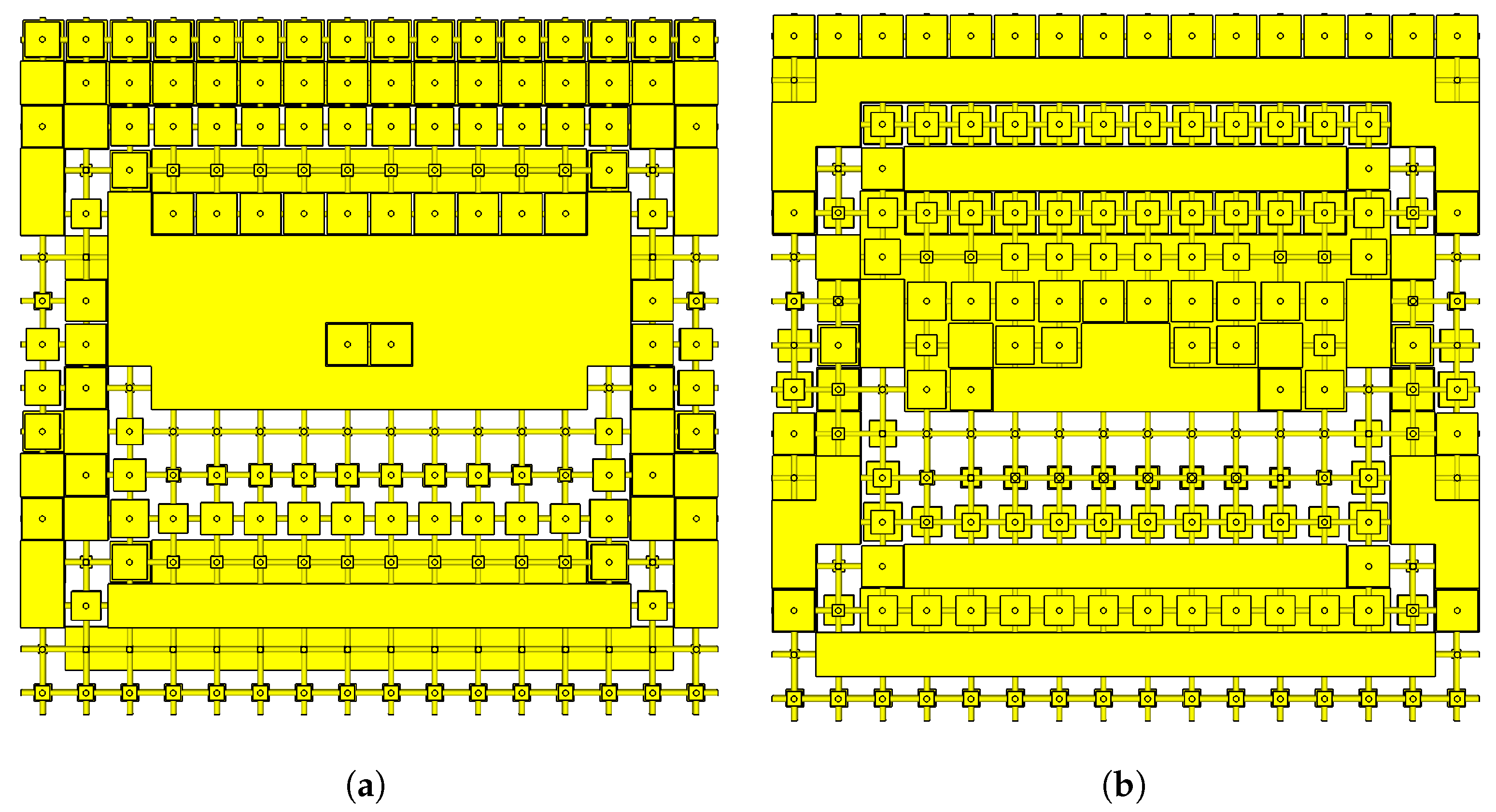
4.1. Fabrication of BDS Prototypes

The multijet 3D printing method is adopted for realizing the proposed BDS surface where the Stratasys J750 3D printer was used, which is able to produce the part in a single print. It operates with Multijet Printing (MJP) method, which is a material jetting printing process that utilizes piezo print head technology to deposit materials layer-by-layer. These high-resolution 3D printers use separate, meltable or dissolvable support materials that can be completely removed in a virtually hands-free process, allowing even the most delicate and complex features to be thoroughly cleaned without damage. The MJP print head prints layers of UV curable liquid plastic onto a flat platform. Wax support material is also jetted to fill voids and other non-freestanding features. A UV lamp flashes to solidify material creating a fully cured plastic part and to crosslink a photopolymer. A printer head jets tiny droplets of photopolymers in the shape of the first layer. The UV lamp attached to the printer head crosslinks the polymer and locks the shape of the layer in place. In the MJP process, thousands of layers are built upon one another to create solid parts. Via hundreds of tiny jets, the MJP printer dispenses a photopolymer over a specific area. The print head then cures (solidifies) the photopolymer via a UV light. After a layer has been deposited and cured, the build platform drops down one layer thickness, and the process is repeated to build up a 3D part. This printer is capable of printing highly complex and high-resolution parts with fine features. The operation deposits the build material in a rapid and line wise fashion. Because of this, MJP printers are able to print multiple parts in a single line with no effect on build speed.
A material having permittivity ( ϵ r ) of 2.8 and loss tangent (tan δ ) of 0.124 was used to 3D print the BDS prototype, whereas Acrylonitrile Butadiene Styrene (ABS) is used to fabricate the horn with 100% infill value and is used as a feed source underneath the BDS [31]. There is no gap between BDS and the aperture of the 3D printed horn used as a feed source, which decreases the overall height of the proposed structure. The VSWR measurements are performed using the Agilent PNA-X Network Analyzer, whereas the radiation measurements are performed in the NSI-700S-50 spherical near-field measurement system at the Australian Antenna Measurement Facility. The experimental setup is shown in Figure 13a,b, respectively, where on the left side, a block diagram of the experimental setup is depicted, and on the right side, fabricated BDS over the 3D printed feed horn is shown in the testing environment.

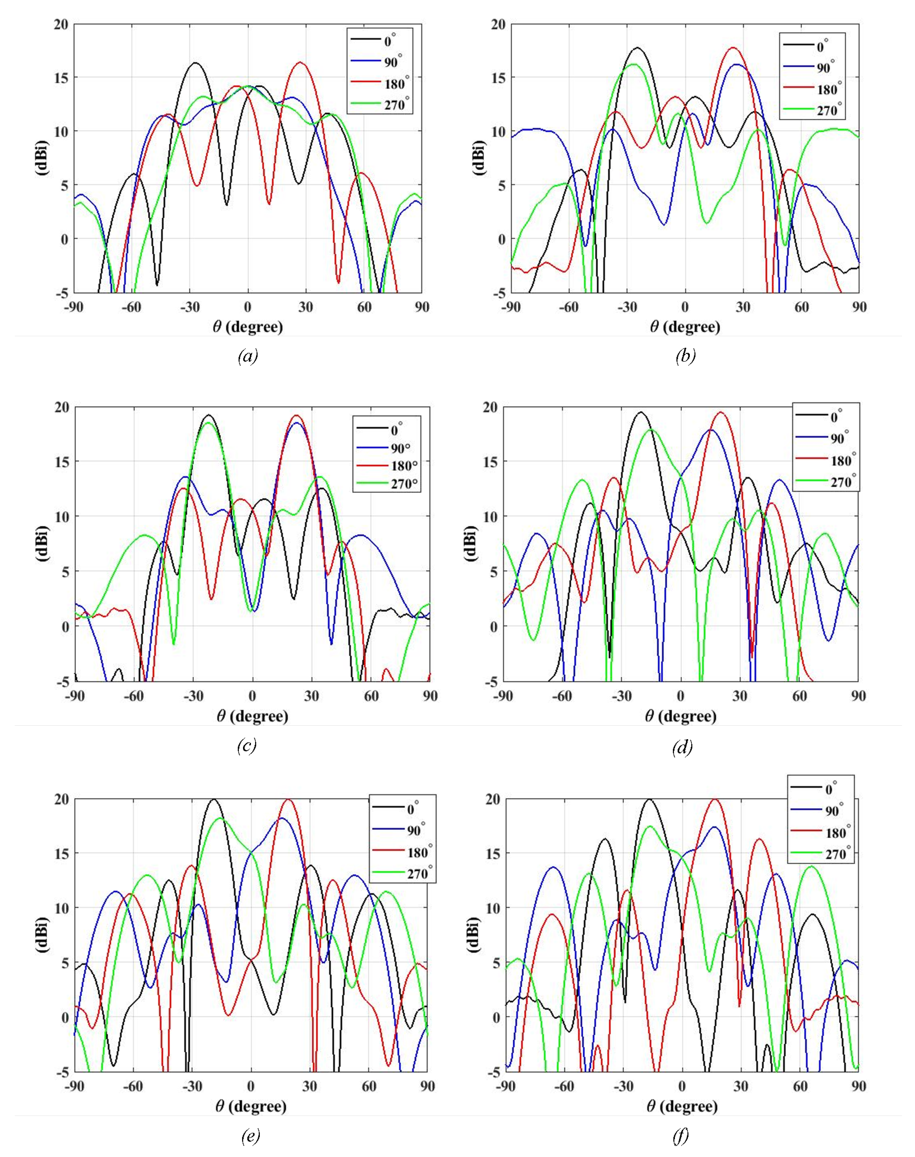
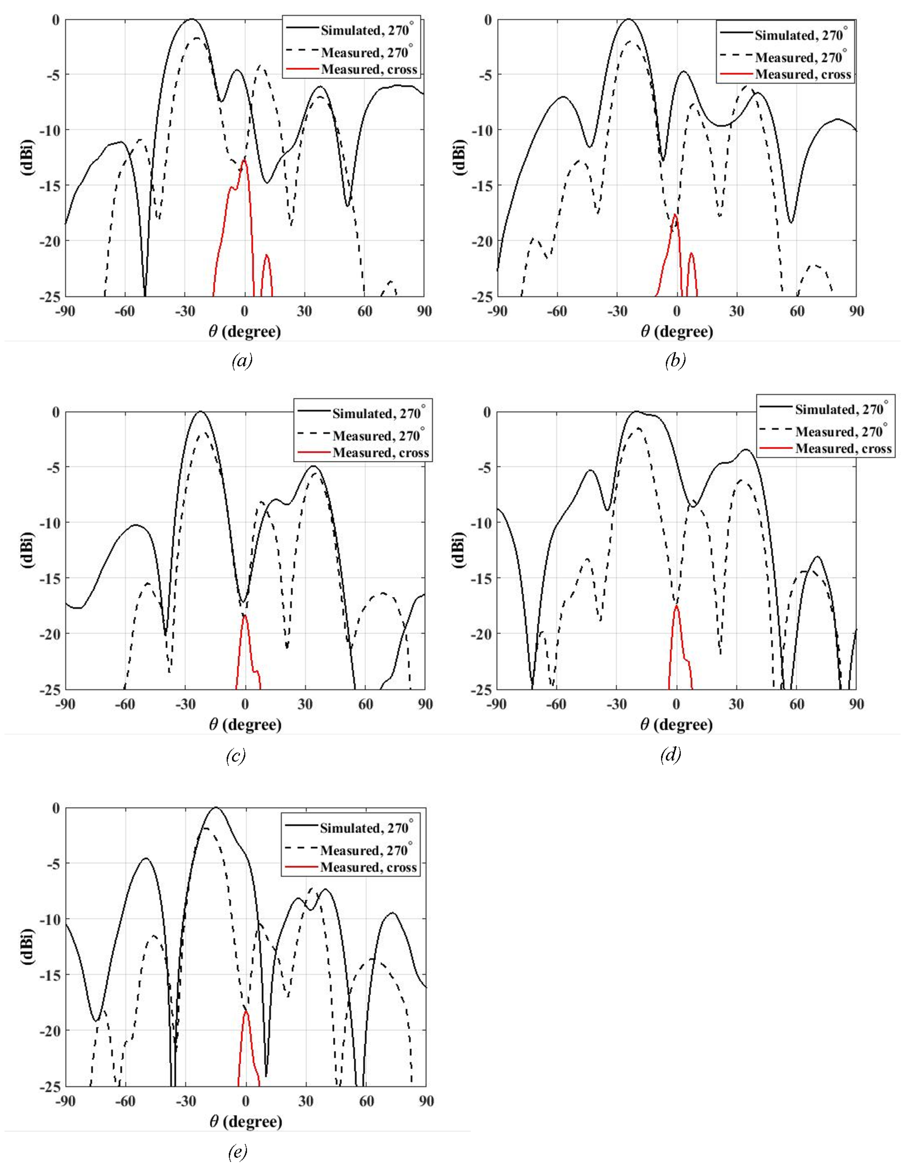
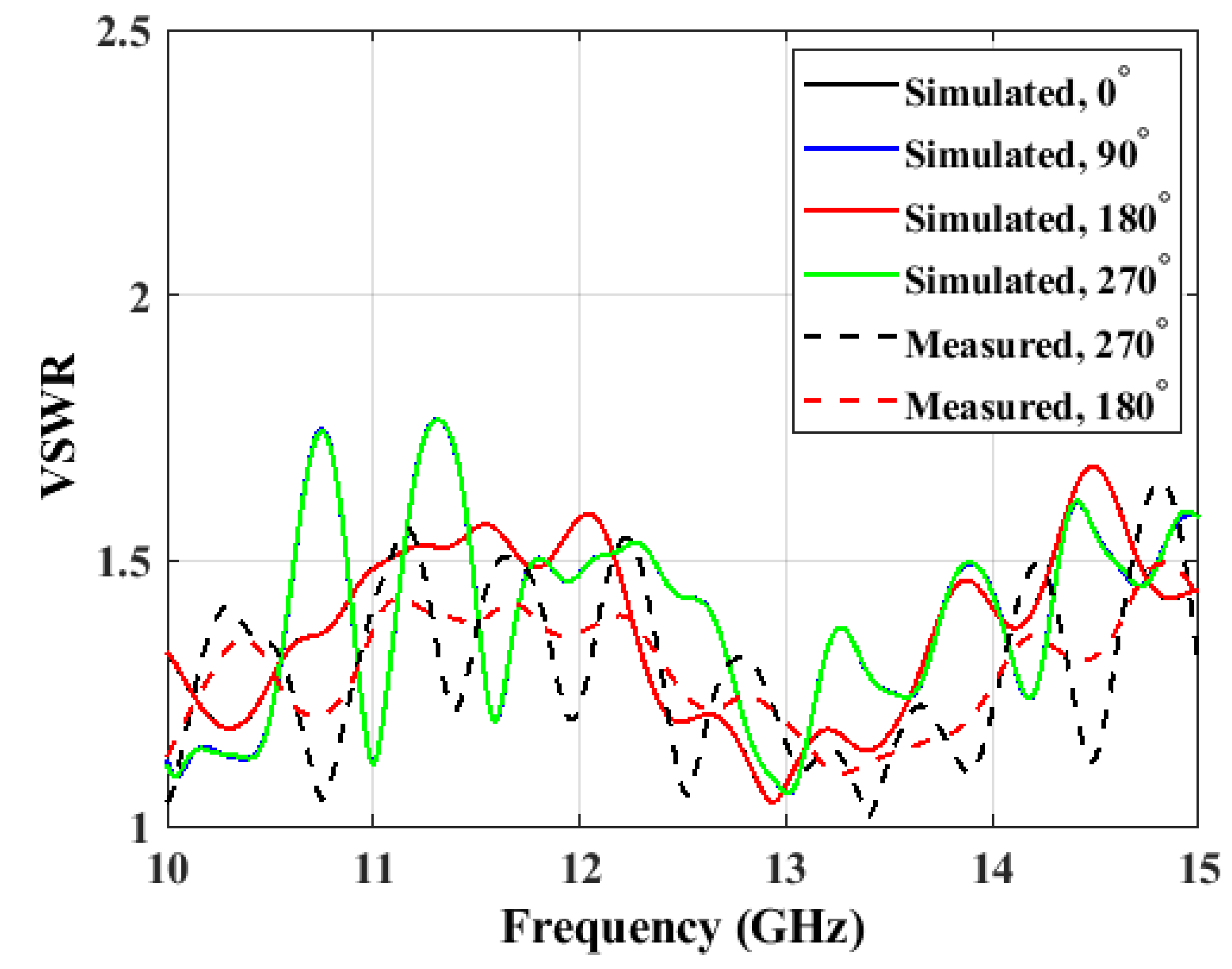
4.2. Radiated Beam Patterns with BDS Surface

The defined four-layer BDS structure is able to deviate the beam to the fixed elevation angle ( θ ) where as its counter rotation shows the different azimuth angle ( ϕ ). We have considered four different orientation angles as of 0 , 90 , 180 , and 270 rotated counter-clockwise direction where the respective peak radiation patterns deviate, as shown in Figure 14a–f for 10, 11, 12, 13, 14 and 15 GHz, respectively. Firstly, the orientation of 0 indicates the placement of BDS along the E-plane where the phase gradient increases from bottom to top. Afterward, this BDS surface is counter-rotated in steps of 90 so that we will have another three orientations that will indicate 90 , 180 , and 270 positions. As noted in Figure 14a–f, the beam direction is opposite for 0 and 180 orientations, and similar opposite patterns are observed for 90 and 270 orientations.
In order to verify our design concept for BDS beam deviation, we have chosen the 270 orientation and have compared the measured results, as shown in Figure 15a–e, respectively, for frequencies of 11, 11.5, 12, 12.5 and 13 GHz. In the 270 orientation of BDS, the main lobe values obtained for 11, 11.5, 12, 12.5 and 13 GHz are respectively 16.2, 16.7, 18.5, 16.4 and 17.9 dBi, respectively, where the main lobe directions are in 27 , 24 , 22 , 20 and 15 in which the negative sign indicates the beam direction in the opposite direction. Similarly, the side lobe levels as noted for 11, 11.5, 12, 12.5 and 13 GHz are, respectively, −4.6, −4.7, −4.9, −3.4 and −4.5 dBi. The measured peak value is slightly deviated from the simulated values for 11, 11.5, 12, 12.5 and 13 GHz frequencies because of error in alignment of the BDS surface during measurement steps. However, the figures as depicted from Figure 15a–e show the similarity obtained for the deviation of beam as compared against the simulated patterns.
Similarly, we have plotted the voltage standing wave ratio (VSWR), as shown in Figure 16, where it shows the wideband nature of the proposed BDS prototype with values less than two through the operating frequency range. The measured VSWR condition for the 270 orientation case is also shown, which depicts the matching of the proposed BDS prototype.
Table 1 presents the performance comparison of the proposed beam tilting prototype with existing state-of-the-art work presented in the literature. It shows that the wideband tilting feature lies within the Ku-band operation covering from 10 to 15 GHz. There is no relative gap between the BDS prototype and feed horn, which eventually decreases the overall height of the designed antenna system. The peak gain is maintained for around 18.5 dBi and is comparatively smaller in aperture dimension.

5. Conclusions

In this paper, we have presented three-dimensional printed antenna prototypes for beam tilting at frequencies from 10 to 15 GHz. The geometrical complexity of the 3D printed structures is easier to be realized. The BDS prototype is able to show the elevation degree of 22 . 5 and could rotate the beam along with its rotation in a counter-clockwise direction. The four-layer cube arrangement is able to address the need for full phase values, which is applied to have the beam tilting phenomenon. The radiation patterns are consistent across the frequency range of interest, and the side lobe levels are less than −5 dB. The voltage standing wave ratio of the designed prototype shows the value is less than 2 and it is well-matched within the operating frequency band. The research could be further carried out by proposing a structure that could show a conical rotation of the tilted beam. The electric motor could be used to demonstrate the automatic rotation of the BDS prototype, where the system can be operated remotely. The radiation patterns of the analytically designed antenna are numerically simulated using the CST microwave studio, which demonstrates broad bandwidth in the operating frequency band, covering the Ku-band, and are in good agreement with measured radiation patterns.

Author Contributions

S.S., H.Z., S.M.A., A.K., B.M. and M.A. equally contributed to the methodology, performance analysis and manuscript draft. All authors have read and agreed to the published version of the manuscript.

Funding

This work was supported in part by the Australian Research Council (ARC) and in part by the Macquarie University International Research Excellence Scholarship (iMQRES).

Acknowledgments

We want to extend thankfulness to CSIRO, Marsfield, NSW, Australia, and Macquarie University for providing support for measurements of the antenna prototype.

Conflicts of Interest

The authors declare no conflict of interest.

References

  1. Gu, Y.; Lo, A.; Niemegeers, I. A survey of indoor positioning systems for wireless personal networks. IEEE Commun. Surv. Tutor. 2009, 11, 13–32. [Google Scholar] [CrossRef] [Green Version]
  2. Fu, X.; Yang, F.; Liu, C.; Wu, X.; Cui, T.J. Terahertz Beam Steering Technologies: From Phased Arrays to Field-Programmable Metasurfaces. Adv. Opt. Mater. 2020, 8, 1900628. [Google Scholar] [CrossRef]
  3. Ozpinar, H.; Aksimsek, S.; Tokan, N.T. A novel compact, broadband, high gain millimeter-wave antenna for 5G beam steering applications. IEEE Trans. Veh. Technol. 2020, 69, 2389–2397. [Google Scholar] [CrossRef]
  4. Han, L.; Cheng, G.; Han, G.; Ma, R.; Zhang, W. Electronically beam-steering antenna with active frequency-selective surface. IEEE Antennas Wirel. Propag. Lett. 2018, 18, 108–112. [Google Scholar] [CrossRef]
  5. Akbari, M.; Farahani, M.; Ghayekhloo, A.; Zarbakhsh, S.; Sebak, A.R.; Denidni, T.A. Beam Tilting Approaches Based on Phase Gradient Surface for mmWave Antennas. IEEE Trans. Antennas Propag. 2020, 68, 4372–4385. [Google Scholar] [CrossRef]
  6. Balanis, C.A. Antenna Theory: Analysis and Design; John Wiley & Sons: Hoboken, NJ, USA, 2016. [Google Scholar]
  7. Uchendu, I.; Kelly, J.R. Survey of beam steering techniques available for millimeter wave applications. Prog. Electromagn. Res. 2016, 68, 35–54. [Google Scholar] [CrossRef] [Green Version]
  8. Ma, H.F.; Cui, T.J. Three-dimensional broadband and broad-angle transformation-optics lens. Nat. Commun. 2010, 1, 1–7. [Google Scholar]
  9. Yi, J.; Burokur, S.N.; de Lustrac, A. Experimental validation of a transformation optics based lens for beam steering. Appl. Phys. Lett. 2015, 107, 154101. [Google Scholar] [CrossRef]
  10. Foster, R.; Nagarkoti, D.; Gao, J.; Vial, B.; Nicholls, F.; Spooner, C.; Haq, S.; Hao, Y. Beam-steering performance of flat Luneburg lens at 60 GHz for future wireless communications. Int. J. Antennas Propag. 2017, 2017, 7932434. [Google Scholar] [CrossRef] [Green Version]
  11. Jia, D.; He, Y.; Ding, N.; Zhou, J.; Du, B.; Zhang, W. Beam-steering flat lens antenna based on multilayer gradient index metamaterials. IEEE Antennas Wirel. Propag. Lett. 2018, 17, 1510–1514. [Google Scholar] [CrossRef]
  12. Mateo-Segura, C.; Dyke, A.; Dyke, H.; Haq, S.; Hao, Y. Flat Luneburg lens via transformation optics for directive antenna applications. IEEE Trans. Antennas Propag. 2014, 62, 1945–1953. [Google Scholar] [CrossRef]
  13. Nicholls, J.G.; Hum, S.V. Full-space electronic beam-steering transmitarray with integrated leaky-wave feed. IEEE Trans. Antennas Propag. 2016, 64, 3410–3422. [Google Scholar] [CrossRef]
  14. Vilenskiy, A.R.; Makurin, M.N.; Lee, C.; Ivashina, M.V. Reconfigurable Transmitarray With Near-Field Coupling to Gap Waveguide Array Antenna for Efficient 2-D Beam Steering. IEEE Trans. Antennas Propag. 2020, 68, 7854–7865. [Google Scholar] [CrossRef]
  15. Massaccesi, A.; Dassano, G.; Pirinoli, P. Beam scanning capabilities of a 3d-printed perforated dielectric transmitarray. Electronics 2019, 8, 379. [Google Scholar] [CrossRef] [Green Version]
  16. Abbasi, M.I.; Dahri, M.H.; Jamaluddin, M.H.; Seman, N.; Kamarudin, M.R.; Sulaiman, N.H. Millimeter wave beam steering reflectarray antenna based on mechanical rotation of array. IEEE Access 2019, 7, 145685–145691. [Google Scholar] [CrossRef]
  17. Nayeri, P.; Liang, M.; Sabory-Garcı, R.A.; Tuo, M.; Yang, F.; Gehm, M.; Xin, H.; Elsherbeni, A.Z. 3D printed dielectric reflectarrays: Low-cost high-gain antennas at sub-millimeter waves. IEEE Trans. Antennas Propag. 2014, 62, 2000–2008. [Google Scholar] [CrossRef]
  18. Da Wu, M.; Li, B.; Zhou, Y.; Liu, Y.; Wei, F.; Lv, X. Design and measurement of a 220 GHz wideband 3-D printed dielectric reflectarray. IEEE Antennas Wirel. Propag. Lett. 2018, 17, 2094–2098. [Google Scholar]
  19. Katare, K.K.; Chandravanshi, S.; Biswas, A.; Akhtar, M.J. A compact configuration of semicircular metasurface loaded slot antenna for beam steering application. Int. J. RF Microw. Comput. Aided Eng. 2019, 29, e21526. [Google Scholar] [CrossRef]
  20. Naqvi, A.H.; Lim, S. A beam-steering antenna with a fluidically programmable metasurface. IEEE Trans. Antennas Propag. 2019, 67, 3704–3711. [Google Scholar] [CrossRef]
  21. Bazaz, S.R.; Rouhi, O.; Raoufi, M.A.; Ejeian, F.; Asadnia, M.; Jin, D.; Warkiani, M.E. 3D printing of inertial microfluidic devices. Sci. Rep. 2020, 10, 1–14. [Google Scholar]
  22. Bazaz, S.R.; Mehrizi, A.A.; Ghorbani, S.; Vasilescu, S.; Asadnia, M.; Warkiani, M.E. A hybrid micromixer with planar mixing units. RSC Adv. 2018, 8, 33103–33120. [Google Scholar] [CrossRef] [Green Version]
  23. Cairone, F.; Gagliano, S.; Carbone, D.C.; Recca, G.; Bucolo, M. Micro-optofluidic switch realized by 3D printing technology. Microfluid. Nanofluid. 2016, 20, 61. [Google Scholar] [CrossRef]
  24. Afzal, M.U.; Matekovits, L.; Esselle, K.P.; Lalbakhsh, A. Beam-Scanning Antenna Based on Near-Electric Field Phase Transformation and Refraction of Electromagnetic Wave Through Dielectric Structures. IEEE Access 2020, 8, 199242–199253. [Google Scholar] [CrossRef]
  25. Afzal, M.U.; Esselle, K.P. Steering the beam of medium-to-high gain antennas using near-field phase transformation. IEEE Trans. Antennas Propag. 2017, 65, 1680–1690. [Google Scholar] [CrossRef]
  26. Baba, A.A.; Hashmi, R.M.; Esselle, K.P.; Attygalle, M.; Borg, D. A millimeter-wave antenna system for wideband 2-D beam steering. IEEE Trans. Antennas Propag. 2020, 68, 3453–3464. [Google Scholar] [CrossRef]
  27. Zhao, X.; Yuan, C.; Liu, L.; Peng, S.; Zhang, Q.; Yu, L.; Sun, Y. All-metal beam steering lens antenna for high power microwave applications. IEEE Trans. Antennas Propag. 2017, 65, 7340–7344. [Google Scholar] [CrossRef]
  28. Han, J.; Li, L.; Zhang, T.; Xi, R. Control and improvement of antenna gain by using multilayer non-uniform metasurfaces. EPJ Appl. Metamater. 2019, 6, 4. [Google Scholar] [CrossRef]
  29. Shrestha, S.; Zahra, H.; Abbasi, M.A.B.; Asadnia, M.; Abbas, S.M. Increasing the directivity of resonant cavity antennas with nearfield transformation meta-structure realized with stereolithograpy. Electronics 2021, 10, 333. [Google Scholar] [CrossRef]
  30. Shrestha, S.; Mohamadzade, B.; Baba, A.A.; Hashmi, R.M. 3D Printable Phase Transformation Meta-Structure for Resonant Cavity Antennas. In Proceedings of the 2020 International Conference on UK-China Emerging Technologies (UCET), Glasgow, UK, 20–21 August 2020; pp. 1–3. [Google Scholar]
  31. Shrestha, S.; Baba, A.A.; Abbas, S.M.; Asadnia, M.; Hashmi, R.M. A Horn Antenna Covered with a 3D-Printed Metasurface for Gain Enhancement. Electronics 2021, 10, 119. [Google Scholar] [CrossRef]
  32. Shrestha, S.; Mohamadzade, B.; Baba, A.A.; Hashmi, R.M. Effect of Unit Cell Arrangements in Near Field Transformation Lattice on Aperture Efficiency of Resonant Cavity Antenna. In Proceedings of the 2019 International Conference on Electromagnetics in Advanced Applications (ICEAA), Cartagena de Indias, Colombia, 10–14 September 2019; pp. 370–371. [Google Scholar]
  33. Shrestha, S.; Baba, A.A.; Abbas, S.M.; Asadnia, M.; Hashmi, R.M. A Multi-Layer Partially Reflecting Surface Antenna for Cost-Effective 3D Printing manufacturing. In Proceedings of the 2020 IEEE International Symposium on Antennas and Propagation and North American Radio Science Meeting, Montreal, QC, Canada, 4–11 June 2020; pp. 1485–1486. [Google Scholar]
  34. Reis, J.R.; Vala, M.; Caldeirinha, R.F. Review paper on transmitarray antennas. IEEE Access 2019, 7, 94171–94188. [Google Scholar] [CrossRef]
  35. Frigyes, I.; Seeds, A. Optically generated true-time delay in phased-array antennas. IEEE Trans. Microw. Theory Tech. 1995, 43, 2378–2386. [Google Scholar] [CrossRef]
Figure 1. Unit cell arrangement with a two-port network: (a) four-layer (b) five-layer.
Electronics 10 03174 g001
Figure 2. Variation in (a) transmission magnitude plots, (b) transmission phase (degrees) plots against the relative cubes size for x1, x2 and x3 for four-layer cube arrangement.
Electronics 10 03174 g002
Figure 3. Variation in (a) transmission magnitude plots: (b) transmission phase (degrees) plots against the relative cube sizes for x1, x2 and x3 for five-layer cube arrangement.
Electronics 10 03174 g003
Figure 4. Arrangement of different rounds throughout the defined aperture position.
Electronics 10 03174 g004
Figure 5. Flowchart describing the generation of BDS prototypes.
Electronics 10 03174 g005
Figure 6. Arrangement of phase throughout the aperture distribution for the generation of the five-layer prototype.
Electronics 10 03174 g006
Figure 7. Phase distribution noted in 6.25 mm ( λ /4) above the top surface of the designed five-layer prototype.
Electronics 10 03174 g007
Figure 8. Five-layer prototype: (a) top view, (b) perspective view.
Electronics 10 03174 g008
Figure 9. Phase distribution of CRS for the designed four-layer prototype.
Electronics 10 03174 g009
Figure 10. Phase distribution of BDS for the designed four-layer prototype.
Electronics 10 03174 g010
Figure 11. Designed BDS prototype with four-layer cube arrangement. (a) Top view, (b) bottom view, (c) perspective view.
Electronics 10 03174 g011aElectronics 10 03174 g011b
Figure 12. Electric field patterns as observed with the use of the BDS prototype above the feed horn.
Electronics 10 03174 g012
Figure 13. Block diagram with fabricated BDS prototype. (a) System setup block diagram. (b) Fabricated BDS prototype connected to 3D printed horn antenna as set up in a measurement chamber.
Electronics 10 03174 g013
Figure 14. Simulated E-field radiation patterns as observed with the use of the BDS prototype kept above the feed horn: (a) 10, (b), 11 (c), 12 (d), 13 (e), 14, (f) 15 GHz.
Electronics 10 03174 g014
Figure 15. Simulated and measured E-field radiation patterns as well as cross polarization values as observed with the use of the BDS prototype above the feed horn for 270 orientation (a) 11, (b) 11.5, (c) 12, (d) 12.5, (e) 13 GHz.
Electronics 10 03174 g015
Figure 16. Simulated and measured VSWR of proposed BDS prototype.
Electronics 10 03174 g016
Table 1. Comparison of proposed beam tilting prototype against the other designed antenna systems.
Ref.Operating Band Width (GHz)Electrical Area (mm × mm)Electrical Height from Feed (mm)Lowest Operating Frequency (GHz)Operating Frequency (GHz)Peak Gain (dBi)Band Width (%)3 dB Band Width (%)Beam Tilt Angle ( θ )Feed SourceThickness of Substrate (mm)Aperture SizeFabrication Technique
[24]29.2 to 30.811.2 λ × 11.2 λ
(112 × 112)
1029.23016.25.32.739RCA6.9 λ
(69.3)
11.2 λ × 11.2 λ × 6.9 λ FDM
[25]n/a6 λ × 6 λ
(62 × 62)
13.64111119.4n/an/a51Patch Antenna0.92 λ
(24.88)
6 λ × 6 λ × 0.92 λ Patches
[26]26.5 to 407.07 λ × 2.25 λ
(60.58 × 19.28)
4.2926.53521.740.620.340WR-28 Horn4.43 λ
(38)
7.07 λ × 2.25 λ × 4.43 λ CNC
[27]9.275 to 9.4757.97 λ × 7.97 λ
(255.2 × 255.2)
209.2759.375n/a2.11.210Horn3.12 λ
(100)
7.97 λ × 7.97 λ × 3.12 λ Metal
[28]9.2 to 10.66.67 λ × 6.67 λ
(200 × 200)
1009.21023.75147.0730Horn0.2 λ
(6)
6.67 λ × 6.67 λ × 0.2 λ Patches
Prop.10 to 154.8 λ × 4.8 λ
(120 × 120)
No Gap101218.5502022.53D Printed Horn1.2 λ
(30)
4.8 λ × 4.8 λ × 1.2 λ Multijet 3D Printing
Publisher’s Note: MDPI stays neutral with regard to jurisdictional claims in published maps and institutional affiliations.

