Article

Optimization for a Photovoltaic Pumping System Using Indirect Field Oriented Control of Induction Motor

1
LIMAS Laboratory, Faculty of Sciences Dhar El Mahraz, Sidi Mohammed Ben Abdellah University, Fez 30000, Morocco
2
Engineering, Systems and Applications Laboratory, ENSA, SMBA University, Fez 30000, Morocco
3
Laboratory of Renewable Energy and Dynamic of Systems, University Hassan II Faculty of Sciences Ain-Cock, Casablanca 40000, Morocco
4
Department of Computer Science, College of Computers and Information Technology, Taif University, P. O. Box 11099, Taif 21944, Saudi Arabia
5
Department of Information Technology, College of Computers and Information Technology, Taif University, P. O. Box 11099, Taif 21944, Saudi Arabia
*
Authors to whom correspondence should be addressed.
Electronics 2021, 10(24), 3076; https://doi.org/10.3390/electronics10243076
Submission received: 3 November 2021 / Revised: 29 November 2021 / Accepted: 4 December 2021 / Published: 9 December 2021

Abstract

:
Due to the increase in electricity and diesel costs, solar photovoltaic pumping systems have become a good solution, especially in rural areas. This work presents a standalone photovoltaic (PV) water pumping system (PVWPS) driven by an induction motor without energy storage to improve the pumping system’s performance. First, a comparison is made between two types: perturb and observe (P&O) method and incremental conductance (INC) MPPT method with a variable step size that is automatically adjusted. Studying these two techniques helps to understand which one can result in a system with less oscillation and greater efficiency when tracking the maximum power point from the PV panel under sudden irradiation conditions. This MPPT works on the operating duty cycle of the boost converter. Then, that converter combines with a voltage source inverter (VSI) to convert DC power to AC power. Second, we use indirect field-oriented control (IRFOC), which drives the three-phase of an induction motor in turn to run the centrifugal pump. The simulation results of this work were obtained using the MATLAB Simulink platform.

1. Introduction

Recently, increasing demand for renewable energies such as wind, water, geothermal and solar energy has become evident in different areas due to pollution causing global warming and other environmental issues [1]. Those renewable energies have many advantages, being environmentally safe with low operating costs and low maintenance. Solar energy is the most common. This source can be used in various applications as a standalone PV pumping system [2].
Water pumping systems are essential for meeting human needs, especially for irrigation, livestock, and domestic applications [3]. The solar panels must operate at maximum power point (MPP). The authors have studied many methods for tracking maximum power point, each with its advantages and disadvantages [4], namely FSCC, FOCV, P&O, and INC [5,6]. Short circuit current (FSCC) and open-circuit voltage (FOCV) are very simple. However, they isolate the photovoltaic panel to measure short-circuit current or open-circuit voltage when changes in environmental conditions occur [7]. The perturb and observe (P&O) method and incremental conduction (INC) methods have important advantages such as robustness, simplicity, and high accuracy, and they also take less time [8]. They are the most widely used since they are based on the (PV) curve of the photovoltaic panel. However, the disadvantage of these techniques is that, with fixed step size tracking, the oscillation appears in a steady state. However, this problem can be solved by using a variable step size in which a step size resulting in small oscillations and fast-tracking is automatically chosen [9,10], thus producing the maximum power of the DC/DC converter, which can achieve peak voltage even with low solar radiation.
The type of motor to be used and the technique for its control are among the most exciting issues, and have attracted the interest of many researchers. The use of DC motors has been studied [11,12,13,14,15,16,17,18,19,20,21,22,23,24,25,26] because they are easy to operate. However, these types of motors also suffer from some problems due to brushes, which need to be repeatedly changed due to damage. Therefore, the maintenance and operation costs of the motor increase. Brushless DC motors (BLDC) [12,13,14,15,16,17,18,19,20,21,22,23,24] have been used to overcome the drawbacks of BDC.
Nevertheless, these motors are limited to use in low-power PV systems. Photovoltaic pumping systems based on AC motors have also been used [13], and are more efficient, maintenance-free, and low in cost. The speed, flux, and torque of these induction motors are complicated due to their non-linear model. To overcome this problem, researchers have studied field-oriented control. This control allows induction motors to become very similar to DC motors [14,15,16,17,18,19,20,21,22,23,24,25] with respect to high performance. It includes two control techniques: indirect FOC (IFOC) and direct FOC (DFOC).
This work presents indirect field-oriented control for induction motors in a solar water pumping system. The comparison of two techniques, variable step size INC and P&O, is made. Simulations were performed using MATLAB Software. This paper is organized as follows: following the introduction, Section 2 explains the model of the system and then presents each component. Section 3 illustrates the results and presents a discussion. Section 4, finally, concludes this work.

2. Modeling of The Parameter of The Pvwps

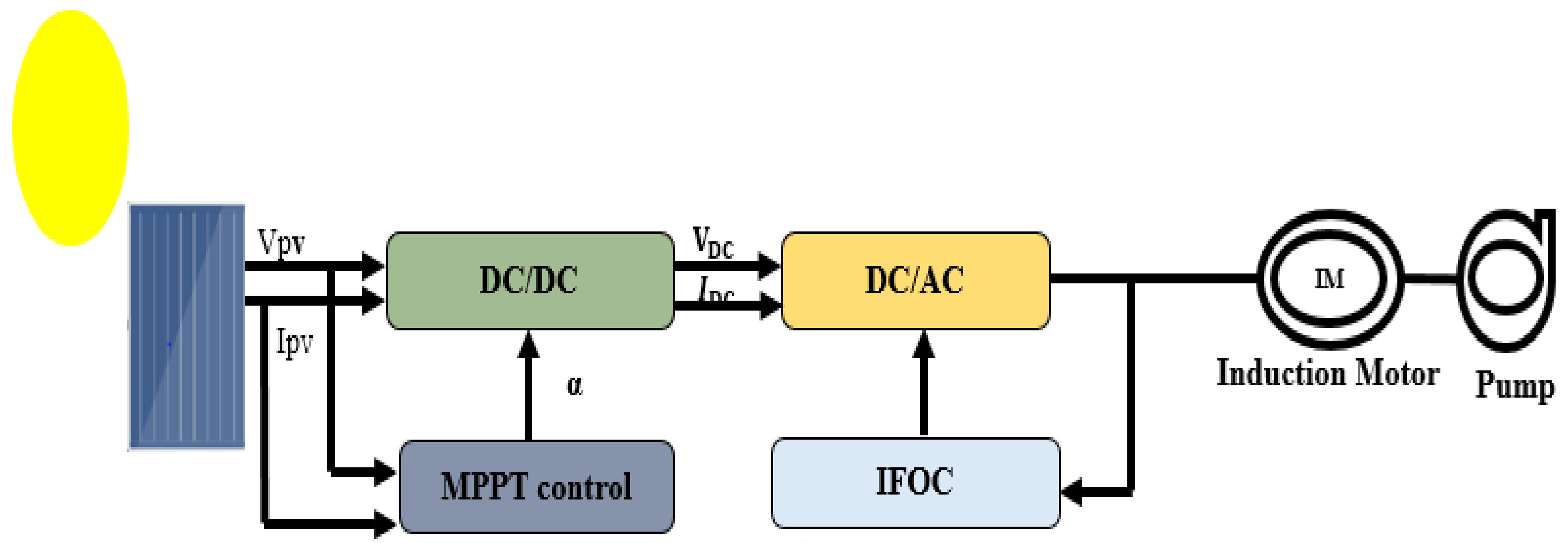
2.1. Description of the PUMP System

The photovoltaic pumping system in Figure 1 consists of two stages. The first is a PV array connected to a boost converter (DC/DC) that ensures operation at maximum power by adjusting the duty cycle through MPPT control techniques to achieve its maximum value with the available radiation. This converter is connected to a voltage source inverter (VSI) which converts DC power to AC power. The second part is responsible for operating the induction motor that drives the pump to extract the water. Indirect field-oriented control is used for the speed and torque of this induction motor [27,28].

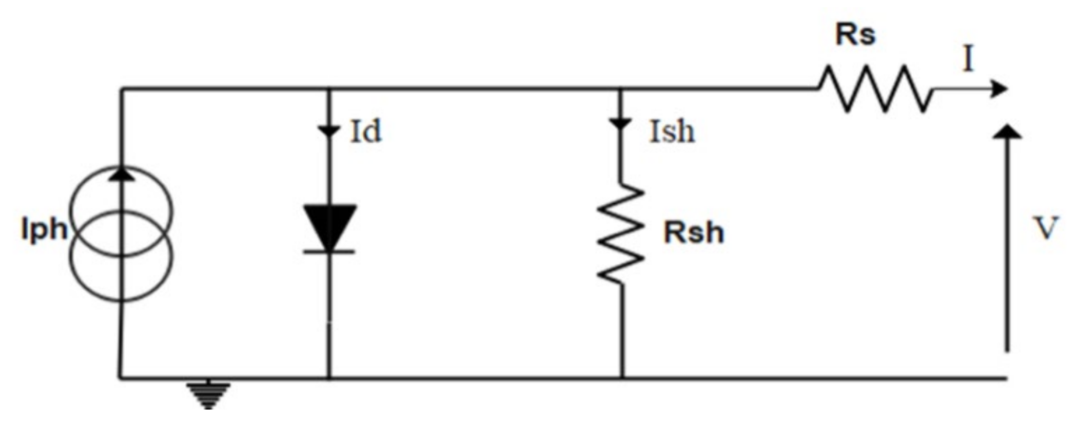
2.2. Equivalent Circuit of a Photovoltaic Cell

The equivalent schematic of the photovoltaic cell presented in Figure 2 contains a generator that is used to produce electricity from sunlight, a diode in parallel that models the PN junction, and two resistors that model the connection losses and the junction leakage currents [15,16,17,18,19,20,21,22,23,24,25,26,27,28,29].
The following equation for the current (I) and voltage (V) describes the characteristics of the PV cell:
I = I PH I s e q V + R s I aKTN s 1 V + R s I R sh
The solar array parameters (CSUN 270-60 M at 25 °C and 1000 W/m2) are described in the Appendix A (Table A1).

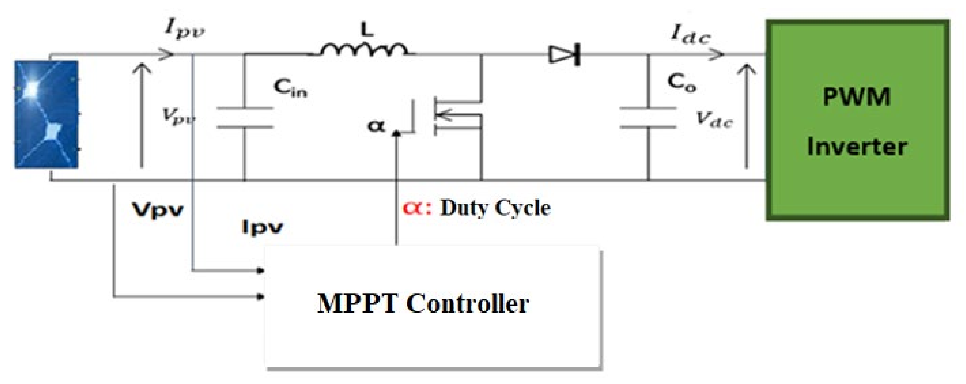
2.3. ”Boost Converter DC/DC”
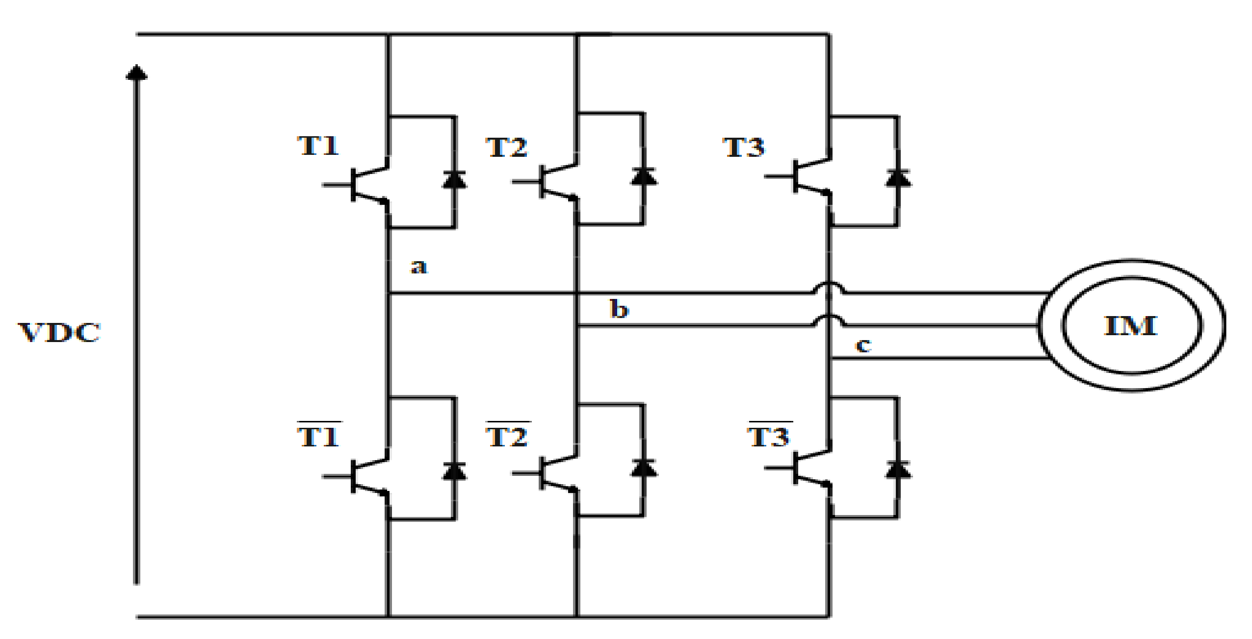
The Figure 3 shown a boost converter placed between the PV panel and the inverter to boost the solar panel’s voltage according to the duty cycle (D) [16,17,18,19,20,21,22,23,24,25,26,27,28,29,30].
The relationship between the PV panel outputs (input of the converter), the converter outputs, and the duty cycle are as follows:
V dc = V pv 1 α
I dc = I pv 1 α
Then, the values of the inductor and capacitor are determined by the following relationships.
L = V PV D Δ I L f s
C = I out D Δ V C f s
where: Δ I L is the ripple current through inductor, 10% to 40%, Δ V C is the ripple voltage across the capacitance, 1% to 2%.
The parameter of the boost converters are presented in the Appendix A (Table A2).

2.4. Inverter

The inverter shown in Figure 4 has the role of converting DC input to three-phase AC output. This inverter delivers a voltage to the machine equal to the current absorbed. The modeling of the inverter is dependent on the state of the switches obtained by the logic values [17,18,19,20,21,22,23,24,25,26,27,28,29,30,31].
Si = 1 if Ti is switched on, else Si = 0 i = (1, 2, 3).
The voltage vector expression is as follows:
Va Vb Vc = 2 3 1 3 1 3 1 3 2 3 1 3 1 3 1 3 2 3 S 1   Vdc 2 S 2   Vdc 2 S 3 Vdc 2

2.5. Induction Motor

The model of the induction motor is facilitated by using Park’s transformation, which works to change the transformation from a fixed ABC coordination to a rotating QP0 coordination [18].
Following simplification, the equation of the IM becomes as follows:
d d   I d s I q s d r q r = γ ω s K T ω r K ω s γ ω r k K T r L m T r 0 1 T r ω s l 0 L m T r ω s l 1 T r I d s I q s d r q r + 1 σ L s 0 0 1 σ   L s 0 0 0 0 V d s V q s
B r = L r R r ,   K = L m σ   L s L r , σ = 1 L m 2 L r   L s ,   γ = R s σ · 1 L s + L m 2 σ · R r L s   L r 2
where V ds V qs ω s are control variables.
The expression for electromagnetic torque is:
T e = 3 2   p   L m L r   dr I qs qr   I ds
The electrical equation associated with the mechanical equation for obtaining the complete model of the system is as follows:
d r dt = T e T r f r   J
where:
  • T e is electromagnetic torque;
  • T r is load torque; and
  • r is motor rotor speed.
The parameters of the induction motor are presented in the Appendix A (Table A3).

2.6. Centrifugal PUMP

A centrifugal pump is a machine that converts mechanical energy into hydraulic energy through centrifugal force. A centrifugal pump has many advantages, including flexibility and relatively high efficiency for large amounts of water [19]. This pump is characterized by some parameters that determine its evaluation.
The first is the load torque of the centrifugal pump.
T pump =   K T 2
where K T represents the constants of the pump
The second is the hydraulic power required to move water from one point to another.
P h = gHQ ρ
where:
  • P h is the power that the pump transmits to the fluid W(watt);
  • H is the total height (m);
  • Q is the flow (m3/s);
  • P is the density of water (1000 kg/m3).
To realize the model, we used the similarity equations, which are as follows:
H = H m ( N N m ) 2
Q t = Q m ( N N m )
where:
  • H m is the maximum height (m);
  • N is the instantaneous speed (rpm);
  • N m is the maximum speed (rpm);
  • Q is the instantaneous flow (m3/s);
  • Q m is the maximum flow (m3/s).

3. Control Strategies of the PVWPS
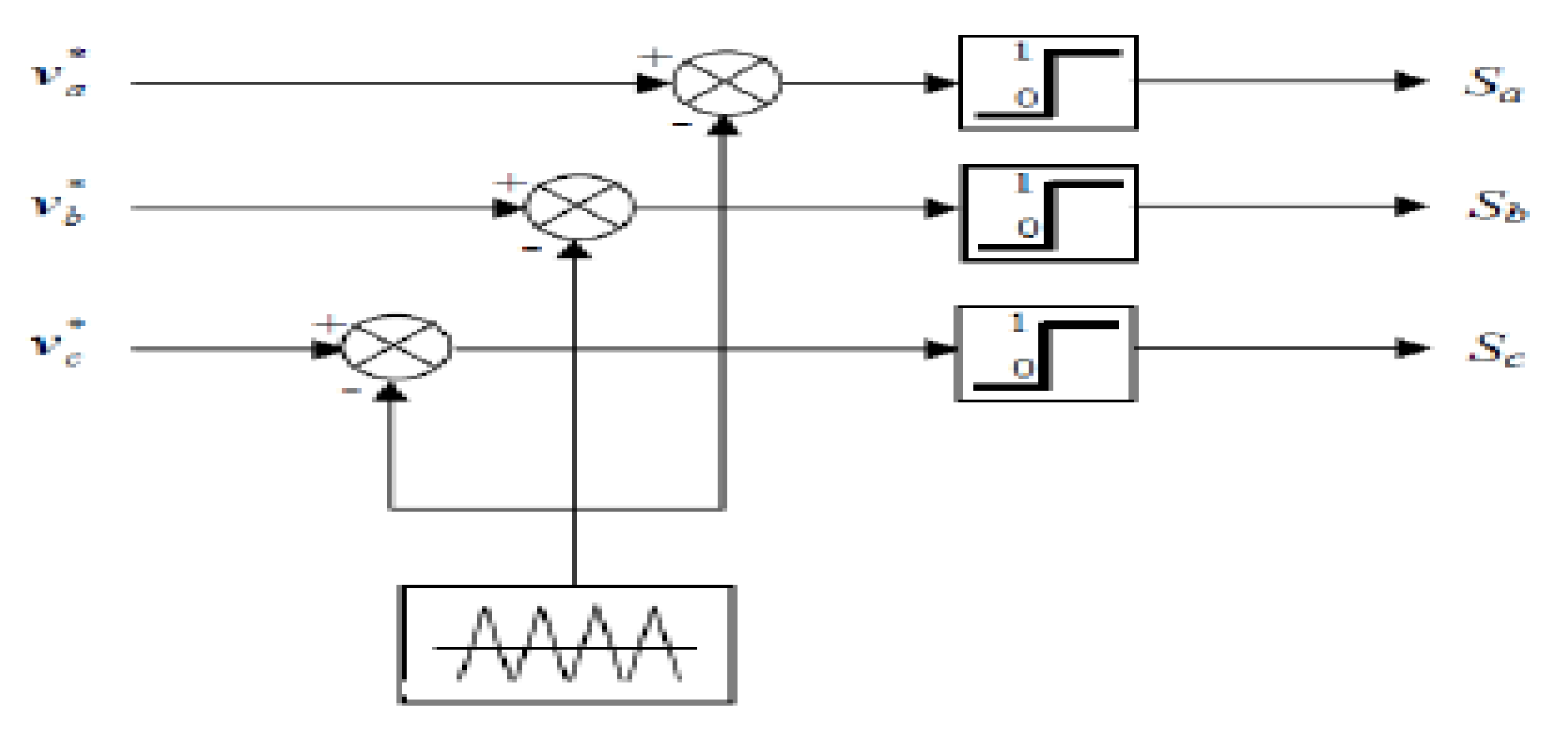
3.1. Control PWM

The PWM is necessary for controlling two VSI levels of the inverter. This technology compares two signals, a triangular signal of high frequency (fp), called a “carrier”, and a reference signal, called a “modulator”, with a frequency fm<< fp. The comparison between these two signals can generate the pulse required to switch the mode of the inverter. Figure 5 shows a comparison of these two signals, which are responsible for controlling the inverter switches [20].

3.2. MPPT Control with variable step Incremental Conductance and Perturb and Observe Algorithms

Several MPPT algorithms have been used in the literature to extract the maximum power from the PV panel with each change in solar irradiance. The most popular of these are perturb and observe and incremental conductance. The purpose of these algorithms is to adjust the duty cycle of a boost converter in such a way that boosted DC voltage can be obtained [21].
“P&O and INC introduce a perturbation (ofs) that has to be either variable or fixed step sizes to reach the maximum powerpoint. Problems may arise with changes in irradiance. With a fixed step size, the oscillation appears to be in a steady-state. However, a variable step size automatically chooses the step sizes, resulting in small oscillations and fast-tracking [22]. In this paper, we used a variable step size for P&O and INC. “

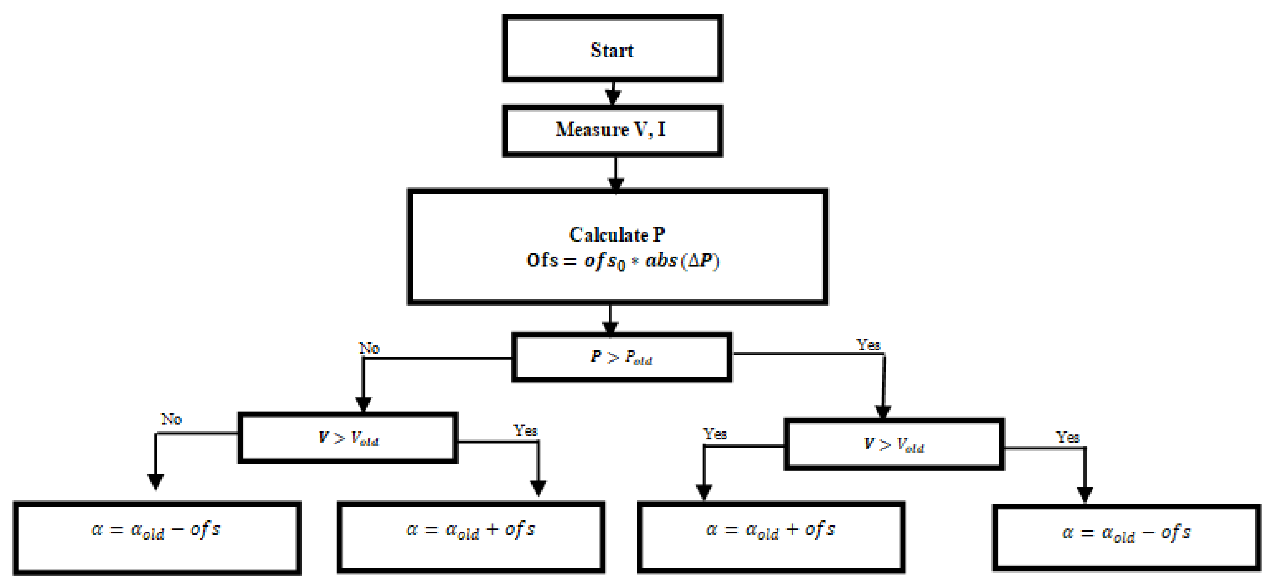
3.2.1. Variable step Perturb and Observe algorithm

The P&O algorithm works by measuring the current and the voltage of the PV, and then the power is calculated and compared to the previous power. Depending on the change in P, the algorithm provides a perturbation ( o f s ) in the duty cycle α. Figure 6 shows a flowchart of the P&O algorithm.
The variable step can be determined by the following relationship:
o f s = o f s 0   Δ P
With changes in Δ P and Δ V , respectively:
  • When dP dV > 0 , the working point is on the left of the MPP;
  • When dP dV = 0 , the working point is on the MPP;
  • When dP dV < 0 , the working point is on the right of the MPP.

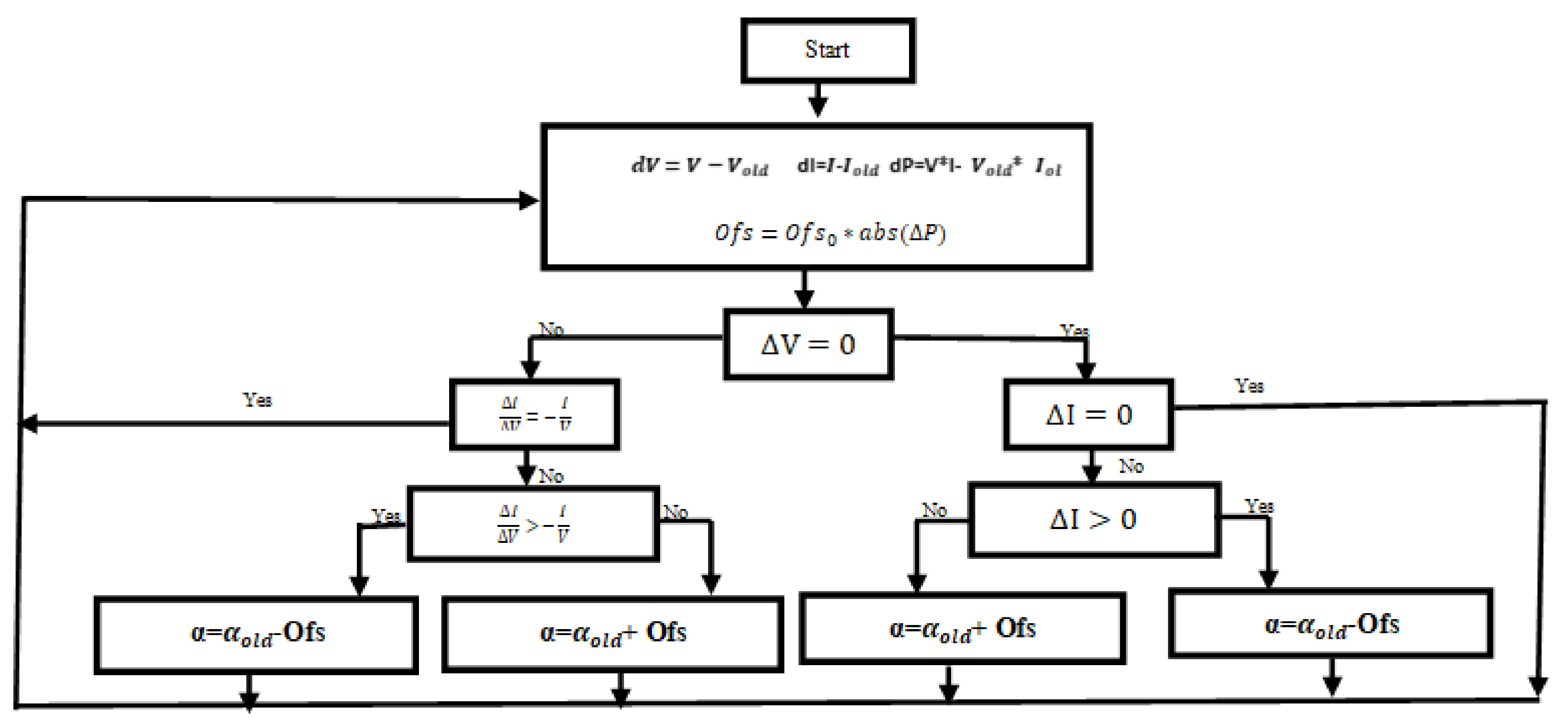
3.2.2. Variable step Incremental Conductance algorithm

INC is based on the derivate of power with respect to voltage d P P V d V P V at MPP, that is d P P V d V P V = 0 . To determine the relationship between the ratio of the derivative of conductance and the instantaneous conductance, the flowchart of the INC algorithm is shown in Figure 7.
d P d V = d V I d V = I + V d I d V = 0
The algorithm of this method can be modeled as follows:
  • Δ V Δ I = V I at MPP;
  • Δ V Δ I > V I Right to MPP;
  • Δ V Δ I < V I Left to MPP.
The step size of this algorithm varies automatically, in a similar way to P&O. this step size increases as the operating point moves away from the MPP and decreases as the operating point approaches the MPP.

3.3. Field-Oriented Control

The induction motor needs to be driven similarly to a DC motor; of the many available controls, field-oriented control is the most commonly used, and works by decoupling the flow and torque into two orthogonal components. This control consists of two types, DFOC and IFOC, and these have been used in many applications [23].
IFOC control consists of aligning the rotor flux (or stator) to one axis of the park reference.
In our case, we direct the flux with the d-axis, which implies
qr = 0   and   r = dr
The following equations are obtained after orientation of the flux, the rotor flux is controlled by acting on the current Ids, while the torque can be controlled with the stator current Iqs:
V ds = σ L s di ds dt + R s i ds σ L s s i qs + Lm L r d r dt
V qs = σ L s di qs dt + R s i qs + σ L s s i ds + L m L r   s r
The expressions for the couple and flux are as follows:
T e = 3 PL m 2 Lr dr I qs
dr = L m I ds
The rotor pulsation is represented by
ω r = L m I qs B r φ rd = ω s p
where σ = 1 L m 2 L s L r and B r = L r R r

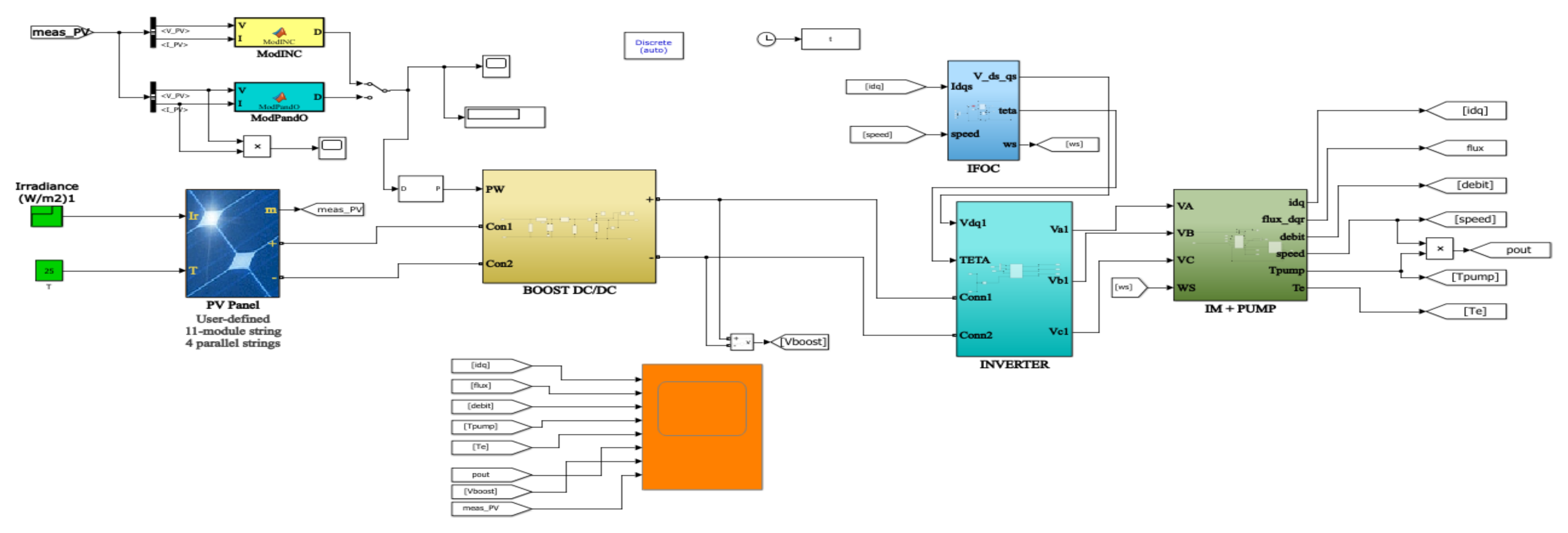
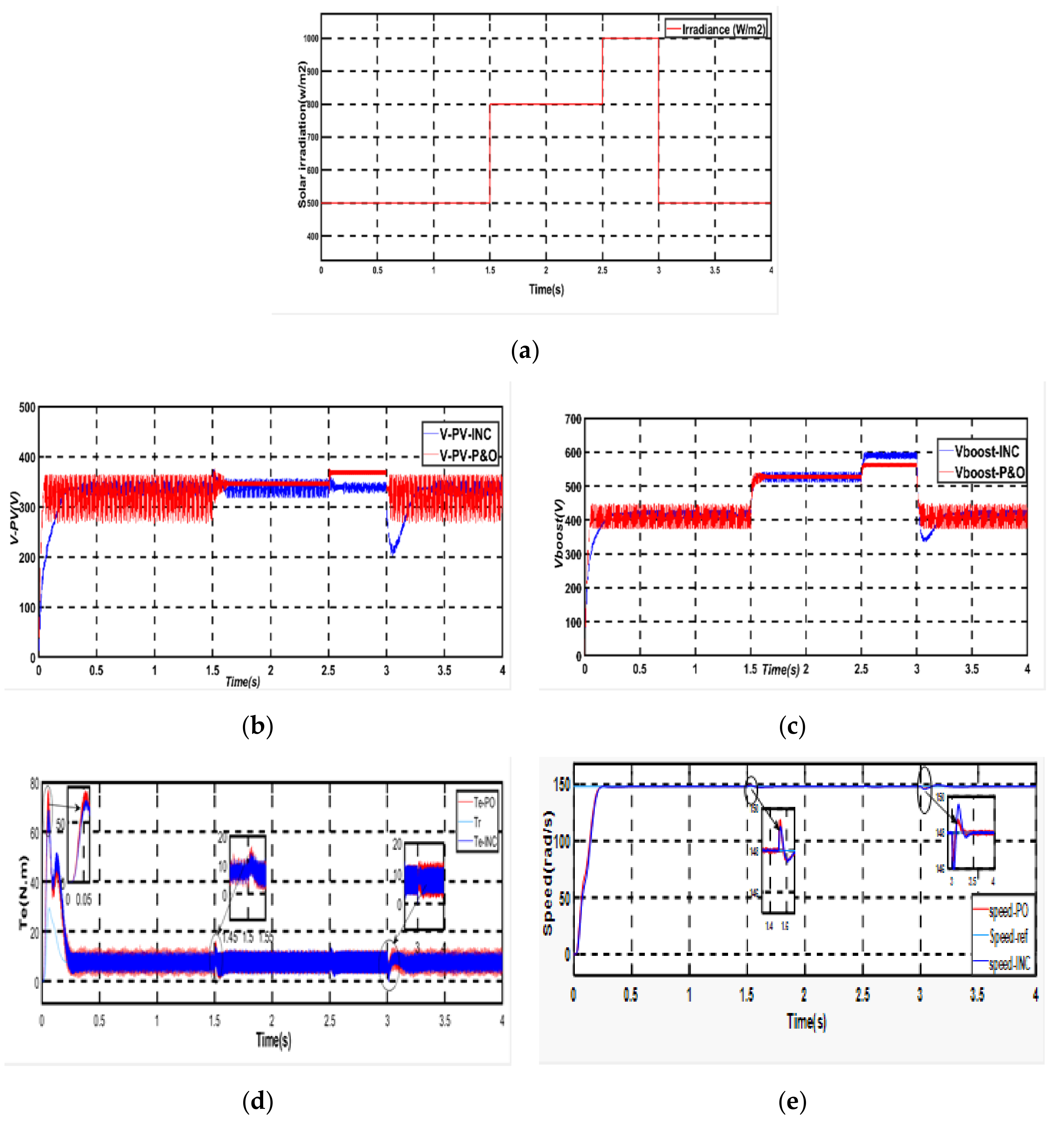
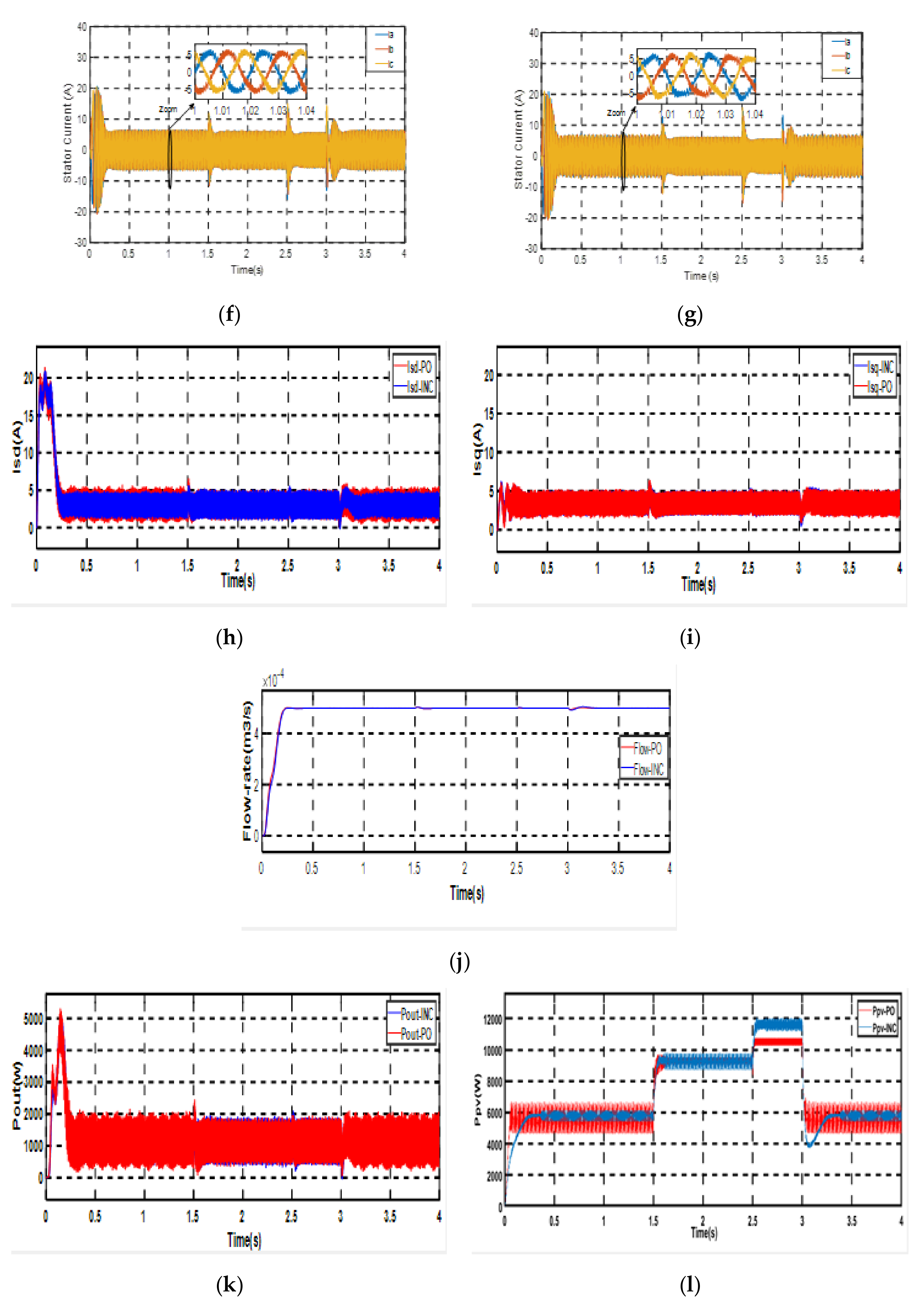
4. Simulation Results

Simulations of the proposed system were performed in Matlab Simulink under different conditions to test the performance of the system, as shown in Figure 8.
In the first step, we chose to change the radiation from 500 W/m2 to 1000 W/m2, before stabilizing at 500 W/m2 while maintaining the temperature to test the effect on PV system performance of sudden changes in radiation, as shown in Figure 9a.
In the second step, the P&O and INC MPPT techniques were applied to the system one by one, using the variable step which is changed with respect to the maximum power at their location.
In Figure 9c,b, first, it can be observed that rapid changes in atmospheric conditions (increase or decrease) produce a change in the output voltage of the PV, leading to changes in the output of the boost converter. Second, based on a comparison between P&O and INC, it can be seen that both methods of MPPT can achieve MPP tracking, but simulating Vboost at (0 to 0.1 s) and (at 3.05 to 3.5 s) shows better results in INC than in P&O, with less oscillation.
In Figure 9d, the variation in electromagnetic torque when the irradiance changes can be observed. It can be seen that for P&O at (0 to 0.05) and (1.45 to 1.55), the deviation is higher than that for INC, leading to greater torque stability in INC than P&O.
Figure 9e shows the rotor speed variation of the induction motor using the two techniques of MPPT. Good responses in starting performance and steady-state can be observed, with good dynamics and negligible overshoots and without static errors. It can also be seen that the rotor speed follows the reference values and is affected by the increase/decrease of irradiation from (500 W/m2 to 1000 W/m2)/(1000 W/m2 to 500 W/m2).
Figure 9f,g shows the variation of stator currents with P&O and INC. It can be seen that the stator currents increase with solar radiation; in addition, it can be seen that the peaks in P&O are greater than those in INC, which can affect system requirements by increasing the cost of the inverter and converter.
Figure 9h,i depict the variation in direct current (Isd) and quadratic current (Isq). It can be seen that Isq changes according to torque variation. In contrast, Isd varies according to flux variation, which shows the strength of the indirect field-oriented control with respect to decoupling between torque and flux.
Figure 9j shows the evolution of the flow rate of the pump. It can be seen that both MPPT techniques have the same results, with barely noticeable distortions more in P&O than INC.
Figure 9k,l show the PV power (Ppv) and motor output power (Pout) with variations in solar irradiation, and it can be seen that the power is dependent on the increase or decrease in irradiation; in addition, the comparison between (Ppv) and (Pout), which is Pout = Ppv, shows that losses due to motor efficiency are system losses.

5. Conclusions

In this work, photovoltaic water pumping performance was successfully improved. Based on simulation studies under sudden changes in climatic conditions, the performance of the system using IFOC was analyzed. A comparison between INC and P&O with the implementation of a variable step was made. The results of this comparison showed that the P&O algorithm presented oscillations around the optimal value compared with INC, which exhibited less oscillation and behaved better during sudden changes in irradiation.
In addition, the operation of the motor with incremental conductance achieved better results in the simulation than perturb and observe with respect to the stator current and electromagnetic torque of an induction motor. P&O exhibited some undesirable deviations, leading to increased peaks in the converter and inverter, thus increasing the cost of the system components.

Author Contributions

Conceptualization, I.S.; methodology, M.K., B.M.; software, M.s.A., S.M.; validation, I.S., M.L.; formal analysis, I.S.; investigation, I.S.; resources, I.S.; data curation, I.S.; writing—original draft preparation, I.S.; writing—review and editing, M.M., J.F.A.-A., S.M., B.M.; visualization, M.K.; supervision, J.F.A.-A., S.M., B.B., M.s.A., M.M.; project administration, B.B.; funding acquisition, J.F.A.-A. All authors have read and agreed to the published version of the manuscript.

Funding

Taif University Researchers Supporting Project number (TURSP-2020/211), Taif University, Taif, Saudi Arabia.

Institutional Review Board Statement

Not applicable.

Informed Consent Statement

Not applicable.

Data Availability Statement

Not applicable.

Acknowledgments

The authors would like to thank Taif University Researchers Supporting Project number (TURSP-2020/211), Taif University, Taif, Saudi Arabia for the support.

Conflicts of Interest

The authors declare no conflict of interest.

Appendix A

Table A1. Parameters of the PV module.
PV ParametersSymbolValues
Maximum PowerPmp270,116 W
Open circuit VoltageVoc37.9 V
Voltage at MPPT
Short-circuit current
Cells per module
Vmp
Isc
Ncell
30.8 V
9.07 A
8.7 A
Table A2. Parameters of the boost converter.
Boost ParametersSymbolValues
Input voltageVin338.8 V
Output voltageVout600 V
Duty cycle
Inductance
Output and input
capacitor
D
L
Cin = Cout
0.43
3 mh
6 × 10⁻⁴ F
Table A3. Parameters of the induction motor.
IM ParametersSymbolValues
Nominal powerPn1.5 kw
Nominal voltageVn220/380
Rated speed1420 rpm
Nominal frequencyfn50 Hz
Stator resistanceRs4.850 Ω
Rotor resistanceRr3.805 Ω
Stator inductanceLs0.274 H
Rotor inductanceLr0.274 H
Mutual inductionLm0.258 H
Number of pole pairsp2

References

  1. Feraga, C.-E.; Bouldjedri, A. Performance of a Photovoltaic Pumping System Driven by a Single Phase Induction Motor Connected to a Photovoltaic Generator. Autom. Časopis Autom. Mjer. Elektron. Računarstvo Komun. 2016, 57, 163–172. [Google Scholar] [CrossRef] [Green Version]
  2. Singla, C.; Pahwa, V.; Kumar, D. Optimum MPPT Technique for the PV based Field Oriented Control of Induction Motor Feeding Centrifugal Pump. Indian J. Sci. Technol. 2016, 9, 1–8. [Google Scholar] [CrossRef] [Green Version]
  3. Moubarak, A.; El-Saady, G.; Ibrahim, E.N. Variable Speed Photovoltaic Water Pumping Using Affinity Laws. J. Power Energy Eng. 2017, 5, 50–71. [Google Scholar] [CrossRef] [Green Version]
  4. Khlifi, M.A. Study and Control of Photovoltaic Water Pumping System. J. Electr. Eng. Technol. 2016, 10, 350–371. [Google Scholar] [CrossRef] [Green Version]
  5. Amir, A.; Selvaraj, J.; Rahim, N.A. Study of the MPP tracking algorithms: Focusing the numerical method techniques. Renew. Sustain. Energy Rev. 2016, 62, 350–371. [Google Scholar] [CrossRef]
  6. Gupta, A.; Chauhan, Y.K.; Pachauri, R.K. A comparative investigation of maximum power point tracking methods for solar PV system. Sol. Energy 2016, 136, 236–253. [Google Scholar] [CrossRef]
  7. Anna, M.; Immanuel, S. MPPT based stand-alone water pumping system. In Proceedings of the International Conference on Computer, Communication and Electrical Technology (ICCCET), Tirunelveli, India, 18–19 March 2011. [Google Scholar]
  8. Motahhir, A.S.; Ghzizal, E.; Sebti, S.; Derouich, A. Modeling of Photovoltaic System with modified Incremental Conductance Algorithm for fast changes of irradiance. Int. J. Photoenergy 2018, 2018, 13. [Google Scholar] [CrossRef]
  9. Saidi, K.; Maamoun, M.; Bounekhla, M. A new high performance variable step size perturb-and-observe MPPT algorithm for photovoltaic system. Int. J. Power Electron. Drive Syst. 2019, 10, 1662–1674. [Google Scholar] [CrossRef]
  10. Li, C.; Chen, Y.; Zhou, D.; Liu, J.; Zeng, J. A High-Performance Adaptive Incremental Conductance MPPT Algorithm for Photovoltaic Systems. J. Energ. 2016, 9, 288. [Google Scholar] [CrossRef] [Green Version]
  11. Poompavai, T.; Kowsalya, M. Control and energy management strategies applied for solar photovoltaic and wind energy fed water pumping system: A review. Renew. Sustain. Energy Rev. 2018, 107, 108–122. [Google Scholar] [CrossRef]
  12. Kumar, R.; Singh, B. BLDC motor-driven solar PVArray-fed water pumping system employing zeta converter. IEEE Trans. Ind. Appl. 2016, 52, 2315–2322. [Google Scholar] [CrossRef]
  13. Mudlapur, A.; Ramana, V.V.; Damodaran, R.V.; Balasubramanian, V.; Mishra, S. Effect of partial shading on PV fed induction motor water pumping systems. IEEE Trans. Energy Convers. 2019, 34, 530–539. [Google Scholar] [CrossRef]
  14. Kiran, N. Indirect Vector Control of Three Phase Induction Motor using PSIM. Bull. Electr. Eng. Inform. 2014, 3, 15–24. [Google Scholar] [CrossRef]
  15. Saeed, M.A.; Kim, S.H.; Kim, H.; Liang, J.; Woo, H.Y.; Kim, T.G.; Yan, H.; Shim, J.W. Indoor Organic Photovoltaics: Optimal Cell Design Principles with Synergistic Parasitic Resistance and Optical Modulation Effect. Adv. Energy Mater. 2021, 11, 2003103. [Google Scholar] [CrossRef]
  16. Errouha, M.; Derouich, A.; Motahir, S.; Zamzoum, O. Optimal Control of Induction Motor for Photovoltaic Water Pumping System. Technol. Econ. Smart Grids Sustain. Energy 2020, 5, 6. [Google Scholar] [CrossRef] [Green Version]
  17. Yahyaoui, I. Specifications of Photovoltaic Pumping Systems Sizing, Fuzzy Energy Management Specifications of Photovoltaic Pumping Systems; Elsevier: Amsterdam, The Netherlands, 2016. [Google Scholar]
  18. Wang, F.; Zhang, Z.; Mei, X.; Rodríguez, J.; Kennel, R. Advanced control strategies of induction machine: Field oriented control, direct torque control and model predictive control. Energies 2018, 11, 120. [Google Scholar] [CrossRef] [Green Version]
  19. Rawat, R.; Kaushik, S.C.; Lamba, R. A review on modeling, design methodology and size optimization of photovoltaic based water pumping, standalone and grid connected system. Renew Sustain. Energy Rev. 2016, 57, 1506–1519. [Google Scholar] [CrossRef]
  20. Gulyaev, A.; Fokin, D.; Ten, E.; Vlasyevsky, V. PWM algorithms synthesis. Procedia Eng. 2016, 165, 1529–1535. [Google Scholar] [CrossRef]
  21. Motahhir, S.; El Hammoumi, A.; El Ghzizal, A. The Most Used MPPT Algorithms: Review and the Suitable Low-cost Embedded Board for Each Algorithm. J. Clean Prod. 2019, 246, 118983. [Google Scholar] [CrossRef]
  22. Motahhir, S.; El Hammoumi, A.; El Ghzizal, A. Photovoltaic system with quantitative comparative between an improved MPPT and existing INC and P&O methods under fast varying of solar irradiation. Energy Rep. 2018, 4, 341–350. [Google Scholar]
  23. Hiware, R.S.; Chaudhari, J.G. Indirect Field Oriented Control for Induction Motor. In Proceedings of the International Conference on Emerging Trends in Engineering Technology, Port Louis, Mauritius, 18–20 November 2011. [Google Scholar]
  24. Bossoufi, B.; Karim, M.; Lagrioui, A.; Mohammed, T.; EL Hafyani, M.L. Backstepping control of DFIG Generators for Wide-Range Variable-Speed Wind Turbines. IJAAC Int. J. Autom. Control 2014, 8, 122–140. [Google Scholar] [CrossRef]
  25. Bossoufi, B.; Karim, M.; Lagrioui, A.; Mohammed, T. FPGA-Based Implementation nonlinear backstepping control of a PMSM Drive. IJPEDS Int. J. Power Electron. Drive Syst. 2014, 4, 12–23. [Google Scholar] [CrossRef]
  26. Bossoufi, B.; Karim, M.; Lagrioui, A. FPGA-Based Implementation Sliding Mode Control and nonlinear Adaptive Backstepping control of a Permanent Magnet Synchronous Machine Drive. Wseas Trans. Syst. Control. 2014, 9, 86–100. [Google Scholar]
  27. Narjess, S.; Trabelsi, R.; Gdaim, S.; Bossoufi, B.; Mimouni, M.F. Backstepping control of induction motor using Xilinx System Generator: FPGA-based implementation. Int. J. Emerg. Sci. 2013, 3, 289–302. [Google Scholar]
  28. Bossoufi, B.; Karim, M.; Ionita, S.; Lagrioui, A. Nonlinear Non Adaptive Backstepping with Sliding-Mode Torque Control Approach for PMSM Motor. J. Electr. Syst. 2012, 8, 236–248. [Google Scholar]
  29. Bossoufi, B.; Karim, M.; Ionita, S.; Lagrioui, A. The Optimal Direct Torque Control of a PMSM drive: FPGA-Based Implementation with Matlab & Simulink Simulation. J. Theor. Appl. Inf. Technol. 2011, 28, 63–72. [Google Scholar]
  30. Bossoufi, B.; Karim, M.; Ionita, S.; Lagrioui, A.; Gabriel, I. Matlab & Simulink Simulation with FPGA-Based Implementation Sliding Mode Control of a Permanent Magnet Synchronous Machine Drive. Wseaa Trans. Syst. Control 2011, 6, 92–103. [Google Scholar]
  31. Bossoufi, B.; Karim, M.; Ionita, S.; Lagrioui, A. Indirect Sliding Mode Control of a Permanent Magnet Synchronous Machine: FPGA-Based Implementation with Matlab & Simulink Simulation. J. Theor. Appl. Inf. Technol. 2011, 29, 32–42. [Google Scholar]
Figure 1. Functional principle of a solar pump.
Electronics 10 03076 g001
Figure 2. Photovoltaic cell circuit.
Electronics 10 03076 g002
Figure 3. Equivalent circuit of the boost converter.
Electronics 10 03076 g003
Figure 4. Three-phase inverter.
Electronics 10 03076 g004
Figure 5. The control of the Inverter switch.
Electronics 10 03076 g005
Figure 6. Flowchart of variable step perturb and observe algorithm.
Electronics 10 03076 g006
Figure 7. Flowchart of the variable step incremental conductance algorithm.
Electronics 10 03076 g007
Figure 8. Solar pump simulation design.
Electronics 10 03076 g008
Figure 9. (a) Solar radiation. (b) Output voltage of the PV. (c) Output voltage of the boost converter. (d) Torque Evolution (N.m). (e) Mechanical Speed (f) Stator current—P&O. (g) Stator current—INC. (h) Current Isd. (i) Current Isq. (j) Flow pump evolution (m3/s). (k) Motor output power. (l) Output voltage of the PV.
Electronics 10 03076 g009aElectronics 10 03076 g009b
Publisher’s Note: MDPI stays neutral with regard to jurisdictional claims in published maps and institutional affiliations.

