Abstract
This article deals with the application of differential geometry to the array manifolds of non-uniform linear antenna array (NULA) when estimating the direction of arrival (DOA) of multiple sources present in an environment using far field approximation. In order to resolve this issue, we utilized a doublet linear antenna array (DLA) comprising two individual NULAs, along with a proposed algorithm that chooses correct directions of the impinging sources with the help of the prior knowledge of the ambiguous directions calculated with the application of differential geometry to the manifold curves of each NULA. The algorithm checks the correlation of the estimated direction of arrival (DOAs) by both the individual NULA with its corresponding ambiguous set of directions and chooses the output of the NULA, which has a minimum correlation between their estimated DOAs and corresponding ambiguous DOAs. DLA is designed such that the intersection of all the ambiguous set of DOAs among the individual NULAs are null sets. DOA of sources, which imping signals from different directions on the DLA, are estimated using three direction finding (DF) techniques, such as, genetic algorithm (GA), pattern search (PS), and a hybrid technique that utilizes both GA and PS at the same time. As compared to the existing techniques of ambiguity resolution, the proposed algorithm improves the estimation accuracy. Simulation results for all the three DF techniques utilizing the DLA along with the proposed algorithm are presented using MATLAB. As compared to the genetic algorithm and pattern search, the intelligent hybrid technique, such that, GA–PS, had better estimation accuracy in choosing corrected DOAs, despite the fact that the impinging DOAs were from ambiguous directions.
1. Introduction
Smart antennas or antenna arrays are one of the interesting areas in the field of wireless communication and electromagnetics. Smart antennas are adaptive in nature, being able to be effectively utilized in scenarios when dealing with multi-user communication system [1]. In the case of one-dimensional (1-D) systems, smart antennas comprise a linear array of radiating antennas, usually a half-wavelength apart. Due to their adaptive nature, smart antennas can steer their main beam in every desirable direction of interest [2], while the nulls could be steered in any undesired directions [3,4,5]. DOA estimation of multiple sources that imping signals on array’s elements could be effectively achieved using smart antennas, having many applications in the field of wireless communication systems, radar systems, sonar systems, and acoustics [6,7,8,9]. In terms of estimating DOA using antenna array, many high-resolution algorithms are presented in literature such as multiple signal classification (MUSIC) [10], min-norm [11], estimation of signal parameters via rotational invariance techniques (ESPRIT) [12], and space-alternating generalized maximization-expectation (SAGE) [13]. However, performance of all the high-resolution direction-finding (DF) techniques [10,11,12,13] degrades and generates an ambiguous error when estimating the DOA of different sources if the separation between antenna array elements exceeds more than half the carrier wavelength [14].
In case of uniform linear arrays (ULAs), the distance between the antenna elements is fixed, usually half of the wavelength, such that, no antenna element is missing with a fixed array aperture. However, for an antenna array with same aperture as ULA, but with a smaller number of elements, high resolution could be achieved with low cost and less complexity [15]. In order to achieve such NULAs, distance between the antenna elements must be increased beyond half of the wavelength, such that, spatial variance is maximized. Utilizing NULAs, although the spatial resolution improves despite having a smaller number of array elements, the problem of directional ambiguities arises in the array system. There is a tradeoff that exists between resolution and directional ambiguities in linear antenna arrays, such that, NULA with same aperture as ULA and having a smaller number of array elements has better resolution capabilities but suffers from the problem of directional ambiguities. The problem here that needs to be addressed is resolving the directional ambiguities that exist in the manifold of NULAs due to their geometries.
The remaining paper is organized as follows: Section 2 describes the literature review and motivation behind the work presented; Section 3 presents data model for the proposed doublet antenna array; Section 4 describes proposed methodologies, including three direction-finding techniques for resolving directional ambiguities; Section 5 shows simulation results for three different scenarios considering three, four, and five sources; Section 6 presents performance comparison; and Section 7 concludes the article.
2. Literature Review
For NULAs with elements spacing greater than half wavelength, the array offers directional ambiguities while estimating DOA of sources. Under such circumstance, the antenna array response vector(s) become a linear combination of other response vectors and the problem of rank deficiency is said to arise, such that, the array manifold matrix is said to be singular, and the antenna array is unable to differentiate between different sources and thus an unresolvable situation arises. In order to resolve the issue of rank deficiency, the authors in [16] presented an array interpolation technique that successfully extracted the observational data from the elements of virtual uniform linear array (VULA) with the application of linear interpolation to the observed data from the elements of a real sparse LA. Selection criterion of coefficients are based on minimized interpolation error to various impinging signals from the specific angular sector. The problem with this technique is that the angular sector needs to be identified. In order to resolve the ambiguity in manifold, the authors in [17] used fully augmentable antenna arrays and proposed a generalized augmentation approach. Ambiguity is resolved successfully by the approximation that the desired fisher matrix must be non-singular [18]. The problem with this technique is that it requires large number of snapshots and high SNR (signal to noise ratio) when the ambiguous and unambiguous sources have minimum separation or are closely spaced. Reference [19] proposed the Wiener array interpolation method, which uses calibration angles for construction of the steering matrix and achieves optimum solution with least MSE (minimum square error) with ML (maximum likelihood) method for the estimation of SNR. The Wiener array interpolation method works well; however, it requires the initial direction of arrival of sources. In an attempt to improve the covariance matrix, the authors in [20] further improved the Toeplitz completion method by using a direct augmentation approach (DAA). However, the proposed method did not assure that the positive semidefinite augmented covariance matrix must be achieved. The authors of [21,22] proposed an iterative direct augmentation approach (IDAA) for the construction of a positive semidefinite augmented covariance matrix. However, due to the complex and complicated iterative procedures, it does not provide the global convergence. In [23], the authors proposed a DLA consisting of two different LAs, whose antenna locations are decided in accordance with some specific rules in order to avoid ambiguity. An efficient algorithm is proposed, which effectively chooses the unambiguous direction of sources estimated via genetic algorithm (GA) as a direction-finding technique. The proposed work in [23] resolved the problem of ambiguity but had lower estimation accuracy, due to the fact that it uses only GA as a direction-finding technique. Table 1 shows the summary of weaknesses regarding the related work.

Table 1.
Summary of limitations/weaknesses of related work.
Study Contributions
After we carried out detailed analysis of the already existing solutions provided in the literature to resolve directional ambiguities, we observed that the proposed solutions in literature require high computational cost as they involve complex mathematics and are based on hard problems. These techniques mostly suffer from issues such as rank deficiency and do not guarantee the required positive semidefinite augmented covariance matrix. Moreover, these techniques are constrained, dependent, and do not provide a guaranteed resolution of direction ambiguities for any generalized array structure. Moreover, the recent work presented for ambiguity resolution in [23] uses a DLA along with GA as a DF technique, which works well, but unfortunately its estimation accuracy is lower, due to the fact that GA has a heuristic nature that does not necessarily guarantee estimation accuracy. We need to extend the existing work for effective and accurate estimation of DOA of sources at the output of the array without having any directional ambiguities among multiple sources.
Motivated by the aforementioned objectives, we proposed an algorithm for resolution of ambiguities based on hybrid heuristic computing, which hybridized heuristic techniques such as GA with pattern search (PS).
3. Data Model
Consider L narrow band sources in the far field, which are impinging signals on the doublet linear antenna array (DLA), as shown in Figure 1. The DLA consists of two individual non-uniform linear antenna arrays (NULAs), whose antenna elements are non-uniformly spaced and are located at particular spacing in terms of wavelengths. The location of the elements of both the individual NULAs are selected such that none of the ambiguous DOAs become common between both the arrays. Every element of the DLA is placed according to the rule discussed in [23].
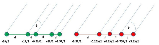
Figure 1.
Doublet linear antenna array comprising of two LAs.
Observation vector received at the output of each individual antenna array can be written as
where is the observation received from all the sources at antenna 1, is the observation received from all the sources at antenna 2, and similarly is the observation received from all the sources at Mth antenna, such that,
where are the amplitudes and are the azimuth angles of the impinging signals on the DLA from far field, and are the number of sources. Moreover, is the separation or distance between the elements of the antenna array, and is the wave number. From Equations (2)–(5), the unknown parameters of interest are the amplitudes and azimuth angles of all the sources. Here, the problem is to jointly estimate the amplitudes and directions of all the impinging signals without any directional ambiguity using intelligent hybrid computing technique.
4. Proposed Methodologies
4.1. Direction Finding Techniques
In this particular section, an overview and a logical flow diagram including different parameters for genetic algorithm (GA) and pattern search (PS) algorithm utilized for the joint estimation of amplitudes and direction of arrival of sources are presented. Genetic algorithm (GA) is a heuristic technique belonging to a family of evolutionary computing inspired from natural phenomena and is very reliable among all the heuristic mathematical solvers [24,25]. Due to its ease in implementation, simplicity, and lesser probability of getting stuck in local minima, GA has been widely used in the field of communication [26], antenna array processing [27], and soft computing [28]. Pattern search (PS) or derivative-free search algorithm is used in optimization and does not demand the gradient of the problem. PS is used for the computation of those sequence of points that obtain an optimum point. In every step of the technique, it looks for a set of points called a mesh of points around the optimum point that is obtained in the previous step. The mesh of points is obtained by adding the current point achieved with a scalar multiple of vectors known as a pattern [29]. If the algorithm achieves a point in the mesh such that it enhances the required objective function at the current point, then this newly achieved point is said to be the current point for the next step. PS method is very efficient for problems related to optimization such as globally convergent augmented lagrangian and bound constrained minimization [30].
4.2. Working of the Proposed Algorithm
Firstly, all the possible ambiguous set of DOAs for the DLA are calculated using the technique discussed in [23]. After all the ambiguous sets of DOAs for the DLA are achieved, the data are stored as they will always remain unchanged for the same DLA unless the position of any of the element becomes changed. When the DLA is used for estimation of direction of sources, if any of the sources imping signals on the DLA, the direction-finding techniques such as GA, PS, and hybrid GA–PS estimate the direction of arrival of all the sources. After the estimation process, the algorithm compares all the estimated DOAs by each individual linear array with its own ambiguous sets of directions, and the decision of choosing corrected DOAs is taken as follows if
- (a)
- Estimated DOAs by both the individual NULAs do not belong to its corresponding ambiguous set of DOAs, which means that no directional ambiguity exists, and the algorithm can select output of any of the individual NULAs.
- (b)
- Estimated DOAs obtained by the first NULA belong to their own ambiguous set of DOAs or its subset, then the algorithm chooses output of the second NULA. It is because the impinging DOA of sources are ambiguous for the first NULA.
- (c)
- Estimated DOAs obtained by the second NULA belong to their own ambiguous set of DOAs or its subset, then the algorithm chooses output of the first NULA. It is because the impinging DOA of sources are ambiguous for the second NULA.
- (d)
- Estimated DOAs by both the arrays, such that, first and second array partially belong to their corresponding ambiguous set of DOAs, then the algorithm chooses output of that respective NULA, whose estimated DOAs have minimum correlation with their ambiguous set of DOAs.
We used the GA, PS, and hybridized approaches, such that, GA–PS, for estimating corrected DOAs of multiple sources that impinged signals on the DLA, as shown in Figure 1. Flow chart of the intelligent hybrid computing technique is presented in Figure 2. The following steps describe the hybrid GA–PS.
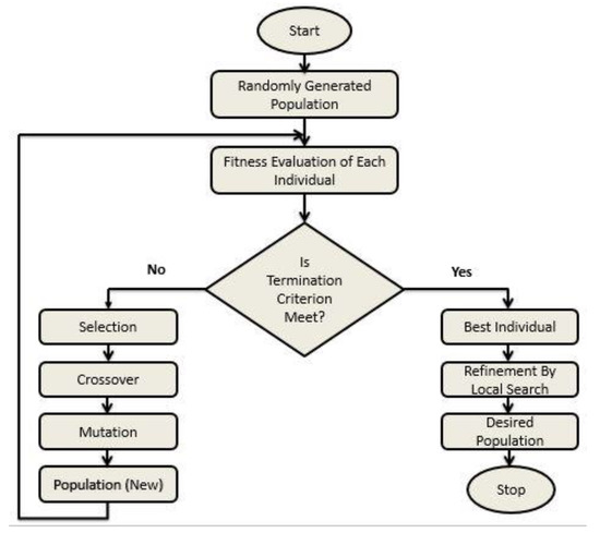
Figure 2.
Flow diagram for hybrid GA–PS.
Step I: From Equations (2)–(5), we find that the unknown parameters of interest are and , and therefore number of particles are generated at random, which are listed in Table 2. Moreover, the parameters for crossover, mutation, and elitism are listed in Table 3, which could be utilized for reproduction of the next generation.
Table 2.
Randomly generated particles.
Table 3.
Parameters utilized for genetic algorithm and pattern search.
Step II: Fitness calculation: Fitness function is evaluated using the given formula, i.e.,
where
where is the actual observation received at the antenna array, and is the estimated observation using intelligent hybrid algorithm. Candidate solution with minimum error will have better fitness. This candidate will be given preference, as its fitness function is better than the others.
Step III: Termination criterion: The termination point is achieved if one of the following conditions are true:
- If minimum error becomes greater than the error threshold, such that,
Or
- If a maximum number of cycles are completed.
Step V: Refinement: Further tuning is performed using Pattern search algorithm.
5. Results and Discussion
This section provides various simulation results for joint estimation of amplitude and DOA of multiple sources, which impinge signals from far field on the DLA, as shown in Figure 1. We used three different direction-finding (DF) techniques along with the algorithm presented in [23] for estimation of amplitude and direction, such that, GA, PS, and hybridized GA with PS. The doublet antenna array used in Figure 1 is composed of two non-uniform linear arrays placed along the x-axis. Mean square error (MSE) was used as a fitness evaluation function, which is a basic criterion here for joint estimation of both the amplitudes and DOA of sources. All the simulations were performed using Matlab R2014b.
5.1. Impinging Sources Belonging to Ambiguous Set of Array 1
In case of ambiguous DOA belonging to array 1, estimation accuracies of all the three techniques used, such that, GA, PS, and GA–PS, are presented for a noiseless environment considering three different cases. It should be noted that all the ambiguous set of DOAs were calculated using differential geometry, the technique used in [23], and were not described and calculated here for simplicity.
Case A. Amplitude and direction estimation for three sources.
We assumed three sources that are impinging signals on the DLA, as shown in Figure 1 from far field. The amplitudes of all the three sources, , were taken as unity (for simplicity), such as, , while the direction of arrival for the first source was , for the second source was , and for the third source was , which was an ambiguous set of DOAs for the first array. All three techniques, such as, GA, PS, and GA–PS, worked well, although impinging DOAs belonged to the ambiguous set. It can be seen from Table 4 that the hybridized GA–PS when compared to GA and PS attained better DOAs.
Table 4.
Comparison of DOAs achieved using GA, PS, and GA–PS.
Case B. Amplitude and direction estimation for four sources.
We assumed four sources that are imping signals on the doublet antenna array in Figure 1. Results for all the three DF techniques, such as, GA, PS, and GA–PS, are presented in Table 5. It can be seen that hybridized GA–PS when compared to GA and PS attained better DOAs.
Table 5.
Comparison of DOAs achieved using GA, PS, and GA–PS.
Case C. Amplitude and direction estimation for five sources.
In this case, we assumed five sources that are imping signals on the doublet antenna array in Figure 1. Results for all the three techniques, such as, GA, PS, and GA–PS are presented in Table 6. Hybridized GA–PS achieved better DOAs when compared to GA and PS. Performance of all the DF techniques degraded when the number of sources exceeded the number of antenna elements.
Table 6.
Comparison of DOAs achieved using GA, PS, and GA–PS.
5.2. Impinging Sources Belonging to Ambiguous Set of Array 2
For the case of ambiguous DOA belonging to array 2, estimation accuracies of all the three techniques used, such as, GA, PS, and GA–PS, are presented for a noiseless environment considering three different cases. It should be noted that all the ambiguous set of DOAs were calculated using differential geometry, the technique used in [23], and were not described and calculated here for simplicity.
Case A. Amplitude and direction estimation for three sources.
We assumed three sources that are imping signals on the DLA in Figure 1 from far field. The amplitudes of all the three sources, , were taken as unity (for simplicity), i.e., , while the direction of arrival for the first source was , for the second source was , and for third source was , which was an ambiguous set of DOAs for the second NULA. All the three techniques, i.e., GA, PS, and GA–PS worked well, although impinging DOAs belonged to the ambiguous set. It can be seen from Table 7 that the hybridized GA–PS when compared to GA and PS attained better DOAs.
Table 7.
Comparison of DOAs achieved using GA, PS, and GA–PS.
Case B. Amplitude and direction estimation for four sources.
We assumed four sources that are imping signals on the doublet antenna array in Figure 1. Results for all the three DF techniques, such that, GA, PS, and GA–PS, are presented in Table 8. It can be seen that hybridized GA–PS when compared to GA and PS attained better DOAs.
Table 8.
Comparison of DOAs achieved using GA, PS, and GA–PS.
Case C. Amplitude and direction estimation for five sources.
In this case, we assumed five sources that are imping signals on the doublet antenna array in Figure 1. Results for all the three techniques, such that, GA, PS, and GA–PS, are presented in Table 9. Hybridized GA–PS achieved better DOAs when compared to GA and PS. Performance of all the DF techniques degraded when the number of sources exceeded the number of antenna elements.
Table 9.
Comparison of DOAs achieved using GA, PS, and GA–PS.
5.3. Impinging Sources Belonging to Ambiguous Sets of Both Arrays
For the case of ambiguous sources belonging to both LAs, estimation accuracies of all the three techniques used, such that, GA, PS, and GA–PS, are presented for a noiseless environment considering three different cases. It should be noted that all the ambiguous set of DOAs were calculated using differential geometry, the technique used in [23], and were not described and calculated here for simplicity.
Case A. Amplitude and direction estimation for three sources.
We assumed three sources that are imping signals on the DLA in Figure 1 from far field. The amplitudes of all the three sources, , were taken as unity (for simplicity), i.e., , while the direction of arrival for the first source was , for the second source was , and for third source was , which is an ambiguous set of DOAs for both arrays. All the three techniques, i.e., GA, PS, and GA–PS, worked well, although impinging DOAs belonged to the ambiguous set. It can be seen from Table 10 that the hybridized GA–PS when compared to GA and PS attained better DOAs.
Table 10.
Comparison of DOAs achieved using GA, PS, and GA–PS.
Case B. Amplitude and direction estimation for four sources.
We assumed four sources that are imping signals on the doublet antenna array in Figure 1. Results for all the three DF techniques, such that, GA, PS, and GA–PS, are presented in Table 11. It can be seen that hybridized GA–PS when compared to GA and PS attained better DOAs.
Table 11.
Comparison of DOAs achieved using GA, PS, and GA–PS.
Case C. Amplitude and direction estimation for five sources.
In this case, we assumed five sources that are imping signals on the doublet antenna array in Figure 1. Results for all the three techniques, such that, GA, PS, and GA–PS, are presented in Table 12. Hybridized GA–PS achieved better DOAs when compared to GA and PS. Performance of all the DF techniques degraded when the number of sources exceeded the number of antenna elements.
Table 12.
Comparison of DOAs achieved using GA, PS, and GA–PS.
6. Performance Comparison
Keeping in view the various ambiguous scenarios, we carried out simulations for three different schemes using MATLAB, whose results are represented in Table 4, Table 5, Table 6, Table 7, Table 8, Table 9, Table 10, Table 11 and Table 12. All the three direction-finding techniques, such that, GA, PS, and hybrid GA–PS, along with the proposed algorithm were utilized for estimation of corrected/unambiguous DOAs of sources using the DLA. It can be observed from the tabulated results that DOA estimation using all the three techniques achieved corrected/unambiguous results with a better level of accuracy, but the estimated results achieved using intelligent hybrid technique, such that, GA–PS, was much more accurate and precise. Three different scenarios were considered, each having three cases. Table 4, Table 5 and Table 6 represent the data that were ambiguous for array 1, Table 7, Table 8 and Table 9 represent data that were ambiguous for array 2, and Table 10, Table 11 and Table 12 represent data that are semi-ambiguous for both the arrays. Each ambiguous scenario was simulated for three, four, and five sources, respectively. Estimation accuracy decreased as the number of sources increased, but still the hybrid GA–PS managed to provide better DOAs when compared to the other two DF techniques. The proposed DLA will not work effectively if the number of sources exceeds five for this particular configuration only. However, if the number of elements in DLA increases, then number of sources greater than five can be incorporated.
7. Conclusions
The work presented here in this research article addresses the issue of directional ambiguities that exist in the manifold linear antenna array, due to which the DOA estimation process might become affected and an ambiguous DOA(s) might be achieved for the sources that are impinging signals on the array from different directions. For this purpose, a doublet antenna array (DLA) was considered for DOA estimation of sources. We chose sources from ambiguous directions deliberately to show the effectiveness of the proposed algorithm. The ambiguous set of directions were calculated using differential geometry. Three different direction-finding techniques, such that, GA, PS, and hybrid GA–PS, were utilized, and the effectiveness of each algorithm is described. As compared to the other two techniques, hybrid GA–PS achieved better results, even in the case of when the number of impinging sources is equal to the number of array elements. In future, we intend to work on the resolution of ambiguities of some other array configurations such as planner and circular arrays using differential geometry.
Author Contributions
Conceptualization, A.S. and M.A.K.; methodology, A.S., M.H.A. and M.A.A.; software, A.S. and M.A.A.; validation, A.S., T.A.C. and A.J.; formal analysis, I.U. and A.H.A.; investigation, A.S., M.A.K. and M.H.A.; writing—original draft preparation, A.S. and M.A.K.; writing—review and editing, A.A.A. and M.H.A.; supervision, M.A.A. and M.H.A.; project administration, M.H.A. and M.A.K. All authors have read and agreed to the published version of the manuscript.
Funding
This research was supported by Taif University, Saudi Arabia, under Grant (TURSP-2020/349).
Data Availability Statement
Not Applicable.
Conflicts of Interest
The authors declare no conflict of interest.
References
- Alsharif, M.H.; Nordin, R. Evolution towards fifth generation (5G) wireless networks: Current trends and challenges in the deployment of millimetre wave, massive MIMO, and small cells. Telecommun. Syst. 2017, 64, 617–637. [Google Scholar] [CrossRef]
- Alsharif, M.H.; Kelechi, A.H.; Albreem, M.A.; Chaudhry, S.A.; Zia, M.S.; Kim, S. Sixth Generation (6G) Wireless Networks: Vision, Research Activities, Challenges and Potential Solutions. Symmetry 2020, 12, 676. [Google Scholar] [CrossRef]
- Khan, Z.U.; Naveed, A.; Qureshi, I.M.; Zaman, F. Independent null steering by decoupling complex weights. IEICE Electron. Express 2011, 8, 1008–1013. [Google Scholar] [CrossRef]
- Mouhamadou, M.; Vaudon, P.; Rammal, M. Smart antenna array patterns synthesis: Null steering and multi-user beamforming by phase control. Prog. Electromagn. Res. 2006, 60, 95–106. [Google Scholar] [CrossRef]
- Mukhopadhyay, M.; Sarkar, B.K.; Chakraborty, A. Augmentation of anti-jam gps system using smart antenna with a simple DOA estimation algorithm. Prog. Electromagn. Res. 2007, 67, 231–249. [Google Scholar] [CrossRef][Green Version]
- Krim, H.; Viberg, M. Two decades of array signal processing research: The parametric approach. IEEE Signal Process. Mag. 1996, 13, 67–94. [Google Scholar] [CrossRef]
- Wu, N.; Qu, Z.; Si, W.; Jiao, S. DOA and Polarization Estimation Using an Electromagnetic Vector Sensor Uniform Circular Array Based on the ESPRIT Algorithm. Sensors 2016, 16, 2109. [Google Scholar] [CrossRef]
- Zaman, F.; Qureshi, I.M.; Naveed, A.; Khan, J.A.; Raja, M.A.Z. Amplitude and directional of arrival estimation: Comparison between different techniques. Prog. Electromagn. Res. B 2012, 39, 319–335. [Google Scholar] [CrossRef]
- Wu, X.; Zhu, W.-P.; Yan, J. A High-Resolution DOA Estimation Method with a Family of Nonconvex Penalties. IEEE Trans. Veh. Technol. 2018, 67, 4925–4938. [Google Scholar] [CrossRef]
- Schmidt, R. Multiple emitter location and signal parameter estimation. IEEE Trans. Antennas Propag. 1986, 34, 276–280. [Google Scholar] [CrossRef]
- Kumaresan, R.; Tufts, D.W. Estimating the Angles of Arrival of Multiple Plane Waves. IEEE Trans. Aerosp. Electron. Syst. 1983, AES-19, 134–139. [Google Scholar] [CrossRef]
- Roy, R.; Kailath, T. ESPRIT-estimation of signal parameters via rotational invariance techniques. IEEE Trans. Acoust. Speech Signal Process. 1989, 37, 984–995. [Google Scholar] [CrossRef]
- Chong, C.; Laurenson, D.; Tan, C.; McLaughlin, S.; Beach, M.; Nix, A. Joint detection-estimation of directional channel parameters using the 2-D frequency domain SAGE algorithm with serial interference cancellation. In Proceedings of the International Conference on Communication, New York, NY, USA, 28 April–2 May 2002; Volume 2, pp. 906–910. [Google Scholar] [CrossRef]
- Tan, C.M.; Nix, A.R.; Beach, M.A. Problems with direction finding using linear array with element spacing more than half wavelength. In Proceedings of the First Annual COST 273 Work Shop, Espoo, Finland, 29–30 May 2002; pp. 6–21. Available online: http://grow.tecnico.ulisboa.pt/~grow.daemon/cost273/workshop1/3-21.pdf (accessed on 15 September 2021).
- Kassis, C.E.; Picheral, J.; Mokbel, C. Advantages of Non-Uniform Arrays Using Root-MUSIC; Elsevier Signal Processing: Amsterdam, The Netherlands, 2010; Volume 90, pp. 689–695. [Google Scholar]
- Friedlander, B.; Weiss, A. Direction finding using spatial smoothing with interpolated arrays. IEEE Trans. Aerosp. Electron. Syst. 1992, 28, 574–587. [Google Scholar] [CrossRef]
- Abramovich, Y.I.; Gorokhov, A.Y.; Spencer, N.K. Asymptotic efficiency of manifold ambiguity resolution for DOA estimation in non-uniform linear antenna arrays. In Proceedings of the First IEEE Workshop on Signal Processing Advances in Wireless Communications, Paris, France, 16–18 April 1997; pp. 173–176. [Google Scholar]
- Abramovich, Y.I.; Gray, D.A.; Spencer, N.K.; Gorokhov, A.Y. Ambiguities in direction-of-arrival estimation for non-uniform linear antenna arrays. In Proceedings of the International Symposium on Signal Processing and Its Applications, Gold Coast, QLD, Australia, 25–30 August 1996; pp. 631–634. [Google Scholar]
- Tuncer, T.E.; Yasar, T.K.; Friedlander, B. Direction of arrival estimation for non-uniform linear arrays by using array interpolation. Radio Sci. 2007, 42, 1–11. [Google Scholar] [CrossRef]
- Pillai, S.U.; Haber, F. Statistical analysis of a high resolution spatial spectrum estimator utilizing an augmented co-variance matrix. IEEE Trans. Acoust. Speech Signal Process. 1987, 35, 1517–1523. [Google Scholar] [CrossRef]
- Abramovich, Y.I.; Gray, D.A.; Gorokhov, A.Y.; Spencer, N.K. Positive-definite Toeplitz completion in DOA estimation for non-uniform linear antenna arrays. I. Fully augmentable arrays. IEEE Trans. Signal Process. 1998, 46, 2458–2471. [Google Scholar] [CrossRef]
- Abramovich, Y.I.; Spencer, N.K.; Gorokhov, A.Y. Positive-definite Toeplitz completion in DOA estimation for non-uniform linear antenna arrays. II. Partially augmentable arrays. IEEE Trans. Signal Process. 1999, 47, 1502–1521. [Google Scholar] [CrossRef]
- Safi, A.; Khan, M.A.; Algarni, F.; Aziz, M.A.; Uddin, M.I.; Ullah, I.; Cheema, T.A. Ambiguity Resolution in Direction of Arrival Estimation with Linear Antenna Arrays Using Differential Geometry. Comput. Mater. Contin. 2022, 70, 581–599. [Google Scholar] [CrossRef]
- Srinivas, M.; Patnaik, L.M. Adaptive probabilities of crossover and mutation in genetic algorithms. IEEE Trans. Syst. Man Cybern. 1994, 24, 656–667. [Google Scholar] [CrossRef]
- Zhang, J.; Chung, H.S.H.; Lo, W.L. Clustering-based adaptive crossover and mutation probabilities for genetic algorithms. IEEE Trans. Evol. Comput. 2007, 11, 326–335. [Google Scholar] [CrossRef]
- Aarabi, P. Genetic sensor selection enhanced independent component analysis and its applications to speech recognition. In Proceedings of the 5th IEEE Workshop Nonlinear Signal Information Processing, June 2001. [Google Scholar]
- Addad, B.; Amari, S.; Lesage, J.-J. Genetic algorithms for delays evaluation in networked automation systems. Eng. Appl. Artif. Intell. 2011, 24, 485–490. [Google Scholar] [CrossRef]
- Maulik, U. Analysis of gene microarray data in a soft computing framework. Appl. Soft Comput. 2011, 11, 4152–4160. [Google Scholar] [CrossRef]
- Torczon, V. On the Convergence of Pattern Search Algorithms. SIAM J. Optim. 1997, 7, 1–25. [Google Scholar] [CrossRef]
- Taddy, M.A.; Lee, H.K.H.; Gray, G.A.; Griffin, J.D. Bayesian Guided Pattern Search for Robust Local Optimization. Technometrics 2009, 51, 389–401. [Google Scholar] [CrossRef]
Publisher’s Note: MDPI stays neutral with regard to jurisdictional claims in published maps and institutional affiliations. |
© 2021 by the authors. Licensee MDPI, Basel, Switzerland. This article is an open access article distributed under the terms and conditions of the Creative Commons Attribution (CC BY) license (https://creativecommons.org/licenses/by/4.0/).