
Distance Protection for Coexistence of 5G Base Station and Satellite Earth Station


Abstract
:1. Introduction
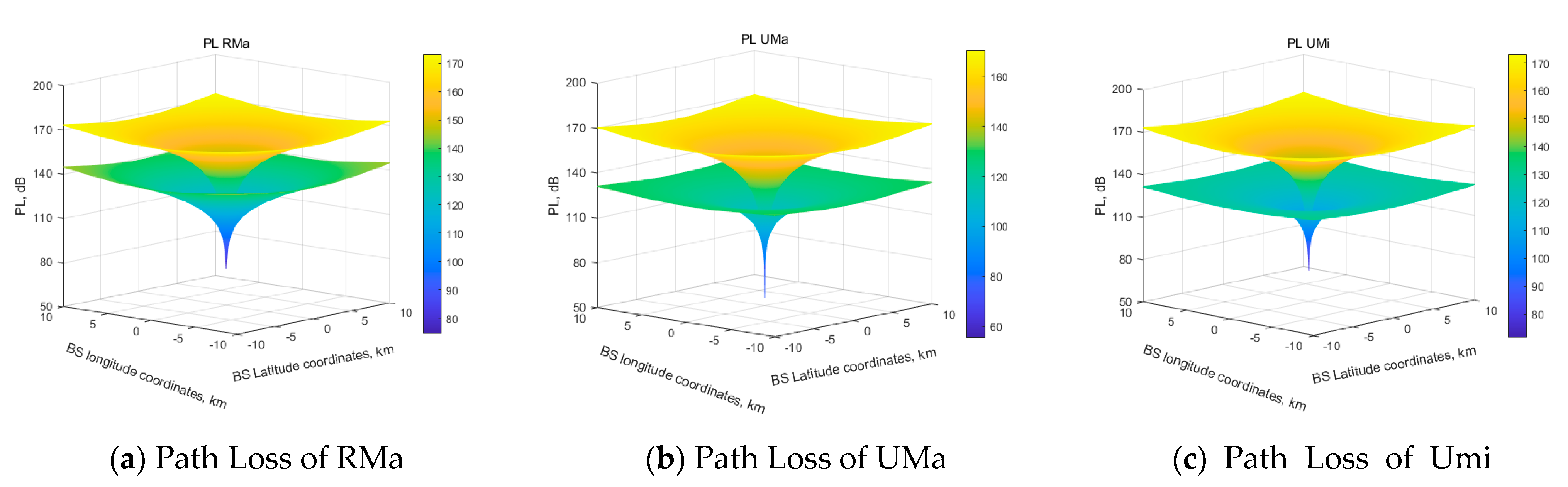
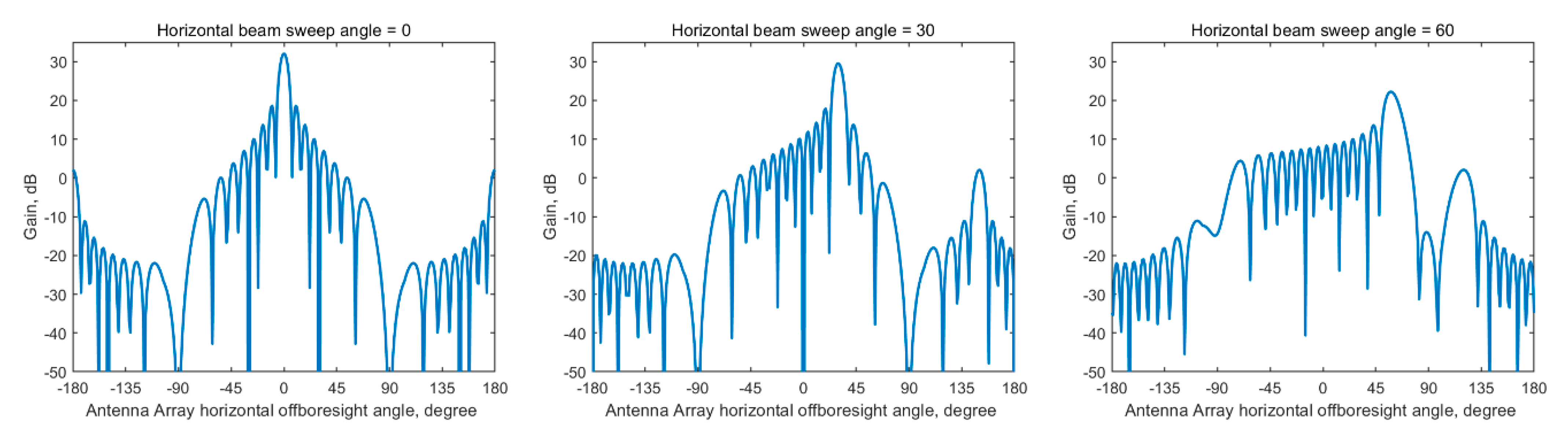
- Using various parameters, provided by the 3GPP and ITU, we show that our proposed method covers all rural macrocell (RMa), urban macrocell (UMa), and urban microcell (UMi) deployment scenarios defined by 3GPP. We further investigate the impact of the antenna pattern defined by the 3GPP omnidirectional antenna and various 5G large-antenna arrays (i.e., 4 × 4, 8 × 8, and 16 × 16).
- We investigate the impact of the ES antenna elevation angle on different protection methods and consider the worst-case scenario for FSS ES protection. We further incorporate the LOS and non-line-of-sight (NLOS) propagation conditions between the BS and ES using the 3GPP LOS probability function.
- We propose a new protection method, which combines the exclusion area and restricted area, where the BSs subjected to Tx power control scheme could be deployed. Moreover, we propose an iterative BS Tx power control scheme. The proposed protection method, using the exclusion area as well as restricted areas, with Tx power control scheme are simulated.
2. Background Knowledge
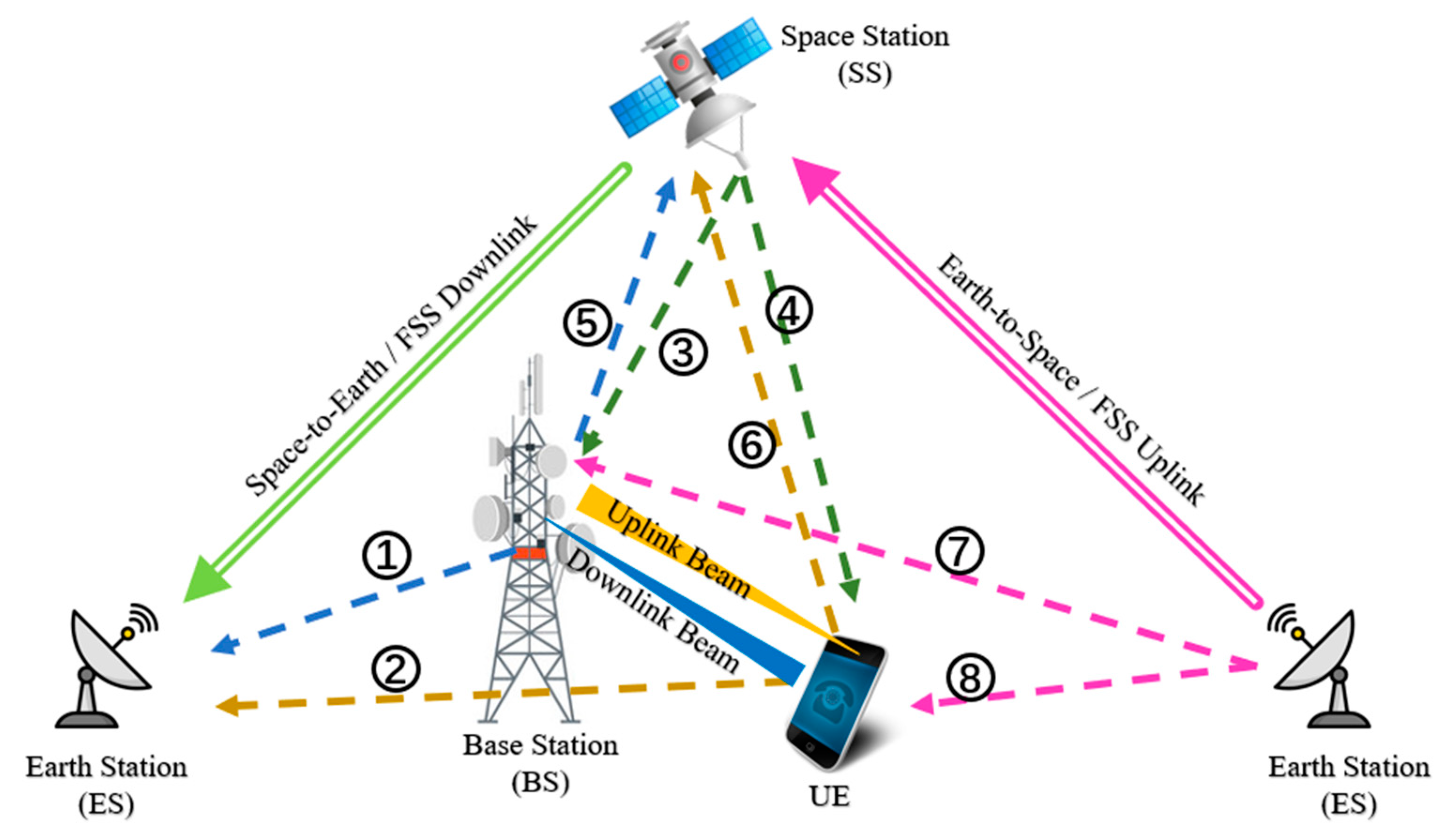
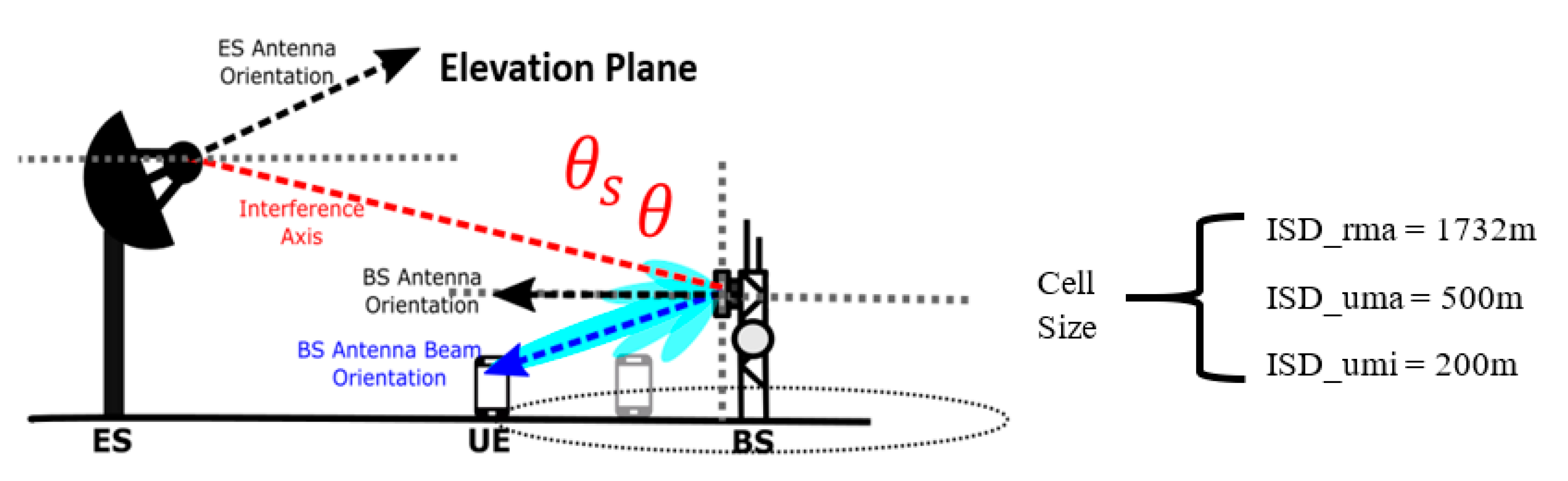
2.1. Basic Scenarios and Parameters
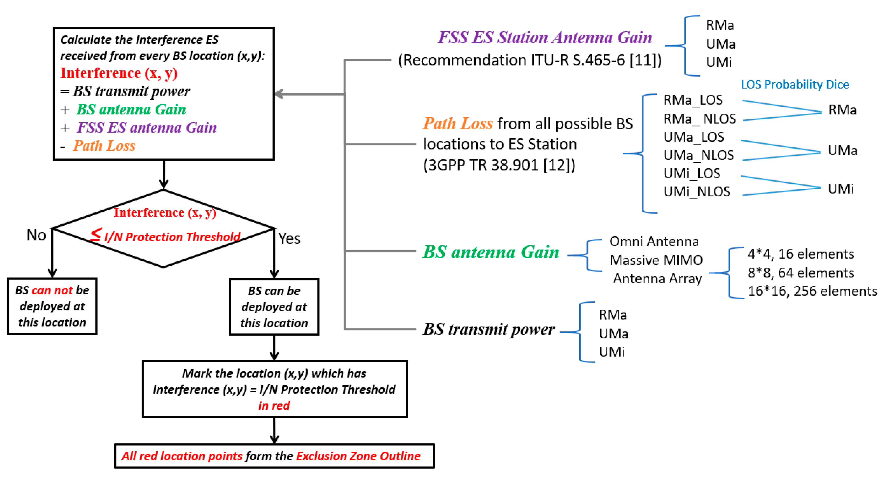
2.2. Interference Derivation
- ES antenna pattern: Recommendation ITU-R S.465-6 [11]
| Algorithm 1 Pseudocode for LOS and NLOS distance functions based on a random mechanism and LOS probability. |
| 1. for each possible BS location (x,y): |
| 2. Calculate the 2-dimensional distance d(x,y) between BS(x,y) and ES(0,0) |
| 3. Calculate the LOS probability PLOS(x,y) according to the model in 3GPP TR 38.901 |
| 4. roll a DiceLOS(x,y), i.e., generate a random number in the range [0, 100] |
| 5. if LOS probability PLOS(x,y) > DiceLOS(x,y), then |
| 6. the propagation condition from BS to ES is LOS |
| 7. else |
| 8. the propagation condition from BS to ES is NLOS |
| 9. end |
| 10. end |
- Horizontal pattern:
- Vertical pattern:
- Single antenna element pattern:where : horizontal 3-dB beamwidth, : front-to-back ratio, vertical 3-dB beamwidth, and : side-lobe level limit. However, a planar uniform rectangular array (URA) antenna pattern uses the procedure illustrated below:
- Array factor:where , , .
- Array pattern:where : main beam steering angle due to beamforming, : correlation coefficient assumed to be equal to unity, : amplitude vector with an equal and fixed amplitude, number of antenna elements in the array, and : vertical and horizontal spacings between the array elements.
3. Distance Protection Methods
3.1. I/N Protection Threshold
- In-band sharing:
- (1)
- I/N = −12.2 dB, corresponding to the total interference received from other systems having co-primary statuses during 100% of the worst month.
- (2)
- I/N = −10 dB, corresponding to the aggregate interference received from the co-primary allocations during 20% of any month.
- Adjacent band sharing:
- (1)
- I/N = −20 dB, corresponding to the aggregate interference received from all other sources during 100% of the time.
3.2. Exclusion Zone
3.3. Restriction Zone and Interactive BS Tx Power Control Scheme
4. Numerical Results
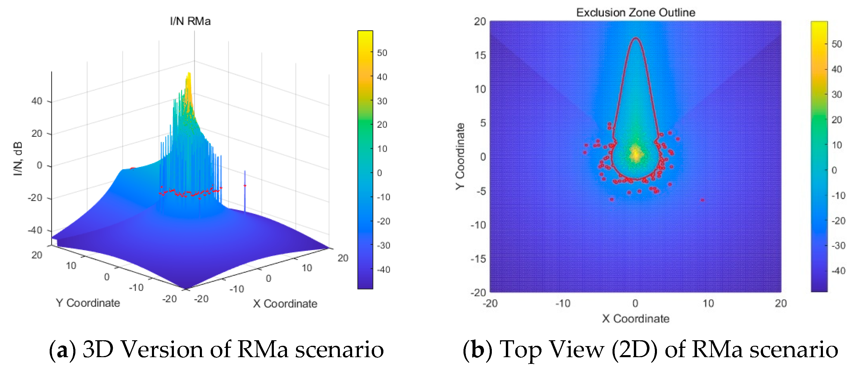
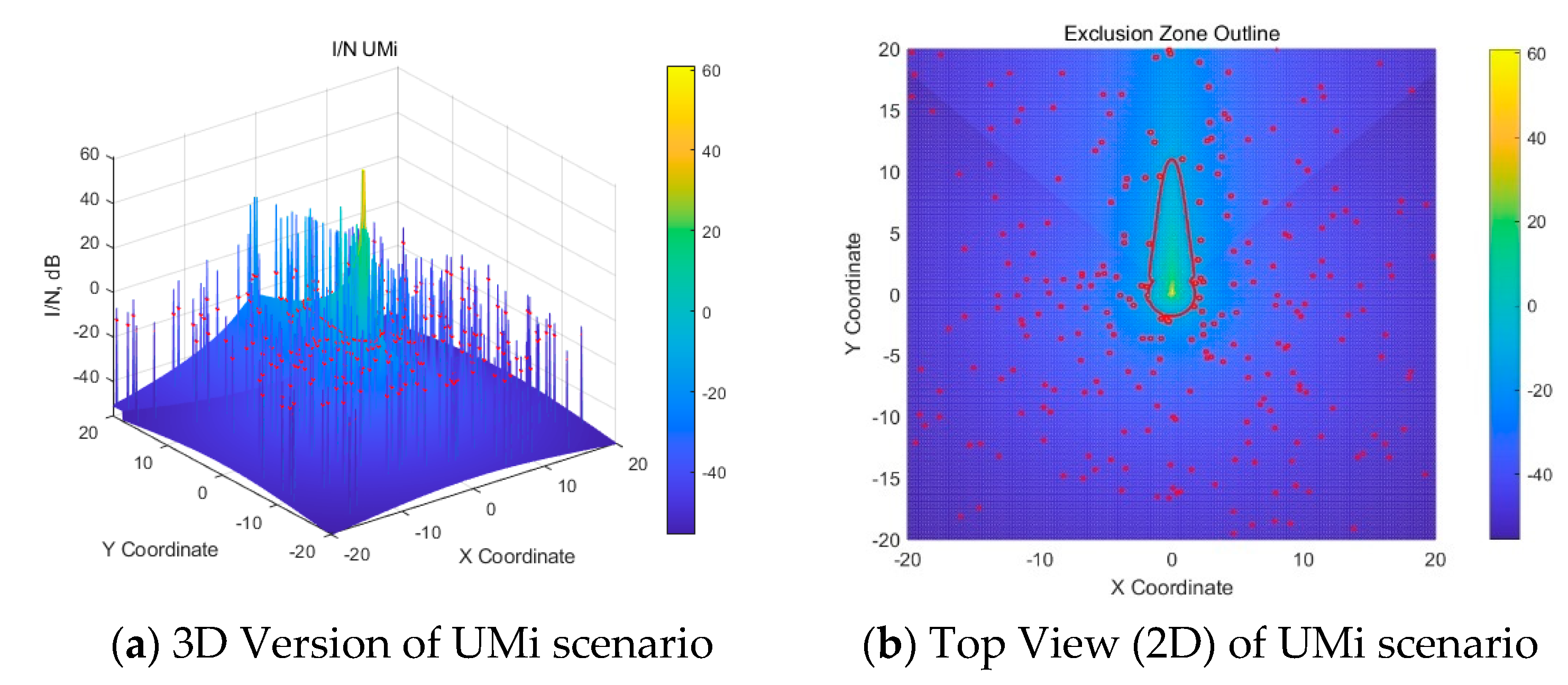
4.1. Exclusion Zone
4.1.1. The Exclusion Zone When Using Omni BS Antenna
4.1.2. The Exclusion Zone When Using Beamforming Antenna Array
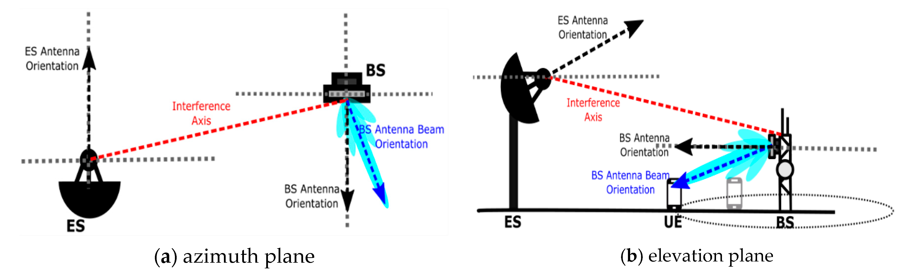
- Azimuth plane:
- Elevation plane:
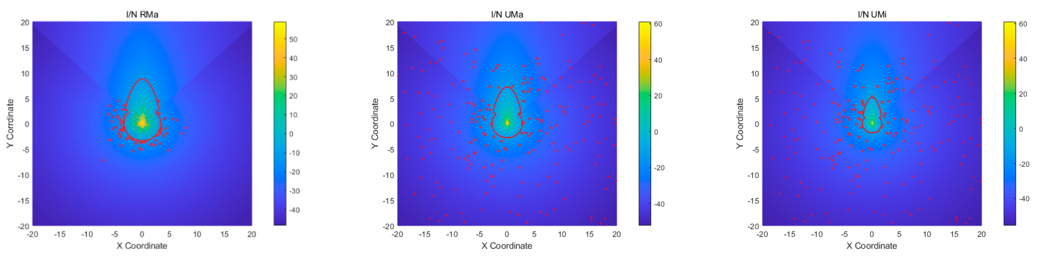
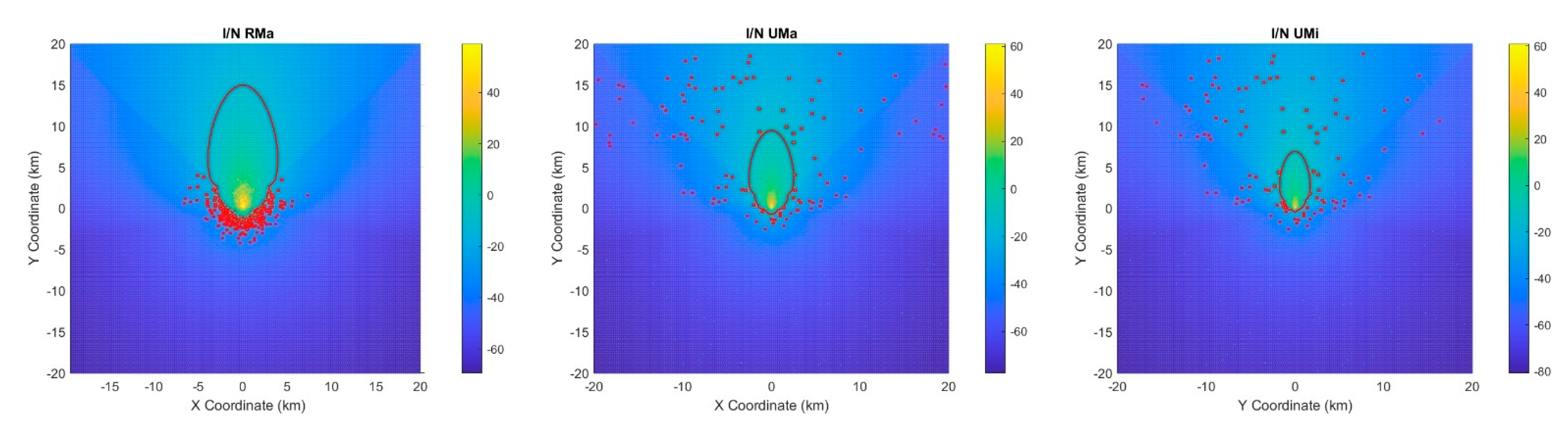
4.1.3. The Effects of ES Elevation Angle on Exclusion Zone
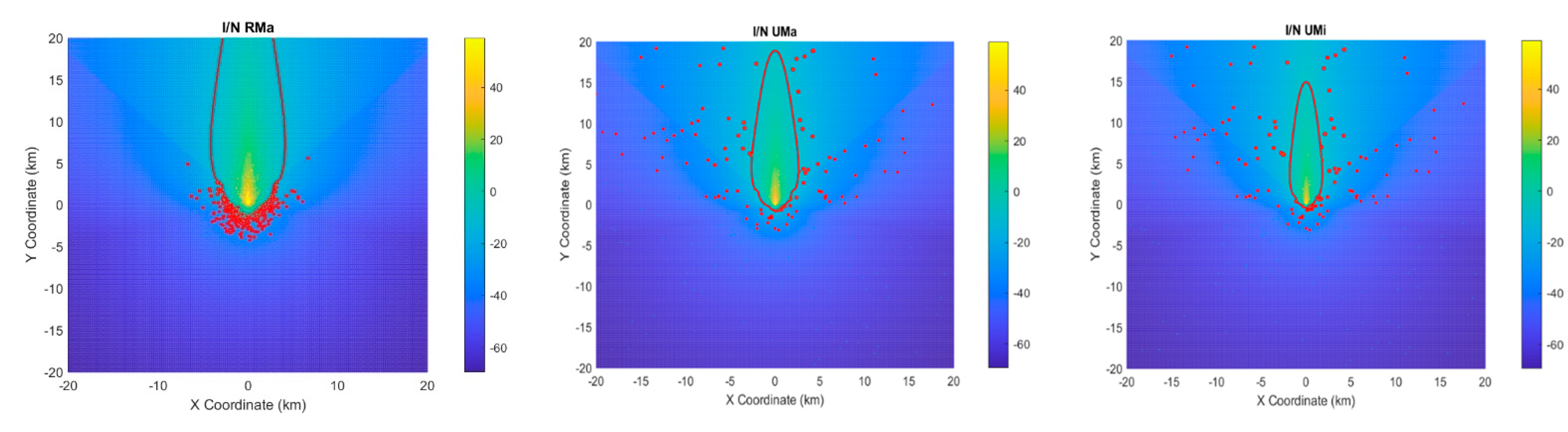
4.2. Restriction Zone
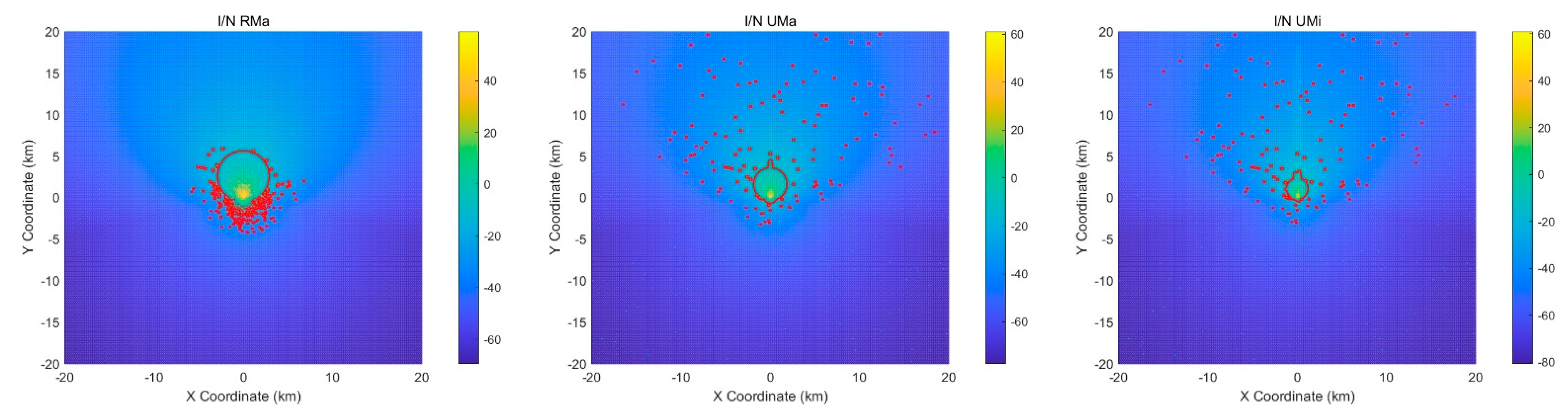
4.2.1. Restriction Zone and BS Tx Power Control (Omni Antenna Results)
- RMa, ISD = 1732 m, in 100 × 100 km area:
- (1)
- About 3337 BSs can be deployed outside the exclusion zone in the RMa
- (2)
- The interference threshold for the restriction zone in the RMa is −47.43 dB
- (3)
- About 998 BSs within the restriction zone require Tx power control in the RMa
- UMa, ISD = 500 m, in 30 × 30 km area:
- (1)
- About 3484 BSs can be deployed outside the exclusion zone in the UMa
- (2)
- The interference threshold for the restriction zone in the UMa is −47.62 dB
- (3)
- About 3484 BSs within the restriction zone require Tx power control in the UMa
- UMi, ISD = 200 m, in 30 × 30 km area:
- (1)
- About 22,061 BSs can be deployed outside the exclusion zone in the UMi
- (2)
- The interference threshold for the restriction zone in the UMi is −55.64 dB
- (3)
- About 22,061 BSs within the restriction zone need Tx power control in the UMi
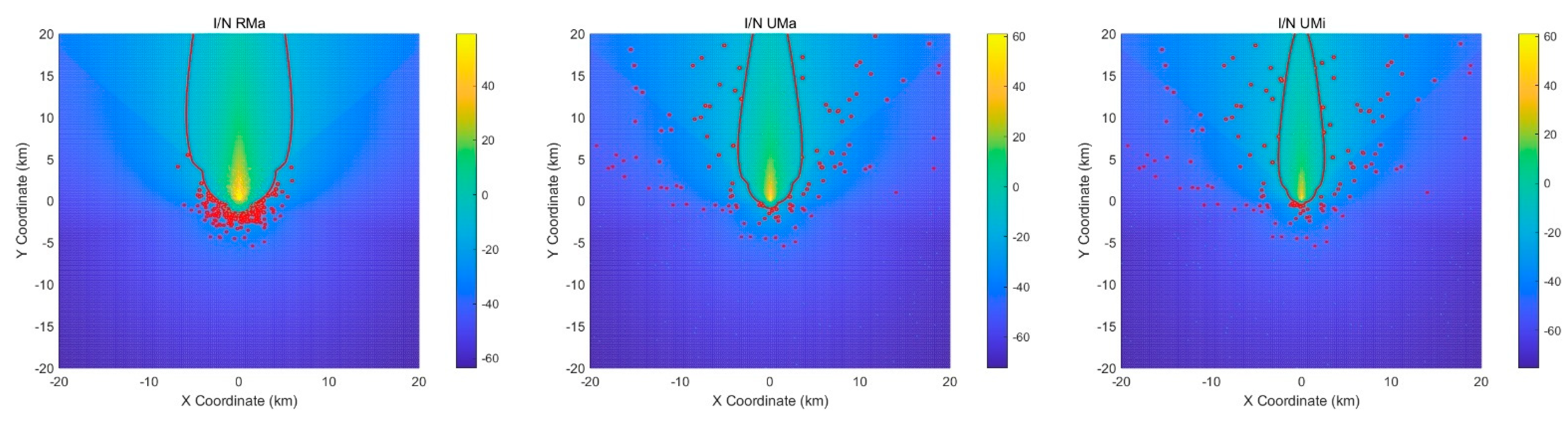
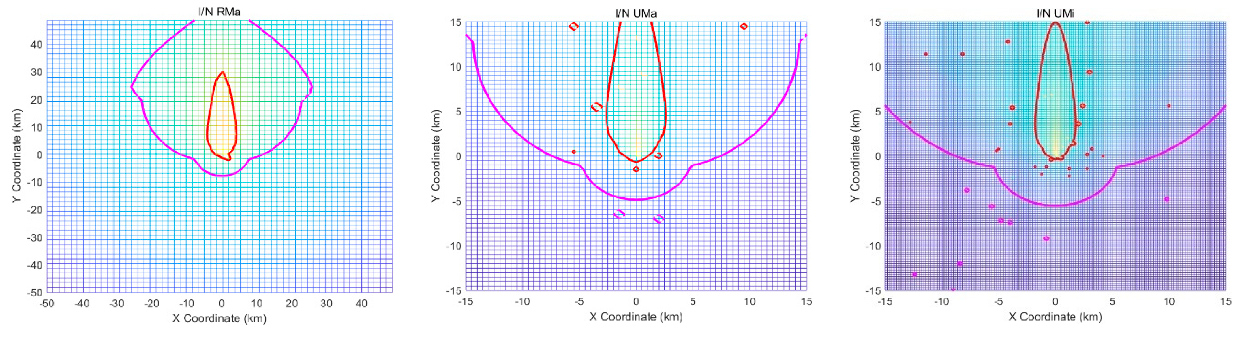
4.2.2. Restriction Zone and BS Tx Power Control for 4 × 4 Antenna Array
- RMa, ISD = 1732 m, in 100 × 100 km area:
- (1)
- About 3320 BSs can be deployed outside the exclusion zone in the RMa
- (2)
- The interference threshold for the restriction zone in the RMa is −47.39 dB
- (3)
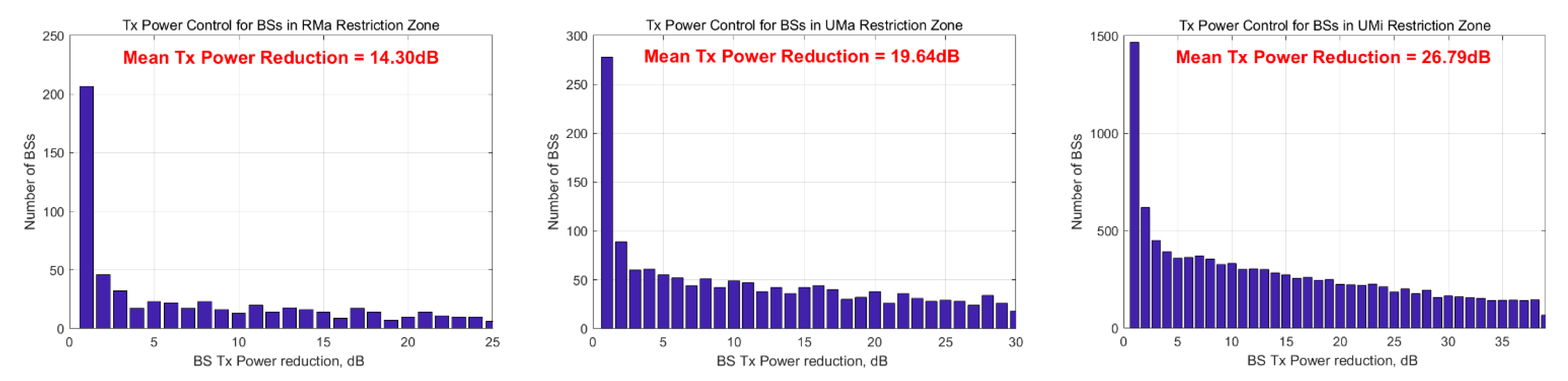
- About 606 BSs within the restriction zone require Tx power control in the RMa
- UMa, ISD = 500 m, in 30 × 30 km area:
- (1)
- About 3463 BSs can be deployed outside the exclusion zone in the UMa
- (2)
- The interference threshold for the restriction zone in the UMa is −47.59 dB
- (3)
- About 1450 BSs within the restriction zone require Tx power control in the UMa
- UMi, ISD = 200 m, in 30 × 30 km area:
- (1)
- About 21,831 BSs can be deployed outside the exclusion zone in UMi
- (2)
- The interference threshold for the restriction zone in the UMi is −55.59 dB
- (3)
- About 10,960 BSs within the restriction zone require Tx power control in the UMi.
- (a)
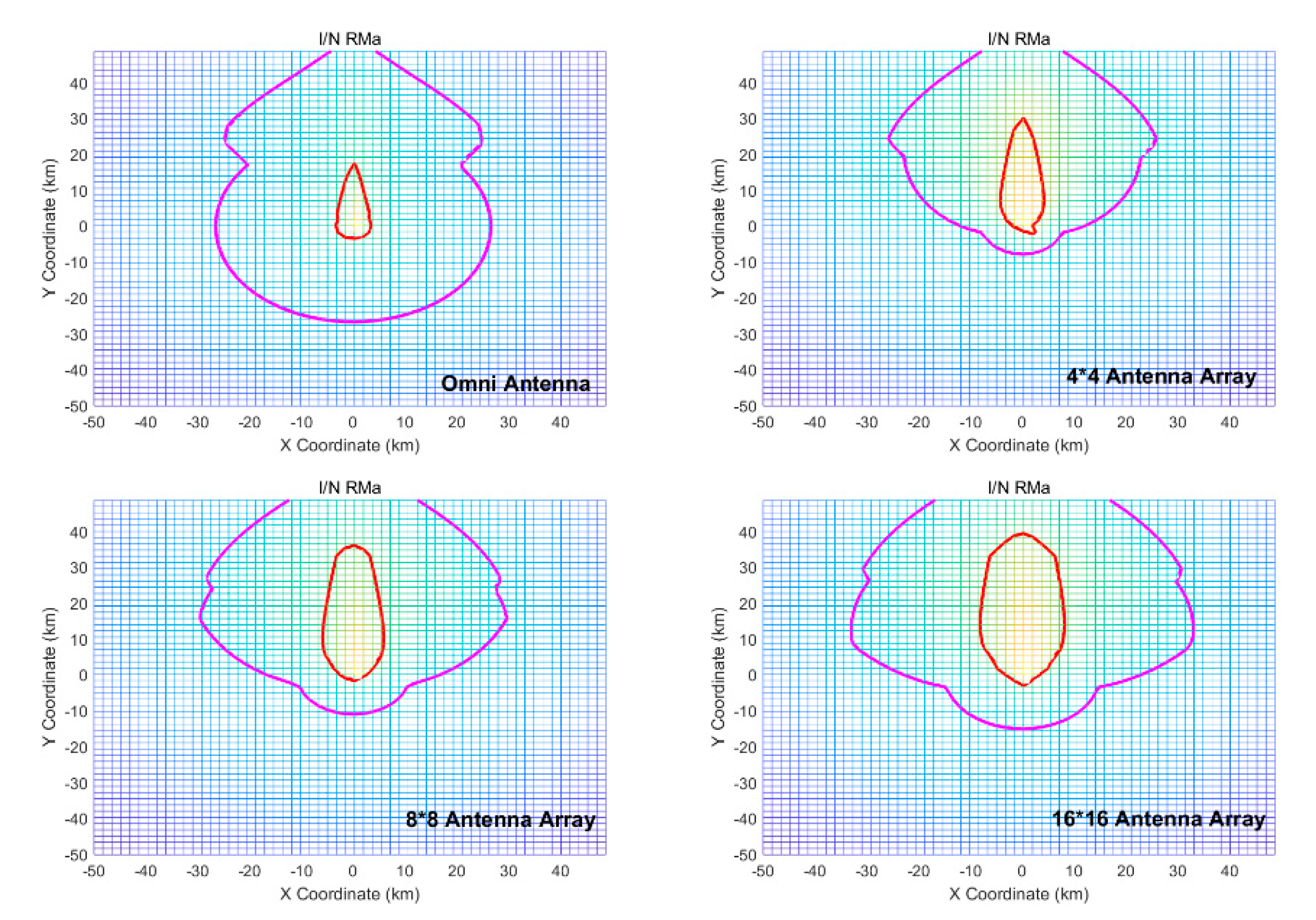
- For the RMa scenario, the array antenna has a higher gain and larger exclusion zone. Although the exclusion zone is larger than that of the omnidirectional antenna, the rear restriction zone of the ES antenna is much smaller. This is because of the directional attenuation of the MIMO antenna array. The larger the number of elements in the array, the larger the exclusion zone. This also results in a larger restriction zone, owing to the higher gain of the antenna array, as shown in Figure 26.
- Because of the larger exclusion zone, the number of BSs that can be deployed continues to decrease with the increasing number of array elements.
- Comparing the omnidirectional antenna and 4 × 4 antenna array, the number, and percentage of BSs that require Tx power control are significantly lower because of the drastic shrinkage of the restriction zone. However, owing to the higher antenna gain, the mean Tx power reduction is higher for the case of BSs with a 4 × 4 antenna array.
- By increasing the number of antenna elements, the number and percentage of BSs requiring Tx power control also increase, owing to the expanded restriction zone.
- By increasing the number of antenna elements, the maximum Tx power and mean Tx power reduction increase, owing to the higher antenna gain.
- (b)
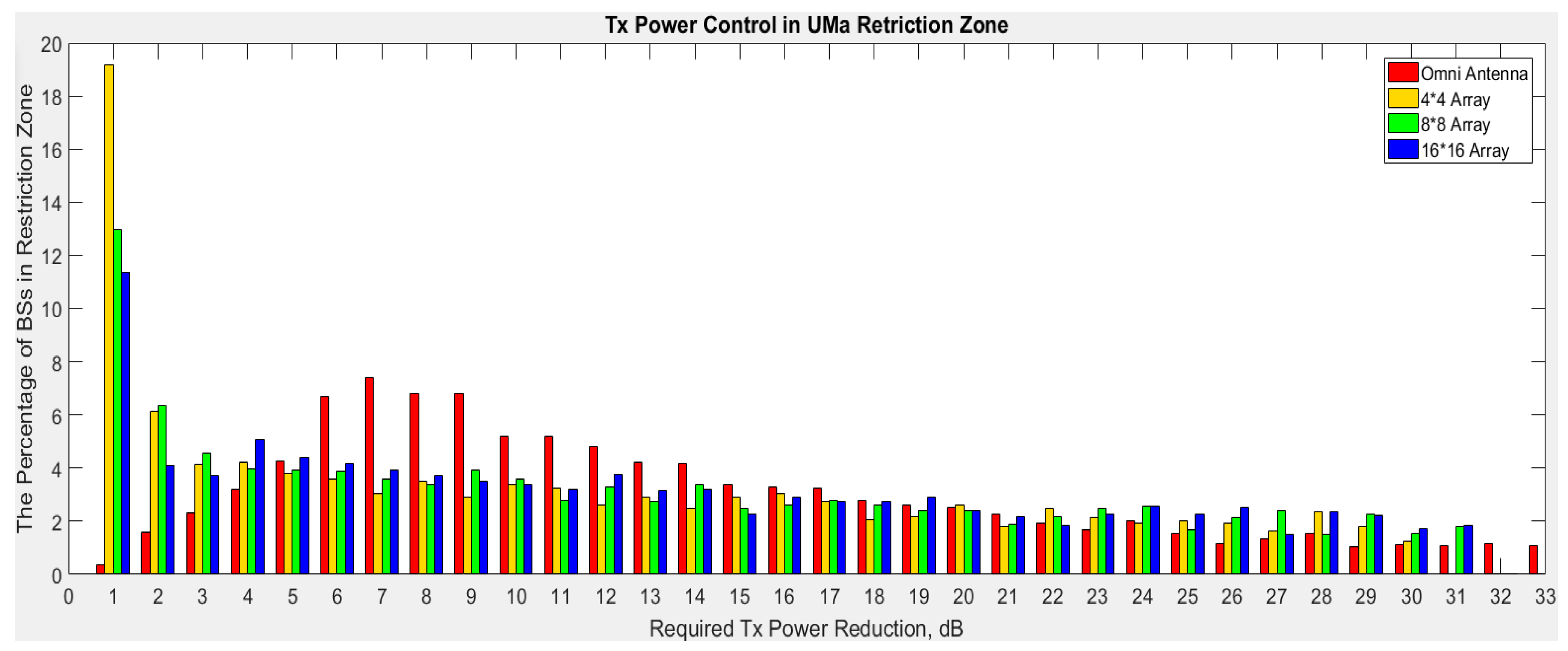
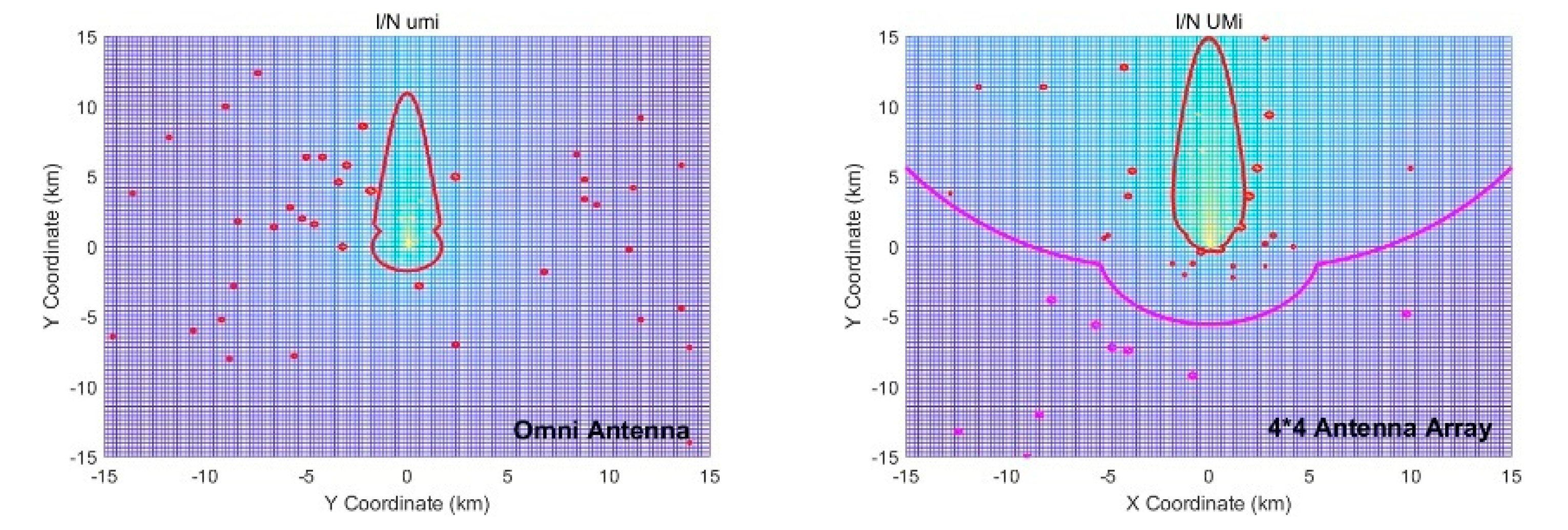
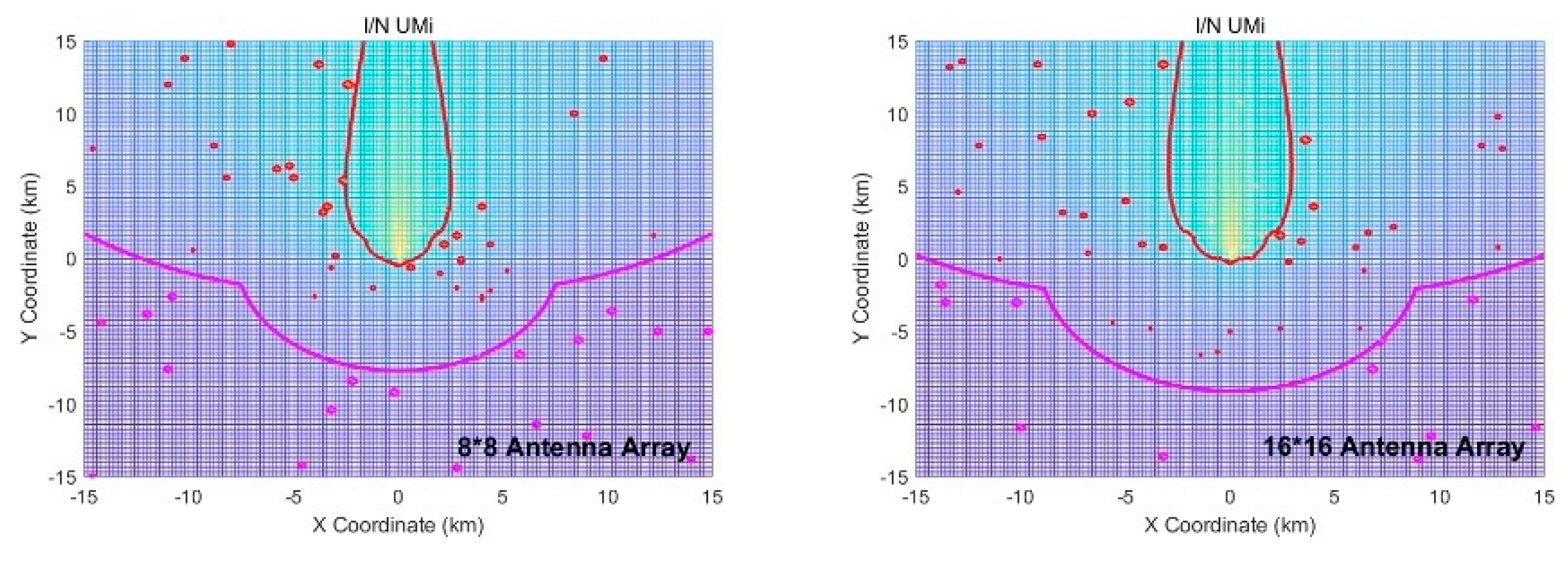
- For the UMa, the array antenna has a higher gain, thus causing a larger exclusion zone. Although the exclusion zone is larger than that of the omnidirectional antenna, the restriction zone at the backside of the ES antenna is much smaller. This is owed to the directional attenuation of the MIMO antenna array. As there are larger numbers of elements in the arrays, the exclusion and restriction zones are larger because of the higher antenna array gains, as shown in Figure 28.
- (c)
- For the UMi scenario, the array antenna has a higher gain, which results in a larger exclusion zone. Although the exclusion zone is larger than that of the omnidirectional antenna, the restriction zone at the rear of the ES antenna is much smaller. This is owed to the directional attenuation of the MIMO antenna array. Note that there are a larger number of elements in the array; therefore, the exclusion and restriction zones are larger because of the higher gain of the antenna array, as shown in Figure 30.
5. Conclusions
Author Contributions
Funding
Conflicts of Interest
References
- Anisimoff. 5G Bands in South Korea. Available online: http://anisimoff.org/eng/5g/spectrum/5g_south_korea.html (accessed on 13 May 2021).
- Hattab, G.; Moorut, P.; Visotsky, E.; Cudak, M.; Ghosh, A. Interference Analysis of the Coexistence of 5G Cellular Networks with Satellite Earth Stations in 3.7–4.2 GHz. In Proceedings of the 2018 IEEE International Conference on Communications Workshops (ICC Workshops), Kansas City, MO, USA, 20–24 May 2018; Institute of Electrical and Electronics Engineers (IEEE): Piscataway, NJ, USA, 2018; pp. 1–6. [Google Scholar]
- Guidolin, F.; Nekovee, M.; Badia, L.; Zorzi, M. A Study on the Coexistence of Fixed Satellite Service and Cellular Networks in a mmWave Scenario; Institute of Electrical and Electronics Engineers (IEEE): Piscataway, NJ, USA, 2015; pp. 2444–2449. [Google Scholar]
- ITU Radio Regulations, Section IV. Radio Stations and Systems. Available online: https://www.itu.int/dms_pub/itu-r/md/15/wrs18/sp/R15-WRS18-SP-0003!!PDF-E.pdf (accessed on 13 May 2021).
- ETRI Metis Project. Intermediate Description of the Spectrum Needs and Usage Principles. D5.1 Deliverable, August 2013. Available online: https://metis2020.com/wp-content/uploads/deliverables/METIS_D5.1_v1.pdf (accessed on 13 May 2021).
- Sun, Q.; Nan, S. Coexistence Studies between LTE-Hotspot Indoor and Earth Station of Fixed Satellite Service in the Band 34003600MHz. In Proceedings of the 2012 IEEE 11th International Conference on Signal Processing, Beijing, China, 21–25 October 2012; Institute of Electrical and Electronics Engineers (IEEE): Piscataway, NJ, USA, 2012; Volume 3, pp. 2275–2278. [Google Scholar]
- Su, C.; Han, X.; Yan, X.; Zhang, Q.; Feng, Z. Coexistence Analysis between IMT-Advanced System and Fixed Satellite Service System; Institute of Electrical and Electronics Engineers (IEEE): Piscataway, NJ, USA, 2014; pp. 1692–1697. [Google Scholar]
- Kim, S.; Visotsky, E.; Moorut, P.; Bechta, K.; Ghosh, A.; Dietrich, C. Coexistence of 5G With the Incumbents in the 28 and 70 GHz Bands. IEEE J. Sel. Areas Commun. 2017, 35, 1254–1268. [Google Scholar] [CrossRef]
- Guidolin, F.; Nekovee, M. Investigating Spectrum Sharing between 5G Millimeter Wave Networks and Fixed Satellite Systems. In Proceedings of the 2015 IEEE Globecom Workshops (GC Wkshps), San Diego, CA, USA, 6–10 December 2015; IEEE: Piscataway, NJ, USA, 2015; pp. 1–7. [Google Scholar]
- CEPT ECC Report 254. Operational Guidelines for Spectrum Sharing to Support the Implementation of the Current ECC Framework in the 3600–3800 MHz Range. Available online: https://docdb.cept.org/document/958 (accessed on 13 May 2021).
- ITU-R Recommendation S.465-6. Reference Radiation Pattern of Earth Station Antennas in the Fixed-Satellite Service for Use in Coordination and Interference Assessment in the Frequency Range from 2 to 31 GHz. 2010. Available online: https://iopscience.iop.org/article/10.1088/1742-6596/1169/1/012054/pdf (accessed on 13 May 2021).
- Karimi, H.R.; Casagni, A.; Gulyaev, A. Spectrum Sharing between the Mobile Service and Existing Fixed and Fixed Satellite Services in the 3.6–3.8 GHz Band. In Proceedings of the 2015 IEEE International Symposium on Dynamic Spectrum Access Networks (DySPAN), Stockholm, Sweden, 29 September–2 October 2018; Institute of Electrical and Electronics Engineers (IEEE): Piscataway, NJ, USA, 2015; pp. 142–153. [Google Scholar]
- ITU-R Report S.2368-0. Sharing Studies between International Mobile Telecommunication-Advanced Systems and Geostationary Satellite Networks in the Fixed-Satellite Service in the 3400–4200 MHz and 4500–4800 MHz Frequency Bands in the WRC Study Cycle Leading to WRC-15. 2015. Available online: https://www.itu.int/pub/R-REP-S.2368 (accessed on 13 May 2021).
- 3GPP. Study on Channel Model for Frequencies from 0.5 to 100 GHz (Release 15). 3GPP TR 38.901 V15.0.0. 2018. Available online: https://www.etsi.org/deliver/etsi_tr/138900_138999/138901/14.00.00_60/tr_138901v140000p.pdf (accessed on 13 May 2021).
- ITU-R P.452-15. Prediction Procedure for the Evaluation of Interference between Stations on the Surface of the Earth at Frequencies above about 0.1 GHz. 2013. Available online: https://www.itu.int/rec/R-REC-P.452/en (accessed on 13 May 2021).
- 3GPP. Radio Frequency (RF) System Scenarios (Release 15). 3GPP TR 36.942 V15.0.0. 2018. Available online: https://portal.3gpp.org/desktopmodules/Specifications/SpecificationDetails.aspx?specificationId=2592 (accessed on 13 May 2021).
- 3GPP. Evolved Universal Terrestrial Radio Access (E-UTRA): Base Station (BS) Radio Transmission and Reception (Release 15). 3GPP TS 36.104 V15.0.0. 2018. Available online: https://portal.3gpp.org/desktopmodules/Specifications/SpecificationDetails.aspx?specificationId=2412 (accessed on 13 May 2021).
- 3GPP. NR: Base Station (BS) Radio Transmission and Reception (Release 15). 3GPP TS 38.104 V15.3.0. 2018. Available online: https://www.lp-ats.com/smart-pcb-stacking?https://www.lp-ats.com/smart-pcb-stacking%3Futm_source%3DGoogle%26utm_medium%3Dads%26utm_campaign%3D12766553251%26utm_term%3D515054125127&gclid=EAIaIQobChMI-cXkj42e8QIVA3ZgCh05XQiKEAAYASAAEgKc-PD_BwE (accessed on 13 May 2021).
- 3GPP. Study of Radio Frequency (RF) and Electromagnetic Compatibility (EMC) Requirements for Active Antenna Array sys-tem (AAAS) Base Station (Release 12). 3GPP TR 37.840 V12.1.0. 2013. Available online: https://www.mvg-world.com/en/products/emc/emc-antennas/emc-dual-ridge-horn-antenna-eh022?gclid=EAIaIQobChMI8KaWro2e8QIVhnZgCh1cnQN8EAAYASAAEgKuCvD_BwE (accessed on 13 May 2021).
- Tang, P.; Zhang, J.; Molisch, A.F.; Smith, P.J.; Shafi, M.; Tian, L. Estimation of the K-Factor for Temporal Fading from Single-Snapshot Wideband Measurements. IEEE Trans. Veh. Technol. 2019, 68, 49–63. [Google Scholar] [CrossRef]
- 3GPP. Study on 3D Channel Model for LTE (Release 12). 3GPP TR 36.873 V12.7.0. 2018. Available online: https://portal.3gpp.org/desktopmodules/Specifications/SpecificationDetails.aspx?specificationId=2574 (accessed on 13 May 2021).
- ITU-R M.2135. Technical Characteristics of Autonomous Maritime Radio Devices Operating in the Frequency Band 156–162.05 MHz. 2019. Available online: https://www.itu.int/rec/R-REC-M.2135/en (accessed on 13 May 2021).


| Our Work | [2] | [3] | [6] | [7] | [8] | [9] | [12] | ||
|---|---|---|---|---|---|---|---|---|---|
| Protection schemes studied | Exclusion Zone | o | o | o | o | ||||
| Restriction Zone | o | o | o | o | o | o | |||
| Restriction Zone with Pover Control Scheme | o | ||||||||
| Combination of Exclusion Zone & Exclusion Zone | o | ||||||||
| Deployment scenarios considered | Rma | o | o | o | |||||
| Uma | o | o | o | ||||||
| Umi | o | o | o | ||||||
| The effect of different ES Antenna elevation angle | o | ||||||||
| Antenna types studied | Omni | o | o | o | o | o | |||
| 4 × 4 | o | o | o | ||||||
| 8 × 8 | o | o | o | o | |||||
| 16 × 16 | o | o | o | ||||||
| RMa | UMa | UMi | RMa | UMa | UMi | ||
|---|---|---|---|---|---|---|---|
| ES antenna diameter (m) | 10 | 2.4 | 2.4 | Thermal noise (dBm/Hz) | −179 | ||
| ES antenna pattern | Recommendation ITU-R S.465-6 | ES bandwidth (MHz) | 36 | ||||
| ES antenna height (m) | 7 | 30 | 30 | ES antenna maximum gain (dBm) | 56 | ||
| ES antenna elevation angle (degrees) | 5°, 15°, 48°/27.5° mean value | ES antenna adjacent channel sensitivity (ACS) model | Recommendation ITU-R S.465-6 | ||||
| ES receiving system noise temperature (K) | 100 | Effective Earth radius (m) | 8.5 × 10⁶ | ||||
| RMa | UMa | UMi | RMa | UMa | UMi | |||
|---|---|---|---|---|---|---|---|---|
| BS antenna height (m) | 35 | 25 | 10 | BS channel bandwidth (MHz) | 20 | |||
| UE height (m) | 1.5 | 1.5 | 1.5 | Effective environment height (m) | 1 | None | None | |
| Inter-site distance, ISD (m) | 1732 | 500 | 200 | Average building height (m) | 5 | None | None | |
| BS maximum Tx power (dBm) | 46 | 38 | 38 | Average street width (m) | 20 | None | None | |
| BS antenna Tx gain (dB) | Omni antenna | 15 | 15 | 15 | LOS shadow fading (dB) | 6 | 4 | 4 |
| Single antenna element in MIMO antenna array | 8 | 8 | 8 | NLOS shadow fading (dB) | 8 | 6 | 7.82 | |
| BS minimum coupling loss (dB) | 80 | 70 | 70 | |||||
| Antenna Type | Total # of BSs That Can Be Deployed | Interference Threshold for Restriction Zone | Number of BSs in the Restriction Zone | % of Deployed BSs That Require Tx Power Control | Mean Tx Power Reduction in the Restriction Zone |
|---|---|---|---|---|---|
| Omni | 3337 | −47.43 dB | 998 | 29.91 | 13.18 dB |
| 4 × 4 Array | 3302 | −47.39 dB | 606 | 18.35 | 14.30 dB |
| 8 × 8 Array | 3252 | −47.32 dB | 746 | 22.93 | 15.84 dB |
| 16 × 16 Array | 3194 | −47.24 dB | 886 | 27.74 | 17.51 dB |
| Antenna Type | Total # of BSs That Can Be Deployed | Interference Threshold for Restriction Zone | Number of BSs in the Restriction Zone | % of Deployed BSs That Require Tx Power Control | Mean Tx Power Reduction in the Restriction Zone |
|---|---|---|---|---|---|
| Omni | 3484 | −47.62 dB | 3484 | 100 | 27.05 dB |
| 4 × 4 Array | 3463 | −47.59 dB | 1450 | 41.87 | 19.64 dB |
| 8 × 8 Array | 3352 | −47.45 dB | 1682 | 50.18 | 20.84 dB |
| 16 × 16 Array | 3300 | −47.39 dB | 1749 | 53.00 | 21.07 dB |
| Antenna Type | Total # of BSs That Can Be Deployed | Interference Threshold for Restriction Zone | Number of BSs in the Restriction Zone | % of Deployed BSs That Require Tx Power Control | Mean Tx Power Reduction in the Restriction Zone |
|---|---|---|---|---|---|
| Omni | 22,061 | −55.63 dB | 22,061 | 100 | 27.05 dB |
| 4 × 4 Array | 21,831 | −55.59 dB | 10,960 | 50.20 | 26.79 dB |
| 8 × 8 Array | 21,193 | −55.46 dB | 12,218 | 57.65 | 27.78 dB |
| 16 × 16 Array | 20,855 | −55.39 dB | 13,010 | 62.38 | 28.35 dB |
Publisher’s Note: MDPI stays neutral with regard to jurisdictional claims in published maps and institutional affiliations. |
© 2021 by the authors. Licensee MDPI, Basel, Switzerland. This article is an open access article distributed under the terms and conditions of the Creative Commons Attribution (CC BY) license (https://creativecommons.org/licenses/by/4.0/).
Share and Cite
Wei, Y.; Liu, S.; Hwang, S.-H. Distance Protection for Coexistence of 5G Base Station and Satellite Earth Station. Electronics 2021, 10, 1481. https://doi.org/10.3390/electronics10121481
Wei Y, Liu S, Hwang S-H. Distance Protection for Coexistence of 5G Base Station and Satellite Earth Station. Electronics. 2021; 10(12):1481. https://doi.org/10.3390/electronics10121481
Chicago/Turabian StyleWei, Yiqiao, Shuzhi Liu, and Seung-Hoon Hwang. 2021. "Distance Protection for Coexistence of 5G Base Station and Satellite Earth Station" Electronics 10, no. 12: 1481. https://doi.org/10.3390/electronics10121481
APA StyleWei, Y., Liu, S., & Hwang, S.-H. (2021). Distance Protection for Coexistence of 5G Base Station and Satellite Earth Station. Electronics, 10(12), 1481. https://doi.org/10.3390/electronics10121481