Article

Interference Signal Identification of Sensor Array Based on Convolutional Neural Network and FPGA Implementation

1
Institute of Microelectronics of Chinese Academy of Sciences, Beijing 100029, China
2
University of Chinese Academy of Sciences, Beijing 100049, China
3
Beijing Key Laboratory for Next Generation RF Communication Chip Technology, Beijing 100029, China
*
Author to whom correspondence should be addressed.
Electronics 2021, 10(22), 2867; https://doi.org/10.3390/electronics10222867
Submission received: 14 October 2021 / Revised: 14 November 2021 / Accepted: 16 November 2021 / Published: 21 November 2021
(This article belongs to the Special Issue Recent FPGA Architectures and Applications)

Abstract

:
The pulse carries important physiological and pathological information about the human body. The piezoresistive sensor used to capture vascular pulsation information has transitioned from a single-point to a sensor array. However, the interference signal between channels has become a key bottleneck restricting the development of the sensor array pulse diagnosis equipment. The sensor in contact with vascular pulsation obtains the pulse signal. When some sensors are displaced due to vascular pulsation, other sensors will be driven to move, which will produce interference signals. Signal interference is a common problem for sensor arrays, but few people have analyzed this problem from the perspective of the algorithm. In this paper, an interference signal recognition algorithm of the sensor array based on a convolutional neural network (CNN) is proposed. Firstly, a simple mechanical structure model was established to analyze the generation mechanism of interference signals in one MEMS sensor array acquisition system. Then, a CNN model with fewer parameters was designed for identifying interference signals. Finally, the CNN model was implemented on a field-programmable gate array (FPGA). The results show that the CNN algorithm could identify interference signals well, and the accuracy of the algorithm was 99.3%. The power consumption of the CNN accelerator was 0.673 W at a working frequency of 100 MHz. The interference signal identification algorithm is proposed to ensure the accurate analysis of array signals. FPGA implementation lays the foundation for the miniaturization and portability of the equipment.

1. Introduction

The combination of Chinese and Western medical treatments is a characteristic of Chinese fight against the new coronary pneumonia, and it has received good results. Chinese medicine, with its several thousand years history, has attracted increasing attention. A pulse wave is produced by the regular contraction and the relaxation of the heart and contains a wealth of physiological information about the body [1]. Doctors can detect pathological changes in various organs in the human body by touching the pulse. Pulse diagnosis is an important method in Chinese medicine and Ayurveda in India [2,3]. Doctors can detect the pulse strength, width, length, and frequency of the blood vessel through their fingers, and analyze a patient’s physical state. However, this method lacks one quantifiable standard [4,5]. Objective research on pulse diagnosis has emerged at home and abroad. A single-point sensor, such as a piezoelectric sensor [6], piezoresistive sensor [7], infrared sensor [8], or ultrasonic sensor [9,10], was used in early pulse wave acquisition equipment.
Because the piezoresistive sensor and piezoelectric sensor can simulate the finger feeling of traditional Chinese medicine doctors, they occupy a mainstream position in pulse diagnostic instruments. However, early single-point sensors could not measure the pulse width or pulse length. Sensor arrays can measure the information of a blood vessel more fully; vascular pulsation will produce a three-dimensional topographic map on the sensor array. By measuring the width and length information on the three-dimensional topographic map, the indirect measurement of pulse width and pulse length can be realized [11,12]. Therefore, sensor arrays have become the focus of current research.
Ki Young Shin et al. developed a sensor array module containing seven piezoresistive sensors, through which the position of the radial artery can be determined [13]. Peng et al. proposed a multi-channel pulse wave signal acquisition system with 12 pressure sensors arranged in a row to measure the width of the radial artery [12]. Wang et al. designed a pulse signal acquisition system of a photoelectric sensor array, using nine photoelectric sensors to detect spatial information to locate the pulse center [14]. The introduction of the sensor array could obtain more abundant pulse information, and provide an important basis for the clinical diagnosis and treatment of diseases [15,16]. However, the problem of signal interference has become a key bottleneck restricting the development of sensor array pulse diagnosis equipment.
The sensor in contact with vascular pulsation obtains the pulse signal. When some sensors are displaced due to vascular pulsation, other sensors are driven to move, which produces interference signals. Matti Kaisti et al. designed a three-channel pulse wave acquisition system [17]. Three MEMS pressure sensors are assembled in a triangular shape on a flexible wristband for pulse detection of the radial artery. The three sensors are directly connected by a rigid structure. When a sensor touches the vibration point of the radial artery, it produces displacement. The displacement of the sensor drives the displacement of the rigid structure. The displacement of the rigid structure changes the pressure on the other sensors, and the signals of other sensors are disturbed. Chen et al. developed a radial artery pulse acquisition system based on a dense pressure sensor array worn on the fingers [18]. Eighteen ultra-small MEMS pressure sensors are integrated on a flexible printed circuit board (FPC). These eighteen sensors are also physically connected, and the interference phenomena appeared. The most obvious manifestation of this interference is a kind of interference wave that is axisymmetric with the pulse wave. The problem of array signal interference is common, but few people have analyzed this problem.
In classification, machine learning and deep learning methods based on statistical recognition have been widely studied. Compared with other classification algorithms, convolutional neural networks (CNNs) have a higher accuracy [19]. This paper proposes a sensor array interference signal recognition algorithm based on a CNN. This work makes the following contributions:
i.
We established a simple mechanical structure model to analyze the generation mechanism of interference signals in the MEMS sensor array acquisition system;
ii.
We designed a CNN model with fewer parameters to identify the interference wave;
iii.
We implemented the CNN model a on field-programmable gate array (FPGA).
The completion of this work provides help to obtain information, such as pulse width and pulse length, from the array sensor, which may help doctors better understand the patient’s physical condition.

2. Materials and Methods

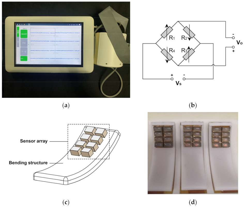
2.1. MEMS Sensor Array Acquisition System

This paper uses a MEMS sensor array acquisition system, as shown in Figure 1a [20]. The sensor array is an important module of the system. The sensor array module was composed of three components: the sensor array, the inflatable airbag and the bending structure. The MEMS pressure sensor chip (MPS20N0100D, MEMStek Co., Ltd., Wuxi City, Jiangsu Province, China) was selected as the sensitive element. The circuit structure diagram of the sensor chip is shown in Figure 1b. Four identical piezoelectric resistors, R1–R4, form a Wheatstone bridge. When the sensor is subjected to an external force, the resistance of the four resistance strain gauges will change, the balance of the original Wheatstone bridge circuit will be broken, and the bridge will output a voltage signal proportional to the pressure. The schematic diagram of the MEMS sensor array is shown in Figure 1c; Figure 1d is a physical diagram. The MEMS pressure sensor was composed of 8 MEMS sensors arranged in 4 rows and 2 columns. The sensor contact material was food-grade silica gel, which has good biocompatibility and will not cause damage to the wrist after collection. In order to ensure sufficient contact between the acquisition module and the skin of the wrist, the bending structure was designed to be curved. The acquisition used airbag pressurization to make the sensor array exert pressure on the subject’s wrist.
The system can provide a static pressure of 0–210 mmHg during the acquisition process; the pressure applied to the wrist of the subject was increased in steps of 10 mmHg, and the pressure of each step was maintained for about 15 s to obtain a set of stable pulse signals. After completing the entire collection process, the airbag was deflated.

2.2. Mechanical Analysis of Interference Signals

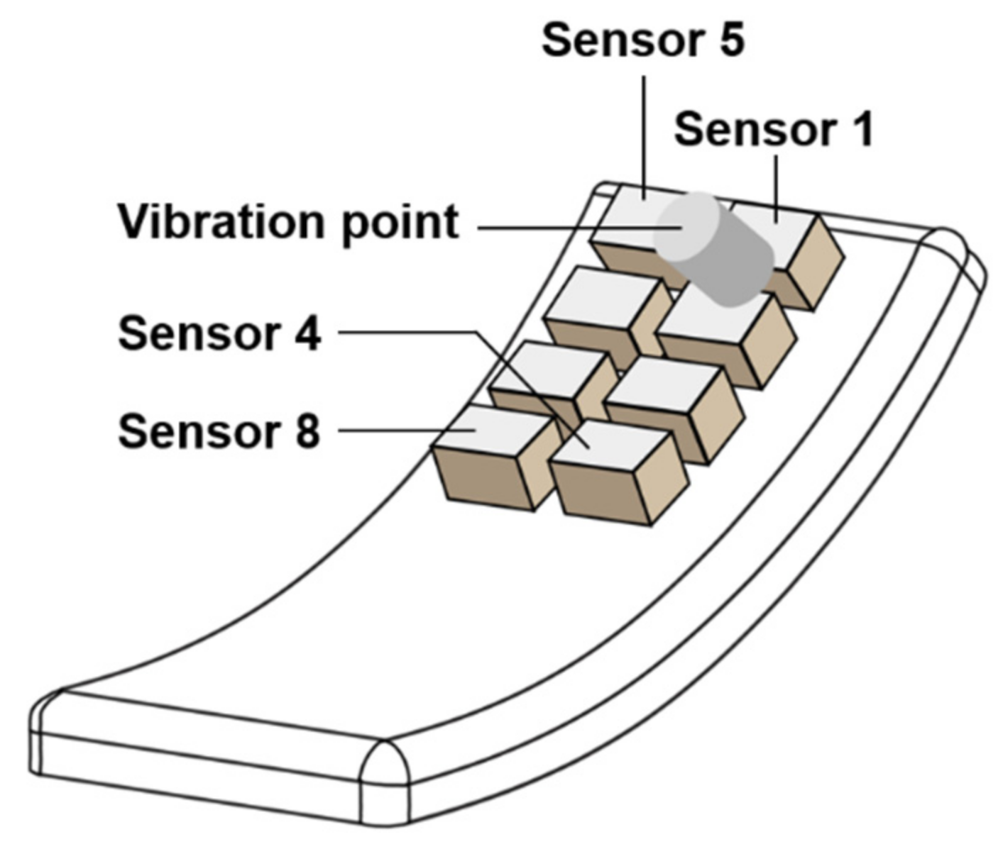
2.2.1. Single-Point Vibration Signal Generator

This paper presents the design of a single-point vibration signal generator to study the generation mechanism of interference signals in the sensor array. The structure of the generator is shown in Figure 2a, which is mainly composed of a motor, a long contactor, a vibration point and a frequency regulator. When the motor begins to run, the slider is driven by the principal axis. Then, the slider drives the long contactor up and down periodically, with a displacement range of 1 mm. Lastly, the long contactor drives the vibration point up and down and touches the surface of a sensor lightly. Figure 2b is a physical diagram of the device.

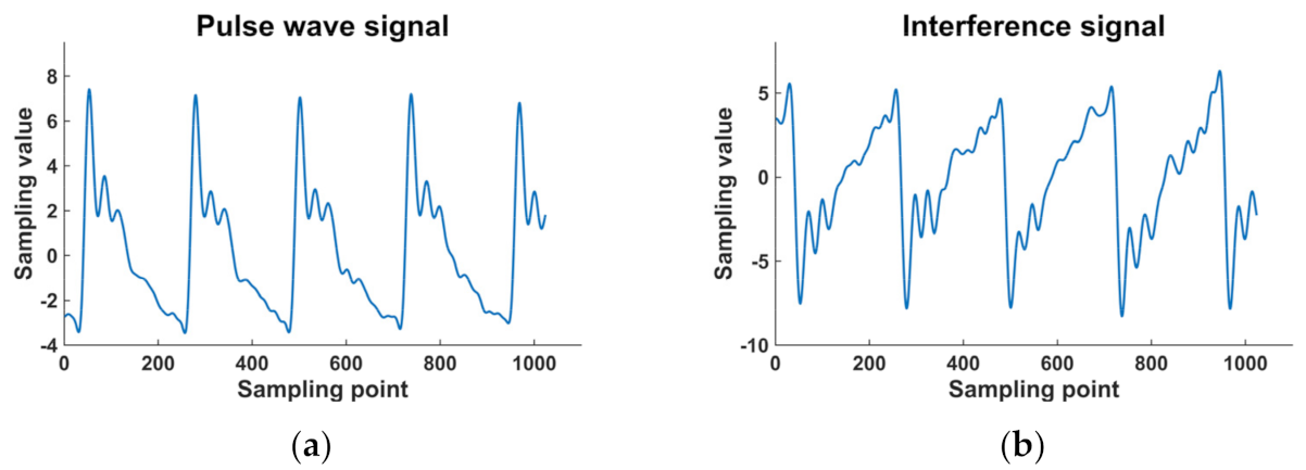
2.2.2. Mechanical Analysis of Interference Signals

The output voltage value of the sensor is related to the pressure on the surface of the sensor. When the pressure on the sensor increases, the output voltage value increases. When the pressure decreases, the output voltage value decreases. Vascular pulsation drives the skin to move up and down and squeezes the sensor to generate a pulse wave signal, as shown in Figure 3a. Due to the physical connection, the adjacent sensors are forced to move up and down, which will make the contact pressure between the sensor and the skin surface change, resulting in interference signals. The interference signal is shown in Figure 3b.
In this paper, a mechanical structure model is established by using a sensor array acquisition system and one single-point signal generator to verify the above hypothesis. As shown in Figure 4, the sensor array is attached to the curved surface of the signal generator. The sensor array is attached to the curved surface of the signal generator, in which sensors B and C are in contact with the vibration point. When the vibration point moves upward, the pressure on sensors B and C increases, and the output voltage values of sensors B and C increase. Due to the upward movement of the vibration point, sensors B and C are displaced upward. Since the sensors are connected together by a bending structure, the forced movement of sensors B and C reduces the contact pressure between sensor A, sensor D and the bending surface, resulting in the reduction in the output voltage of B and C.
When the output voltage values of sensors B and C increase to the maximum value, the output voltage values of sensors A and D decrease to the minimum value. When the vibration point moves downward, the situation is reversed.
In order to verify the correctness of the above hypothesis, this study used a single vibration point signal generator to replace vascular pulsation and analyzed the impact of a single vibration point on the neighboring sensor from a mechanical point of view. As shown in Figure 5, for the convenience of description, the sensors of the sensor array are named: Sensor 1, Sensor 2, Sensor 3, through to Sensor 8. We put the vibration point at Sensor 1 and Sensor 2 and ensured that all sensors were in contact with the bending structure for signal collection.
Figure 6 shows the output signals of Sensors 1–8, respectively. Since Sensors 3, 4, 5, 6, and 7 were not in contact with the vibration point, they should not have vibration signals. However, because all the sensors were fixed on the bending structure, the phenomenon described above occurred. This signal is referred to as an interference wave in this article. Compared with vibration signal, the interference wave has the same period, the shape is similar, and the phase difference is 180°. Due to the attenuation characteristics of signal transmission, the signal strength of the interference wave is lower than the vibration signal. As the distance increases, the attenuation of the interference signal increases.

2.3. Interference Signal Recognition Based on CNN

2.3.1. Signal Preprocessing
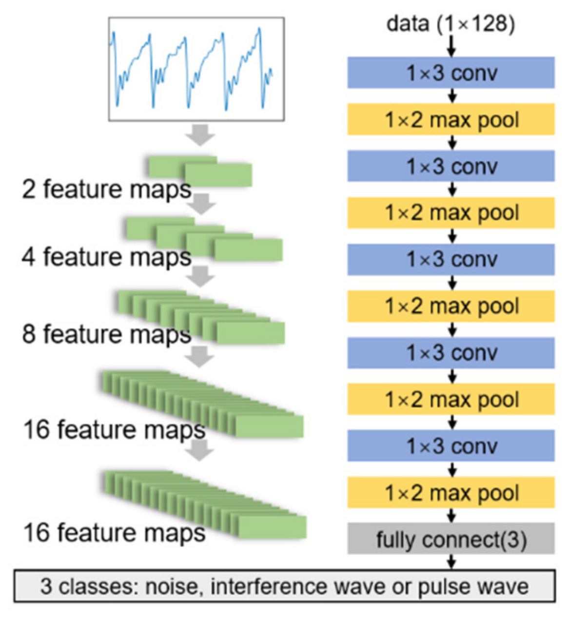
This study used a MEMS sensor array acquisition system to collect signals from the radial artery of one subject’s wrist. During the collection process, the data of 11 pressure sections from 10 to 120 mmHg were collected at a step value of 10 mmHg, and the pressure was maintained for 15 s in each step. In order to make the classification and labeling of the data more accurate, preprocessing was necessary. To carry this out, firstly, one data point from each pressure segment of the original data was selected. Next, a 0.5 Hz–25 Hz bandpass filter was used to filter the selected data [21]. Then, a data value of a specific length was intercepted from the filtered data. In order to enhance the model’s anti-interference ability, the data were normalized. Lastly, the data were labeled and inputted into the data set.

2.3.2. CNN Model

CNNs are models of deep learning that are good at extracting global features. CNNs also show strong adaptability in the recognition of one-dimensional pulse wave signals.
Figure 7 is a one-dimensional CNN model. The input of the one-dimensional CNN model is a one-dimensional form of data, so the convolution kernel adopts a one-dimensional structure accordingly. The output of each convolution and pooling is also a one-dimensional feature vector. The model is mainly composed of a CONV (convolutional) layer and an FC (fully connected) layer. The CONV layer mainly implements feature extraction, which includes three operations: convolution operation, activation operation, and pooling operation. After the CONV layer, the FC layer fuses the feature and finds the relationship between the “learned” output vector and the feature vector.

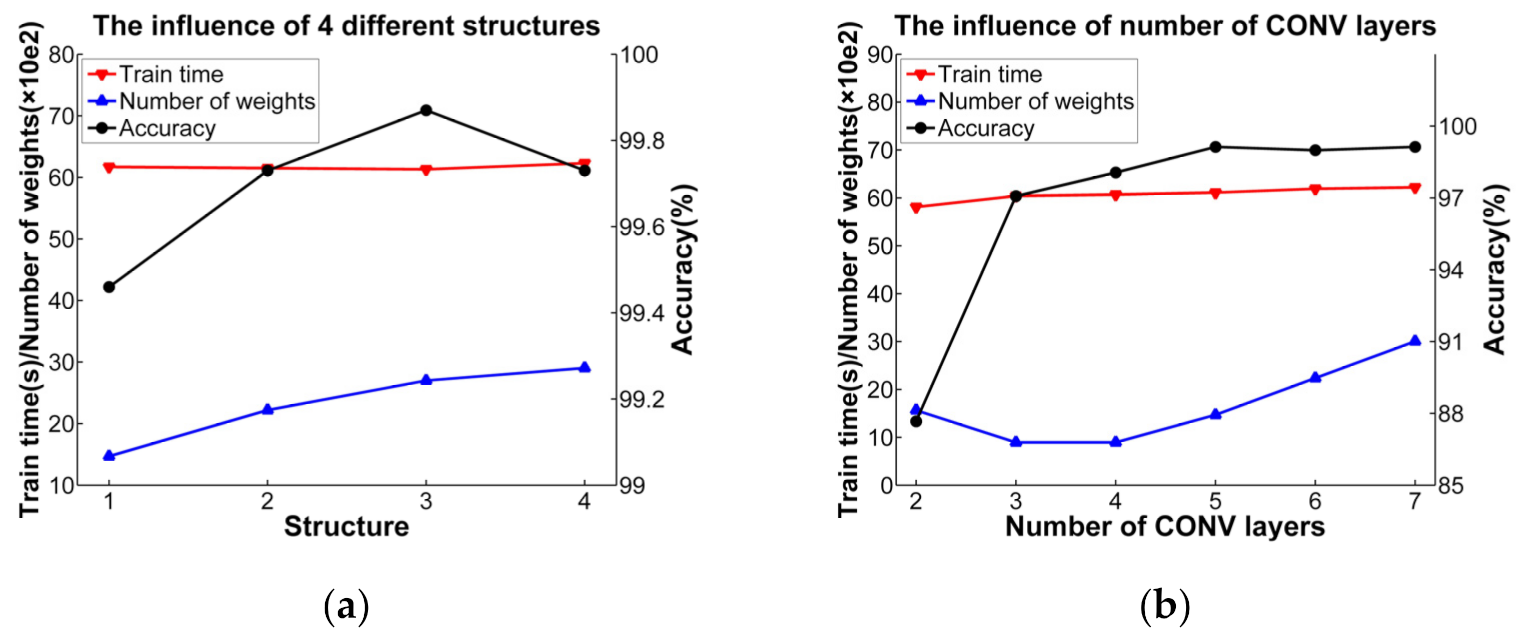
2.3.3. CNN Model Design

In order to design a CNN with high accuracy and fewer parameters, and find the relevant model parameters, we conducted a set of experiments. The experimental software and hardware development environment is: PyTorch 1.4.0 (CUDA version), Python 3.8.5, and an NVIDIA GeForce GTX 1660Ti GPU.
In order to reduce the number of calculations, this article down-sampled the original input signal of 1024 sampling points, and used signals with lengths of 512, 256, 128, 64, and 32, respectively. The corresponding sampling frequencies of 109 Hz, 54.5 Hz, 27.25 Hz, 13.625 Hz and 6.8125 Hz satisfied the Nyquist sampling theorem. As shown in Figure 8, the results show that when the input signal length was less than 128, the accuracy of the model was reduced.
In CNN, a large part of the weight parameters and calculations come from the first fully connected layer. In order to reduce the weight parameters, this paper proposes reducing the number of FC layers and neurons. This paper proposes two structures of the FC layer; the experiment results are shown in Table 1.
In order to reduce the weight parameters and computational complexity, this paper proposes four structures by modifying the ratio of input and output channels, as shown in Table 2. In this case, m and n represent the number of input channels and the number of output channels, respectively. As shown in Figure 9a, under the premise of high accuracy and low training time, structure 1 had fewer weight parameters.
When the number of CNOV layers is 2, 3, 4, 5, 6, and 7, the influence of the number of convolutional layers on the model is shown in Figure 9b. It can be seen that when the number of layers is 3, the number of weight parameters is the least and the number of layers has little effect on the accuracy of the model.
According to the above experiment, the final CNN selected is shown in Figure 10, which contains five CONV layers, one FC layer, and 1470 parameters.

2.4. Design of CNN Accelerator Based on FPGA

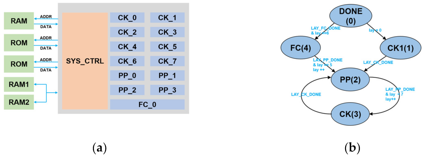
2.4.1. Overall Architecture

As shown in Figure 11a, the CNN hardware acceleration structure includes three parts: the arithmetic module, the storage module and the control module. The arithmetic module includes the convolution kernel (CK) module, the post-processing (PP) module and the FC module. The CK module is used to perform convolution sliding window operations. The PP module is used to implement the accumulation of multiple input feature maps, the ReLU activation function and the calculation of maximum pooling. The FC module implements the fully connected layer. These computing modules all use pipelined calculations.
The trained weight parameters and bias parameters are stored in two ROMs, and the input data are stored in a RAM. In this study, the output of each computing module was placed in the on-chip buffer area, which helped to reduce the data access. We used two BRAM blocks to form a ping-pong structure. There are two sets of read and write ports. The first layer can read RAM1 and write RAM2, and the next layer can write RAM1 and read RAM2. Therefore, the ping-pong buffer can avoid overlap and improve performance.
The input data of the CONV layer of the first layer are read from the RAM, and the input data of other layers are from the on-chip BRAM. In order to distinguish the first CONV layer, a state machine is used in the control module. As shown in Figure 11b, the system first executes the CK and PP of the first CONV layer, and then executes the CK and PP of the other layers in the sequence. When the final FC finished, one result is output.

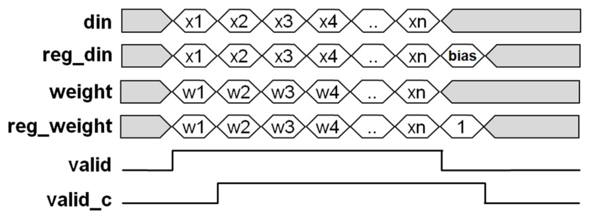
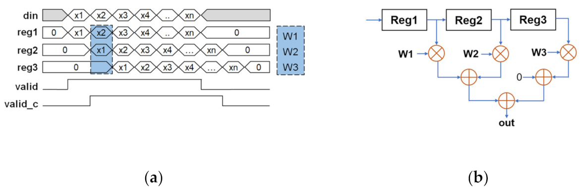
2.4.2. Computing Module Design

The CK module is a computationally intensive component in the system. In order to increase the performance, a pipelined design was adopted. In the convolution window, each cycle completes the multiplication and accumulation of a unit. After the calculation of a convolution window is completed, the convolution window moves forward to the next operation. The structure of the processing element (PE) in the CK module is shown in Figure 12. In the CNN algorithm, we fill 0 before and after the input signal.
After the convolution operation, a PP (post-processing) module was used to implement accumulation, ReLU and max-pooling. The accumulation after the convolution operation and the accumulation of the offset are all realized by the accumulator. The ReLU activation function is realized by judging the sign bit of the data. The maximum pooling is completed by using a comparator.
As shown in Figure 13, in the FC module, the calculations between the output neuron nodes are parallel, and the calculation of a single output neuron node adopts a pipeline method. An input node read in each cycle is multiplied by the weight and then accumulated. When the product of all inputs and weights is added, it is output after offset. After the accumulation finished, the offset was added. The whole module is implemented with multipliers and accumulators. At the falling edge of valid, the input data were filled with 0, and the weight with 1.

3. Results

3.1. Interference Signal Recognition Based on CNN

3.1.1. Data Sources

In this experiment, 50 cases of data were collected with the MEMS sensor array collection system, including 38 male subjects and 12 female subjects. All subjects were in the age range of 20–40 years old. There were three types of raw data: pulse wave, interference wave, and irregular noise. The final data set was composed of 1650 samples, including 550 pulse waves, 550 interference waves, and 550 irregular noise waves. We randomly sampled 500 pulse waves, 500 interference waves, and 500 noise waves as the training set, and the remaining samples were composed of the test set. The platform for generating the data set was MATLAB 2019a.

3.1.2. Model Training

Other parameter settings of this model are shown in Table 3. The loss curve and accuracy curve obtained during one training session are shown in Figure 14.

3.1.3. Test Results

Confusion matrixes are usually used to evaluate the performance of the model. For each category i in the multi-class problem, all samples except the ith category can be regarded as negative samples. The accuracy, precision, recall,   F 1 , and m a c r o F 1 can be calculated by the following equation:
A c c u r a c y i = T P + T N T P + T N + F P + F N .
P r e c i s i o n i = T P T P + F P ,
R e c a l l i = T P T P + F N ,
F 1 i = 2 × P r e c i s i o n i × R e c a l l i P r e c i s i o n i + R e c a l l i ,
m a c r o F 1 = 1 n i = 1 n F 1 i ,
T P   is true positive: the number of positive segments classified correctly. T N is true negative: the number of negative segments classified correctly. F P is false positive: the number of negative segments classified incorrectly. F N is false negative: the number of positive segments classified incorrectly.
As shown in Table 4, we obtained a confusion matrix after testing 150 samples.
The classification accuracy of this model was 99.3%. The   m a c r o F 1 calculated by the formula was 0.99, which shows that the model has a highly stable classification ability for the interference wave.

3.2. FPGA Simulation and Testing

We implemented the CNN accelerator on the Xilinx FPGA platform. This design was implemented on the Xilinx xc7a100tfgg484-2 platform, using a pipeline structure. The synthesis tool was Vivado2018.03.
The resource utilization rate of the CNN accelerator in this paper at 100 MHz operating frequency is shown in Table 5.
Although our CNN model was relatively simple, the power consumption of the CNN accelerator was also very low, consuming only 0.673 W at a working frequency of 100 MHz.

4. Conclusions

In this paper, we propose an FPGA-based CNN accelerator to identify interference signals. Firstly, we performed a mechanical analysis of the interference phenomenon between channels and discussed the reason for the interference signal. Then, we used CNN to identify the interference signal. In order to reduce the weight parameters, we specially designed a CNN model based on experiments. The classification accuracy of the model is 99.3%. Finally, we implemented a CNN accelerator on Artix XC7A100T, which cost only 0.673 W under a working frequency of 100 MHz.
Signal interference in multi-channel systems is an unavoidable natural phenomenon, especially in communication systems. Due to some factors on the signal transmission path, the signal interference appears on adjacent channels and sub-adjacent channels, which affects the entire communication system. In Chinese medicine, the human wrist is divided into three positions, called Cun, Guan, and Chi. The three positions carry different physiological and pathological information. The sensor array group covering the three positions has one physical connection. The vibration of one sensor array forces the other sensor array to move, which creates channel interference. In future research, our team will explore the formation mechanism of the adjacent channel interference and suppress this phenomenon algorithmically.

Author Contributions

Conceptualization, L.H., X.G., Y.Z., Z.L. and H.Z.; methodology, L.H. and X.G.; software, L.H. and H.X.; validation, L.H. and H.X.; formal analysis, L.H. and X.G.; investigation, L.H.; resources, Y.Z., Z.L., J.Z. and H.Z.; data curation, L.H., X.G. and Y.Z.; writing—original draft preparation, L.H.; writing—review and editing, L.H., X.G., H.X., Y.Z. and H.Z.; project administration, Y.Z., Z.L., J.Z. and H.Z. All authors have read and agreed to the published version of the manuscript.

Funding

This research was funded by the Key Deployment Project of the Chinese Academy of Sciences, grant number ZDRW-ZS-2021-1.

Data Availability Statement

The raw/processed data required to reproduce these findings cannot be shared at this time as the data also form part of an ongoing study.

Acknowledgments

All authors of this manuscript have directly participated in the planning, execution, and/or analysis of this study. The contents of this manuscript have not been copyrighted or published previously. All authors have no objection to the ranking order.

Conflicts of Interest

The authors declare no conflict of interest.

References

  1. Che, X.S.; Xu, X.Q.; Sun, J.; Xu, H. Research on Pulse Power Spectrum Calculation Method Based on TCM. In Proceedings of the IEEE International Conference on Communication Software and Networks (ICCSN), Chengdu, China, 6–7 June 2015; pp. 333–337. [Google Scholar]
  2. Khandai, S.K.; Jain, S.K. Comparison of Sensors Performance for the Development of Wrist Pulse Acquisition System. In Proceedings of the IEEE Region 10 Conference (TENCON), Penang, Malaysia, 5–8 November 2017; pp. 2870–2875. [Google Scholar]
  3. Thakker, B.; Vyas, A.L. Frequency domain analysis of radial pulse in abnormal health conditions. In Proceedings of the IEEE EMBS Conference on Biomedical Engineering and Sciences (IECBES), Kuala Lumpur, Malaysia, 30 November–2 December 2010; pp. 227–231. [Google Scholar] [CrossRef]
  4. Hu, C.-S.; Chung, Y.-F.; Yeh, C.-C.; Luo, C.-H. Temporal and Spatial Properties of Arterial Pulsation Measurement Using Pressure Sensor Array. Evid. Based Complement. Altern. Med. 2012, 2012, 1–9. [Google Scholar] [CrossRef] [PubMed] [Green Version]
  5. Peng, J.-Y.; Lu, M.S.C. A Flexible Capacitive Tactile Sensor Array with CMOS Readout Circuits for Pulse Diagnosis. IEEE Sens. J. 2015, 15, 1170–1177. [Google Scholar] [CrossRef]
  6. Ji, M.N.; Meng, X.F.; Nie, J.; Wang, Y.Q.; Lin, L.W. A new type of bionics based piezoelectric heartbeat sensor used in pulse-taking for health warning. In Proceedings of the 17th IEEE SENSORS Conference, New Delhi, India, 28–31 October 2018; pp. 752–755. [Google Scholar]
  7. Nguyen, T.V.; Mizuki, Y.; Tsukagoshi, T.; Takahata, T.; Ichiki, M.; Shimoyama, I. MEMS-Based Pulse Wave Sensor Utilizing a Piezoresistive Cantilever. Sensors 2020, 20, 1052. [Google Scholar] [CrossRef] [PubMed] [Green Version]
  8. Loukogeorgakis, S.; Dawson, R.; Phillips, N.; Martyn, C.N.; Greenwald, S.E. Validation of a device to measure arterial pulse wave velocity by a photoplethysmographic method. Physiol. Meas. 2002, 23, 581–596. [Google Scholar] [CrossRef] [PubMed]
  9. Zhang, D.Y.; Zhang, L.; Zhang, D.; Zheng, Y.P. Wavelet based analysis of Doppler ultrasonic wrist-pulse signals. In Proceedings of the 1st International Conference on Biomedical Engineering and Informatics, Sanya, China, 27–30 May 2008; p. 539. [Google Scholar]
  10. Zhang, H.; An, M.; Bu, Z.; Zheng, Z. Fingertip pulse wave extraction based on ultrasonic echo signal. Chin. J. Med. Phys. 2020, 37, 1306–1311. [Google Scholar]
  11. Liu, S.; Zhang, S.; Zhang, Y.; Geng, X.; Zhang, J.; Zhang, H. A novel flexible pressure sensor array for depth information of radial artery. Sens. Actuators Phys. 2018, 272, 92–101. [Google Scholar] [CrossRef]
  12. Wang, P.; Zuo, W.M.; Zhang, D. A Compound Pressure Signal Acquisition System for Multichannel Wrist Pulse Signal Analysis. IEEE Trans. Instrum. Meas. 2014, 63, 1556–1565. [Google Scholar] [CrossRef]
  13. Shin, K.Y.; Jeon, S.C.; Nam, K.C.; Huh, Y. Implementation of Array Sensor Module for a Radial Artery Tonometry. In Proceedings of the 32nd Annual International Conference of the IEEE Engineering-in-Medicine-and-Biology-Society (EMBC 10), Buenos Aires, Argentina, 30 August–4 September 2010; pp. 6397–6400. [Google Scholar]
  14. Wang, D.M.; Zhang, D. Analysis of pulse waveforms preprocessing. In Proceedings of the International Conference on Computerized Healthcare (ICCH), Hong Kong, China, 17–18 December 2012; pp. 174–179. [Google Scholar]
  15. Katsuura, T.; Izumi, S.; Yoshimoto, M.; Kawaguchi, H.; Yoshimoto, S.; Sekitani, T. Wearable pulse wave velocity sensor using flexible piezoelectric film array. In Proceedings of the IEEE Biomedical Circuits and Systems Conference (BioCAS), Turin, Italy, 19–21 October 2017; pp. 1–4. [Google Scholar] [CrossRef]
  16. Wang, D.M.; Zhang, D.; Lu, G.M. An Optimal Pulse System Design by Multichannel Sensors Fusion. IEEE J. Biomed. Health Inform. 2016, 20, 450–459. [Google Scholar] [CrossRef] [PubMed]
  17. Kaisti, M.; Leppanen, J.; Lahdenoja, O.; Kostiainen, P.; Pankaala, M.; Meriheina, U.; Koivisto, T.; IEEE. Wearable Pressure Sensor Array for Health Monitoring. In Proceedings of the 44th Computing in Cardiology Conference (CinC), Rennes, France, 24–27 September 2017. [Google Scholar]
  18. Chen, J.Z.; Sun, K.; Zheng, R.; Sun, Y.; Yang, H.; Zhong, Y.F.; Li, X.X. Three-Dimensional Arterial Pulse Signal Acquisition in Time Domain Using Flexible Pressure-Sensor Dense Arrays. Micromachines 2021, 12, 569. [Google Scholar] [CrossRef] [PubMed]
  19. Hu, X.; Zhu, H.; Xu, J.; Xu, D.; Dong, J.; IEEE. Wrist Pulse Signals Analysis based on Deep Convolutional Neural Networks. In Proceedings of the IEEE Conference on Computational Intelligence in Bioinformatics and Computational Biology, Honolulu, HI, USA, 21–24 May 2014. [Google Scholar]
  20. Chen, C.L.; Li, Z.Q.; Zhang, Y.T.; Zhang, S.L.; Hou, J.N.; Zhang, H.Y. A 3D Wrist Pulse Signal Acquisition System for Width Information of Pulse Wave. Sensors 2020, 20, 11. [Google Scholar] [CrossRef] [PubMed] [Green Version]
  21. Zou, H.; Zhang, Y.; Zhang, J.; Chen, C.; Geng, X.; Zhang, S.; Zhang, H. A Novel Multi-Dimensional Composition Method Based on Time Series Similarity for Array Pulse Wave Signals Detecting. Algorithms 2020, 13, 297. [Google Scholar] [CrossRef]
Figure 1. Acquisition device for sensor array signals. (a) Photograph of the pulse wave acquisition system. (b) Schematic diagram of the circuit structure of the sensor. (c) Schematic diagram of the MEMS sensor array. (d) Photograph of the MEMS sensor array.
Electronics 10 02867 g001
Figure 2. Single-point vibration signal generator. (a) Structure of the single-point vibration signal generator. (b) Photo of the single-point vibration signal generator.
Electronics 10 02867 g002
Figure 3. (a) Pulse wave signal. (b) Interference signal.
Electronics 10 02867 g003
Figure 4. The mechanical structure model of the acquisition system.
Electronics 10 02867 g004
Figure 5. Schematic diagram of the MEMS sensor array.
Electronics 10 02867 g005
Figure 6. The signals of Sensor 1–8.
Electronics 10 02867 g006
Figure 7. A one-dimensional CNN model.
Electronics 10 02867 g007
Figure 8. The influence of the length of data.
Electronics 10 02867 g008
Figure 9. The influence of 4 different structures and the number of CONV layers. (a) The influence of 4 different structures. (b) The influence of the number of CONV layers.
Electronics 10 02867 g009
Figure 10. The CNN model has relatively high accuracy, shorter training time, and less weight.
Electronics 10 02867 g010
Figure 11. (a) CNN accelerator structure. (b) State transition diagram of controller.
Electronics 10 02867 g011
Figure 12. The structure of PE in the CK module. (a) PE’s timing diagram. (b) PE’s RTL circuit design.
Electronics 10 02867 g012
Figure 13. FC’s timing diagram.
Electronics 10 02867 g013
Figure 14. The trend curves of loss and accuracy during training. (a) The trend curves of loss. (b) The trend curves of accuracy.
Electronics 10 02867 g014
Table 1. Different structures of FC layers.
Structure of FC LayersAccuracy (%)Train Time(s)Number of Weights
FC1 (20) + FC2 (3)99.861.53848
FC1 (3)99.8761.32700
Table 2. Different structures of CNN models.
StructureCONV1CONV2CONV3CONV4CONV5
1(1-2)(2-4)(4-8)(8-16)(16-16)
2(1-4)(4-8)(8-16)(16-16)(16-16)
3(1-4)(4-16)(16-16)(16-16)(16-16)
4(1-8)(1-16)(16-16)(16-16)(16-16)
Table 3. Parameter settings of the CNN model.
Parameter NameValue
Kernel size1 × 3
Pooling size1 × 2
Loss functionCrossEntropyLoss
OptimizerAdam
Learning rate0.001
Batch size100
epochs50
Table 4. Confusion matrix for the test.
Predicted Class
InterferencePulseNoise
Actual classInterference5000
Pulse0500
Noise1049
Table 5. Resource utilization in vivado synthesis report.
ResourceUtilizationAvailableUtilization%
LUT18,76163,40029.59
FF30,063126,80023.71
BRAM53.5013539.63
DSP14724061.25
BUFG2326.25
Publisher’s Note: MDPI stays neutral with regard to jurisdictional claims in published maps and institutional affiliations.

