Article

Joint Vital Signs and Position Estimation of Multiple Persons Using SIMO Radar

by
Ibrahim Kakouche
1,*,
Hamza Abadlia
1,
Mohammed Nabil El Korso
2,
Ammar Mesloub
3,
Abdelmadjid Maali
1 and
Mohamed Salah Azzaz
1
1
Laboratoire Systèmes Électroniques et Numériques, École Militaire Polytechnique, Bordj El-Bahri 16111, Algeria
2
Laboratory for Energetic, Mechanics and Electromagnetism, Paris-Nanterre University, 92000 Ville-d’Avray, France
3
Laboratoire Traitement du Signal, École Militaire Polytechnique, Bordj El-Bahri 16111, Algeria
*
Author to whom correspondence should be addressed.
Electronics 2021, 10(22), 2805; https://doi.org/10.3390/electronics10222805
Submission received: 14 September 2021 / Revised: 10 November 2021 / Accepted: 15 November 2021 / Published: 16 November 2021
(This article belongs to the Special Issue Modern Techniques in Radar Systems)

Abstract

:
Respiration rate monitoring using ultra-wideband (UWB) radar is preferred because it provides contactless measurement without restricting the person’s privacy. This study considers a novel non-contact-based solution using a single-input multiple-output (SIMO) UWB impulse radar. In the proposed system, the collected radar data are converted to several narrow-band signals using the generalized Goertzel algorithm (GGA), which are used as the input of the designed phased arrays for position estimation. In this context, we introduce the incoherent signal subspace methods (ISSM) for the direction of arrivals (DOAs) and distance evaluation. Meanwhile, a beam focusing approach is used to determine each individual and estimate their breathing rate automatically based on a linearly constrained minimum variance (LCMV) beamformer. The experimental results prove that the proposed algorithm can achieve high estimation accuracy in a variety of test environments, with an error of 2%, 5%, and 2% for DOA, distance, and respiration rate, respectively.

1. Introduction

Non-contact vital sign (VS) detection, such as respiration rate, built upon a radio frequency (RF)-based system has attracted a great deal of interest in recent years. It is used in a growing field of applications, such as healthcare and clinical assistance, sleep and baby monitoring, survivor rescue and research operations, through the wall human detection, and human activity classification [1,2,3,4,5,6,7,8,9]. Recently, the impulse response ultra wide-band (IR-UWB) radar has gained more attention thanks to its high-range resolution, good penetration capability, and low power consumption [10,11].
The use of RF signals for VS waveform extraction lies in the detection of the chest motion associated with the VS activities of a human subject. Specifically, it is based on the emission and reception of electromagnetic (EM) waves. Notably, the phase variation on the received signal is exploited for this purpose [12]. To do so, several radar types have been investigated, including unmodulated continuous wave (CW) [13], frequency-modulated continuous-wave (FMCW) [14], step frequency continuous-wave (SFCW) [15], and IR-UWB [4]. Meanwhile, many signal processing techniques have been proposed, covering clutter rejection, human localization, and VS estimation [16,17,18,19,20,21]. Despite the great advances in the field, most research has focused on a single target for VS measurement. To better deal with complex and critical scenarios, such as people buried under debris, multiple-person VS motioning plays an important role in addressing these scenarios [5,8].
To date, two approaches have been mainly used to achieve the VS measurement of multiple persons. The first solution requires the range information associated with the human targets to separate their VS signals. In this context, a single-input single-output (SISO) radar is used for this purpose, namely FMCW, SFCW, or IR-UWB platforms [22]. Nevertheless, it is still difficult to obtain reliable separation when the persons are located at the same distance from the radar. The second one separates the VS signals based on the incident angle information. To this end, spatially distributed antennas have been exploited in designing the radar system, such as single-input multiple-output (SIMO) [8] and multiple-input multiple-output (MIMO) radars [6]. In particular, digital beamforming (DBF) plays an important role in beam scanning and beam focusing tasks thanks to its low-complexity structure, good control flexibility, and high accuracy [8].
In this work, a SIMO IR-UWB radar prototype is presented. The proposed system is based on a single IR-UWB radar in which eight spatially distributed antennas are connected to its receiving channel through a UWB RF switch. To deal with the array signal processing-based model, we propose a proper pre-processing step to obtain a multi-variant narrow-band signal via the generalized Goertzel algorithm (GGA) [23]. Further, we consider an incoherent signal subspace method (ISSM) for direction of arrival (DOA) estimation [24]. In particular, we use the incoherent multiple signal classification (IMUSIC) to estimate the incident angle of each person [25,26]. Then, we perform beam focusing at each estimated angle for VS separation using a linearly constrained minimum variance (LCMV) beamformer [27]. Finally, the respiration rate is estimated for each person by analyzing the spectrum of the separated signals.
In summary, the main contributions of this work are as follows:
  • The proposed SIMO IR-UWB radar system allows us to simultaneously measure the VSs of spaced persons at the same distance from the radar. It offers a low-cost and good solution for the non-contact Vs measurement of multiple persons in sleep and baby monitoring scenarios;
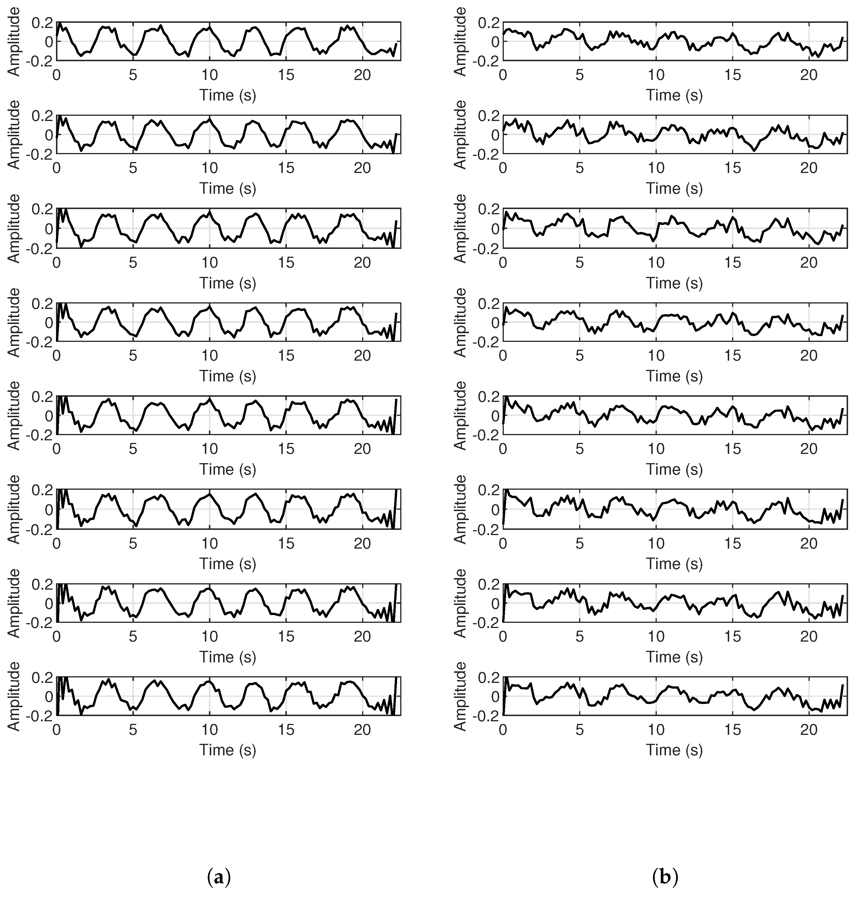
  • The chest motions of multiple targets are accurately separated with the combination of the IMUSIC and LMCV algorithms. The respiration rate estimation is significantly enhanced by forming individual narrow beam focusing on the chest regions associated with each person;
  • The experimental results are presented to investigate the performance of the proposed system, showing that our proposed method outperforms the state of the art.
The remainder of this paper is organized as follows. Section 1 presents the mathematical model of the IR-UWB SIMO radar and the problem setup. In Section 2, we tackle the estimation procedure of position and respiration rate for each person. Experimental results and numerical analyses are described in Section 3. Section 4 concludes this work.

2. Mathematical Model

UWB impulse radar has been widely used for VS detection thanks to its high-range resolution. In this context, it transmits very short pulses, usually in the order of picoseconds, to the human subject. As the electromagnetic wave returns from the chest’s body, the VS motions, which introduce a small displacement (typically in the order of millimeters) on the chest, will produce a phase variation in the received signal [12].

2.1. Received Signal for SISO Radar

Consider a finite number of persons L with incident angles θ = [ θ 0 1 , θ 0 2 , . . . , θ 0 L ] over a limited region, where the received signal, from L persons, can be simplified as:
r ( t , τ ) = l = 1 L α l p ( τ τ l ( t ) ) , l = 1 , 2 , . . . , L .
where t and τ denote the slow and fast time indexes, respectively. p ( τ ) represents the transmitted pulse. α l and τ l ( t ) are the attenuations and the time of arrival (TOA) associated with the l t h person, respectively. These letters depend on the radar cross-section (RCS) of the human subject and its distance from the radar d 0 l . Assuming that the human chest remains stationary during the coherent processing interval (CPI), usually in the order of milliseconds, the TOA in Equation (1) is expressed as:
τ l ( t ) = 2 d 0 l + d l ( t ) c
where d l ( t ) depicts the chest displacement of the l t h person, which can be expressed as [4]:
d l ( t ) = d r l cos ( 2 π f r l t )
where d r l and f r l represent the maximum displacement of the chest and the respiration frequency associated with the l t h person, respectively.

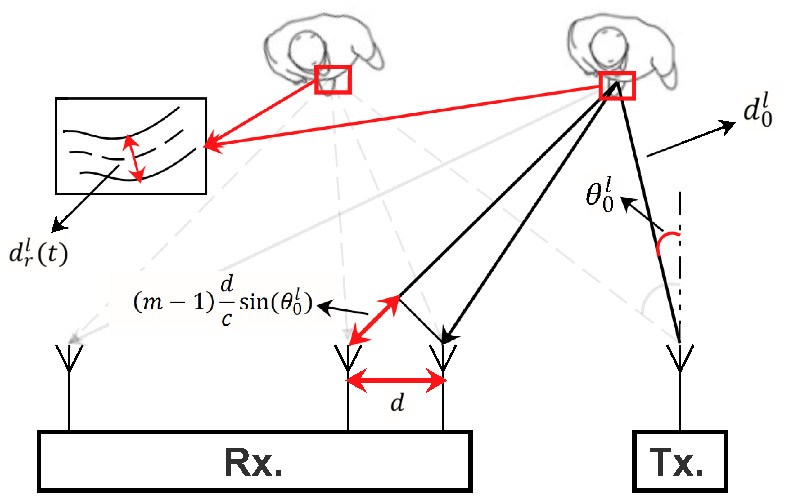
2.2. Received Signal for SIMO Radar

In our scheme, we consider a uniform linear array (ULA) composed of M antenna receivers. Depending on the incident angle of each person, the received signal at the m t h antenna can be expressed as:
r m ( t , τ ) = l = 1 L α l p ( τ τ m l ( t ) ) + w m ( t , τ ) , m = 1 , 2 , . . . , M .
where w m ( t , τ ) represents the measurement noise. Using the first antenna as a reference, τ m l ( t ) in Equation (4) can be derived as:
τ m l ( t ) = 2 d 0 l + d r l ( t ) c + ( m 1 ) d c sin ( θ 0 l )
where d depicts the inter-distance of the antenna array. Figure 1 illustrates the receiving signal model of the SIMO radar.

3. Position and VS Estimation

In this section, we first establish an appropriate SIMO radar based on a single UWB impulse transceiver P440 for VS and position estimation. Then, we develop a method to transom the collected UWB data into multiple narrow-band signals. Next, we explain how to estimate the respiration rate of each person based on their estimated incident angles.

3.1. SIMO Radar System Structure

Figure 2 illustrates the basic modules of the SIMO radar system adopted in this work. Specifically, the impulse UWB transceiver P440 is used to transmit and receive data. In particular, it transmits a Gaussian impulse RF signal with a carrier frequency of 4.3 GHz and a bandwidth of 2.2 GHz. It acts as a short-range coherent radar using the monostatic radar module (MRM). On the other hand, a broadband RF switch HMC321A (covering a band from DC to 8 GHz) is used to select one specific antenna receiver at each scan to build an array receiver. Specially, we use a Raspberry Pi 4 to control and automate this process. Finally, the collated data are transferred to the PC via a WiFi connection for signal processing.

3.2. Algorithm Scheme

The joint estimation approach exploits the spatial and spectrum, in the fast time domain, information of the received signals for estimating the human positions and separating their VS waveforms. Moreover, the temporal information, in the slow time domain, is used for respiration rate estimation. Figure 3 illustrates the process of the proposed method.

3.2.1. Pre-Processing

In this section, we introduce a pre-processing step to transform the IR-UWB signals to multiple narrow-band signals. Specifically, we use the GGA to evaluate the Fourier transform (FT) at specific frequency indexes. Then, a complex band pass filter is applied to remove the clutter response and negative frequencies and enhance the VS waveform [4].
Applying the FT to Equation (4), in the fast time domain, reads:
R m ( t , ω ) = l = 1 L α l P ( ω ) e j ω τ m l ( t ) + C m ( ω ) + W m ( t , ω )
where P ( ω ) , C m ( ω ) , and W m ( t , ω ) represent the FT of the transmitted pulse, the clutter response, and the measurement noise, receptively. Inserting Equation (5) into Equation (6) results in:
R m ( t , ω ) = l = 1 L α l P ( ω ) e j β 0 l ( ω ) e j β ( ω ) ( m 1 ) sin ( θ 0 l ) e j β r l ( ω ) sin ( 2 π f r l t ) + C m ( ω ) + W m ( t , ω )
where β ( ω ) = ω d c , β 0 l ( ω ) = 2 ω d 0 l c , and β r l ( ω ) = 2 ω d r l c . Furthermore, e j β r l ( ω ) sin ( 2 π f r l t ) in Equation (7) can be expressed, using the Bessel functions, as:
e j β r l ( ω ) sin ( 2 π f r l t ) = n = J n ( β r l ( ω ) ) e j 2 π n f r l t
where J n depicts the first kind of Bessel function of order n. By further taking into consideration that d r l is small, in the order of millimeters, and regarding the range of ω , in the order of GHz, the quantity β r l ( ω ) is close to zero. Hence, Equation (8) can be simplified, retaining only the Bessel functions from up to the second order, as:
e j β r l ( ω ) sin ( 2 π f r l t ) = J 0 ( β r l ( ω ) ) + J 1 ( β r l ( ω ) ) ( e j 2 π f r l t + e j 2 π f r l t )
Inserting Equation (9) into Equation (7) reads:
R m ( t , ω ) = l = 1 L α l J 1 ( β r l ( ω ) ) P ( ω ) e j β 0 l ( ω ) e j β ( ω ) ( m 1 ) sin ( θ 0 l ) ( e j 2 π f r l t + e j 2 π f r l t ) + C m ( ω ) + W m ( t , ω )
in which:
C m ( ω ) = l = 1 L α l J 0 ( β r l ( ω ) ) P ( ω ) e j β 0 l ( ω ) e j β ( ω ) ( m 1 ) s i n ( θ 0 l )
At this point, we apply the CBPF [28], presented in our previous work [4], to remove C m ( ω ) and enhance the VS waveform. The result of such a filter can be expressed as:
X m ( t , ω ) = l = 1 L e j β ( ω ) ( m 1 ) s i n ( θ 0 l ) S l ( t , ω ) + N m ( t , ω )
where S l ( t , ω ) = α l J 1 ( β r l ( ω ) ) P ( ω ) e j β 0 l ( ω ) e j 2 π f r l t , which represents the source signal associated with the l t h person, and N m ( t , ω ) depicts the filtered noise of W m ( t , ω ) . Notice that, for each ω , we obtain an array signal processing-based model, which can be written in matrix form as:
X ( t , ω ) = A ( θ , ω ) S ( t , ω ) + N ( t , ω )
in which:
X ( t , ω ) = [ X 1 ( t , ω ) , X 2 ( t , ω ) , . . . , X m ( t , ω ) , . . . , X M ( t , ω ) ] T , N ( t , ω ) = [ N 1 ( t , ω ) , N 2 ( t , ω ) , . . . , N m ( t , ω ) , . . . , N M ( t , ω ) ] T , S ( t , ω ) = [ S 1 ( t , ω ) , S 2 ( t , ω ) , . . . , S 2 ( t , ω ) , . . . , S l ( t , ω ) ) ] T , A ( θ , ω ) = [ a ( θ 0 1 , ω ) , a ( θ 0 2 , ω ) , . . . , a ( θ 0 l , ω ) , . . . , a ( θ 0 L , ω ) ] ,
where a ( θ 0 l , ω ) = [ 1 , e j β ( ω ) s i n ( θ 0 l ) , . . . , e j β ( ω ) ( m 1 ) s i n ( θ 0 l ) , . . . , e j β ( ω ) ( M 1 ) s i n ( θ 0 l ) ] T . In view of this, the model presented in Equation (13) is established for several frequency indexes Ω = [ ω 1 , ω 2 , . . . , ω k , . . . , ω K ] , which are chosen from the IR-UWB radar frequency band. To do so, we use the GGA instead of FFT because we require a few spectral components. In such cases, the algorithm is significantly faster.

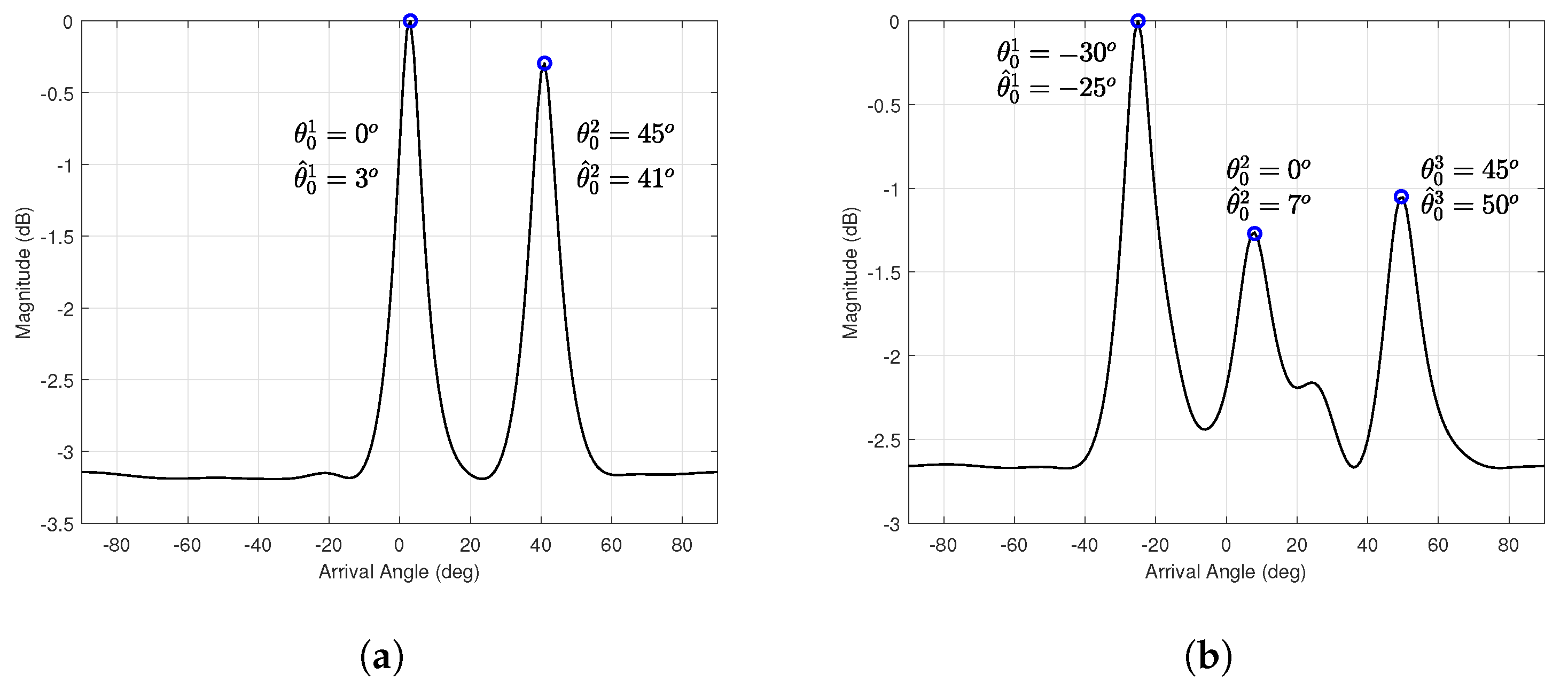
3.2.2. DOA Estimation

Initially, we perform the IMUSIC method on the received signal after the pre-processing step to estimate the DOA of each person with a high angular resolution. It is common to assume that the number of sources is known, or previously estimated by using MDL or AIC methods [29,30]. Firstly, the ideal covariance matrix is estimated using the sample covariance matrix for each frequency bin:
R ^ ( ω k ) = 1 N t = 0 N 1 X ( t , ω k ) X H ( t , ω k )
where ( . ) H represents the conjugate transpose. Then, the noise covariance matrix can be estimated, based on the eigenvalue decomposition of R ^ ( ω k ) , as:
R ^ n ( ω k ) = Q n ( ω k ) Q n H ( ω k )
where Q n ( ω ) is the estimated noise subspace obtained using the SVD on R ^ ( ω k ) for each frequency bin. Secondly, the estimated θ ^ 0 l of the l t h person can be obtained by evaluating the peaks of the following spatial spectrum function [25]:
P I M U S I C ( θ ) = k = 1 K 1 a H ( θ , ω k ) R ^ n ( ω k ) a ( θ , ω k )

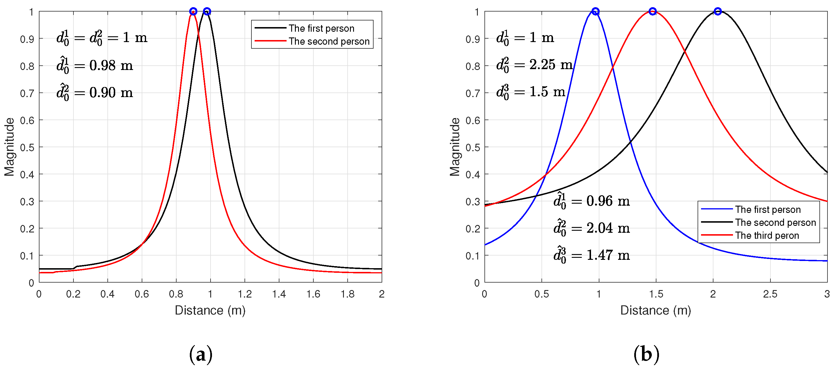
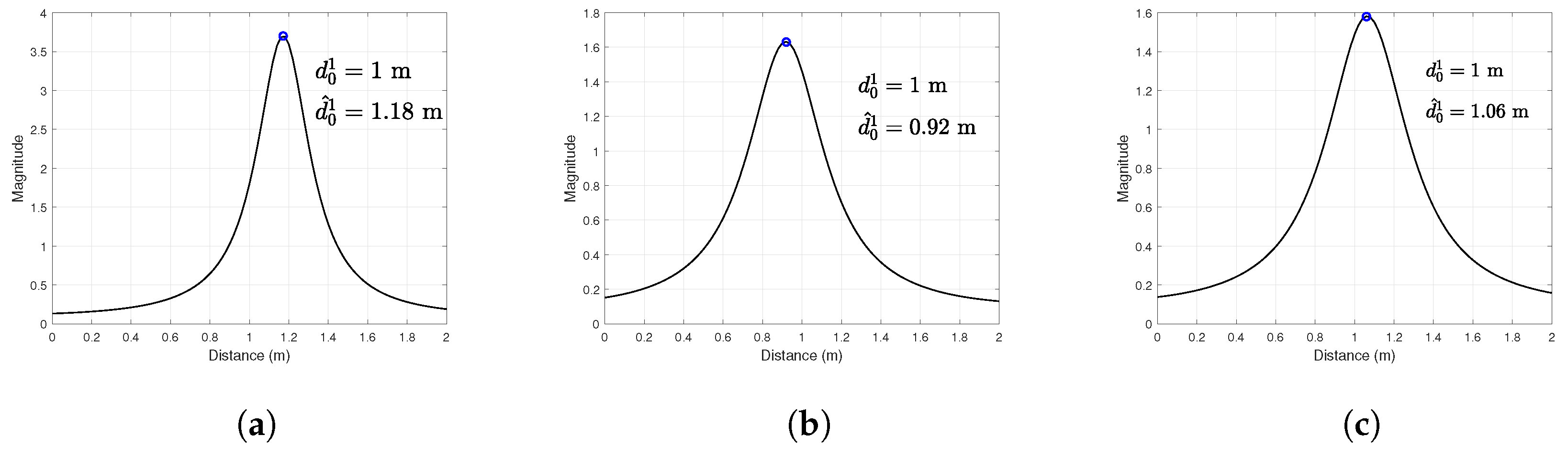
3.2.3. Distance Estimation

In order to estimate the distance of each person accurately, we use the well-known LCMV beamformer, which is widely used in acoustic array processing [31]. First, a weighted vector is designed according to certain criteria. In particular, the LCMV beamformer intends to make the desired direction θ ^ 0 l gain associated with the l t h person constant while minimizing the total output power with certain constraint conditions:
min w k w k H R ^ ( ω k ) w k s . t w k H C = f
in which:
f = [ 0 , 0 , . . . , 0 , 1 , 0 , . . . , 0 ] T C = [ a ( θ ^ 0 1 , ω ) , a ( θ ^ 0 2 , ω ) , . . . , a ( θ ^ 0 l 1 , ω ) , a ( θ ^ 0 l , ω ) , a ( θ ^ 0 l + 1 , ω ) , . . . , a ( θ ^ 0 L , ω ) ]
Based on the work in [8], the weight vector is expressed as:
w k = R ^ 1 ( ω k ) C C H R ^ 1 ( ω k ) C f
Thus, the final output signal associated with the l t h person can be expressed as:
S ^ l ( t , ω k ) = w k H X ( t , ω k )
Using Equation (12), Equation (20) can be rewritten as:
S ^ l ( t , ω k ) = S l ( t , ω k ) + e l ( t , ω k ) S ^ l ( t , ω k ) = e j 2 ω k d 0 l c s l ( t ) + e l ( t , ω k )
where s l ( t ) = A l e j 2 π f r l t , A l = α l J 1 ( β r l ( ω k ) ) P ( ω k ) , and e l ( t , ω k ) represents the estimation error. The matrix form of Equation (21) can be expressed as:
S ^ l ( t ) = a ( d 0 l ) s l ( t ) + e l ( t )
in which:
S ^ l ( t ) = [ S ^ l ( t , ω 1 ) , S ^ l ( t , ω 2 ) , . . . , S ^ l ( t , ω k ) , . . . , S ^ l ( t , ω K ) ] T , e l ( t ) = [ e l ( t , ω 1 ) , e l ( t , ω 2 ) , . . . , e l ( t , ω k ) , . . . , e l ( t , ω K ) ] T , a ( d 0 l ) = [ e j 2 ω 1 d 0 l c , e j 2 ω 2 d 0 l c , . . . , e j 2 ω k d 0 l c , . . . , e j 2 ω K d 0 l c ] T .
Notice that Equation (23) represents an array signal processing based-model. Thus, the subspace methods can be applied to estimate d 0 l . In our work, we use the MUSIC method in which the number of sources is fixed to one [32]. This procedure is repeated for each l. To this end, the VS signal of the l t h person can be extracted by applying a simple beam focusing technique as follows:
s ^ l ( t ) = a H ( d ^ 0 l ) S ^ l ( t )

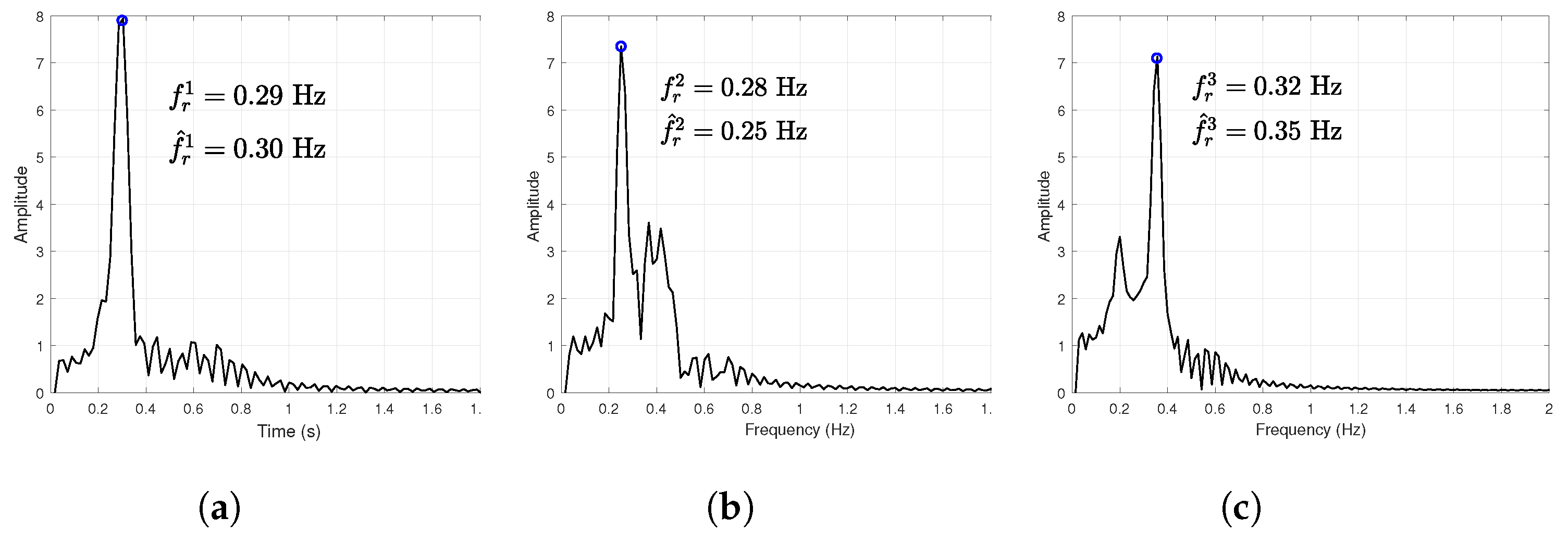
3.2.4. Respiration Rate Estimation

In this section, we focus on the estimation of respiration rate from the extracted VS waveform s ^ l ( t ) . Based on Equation (23), s ^ l ( t ) can be expressed as:
s ^ l ( t ) A l e j 2 π f r l t
Applying the FT to Equation (24) leads to:
S ^ l ( f ) A l δ ( f f r l )
where δ represents the Dirac function. Thus, f r l can be easily estimated by finding the peak of S ^ l ( f ) , which is calculated using FFT.

4. Experimental Results

In this section, we describe the experiments that were carried out to assess the performance of the proposed method. Three human subjects participated in these experiments, in which an accelerometer was attached to their chest as a ground truth device for breathing rate estimation. Several scenarios were considered to ensure the accuracy of the obtained results. A record of 30 min was achieved for different scenarios; each record was divided into several realizations of 180 s (22.5 s for each channel). The errors were calculated as follows:
Error θ = 1 N r L l = 1 L n r = 1 N r | θ 0 l θ ^ 0 l [ n r ] | | θ 0 l | × 100 % Error d = 1 N r L l = 1 L n r = 1 N r | d 0 l d ^ 0 l [ n r ] | | d 0 l | × 100 % Error f r = 1 N r L l = 1 L n r = 1 N r | f r l f ^ r l [ n r ] | | f r l | × 100 %
where N r represents the number of realizations that equal 10 in our experiment. The exact values of θ 0 l and d 0 l were set manually during the experiment. Figure 4 depicts an example of such scenarios.
Once the radar data were successfully recorded, they were transferred to the PC via a WiFi connection for signal processing. Figure 5 depicts the collected data of the first realization associated with each channel after the pre-processing step.

4.1. Position and Respiration Rate Estimation of One Person

The first experiment concerned a position and breathing rate estimation scenario for one person. Several assays were performed. The person was exposed directly in front of the radar at different positions with a normal breathing rate. In this context, the incidence angles were set to 45 ° , 0 ° , and 45 ° , the nominal distance to 1 m from the radar, and the exact value of the breathing rate was obtained by the accelerometer attached to the person’s chest. Based on the IMUSIC procedure, the angles were estimated with an error of 2 % . As an example, Figure 6 shows the estimated angles for the first realization.
After applying the LMCV beamformer, the distance was calculated using the MUSIC algorithm with an error of 5%. Figure 7 depicts an example result of such a process.
Using the beam focusing technique, the respiration rate was estimated with an error of 1.73 %. Figure 8 shows the result of such a scheme for the first realization.

4.2. Position and Respiration Rate Estimation of Multiple Persons

In this section, we evaluate the separation procedure. Two sets of experiments were conducted. Firstly, two human subjects were asked to stand at different positions. Specifically, the angles were set to θ 0 1 = 0 ; θ 0 2 = 45 , and the nominal distance to d 0 1 = d 0 2 = 1 m for both of them. Secondly, we increased the number of persons to three, in which the angles were set to θ 0 1 = 30 ; θ 0 2 = 0 ; θ 0 3 = 45 , and the nominal distances to d 0 1 = 1 m; d 0 2 = 2.5 m; d 0 3 = 1.5 m. Figure 9 depicts the estimated angles using the IMUSIC algorithm for both experiments.
Applying the LCMV allowed us to separate the VS signals. First, we estimated the distance of each person using the MUSIC algorithm [32]. The results are shown in Figure 10. Then, the respiration rate could be estimated with high accuracy and approximately 2.63 % error, as depicted in Figure 11 and Figure 12.
As already mentioned, we used an accelerometer device to measure the respiration rate, which served as a reference signal for the comparison with our method. This allowed us to quantify the performance of the proposed system for the non-contact VS monitoring of multiple persons. Up to now, we have used the error presented in Equation (26) as a criterion, which is good for DOA and distance evaluation, since we manually set up the true values for both of them. However, this is not the case for the respiration rate, in which the true value is extracted from the accelerometer device.
In order to assess the comparability between our method and the accelerometer device-based method, we used Altman and Bland (B&A) plot analysis, which is an effective method to describe the agreement between measurements. The B&A graph plots the difference in two paired measurements against the mean of the two measurements [33]. Figure 13 depicts the result of such a plot, with a confidence interval limit of −20% (from −10% to 10%), which is an acceptable error for clinical applications. The differences between measurements of the same substance are not significant. This can be represented by the mean difference, which is 0.43% for one person and 0.41% for multiple persons.

4.3. Discussions

To further verify the discrimination performance of the proposed scheme, a human subject was asked to stand at several distances from the radar. Two scenarios were considered in our laboratory. In the first scenario, the person was exposed directly in front of the SIMO radar. At each assay, the distance was changed with a step size of 0.5 m. In the second scenario, the person stood behind a wall, and the same assays were conducted with a step size of 0.25 m. The wall was made up of reinforced concrete with a 20 cm width. As can be seen from Figure 14, our system is capable of monitoring human subjects up to 3 m without obstacles and 0.5 m with an obstacle. Note that the maximum distance can be changed depending on the power of the transmitted signal, the material nature, and the size of the obstacle.
Furthermore, our system was compared with the state-of-the-art research based on spatially distributed array approaches in terms of angle resolution, maximum distance, and respiration rate error. As shown in Table 1, the proposed system has the minimum respiration rate error. It also has the minimum angle resolution; this is due to its eight receiving antennas.

5. Conclusions

In this work, we aimed to devise a non-contact-based solution for multiple-person monitoring that can ensure adequate measurement and preserves the person’s privacy. To this end, by combining an IR-UWB radar sensor and subspace methods, this study proposes a SIMO scheme that can identify each individual with its corresponding respiration rate. To interpret the collected UWB radar data using the subspace methods, we propose a pre-processing step, based on GGA, that converts the UWB data to multiple narrow-band signals that contain the spectrum and spatiotemporal features of each person. An ISSM is established for the proposed phased array system for DOA and distance estimation. Meanwhile, a separation procedure is introduced, based on LCMV, for individual identification and respiration rate estimation. The experimental results prove that the system can automatically find the direction and the distance of multiple human subjects and effectively detect their respiratory rates.

Author Contributions

Conceptualization, I.K., H.A. and M.N.E.K.; methodology, I.K., H.A. and M.N.E.K.; software, I.K. and H.A; validation, I.K., H.A. and A.M. (Ammar Mesloub); formal analysis, A.M. (Ammar Mesloub); investigation, A.M. (Abdelmadjid Maali); writing—original draft preparation, I.K.; writing—review and editing, I.K. and M.N.E.K.; visualization, I.K.; supervision, M.S.A. and A.M. (Abdelmadjid Maali). All authors have read and agreed to the published version of the manuscript.

Funding

This research received no external funding.

Conflicts of Interest

The authors declare that they have no conflict of interest.

References

  1. Iwata, Y.; Iwata, Y.; Thanh, H.T.; Sun, G.; Ishibashi, K. High Accuracy Heartbeat Detection from CW-Doppler Radar Using Singular Value Decomposition and Matched Filter. Sensors 2021, 21, 3588. [Google Scholar] [CrossRef]
  2. He, M.; Nian, Y.; Xu, L.; Qiao, L.; Wang, W. Adaptive Separation of Respiratory and Heartbeat Signals among Multiple People Based on Empirical Wavelet Transform Using UWB Radar. Sensors 2020, 20, 4913. [Google Scholar] [CrossRef] [PubMed]
  3. Turppa, E.; Kortelainen, J.M.; Antropov, O.; Kiuru, T. Vital Sign Monitoring Using FMCW Radar in Various Sleeping Scenarios. Sensors 2020, 20, 6505. [Google Scholar] [CrossRef]
  4. Kakouche, I.; Maali, A.; el Korso, M.N.; Mesloub, A.; Azzaz, M.S. Fast and Cost-Effective Method for Non-Contact Respiration Rate Tracking Using UWB Impulse Radar. Sens. Actuators A Phys. 2021, 329, 112814. [Google Scholar] [CrossRef]
  5. Wang, F.; Zhang, F.; Wu, C.; Wang, B.; Liu, K.R. ViMo: Multiperson Vital Sign Monitoring Using Commodity Millimeter-Wave Radio. IEEE Internet Things J. 2021, 8, 1294–1307. [Google Scholar] [CrossRef]
  6. Feng, C.; Jiang, X.; Jeong, M.-G.; Hong, H.; Fu, C.-H.; Yang, X.; Wang, E.; Zhu, X.; Liu, X. Multitarget Vital Signs Measurement With Chest Motion Imaging Based on MIMO Radar. IEEE Trans. Microw. Theory Tech. 2021, 69, 4735–4747. [Google Scholar] [CrossRef]
  7. Koda, T.; Sakamoto, T.; Okumura, S.; Taki, H. Noncontact Respiratory Measurement for Multiple People at Arbitrary Locations Using Array Radar and Respiratory-Space Clustering. IEEE Access 2021, 9, 106895–106906. [Google Scholar] [CrossRef]
  8. Xiong, J.; Hong, H.; Zhang, H.; Wang, N.; Chu, H.; Zhu, X. Multitarget Respiration Detection With Adaptive Digital Beamforming Technique Based on SIMO Radar. IEEE Trans. Microw. Theory Tech. 2020, 68, 4814–4824. [Google Scholar] [CrossRef]
  9. Lu, C.; Yuan, Y.; Tseng, C.-H.; Wu, C.-T.M. Multi-target continuous wave vital sign radar using 24 GHz metamaterial leaky wave antennas. In Proceedings of the 2019 IEEE MTT-S International Microwave Biomedical Conference (IMBioC), Nanjing, China, 6–8 May 2019; pp. 1–4. [Google Scholar]
  10. Ren, L.; Tran, N.; Foroughian, F.; Naishadham, K.; Piou, J.E.; Kilic, O.; Fathy, A.E. Short-time state-space method for micro-doppler identification of walking subject using uwb impulse doppler radar. IEEE Trans. Microw. Theory Tech. 2018, 66, 3521–3534. [Google Scholar] [CrossRef]
  11. Kakouche, I.; Maali, A.; El Korso, M.N.; Mesloub, A.; Azzaz, M.S. Non-contact measurement of respiration and heart rates based on subspace methods and iterative notch filter using UWB impulse radar. J. Phys. D Appl. Phys. 2021, 55, 035401. [Google Scholar] [CrossRef]
  12. Shen, H.; Xu, C.; Yang, Y.; Sun, L.; Cai, Z.; Bai, L.; Huang, X. Respiration and heartbeat rates measurement based on autocorrelation using ir-uwb radar. IEEE Trans. Circuits Syst. II Express Briefs 2018, 65, 1470–1474. [Google Scholar] [CrossRef]
  13. Lee, K.J.; Park, C.; Lee, B. Tracking driver’s heart rate by continuous wave Doppler radar. In Proceedings of the 2016 38th Annual International Conference of the IEEE Engineering in Medicine and Biology Society (EMBC), Orlando, FL, USA, 16–20 August 2016; pp. 5417–5420. [Google Scholar]
  14. Han, K. Detection and Localization of Multiple Humans Based on Curve Length of I/Q Signal Trajectory Using MIMO FMCW Radar. IEEE Microw. Wirel. Components Lett. 2021, 31, 413–416. [Google Scholar] [CrossRef]
  15. Ren, L.; Nahar, S.; Fathy, A.E.; Phan, T.; Tran, N.; Kilic, O. Investigation of vital signs monitoring errors due to subject’s orientation, clothing and distance from a SFCW radar. In Proceedings of the 2016 IEEE International Symposium on Antennas and Propagation (APSURSI), Fajardo, PR, USA, 26 June–1 July 2016; pp. 1171–1172. [Google Scholar]
  16. Duan, Z.; Liang, J. Non-contact detection of vital signs using a uwb radar sensor. IEEE Access 2018, 7, 36888–36895. [Google Scholar] [CrossRef]
  17. Zhang, Y.; Li, X.; Qi, R.; Qi, Z.; Zhu, H. Harmonic Multiple Loop Detection (HMLD) Algorithm for Not-Contact Vital Sign Monitoring Based on Ultra-Wideband (UWB) Radar. IEEE Access 2020, 8, 38786–38793. [Google Scholar] [CrossRef]
  18. Hu, X.; Jin, T. Short-Range Vital Signs Sensing Based on EEMD and CWT Using IR-UWB Radar. Sensors 2016, 16, 2025. [Google Scholar] [CrossRef] [PubMed] [Green Version]
  19. Lazaro, A.; Girbau, D.; Villarino, R. Techniques for clutter suppression in the presence of body movements during the detection of respiratory activity through uwb radars. Sensors 2014, 14, 2595–2618. [Google Scholar] [CrossRef]
  20. An, Q.; Li, Z.; Liang, F.; Lv, H.; Chen, F.; Qi, F.; Wang, J. Wavelet based human target detection in complex ruins using a low center frequency uwb radar. In Proceedings of the 2016 Progress in Electromagnetic Research Symposium (PIERS), Shanghai, China, 8–11 August 2016; pp. 1744–1747. [Google Scholar]
  21. Le, M. Heartbeat extraction based on a high order derivative for ultra-wideband impulse radar application. J. Phys. Appl. Phys. 2020, 53, 18LT02. [Google Scholar] [CrossRef]
  22. Mercuri, M.; Lorato, I.R.; Liu, Y.H.; Wieringa, F.; Van Hoof, C.; Torfs, T. Vital-Sign Monitoring and Spatial Tracking of Multiple People Using a Contactless Radar-Based Sensor. Nat. Electron. 2019, 2, 252–262. [Google Scholar] [CrossRef]
  23. Sysel, P.; Rajmic, P. Goertzel algorithm generalized to non-integer multiples of fundamental frequency. EURASIP J. Adv. Signal Process 2012, 2012, 56. [Google Scholar] [CrossRef] [Green Version]
  24. Ahmad, Z.; Song, Y.; Du, Q. Wideband DOA Estimation Based on Incoherent Signal Subspace Method. COMPEL Int. J. Comput. Math. Electr. Electron. Eng. 2018, 37, 1271–1289. [Google Scholar] [CrossRef]
  25. Chouragade, J.; Muthu, R.K. Continuous Mapping of Broadband VHF Lightning Sources by Real-Valued MUSIC. IEEE Trans. Geosci. Remote. Sens. 2021, 1–7. [Google Scholar] [CrossRef]
  26. Wang, D.; Li, Y.; Xiong, S. Broadband DOA Estimation Based on Nested Arrays. In Proceedings of the 2nd International Conference on Telecommunications and Communication Engineering (ICTCE), Beijing, China, 28–30 November 2018. [Google Scholar]
  27. Bourgeois, J.; Minker, W. Linearly Constrained Minimum Variance Beamforming. Time-Domain Beamforming Blind. Source Sep. Lect. Notes Electr. Eng. 2009, 3, 27–38. [Google Scholar] [CrossRef]
  28. Zlatka, N.; Stoyanov, G.; Iliev, G.; Poulkov, V. Complex coefficient iir digital filters. Digit. Filters 2011, 209–239. [Google Scholar] [CrossRef] [Green Version]
  29. Akaike, H. A new look at the statistical model identification. IEEE Trans. Autom. Control. 1974, 19, 716–723. [Google Scholar] [CrossRef]
  30. Wax, M.; Kailath, T. Detection of signals by information theoretic criteria. IEEE Trans. Acoust. Speech Signal Process 1985, 33, 387–392. [Google Scholar] [CrossRef] [Green Version]
  31. Habets, E.A.P.; Benesty, J.; Gannot, S.; Naylor, P.A.; Cohen, I. On the application of the LCMV beamformer to speech enhancement. In Proceedings of the 2009 IEEE Workshop on Applications of Signal Processing to Audio and Acoustics, New Paltz, NY, USA, 18–21 October 2009; pp. 141–144. [Google Scholar] [CrossRef]
  32. Gentilho, E.; Scalassara, P.R.; Abrão, T. Direction-of-Arrival Estimation Methods: A Performance-Complexity Tradeoff Perspective. J. Sign. Process Syst. 2020, 92, 239–256. [Google Scholar] [CrossRef] [Green Version]
  33. Giavarina, D. Understanding Bland Altman analysis. Biochem Med (Zagreb). Biochem. Medica 2015, 25, 141–151. [Google Scholar] [CrossRef] [Green Version]
  34. Ahmad, A.; Roh, J.C.; Wang, D.; Dubey, A. Vital signs monitoring of multiple people using a FMCW millimeter-wave sensor. In Proceedings of the 2018 IEEE Radar Conference (RadarConf18), Oklahoma City, OK, USA, 23–27 April 2018; pp. 1450–1455. [Google Scholar]
Figure 1. Signal receiving model of array antenna.
Electronics 10 02805 g001
Figure 2. Overview of the SIMO radar-based respiratory measurement system for multiple persons.
Electronics 10 02805 g002
Figure 3. Block diagram of the proposed method.
Electronics 10 02805 g003
Figure 4. Human subject experiment setup: The persons are exposed to the radar at different positions, in which the accelerometer is attached to the chest in order to serve as a reference signal. (a) For one person. (b) For multiple persons.
Electronics 10 02805 g004
Figure 5. Collected radar data after the pre-processing step: (a) for one person, (b) for multiple persons.
Electronics 10 02805 g005
Figure 6. Estimated DOA for one person associated with the first realization. (a) For θ 0 1 = 45 ° . (b) For θ 0 1 = 0 ° . (c) For θ 0 1 = 45 ° .
Electronics 10 02805 g006
Figure 7. Estimated distance of one person at 1 m. (a) For θ 0 1 = 45 ° . (b) For θ 0 1 = 0 ° . (c) For θ 0 1 = 45 ° .
Electronics 10 02805 g007
Figure 8. Extracted respiration signal and its FFT spectrum for one person located at d 0 1 = 1 m. (a) For θ 0 1 = 45 ° . (b) For θ 0 1 = 0 ° . (c) For θ 0 1 = 45 ° .
Electronics 10 02805 g008
Figure 9. Estimated DOA for multiple persons associated with the first realization. (a) For two persons. (b) For three persons.
Electronics 10 02805 g009
Figure 10. Estimated distance of multiple persons. (a) For two persons at the same distance from the radar. (b) For three persons at different distances from the radar.
Electronics 10 02805 g010
Figure 11. Extracted respiration signal of two persons. (a) FFT spectrum for θ 0 1 = 0 ; d 0 1 = 1 m. (b) FFT spectrum for θ 0 2 = 45 ; d 0 2 = 1 m.
Electronics 10 02805 g011
Figure 12. Extracted respiration signal of three persons. (a) FFT spectrum for θ 0 1 = 30 ; d 0 1 = 1 m. (b) FFT spectrum for θ 0 2 = 0 ; d 0 2 = 2.25 m. (c) FFT spectrum for θ 0 3 = 45 ; d 0 3 = 1.5 m.
Electronics 10 02805 g012
Figure 13. B&A plot analysis expressed as percentages of the values. Shaded areas present confidence interval limits for mean and agreement limits: (a) for one person, (b) for multiple persons.
Electronics 10 02805 g013
Figure 14. Error analysis with respect to the distance: (a) without obstacle, (b) with obstacle.
Electronics 10 02805 g014
Table 1. Comparison with the state-of-the-art research.
Research PaperRadar TypeNumber of SubjectsDistance (m)Angle ResolutionRespiration Rate Error
 [8]CW33 15 None
[9]CW3None 60 8%
[34]FMCW21 60 None
This paperUWB33 15 2%
Publisher’s Note: MDPI stays neutral with regard to jurisdictional claims in published maps and institutional affiliations.

