Abstract
The purpose of this study is to design a real-time current predictive control for a wind energy conversion system (WECS) using a doubly-fed induction generator (DFIG). A wind emulator and a test bench for assessing control strategies were conceptualized. The DSPACE DS1104 board served as the foundation for the design of a wind emulation system. While power is indirectly regulated via currents, the latter is controlled directly by current predictive control. Using discrete time, the control suggests the appropriate voltages to the converter for each sample period to attain the specified set points and control the power. The field-oriented control is employed to ensure that the two components, axes d and q, are decoupled. The present predictive control was established to regulate a DFIG’s active and reactive capabilities. To begin, a thorough examination of the WECS is discussed. Following that, a comprehensive description of predictive control laws based on reference frame orientation is offered. As a result, a simulation was done using Matlab/Simulink environments to assess the performance and resilience of the proposed control model. The predictive current control was then experimentally validated on a test bench to demonstrate its efficacy. The observed results reveal an astonishing correlation between simulations and experiments.
1. Introduction
The doubly-fed induction generator (DFIG) is one of the most widely used wind energy conversion system (WECS) technologies. The literature highlights the development history of this technology, its importance, and its unique characteristics. Its main advantage is its operation under different conditions, depending on wind speed [1,2]. In generator mode, the stator power flows from the stator to the network. As a result, the DFIG can operate below the synchronous speed (hypo-synchronous mode) and above the synchronous speed (hyper-synchronous mode), allowing an operational speed range of approximately 30% around the synchronous speed.
In this regard, the advancement of power electronics is critical for developing future sustainable energy scenarios as it enables the efficient and flexible conversion and conditioning of electrical energy [3]. The last few decades have seen a proliferation of control techniques in scientific literature and industry [4]. Power converters have extensively used traditional linear control approaches; however, numerous other control strategies have been proposed and successfully tested in the literature; each method has its own set of advantages and disadvantages.
Typically, these control concerns are solved using a vector control technique. Within the reference frame d–q, these graphic frames divide the DFIG’s rotor current into active and reactive power components. Thus, the active and reactive power of the rotor is determined by adding the rotor’s power components. Thus, active and reactive power control of the DFIG can be performed by utilizing a rotor current regulator, which regulates the rotor currents disconnected at the rotor side converter (RSC) [5].
Although the linear proportional integral (PI) with vector control is usually the most well-known [6,7,8,9], it has several disadvantages, not the least of which is its lack of robustness when rejecting internal and external perturbations.
Numerous advanced control strategies for DFIG have been proposed to circumvent these limits. Researchers are now concentrating on intelligent control techniques such as fuzzy logic, neural networks, and genetic algorithms [10,11]. While these approaches are highly resilient and prosperous, they are not easy to implement; they demand a high degree of skill and high-speed and robust calculation engines. Several of these control techniques produce very complicated control laws and have rather high computations. Moreover, these calculations usually depend on system states and several model parameters that decrease the control robustness. According to [12], an adaptive controller based on fuzzy logic and PI is proposed for a DFIG-based wind energy system; however, these controllers frequently introduce chattering phenomena and require previous knowledge of wind speed. The authors in [13] presented the Ziegler–Nichols (ZN) method employed in a proportional integral derivative (PID) controller design to control the speed of the DFIG; the system was observed to be insufficient for both uniform and variable inputs.
Non-linear control methods based on Lyapunov’s study [14], such as sliding mode control (SMC) [15] and backstepping [16], remain simple to implement and have robust compromise; on the other side, they provide some stability drawbacks or chattering phenomena [17]. In practice, the use of the SMC has been limited by the complicated online calculations and chattering problems related to the commutations of the control, which can be disturbing for the actuators. These drawbacks significantly discount their anticipated control performance for practical implementations [18].
In [19,20,21], the authors presented a direct power control based on hysteresis comparators. These comparators may have advantages such as robust, easy implementation, and fast response, but they suffer from some drawbacks as variable switching frequency, large active and reactive power ripple bands, and high total harmonic distortion (THD) of the generated currents due to the hysteresis comparators.
One of the strategies that have garnered the most interest is predictive control [22]. In fact, predictive control has been studied for over three decades. Originally developed for the process industry, a pioneering study proposed its usage in power electronics as a possible option for controlling power converters and drives.
Numerous methods fall under the predictive control umbrella, all of which share several characteristics, including the explicit use of an approximate process model to forecast the effect of a particular action on the system, the definition of a set of operational objectives to quantify the system’s performance, and a strategy that shifts the prediction horizon into the future [23]. Predictive control has received considerable attention due to its straightforward principle, rapid dynamic response, multivariable control, and immediate consideration of non-linear constraints, especially without PI controllers, modulation stage, hysteresis controllers, and look-up tables. In addition, predictive control has been widely applied in the industry due to its intuitiveness and versatility, as evidenced by the large number of industrial applications that has been reviewed [24].
The main contribution of this paper is to develop a predictive current control to calculate the trajectory of a future variable that is adjusted to maximize the output’s future behavior. The optimization is performed in a time-limited frame by supplying information about the system at the initial temporary instant. Predictive control utilizes the system model to forecast future process behavior and then takes the appropriate action based on established optimization criteria. Furthermore, this method determines which control variables should be used to cancel out the error between the control and reference inputs.
This approach enables current reference tracking and power tracking by eliminating errors throughout each sampling period. As a result, a better energy quality can be ensured (total harmonic distortion (THD) minimal). Furthermore, this paper proposes a novel predictive current control that can achieve the same performance as the other model predictive controls, whilst there is no requirement to evaluate the switching state or voltage level, calculate the cost function, or select the weighting factor. This paper provides a full explanation of the test bench that was constructed using an FPGA board. Automatic and rapid conversion of the proposed method control, developed in Matlab/Simulink to HDL code, is possible. This enables easy integration of the FPGA board.
Compared to prior work, this article contributes to creating a novel wind emulator and implementing current predictive control on an FPGA development board for DFIG-based WECS.
As this paper is only interested in rotor control, only the hypo-synchronous mode is analyzed and tested experimentally. In future work, the authors will focus on power injection into the grid by analyzing in more detail the hyper-synchronous mode.
The following sections compose this paper: The topology is described and modeled in Section 2. In Section 3, vector control of the DFIG is investigated. Section 4 elaborates on and expands the concept of current prescriptive control. Section 5 details the test bench and the FPGA implementation technique. Finally, Section 6 summarizes and compares theoretical and empirical data, followed by a conclusion.
2. Topology Description and Modeling
As illustrated in Figure 1, the essential elements of a WECS based on a DFIG are a turbine, a speed box, a DFIG, and a back-to-back converter. The stator is fundamentally connected to the network in WECS applications, whereas the rotor is connected to the back-to-back converter [25].
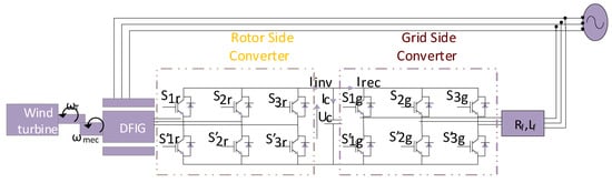
Figure 1.
WECS system.
Two voltage converters are connected via a DC bus to form the back-to-back structure. The structure depicted in the figure describes a two-level pulse width modulation (PWM) converter. The sinusoidal pulse width modulation (SPWM) (voltage references compared to a triangular carrier at switching frequencies) controls the switching of two-level three-phase back-to-back converters. The PWM generates the gate pulses for inverter switches to get inverter output voltage [26,27].
The literature is replete with descriptions of wind generator modeling. The model is given as a means of simulating the wind turbine’s behavior. The aerodynamic power taken from the turbine and transmitted to the rotor may be represented in the following way (Equation (1)) [28]:
Aerodynamic power is dependent on many factors, including Cp, the turbine’s power coefficient, the air density (1.22 kg/m2), R, the blades’ radius in meters, and V, the wind speed in meters per second. In addition, as seen in Equation (2), the power coefficient is dependent on pitch angle and tip speed ratio .
The tip speed ratio is described by Equation (3).
The generator shaft is attached to a gearbox that acts as a driver to establish the desired generator shaft speed range. Wind turbine torque and shaft speed are expressed by Equation (4).
Several papers have described in detail the DFIG’s static and dynamic modeling. It is designed using a Park dq frame model of the machine. Set Equations (5)–(8) define the voltages, flux, powers, and electromagnetic equations of the DFIG [29].
, are the stator and rotor voltages in the dq Park frame, respectively;
, are the stator and rotor flux in the dq Park frame, respectively;
, are the stator and rotor currents in the dq Park frame, respectively.
The parameters of the machine are the stator and rotor resistances (Rs and Rr, respectively) and the stator, rotor, and mutual inductances (Ls, Lr, and LM, respectively).
3. Design of Predictive Current Control
To regulate the DFIG’s output power, regulating the rotor’s currents via a side rotor converter is necessary. The controller is designed using a machine model within the Park dq framework. The stator and rotor variables are defined within the context of the stator flux reference park.
3.1. Field Orientation Strategy
When the machine is represented in a synchronous reference frame (dq), it can independently control the active and reactive stator power using direct and quadrature currents. To provide this decoupled control, it is critical to align the dq reference frame properly. The stator component d is equal to the total flux, whereas the stator component q is null. This approach enables the separation of the stator’s active and reactive power. As a result, by referring to the chosen frame, the equations describing the machine’s stator’s active and reactive power as well as the rotor voltages are determined by Equations (9) and (10), respectively.
3.2. Discrete-Time Presentation
A discrete-time (DT) illustration of the system is required to understand the system’s behavior. For this reason, it is necessary to convert the system’s continuous-time (CT) representation, presented in Equation (11), to the DT representation presented in Equation (12). This discretization is accomplished through the application of the transformation shown in Set Equation (13) [30,31,32,33]
represents the stator vector to be controlled (e.g., voltage, flux, speed, current, torque, power …).
, represents input and output vectors, respectively (e.g., voltage, current, torque).
represents the perturbation.
A, B, G represent the n*n matrices.
C represents the identity matrix.
3.3. Predictive Current Control
The overall goal of predictive model-based control is to calculate the trajectory of a future variable, manipulated to optimize the future behavior of the output. The optimization is carried out in a time-limited window by providing information about the system at the start of the temporary window. For a specific control variable, predictive control uses the system model to anticipate future process behavior; then, it achieves optimal action based on predefined optimization criteria. This strategy identifies the appropriate control variables that cancel the error between the control and reference inputs. To ensure that, the reference is set equal to the next sampling instant ; additionally, the input corrector can be written as (14):
where F is the gain matrix.
Using the above equation and Equation (12), Equation (15) is used to determine the required input.
As previously mentioned, the DFIG control must allow for independent control of the machine’s active and reactive power extraction. The inverter coupled to the rotor is responsible for ensuring this type of control.
The DFIG’s control scheme is depicted in a figure and consists of two loops. The internal loop regulates Idr and Iqr by employing predictive current controllers to track the reference determined by the external power regulation loop.
Using Equation (13), the CT representation of the system is given by Equation (16).
with .
After carrying out the required transformations to discretize the CT model, the DT model is given by Equation (17), providing the rotor voltages
With
Considering the assumption that the reference is set equal to the next sampling instant, the current references (Ird_ref and Irq_ref) are set equal to the currents at the next sampling time, Ird(k + 1) and Irq(k + 1), respectively. Given that the rotor quadrature and direct currents are proportional to the active and reactive power of the stator, respectively, the Irq ref and Ird ref are expressed as follows:
4. TESTBENCH Description
The hardware consists of a 1.5 kW doubly-fed induction generator, a 1.5 kW squirrel cage induction machine (SCIM), a Danfoss variable speed drive, a Semikron IGBT inverter, a Dspace 1104R&D, and an FPGA Nexys3 board. After designing the wind emulator, the control algorithm is applied to the DFIG rotor via the inverter. Figure 2 describes the test bench synopsis, while Figure 3 shows the actual realized test bench in the laboratory.
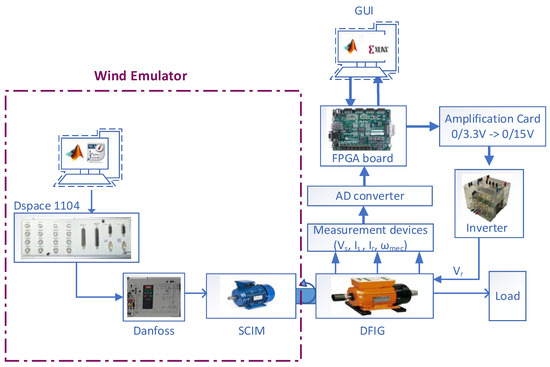
Figure 2.
Test bench synopsis.
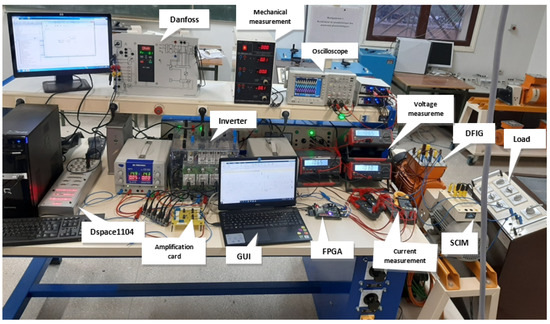
Figure 3.
Test bench.
4.1. Wind Emulator
The wind emulator is designed using a Dspace 1104 R&D board. It is an interface board that can convert Simulink blocks into machine code run on a DSP-based system. The prototyping starts with the control system’s construction using Simulink blocks, simulating the system, then running the model in real-time through the Ds1104 board. The emulator is realized through the Danfoss drive (variable speed drive) by applying the desired wind profile using the Dspace1104 board. Then this drive commands the SCIM, coupled with the DFIG, to obtain a mechanical speed that corresponds to the wind profile applied.
4.2. FPGA Implementation of Predictive Current Control
FPGAs are programmable semiconductor devices comprised of a matrix of programmable logic units connected by programmable interconnections. They are capable of implementing virtually any type of digital circuit or system. It is composed of configurable logic blocks (CLBs), which are the primary digital processing units configured to perform both combinational and sequential operations, a programmable interconnection (PI) network, configurable I/O blocks (IOBs), block RAM memories (BRAMs), digital clock management (DCM) blocks, and digital signal processor (DSP) blocks. Additionally, it includes LookUp tables (LUTs) for combinational operations and D-Flip-Flops for sequential operations. Otherwise, DSP blocks enable sophisticated arithmetic operations, while BRAM resources can be leveraged to speed up processing. The Xilinx System Generator is a toolbox for FPGA programming linked with MATLAB/Simulink that eliminates the problems associated with VHDL or Verilog programming [34]. These programming languages, which are regarded as typical methods for the implementation of FPGA-based circuits, suffer from a lack of flexibility and productivity, which is why the XSG tool was developed. One of the most significant advantages of the Xilinx system generator is the graphical user interface and the ease with which digital signal processing (DSP) algorithms may be rapidly targeted to an FPGA. This method is used to produce VHDL from a graphically constructed design [35,36].
The experimental test begins with the WECS model command being implemented via the FPGA card. After modeling the control in Matlab/Simulink, the algorithm is verified by the HDL workflow advisor to ensure that the Simulink blocks and the hardware are compatible. The HDL coder is the principal toolbox in the Simulink environment for automatically and rapidly converting the MATLAB design to equivalent HDL code for implementing the system control on the FPGA board.
Following that, control signals from the FPGA are transmitted to the inverter’s insulated gate bipolar transistor (IGBT) via an amplification card to ensure voltage adaptation (3.3–15 V). Finally, the necessary control data (voltage, current, and speed) is acquired using the appropriate measurement instruments and transferred to the FPGA via an analog to digital converter (ADC).
5. Results and Discussions
To assess the impact of the control on the system, evaluate the active and reactive power controls’ efficiency and robustness, and verify the quality of the energy produced, the wind power system was subjected to a series of simulation tests under MATLAB/SIMULINK software. In addition, experimental validation on a test bench of the predictive approach was carried out to demonstrate its efficiency.
First, a step wind profile with a zero reactive power setpoint is applied to the system.
Figure 4 shows the wind profile used. The wind is considered to be constant, with step variations at t = 30 s, t = 50 s, and t = 90 s, while Figure 5 shows the active and reactive stator power. It can be seen that the decoupling is assured between these two powers. The active power has inversely the same shape as the wind profile, which follows its reference. The active power’s negative value is explained by the fact that the machine is in generator mode. The reactive power also follows its reference. Figure 6 shows both direct and quadrature rotor current. The quadrature rotor current has the inverse of the active power shape. This result is an exception since Ps varies linearly with Irq through the negative coefficient described in Equation (18). The direct rotor current has a constant value of approximately 5 A since Qref is set equal to zero, and the remaining constant ratio φs/Lm in Equation (18) is equal to 5 A.
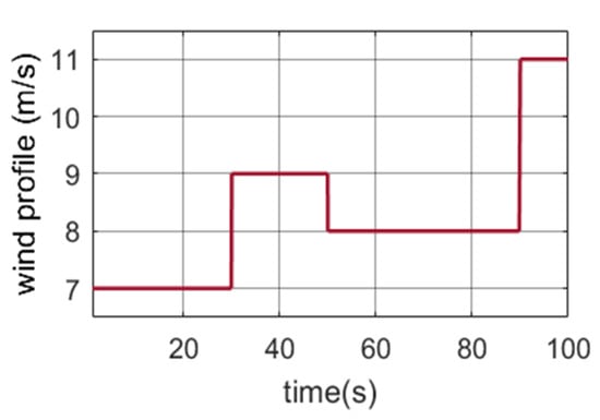
Figure 4.
Wind step profile.
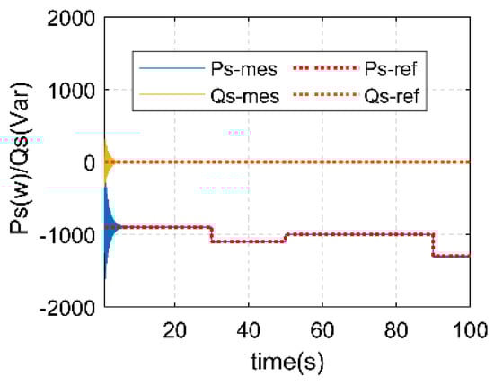
Figure 5.
Active and reactive power.
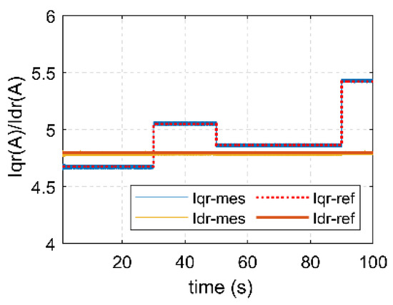
Figure 6.
Direct and quadrature rotor current.
Figure 7 shows the stator currents’ inverse shape to be identical to the wind profile, as the current image is similar to the power image. While the profile varies, the currents keep a sinusoidal shape with a period of 0.02 s, which provides 50 Hz as a frequency similar to the grid frequency. To have good quality power, the normalized value of THD needs to be less than 5%. In this study case, the THD did not exceed 0.49% (Figure 8), which testifies to excellent power quality. Regarding the rotor currents, Figure 9 shows that the profile varies sinusoidally.
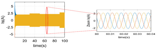
Figure 7.
Stator current.
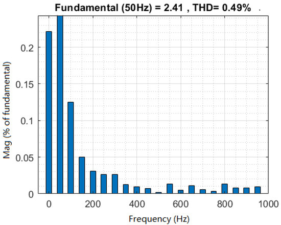
Figure 8.
THD.
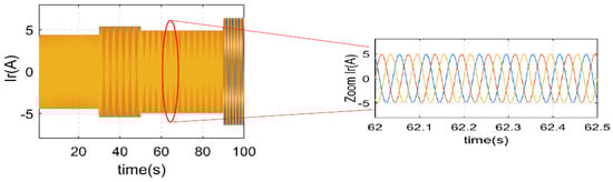
Figure 9.
Rotor current.
To illustrate the predictive control approach’s efficiency, identical condition tests are considered on the test bench. It demonstrates the system’s robustness to a step wind profile and the tracking efficiency. The figures below highlight the disparate experimental findings for a test exported from the FPGA Board.
Figure 10 shows the practical results obtained from the active and reactive power of the system between 0 and 100 s. The results appear to be consistent with those simulated. Indeed, just after starting, Qs stabilizes around zero. The power unit factor is, therefore, assured. The Ps also follows its reference inversely, as was explained in the simulation part.
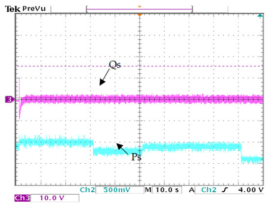
Figure 10.
Active and reactive power.
Figure 11 shows the practical results of direct and quadrature rotor current. These results are similar to those simulated: the quadrature rotor current has the inverse shape of the active power, and the direct rotor current is constant. As an exception, Irq varies linearly with Ps through the negative coefficient described in Equation (18), and Ird is found to be equal to 5 A.
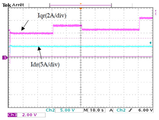
Figure 11.
Direct and quadrature rotor current.
As illustrated in Figure 12, the stator currents are sinusoidal with a constant period of 0.02 s and a frequency of 50 Hz. Regarding the rotor, currents are also sinusoidal (Figure 13). The MLI control signals applied to the converter are depicted in Figure 14. Finally, Figure 15 describes the voltage and current of a single-phase; they are in opposition, sinusoidal, and have a frequency of 50 Hz, stated in time units of 0.02 s, ensuring a unit power factor.
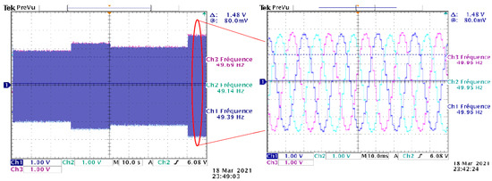
Figure 12.
Stator current.
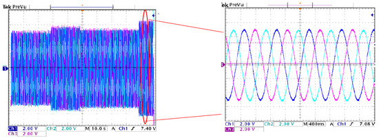
Figure 13.
Rotor current.
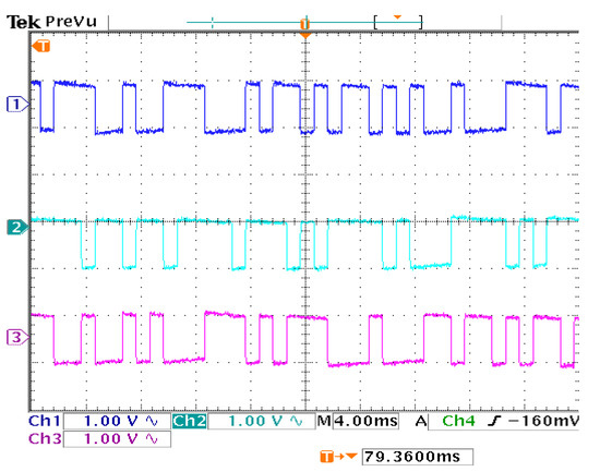
Figure 14.
MLI signals.
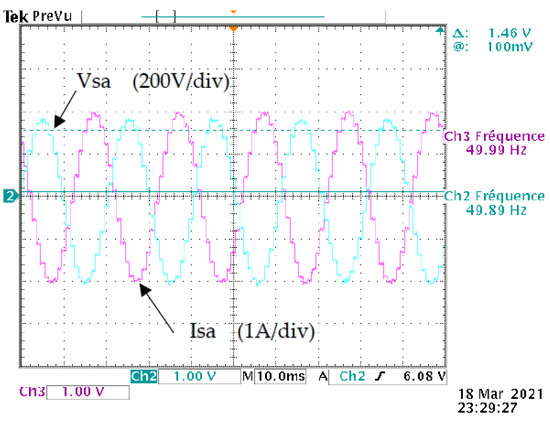
Figure 15.
Voltage and current of a phase.
6. Conclusions
This study evaluated the performance of current predictive control on a DFIG-based wind energy conversion system. Initially, the WECS and DFIG models were developed. The control was then reviewed to ensure that the WECS was performing optimally. Then, a simulation was run in the Matlab/Simulink environments to determine the performance and durability of the proposed control. A DSPACE board was used to conceptualize a wind emulator, and an FPGA board was used to create a test bench for assessing control strategies. The simulation results demonstrate that the suggested control approach can track active and reactive power references via quadrature and direct rotor current control, demonstrating the wind energy conversion system’s performance. The experimental results indicate that the system is stable and has excellent tracking performance, implying that the controller is resilient and efficient. Indeed, the experimental results appear to agree with the simulated ones. Indeed, the reactive power stabilizes around zero shortly after starting. As a result, the power unit factor is guaranteed. As was simulated, the active power similarly follows its reference inversely. The quadrature rotor current was found to be inversely proportional to the active power, whereas the direct rotor current was found to be constant. The voltage and current obtained from a single-phase were in opposition, sinusoidal, and had a frequency of 50 Hz, expressed in time units of 0.02 s.
Due to the paper’s focus on rotor control, only the hypo-synchronous mode was investigated and experimentally validated. In future research, the authors intend to go back to power injection into the grid by delving more into the hyper-synchronous mode.
Author Contributions
Conceptualization, M.B.; methodology, M.B.; software, M.B.; validation, M.B., H.A.A.; formal analysis, M.B.; investigation, M.B.; resources, M.B.; data curation, M.B.; writing—original draft preparation, M.B.; writing—review and editing, F.A.A., O.D., S.M. and M.B.; visualization, M.B.; supervision, F.A.A., O.D., S.M., B.B., A.L., M.T. and M.M.; project administration, B.B.; funding acquisition, F.A.A., O.D. and S.M. All authors have read and agreed to the published version of the manuscript.
Funding
Taif University Researchers Supporting Project (number TURSP-2020/214), Taif University, Taif, Saudi Arabia.
Acknowledgments
Authors would like to acknowledge the support from the Taif University Researchers Supporting Project (number TURSP-2020/214), Taif University, Taif, Saudi Arabia. Authors would like to thank for the support from WBI organisation (Wallonie Bruxelles Internationale).
Conflicts of Interest
The authors declare no conflict of interest.
References
- Aroussi, H.A.; Ziani, E.; Bouderbala, M.; Bossoufi, B. Improvement of direct torque control applied to doubly fed induction motor under variable speed. Int. J. Power Electron. Drive Syst. (IJPEDS) 2020, 11, 97–106. [Google Scholar] [CrossRef]
- Abad, G.; Lopez, J.; Rodríguez, M.; Marroyo, L.; Iwanski, G. Doubly Fed Induction Machine: Modeling and Control for wInd Energy Generation; John Wiley & Sons: Hoboken, NJ, USA, 2011. [Google Scholar]
- Hannan, M.; Lipu, M.H.; Ker, P.J.; Begum, R.; Agelidis, V.G.; Blaabjerg, F. Power electronics contribution to renewable energy conversion addressing emission reduction: Applications, issues, and recommendations. Appl. Energy 2019, 251, 113404. [Google Scholar] [CrossRef]
- Tarisciotti, L.; Calzo, G.L.; Gaeta, A.; Zanchetta, P.; Valencia, F.; Saez, D. A Distributed Model Predictive Control Strategy for Back-to-Back Converters. IEEE Trans. Ind. Electron. 2016, 63, 5867–5878. [Google Scholar] [CrossRef]
- Yang, X.; Liu, G.; Li, A.; Van Dai, L. A Predictive Power Control Strategy for DFIGs Based on a Wind Energy Converter System. Energies 2017, 10, 1098. [Google Scholar] [CrossRef]
- Bouderbala, M.; Bossoufi, B.; Aroussi, H.A.; Lagrioui, A.; Taoussi, M.; Ihedrane, Y.; El Ghamrasni, M. Modeling and Power Controls of Wind Energy Conversion Systems Based on Doubly Fed Induction Generator. In Proceedings of the 6th International Sustainable Energy Conference—ISEC 2018, Graz, Austria, 3–5 October 2018. [Google Scholar] [CrossRef]
- Bouchiba, N.; Barkia, A.; Sallem, S.; Alaoui, L.C.; Drid, S.; Kammoun, M.B.A. Implementation and comparative study of control strategies for an isolated DFIG based WECS. Eur. Phys. J. Plus 2017, 132, 415. [Google Scholar] [CrossRef]
- Prasad, R.M.; Mulla, M.A. Mathematical Modeling and Position-Sensorless Algorithm for Stator-Side Field-Oriented Control of Rotor-Tied DFIG in Rotor Flux Reference Frame. IEEE Trans. Energy Convers. 2019, 35, 631–639. [Google Scholar] [CrossRef]
- Nahilia, H.; Boudour, M.; Cardenas, A.; Agbossou, K.; Doumbia, M.L. Doubly fed induction wind generators model and field orientation vector control design and implementation on FPGA. Int. J. Dyn. Control. 2019, 7, 1005–1014. [Google Scholar] [CrossRef]
- Naik, K.A.; Gupta, C.P.; Fernandez, E. Design and implementation of interval type-2 fuzzy logic-PI based adaptive controller for DFIG based wind energy system. Int. J. Electr. Power Energy Syst. 2019, 115, 105468. [Google Scholar] [CrossRef]
- Marugán, A.P.; Márquez, F.P.G.; Perez, J.M.P.; Ruiz-Hernández, D. A survey of artificial neural network in wind energy systems. Appl. Energy 2018, 228, 1822–1836. [Google Scholar] [CrossRef]
- Hamasaki, S.-I.; Takaki, T.; Miyazaki, S.; Tsuji, M. Experimental verification of deadbeat control for unified power flow controller. In Proceedings of the 41st Annual Conference of the IEEE Industrial Electronics Society, Yokohama, Japan, 9–12 November 2015. [Google Scholar] [CrossRef]
- Beyene, A.M.; Haile, E.A.; Worku, G.B.; Tuka, M.B. Modeling of doubly fed induction generator based wind energy conversion system and speed controller. J. Energy Syst. 2021, 5, 46–59. [Google Scholar] [CrossRef]
- Dbaghi, Y.; Farhat, S.; Mediouni, M.; Essakhi, H.; Elmoudden, A. Indirect power control of DFIG based on wind turbine operating in MPPT using backstepping approach. Int. J. Electr. Comput. Eng. (IJECE) 2021, 11, 1951–1961. [Google Scholar] [CrossRef]
- Bouchiba, N.; Keskes, S.; Sallem, S.; Alaoui, L.C.; Drid, S.; Kammoun, M. Experimental control of a Doubly Fed Induction Generator based Wind Energy Conversion System. In Proceedings of the 2018 7th International Conference on Systems and Control (ICSC), Valencia, Spain, 24–26 October 2018; pp. 142–147. [Google Scholar] [CrossRef]
- Bossoufi, B.; Karim, M.; Taoussi, M.; Alami-Aroussi, H.; Bouderbala, M.; Deblecker, O.; Motahhir, S.; Nayyar, A.; AlZain, M.A. Rooted Tree Optimization for the Backstepping Power Control of a Doubly Fed Induction Generator Wind Turbine: dSPACE Implementation. IEEE Access 2021, 9, 26512–26522. [Google Scholar] [CrossRef]
- Boubzizi, S.; Abid, H.; El Hajjaji, A.; Chaabane, M. Comparative study of three types of controllers for DFIG in wind energy conversion system. Prot. Control. Mod. Power Syst. 2018, 3, 21. [Google Scholar] [CrossRef]
- Yang, L.; Liu, T.; Hill, D.J. Distributed MPC-based frequency control for multi-area power systems with energy storage. Electr. Power Syst. Res. 2020, 190, 106642. [Google Scholar] [CrossRef]
- Zhou, D.; Blaabjerg, F. Bandwidth oriented proportional-integral controller design for back-to-back power converters in DFIG wind turbine system. IET Renew. Power Gener. 2017, 11, 941–951. [Google Scholar] [CrossRef]
- Mazouz, F.; Belkacem, S.; Colak, I.; Drid, S.; Harbouche, Y. Adaptive direct power control for double fed induction generator used in wind turbine. Int. J. Electr. Power Energy Syst. 2019, 114, 105395. [Google Scholar] [CrossRef]
- Bossoufi, B.; Aroussi, H.A.; Boderbala, M. Direct Power Control of Wind Power Systems based on DFIG-Generator (WECS). In Proceedings of the 2020 12th International Conference on Electronics, Computers and Artificial Intelligence (ECAI), Bucharest, Romania, 25–27 June 2020. [Google Scholar] [CrossRef]
- Yaramasu, V.; Wu, B. Model Predictive Control of Wind Energy Conversion Systems; IEEE: Hoboken, NJ, USA, 2017. [Google Scholar]
- Vazquez, S.; Leon, J.I.; Franquelo, L.G.; Rodriguez, J.; Young, H.; Marquez, A.; Zanchetta, P. Model Predictive Control: A Review of Its Applications in Power Electronics. IEEE Ind. Electron. Mag. 2014, 8, 16–31. [Google Scholar] [CrossRef]
- Segovia, P.; Puig, V.; Duviella, E.; Etienne, L. Distributed model predictive control using optimality condition decomposition and community detection. J. Process. Control 2021, 99, 54–68. [Google Scholar] [CrossRef]
- Bossoufi, B.; Karim, M.; Taoussi, M.; Aroussi, H.A.; Bouderbala, M.; Motahhir, S.; Camara, M.B. DSPACE-based implementation for observer backstepping power control of DFIG wind turbine. IET Electr. Power Appl. 2020, 14, 2395–2403. [Google Scholar] [CrossRef]
- Jain, B.; Jain, S.; Nema, R. Control strategies of grid interfaced wind energy conversion system: An overview. Renew. Sustain. Energy Rev. 2015, 47, 983–996. [Google Scholar] [CrossRef]
- Alaboudy, A.K.; Daoud, A.A.; Desouky, S.S.; Salem, A.A. Converter controls and flicker study of PMSG-based grid connected wind turbines. Ain Shams Eng. J. 2013, 4, 75–91. [Google Scholar] [CrossRef]
- Charabi, Y.; Abdul-Wahab, S. Wind turbine performance analysis for energy cost minimization. Renew. Wind. Water Sol. 2020, 7, 5. [Google Scholar] [CrossRef]
- Hala, A.A.; Ziani, E.M.; Manale, B.; Badre, B. DPC & DNPC Applied To Wind Energy Converter System. In Proceedings of the 2020 5th International Conference on Renewable Energies for Developing Countries (REDEC), Marrakech, Morocco, 24–26 March 2020. [Google Scholar]
- Manale, B.; Badre, B.; Hala, A.A.; Mohammed, T.; Ahmed, L.; Petru, L. DEADBEAT Control Applied toWind Power System. In Proceedings of the 2020 5th International Conference on Renewable Energies for Developing Countries (REDEC), Marrakech, Morocco, 24–26 March 2020. [Google Scholar]
- Filho, A.J.S.; Ruppert, E. Modeling and Designing a Deadbeat Power Control for Doubly-Fed Induction Generator. Wind. Energy Manag. 2011, 113–128. [Google Scholar] [CrossRef]
- Gholami-Khesht, H.; Monfared, M. Deadbeat direct power control for grid connected inverters using a full-order observer. In Proceedings of the 2015 4th International Conference on Electric Power and Energy Conversion Systems (EPECS), Sharjah, United Arab Emirates, 24–26 November 2015. [Google Scholar] [CrossRef]
- Franco, R.; Capovilla, C.; Jacomini, R.V.; Altana, J.A.T.; Filho, A.J.S. A deadbeat direct power control applied to doubly-fed induction aerogenerator under normal and sag voltages conditions. In Proceedings of the IECON 2014 40th Annual Conference of the IEEE Industrial Electronics Society, Dallas, TX, USA, 29 October–1 November 2014. [Google Scholar] [CrossRef]
- Bonny, T. Chaotic or Hyper-chaotic Oscillator? Numerical Solution, Circuit Design, MATLAB HDL-Coder Implementation, VHDL Code, Security Analysis, and FPGA Realization. Circuits Syst. Signal Process. 2020, 40, 1061–1088. [Google Scholar] [CrossRef]
- Naik, R.L.; Ieee, M. FPGA Based Implementation of Symmetrical Switching in SVPWM for Three Level NPC Converter. In Proceedings of the 3rd International Conference on Inventive Systems and Control (ICISC 2019), Coimbatore, India, 10–11 January 2019; pp. 592–597. [Google Scholar]
- Moussa, I.; Bouallegue, A.; Khedher, A. 3 kW wind turbine emulator implementation on FPGA using matlab/simulink. Architecture 2015, 5, 1154–1163. [Google Scholar] [CrossRef]


Publisher’s Note: MDPI stays neutral with regard to jurisdictional claims in published maps and institutional affiliations. |
© 2021 by the authors. Licensee MDPI, Basel, Switzerland. This article is an open access article distributed under the terms and conditions of the Creative Commons Attribution (CC BY) license (https://creativecommons.org/licenses/by/4.0/).