Article

Control Methods for Performance Improvement of an Integrated On-Board Battery Charger in Hybrid Electric Vehicles

1
Department of Electrical Energy Engineering, Keimyung University, Daegu 42601, Korea
2
R&D Center, ADT Co., Ltd., Anyang 14059, Korea
*
Author to whom correspondence should be addressed.
Electronics 2021, 10(20), 2506; https://doi.org/10.3390/electronics10202506
Submission received: 14 September 2021 / Revised: 8 October 2021 / Accepted: 13 October 2021 / Published: 14 October 2021
(This article belongs to the Special Issue High-Power Density Multilevel Inverter/Converter System)

Abstract

:
This paper presents control methods for performance improvement of an integrated on-board battery charger (OBC) in hybrid electric vehicles (HEVs). HEVs generally consist of an OBC and a starter generator system (SGS). Since these each have a power conversion device for independent operation, such as battery charging and starter generator driving for engine starting, it necessarily increases the number of components, weight, and volume of the HEV. In order to overcome these disadvantages, recent research concerning the integrated OBC has progressed. Although it demands installation of power relays and an additional circuit, the integrated OBC is effectively operated for battery charging and starter generator driving. This paper proposes not only a harmonic reduction method of grid current, but also a feed-forward control method for performance improvement of the integrated OBC in HEVs. The effectiveness of the proposed control methods is verified by simulation and experimental results.

1. Introduction

Research concerning hybrid electric vehicles (HEVs) has been steadily growing with development of vehicular batteries. HEVs are able to replace internal combustion engine (ICE)-powered vehicles with comparable high driving efficiency and low exhaust emission. A HEV utilizes both electrical and mechanical energy to drive the vehicle, contrary to the conventional ICE powered vehicle [1,2,3,4,5]. In addition, a HEV is considered not only a form of transportation but also a portable energy storage device. It can be connected to a grid source to effectively use electrical energy stored in the battery. In other words, an HEV can be operated as vehicle-to-grid (V2G) by flowing electrical energy from the vehicle to the grid, and vice versa, grid-to-vehicle (G2V), by using various control methods [6,7,8,9], thus providing bidirectional power flow.
Along with HEV development, interest in the issue of battery charge has increased research in power conversion devices and control strategies of battery chargers for HEVs and electric vehicles (EV) [10,11,12]. Furthermore, recently, interest in the performance improvement and safety issues related to battery charge has increased. The control strategy with feed-forward to improve the dynamic characteristic of battery chargers is proposed in [13], and methods for safety improvement by wide output voltage range or voltage drop compensation of the battery charger for HEVs and EVs are proposed [14,15].
Recently, from the point of view of the entire battery charge system, interest in the issue of the battery management system (BMS) has increased. The purpose of the BMS is to manage the battery and various functions for the BMS, which are classified as real-time monitoring, calculation and prediction, protection, and optimization, which are under development to improve reliability and safety of battery charging [16,17,18,19,20,21].
In the HEV, a number of components are required to drive the vehicle using both electrical and mechanical energy. Above all, an on-board battery charger (OBC) and a starter generator system (SGS) are separately used for the HEV. The OBC is necessary for battery charging the HEV by using the grid source commonly provided in households and various control methods for OBC, including battery charging methods that have been widely researched [22,23,24,25]. The SGS is composed of a drive inverter with a starter generator. It is necessary for engine starting from an idle stop and to increase driving efficiency of HEVs. In other words, its role is mainly classified into two parts. First, the SGS converts the mechanical energy, such as kinetic energy of the HEV, into the electrical energy for battery charging. Second, it relieves exhaust emission in case the HEV is stopped briefly while driving in downtown [26,27,28].
Since the OBC and the SGS each have a power conversion device for independent operation, such as battery charging and a generator for starting the engine, it necessarily increases the number of components, weight, and volume of the HEV. In order to overcome these disadvantages by eliminating the conventional OBC from an HEV, research into an integrated OBC has recently progressed [29,30,31,32]. In case the integrated OBC proposed in [29,30,31,32] is operated in the battery charging mode, windings of the starter generator are used as a filter inductor of the grid source. As a result, by reducing the number of power conversion devices using the integrated OBC, more interior space is obtained and the manufacturing cost of the HEV is reduced.
Contrary to the integrated OBC presented in other research, this paper proposes an integrated OBC using the windings of the starter generator as a filter inductor of the DC–DC converter. In addition, since the integrated OBC operated for battery charging is connected to the grid source, control methods for performance improvement such as power quality and high system stability are required. Therefore, this paper introduces a configuration of the integrated OBC; in addition, we propose not only a harmonic reduction method of grid current, but also a feed-forward control method for performance improvement of the integrated OBC. The effectiveness of the proposed control methods is verified by simulation and experimental results.

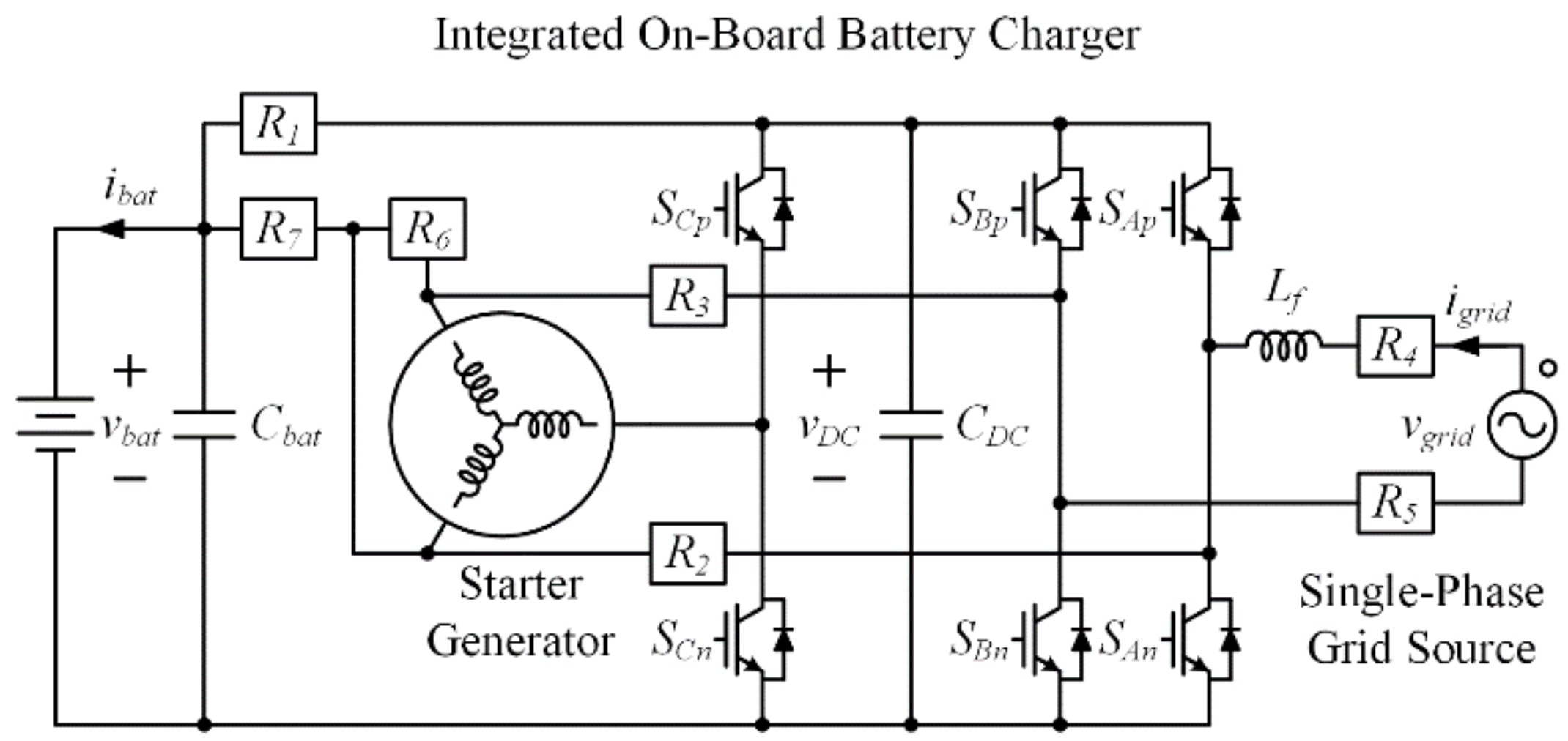
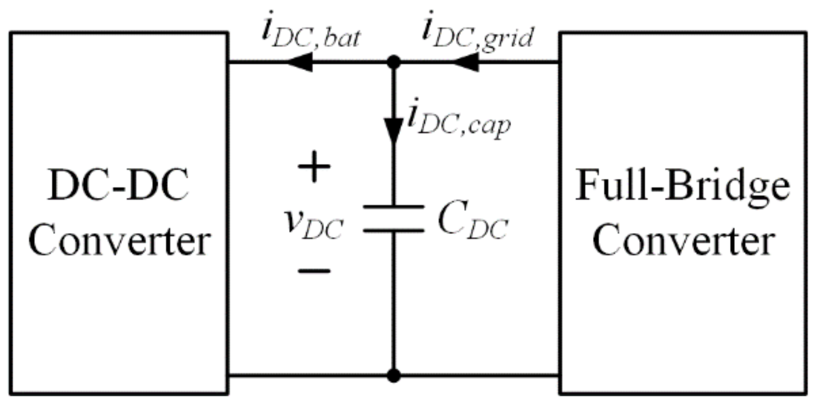
2. Configuration of Integrated OBC

Figure 1 shows the circuit diagram of the integrated OBC. The integrated OBC is constructed by installing seven power relays (R1R7), a filter inductor (Lf) with a single-phase grid source, and an additional circuit in the conventional SGS. By modifying its circuit depending on operation with turn-on and turn-off of R1R7, as listed in Table 1, it can be operated in battery charging mode and starter generator driving mode, similar to the conventional OBC and the SGS, respectively. The operation of R1R7 to determine the operation modes of the integrated OBC is implemented after power flow is stopped.
The integrated OBC decreases the number of power conversion devices and their components, weight, and volume, when compared with an HEV using the conventional OBC and the SGS separately [33]. As listed in Table 2, the volume required to contain each power conversion device for the OBC and the SGS in the conventional HEV is about 7.42 L. However, although power relays are added in the integrated OBC, the volume required to contain the integrated OBC is decreased by up to 4.65 L, which is about 37% smaller, because the volume for IGBT modules, gate drivers, and heatsink used in the integrated OBC is decreased considerably. Therefore, the integrated OBC is able to improve the power density of the HEV.

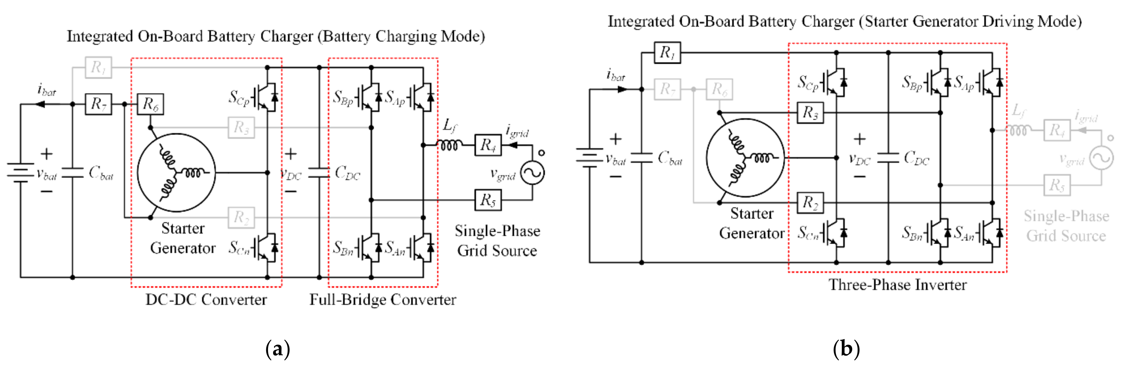
2.1. Battery Charging Mode

In order to operate the integrated OBC in the battery charging mode, as shown in Figure 1, R1R3 are turned off, simultaneously, and R4R7 are turned on. Through this operation of power relays, the integrated OBC is reconfigured with the single-phase grid source, a full-bridge converter, a DC–DC converter, and a battery, as shown in Figure 2a.
The single-phase grid source is connected to the full-bridge converter, which is composed of four switches (SAp, SAn, SBp, and SBn), using R4 and R5. AC power generated from the single-phase grid source is converted into DC voltage and current in a DC-link by the full-bridge converter. In addition, contrary to the integrated OBC proposed in [29,30,31,32], the windings of the starter generator are used as the filter inductor of the DC–DC converter, which is composed of two switches (SCp and SCn). Therefore, an equivalent inductance regarding the filter inductor of the DC–DC converter is 1.5 times of that regarding the single-winding of the starter generator. Finally, the DC–DC converter is connected to the battery by using R6 and R7 for battery charging with voltage and current control. In this battery charging mode, the integrated OBC can be operated with the bidirectional power flow for V2G and G2V depending on reference current for the current control using the DC–DC converter.
The rated current of the starter generator needs to be considered to assure that the current flowing into the windings in battery charging mode will not exceed the rated current. In addition, the current flowing into the single-winding (La) connected to SCp and SCn, shown in Figure 2a, is evenly split between the other windings (Lb and Lc) of the starter generator. Due to the unbalanced current of the windings, the heat is not even and this issue needs to be considered. However, the starter generator has a large rated current and the single-winding connected to SCp and SCn is randomly decided as one of La, Lb, or Lc due to starter generator driving. Therefore, in the long term, the unbalanced current of the windings resulting in the uneven heat does not significantly affect the feasibility of the starter generator. Furthermore, current balancing techniques with partial modification of the circuit [34,35] and selection method of the single-winding connected to SCp and Scn based on thermal modeling [36] can be applied to solve the problem caused by the unbalanced current of the windings.

2.2. Starter Generator Driving Mode

In contrast to the battery charging mode, R1R3 are turned on, simultaneously, R4R7 are turned off in order to operate the integrated OBC, as shown in Figure 1, in the starter generator driving mode. Through this operation of power relays, the integrated OBC is reconfigured with the battery, a three-phase inverter, and the starter generator, as shown in Figure 2b.
The battery is connected to the DC-link of the three-phase inverter, which is composed of all switches of the integrated OBC, using R1 in order to apply DC power stored in the battery to the DC-link. DC power applied to the DC-link is converted into AC voltage and current by the three-phase inverter. Additionally, the three-phase inverter is connected to the starter generator using R2 and R3 in order to drive the starter generator using converted AC voltage and current. The circuit diagram and operation principle of the integrated OBC operated in the starter generator driving mode are equal to those of the conventional SGS.
As a result, although the integrated OBC demands additional installation in the conventional SGS, it is effectively operated for battery charging and starter generator driving depending on operation of the power relays.

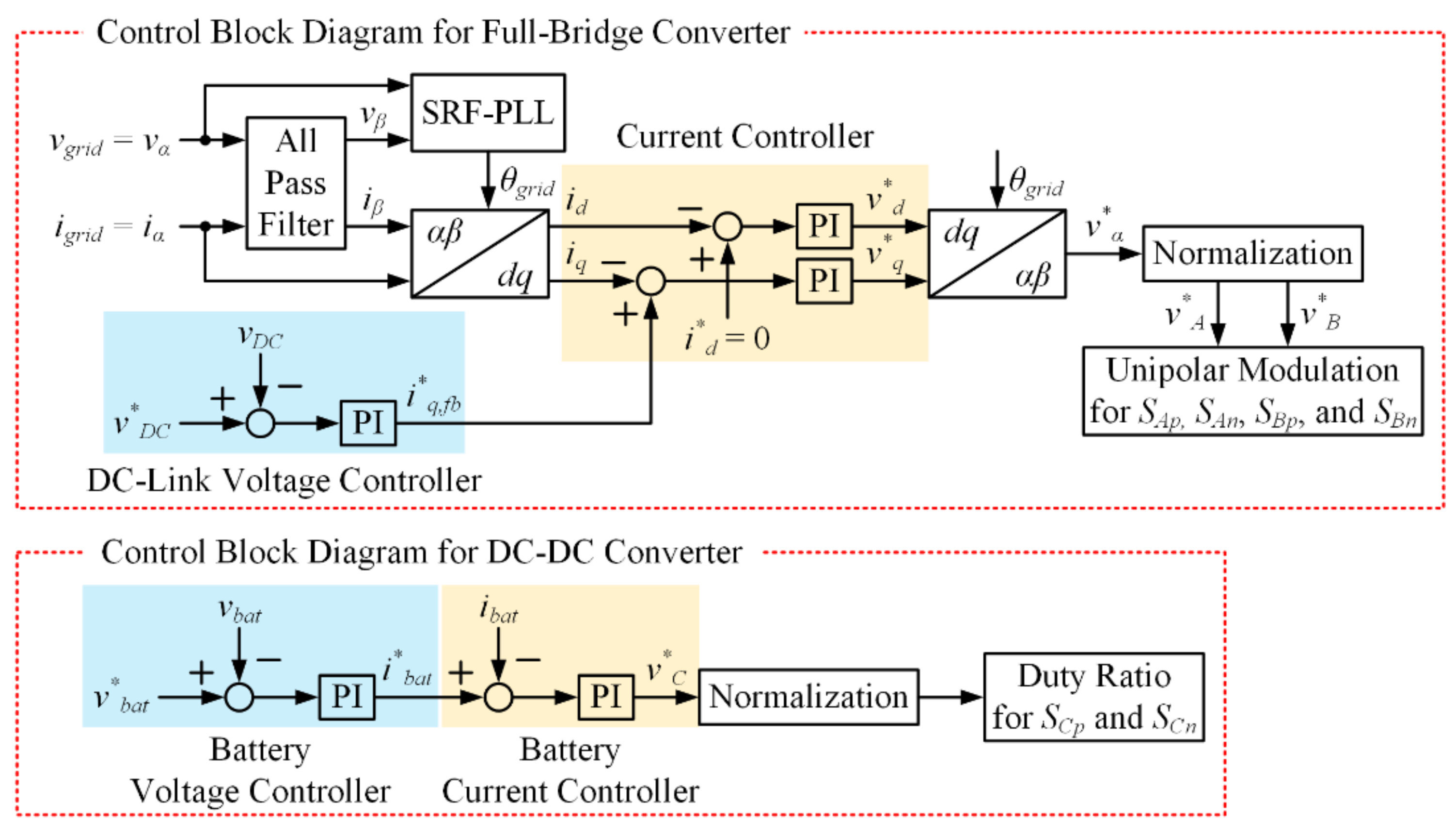
3. Control Methods in Battery Charging Mode

In this paper, control methods of the integrated OBC operated in the battery charging mode are only considered except the control methods in the starter generator driving mode, which are similar to those of the common three-phase inverter to drive electric machines. The integrated OBC operated in the battery charging mode, as shown in Figure 2a, is mainly composed of the full-bridge converter and the DC–DC converter using the windings of the starter generator as the filter inductor. Therefore, their control methods are classified into two parts: control block diagrams for the full-bridge converter and the DC–DC converter, as shown in Figure 3.

3.1. Control Method of Full-Bridge Converter

The full-bridge converter in the integrated OBC operated in the battery charging mode performs AC–DC power conversion using a single-phase grid source with a DC-link voltage controller and current controller. In the control block diagram for the full-bridge converter, voltage (vgrid) and current (igrid) of the single-phase grid source are defined to α-axis voltage (vα) and current (iα) in the stationary reference frame. β-axis voltage (vβ) and current (iβ) are obtained by using an all-pass filter (APF), which is expressed as in (1), because APF calculates only a 90-degree phase-delayed signal compared with input signal, thus keeping the amplitude constant.
G A P F s = s ω A P F s + ω A P F .
Additionally, vα and vβ are used to obtain a phase angle (θgrid) of the single-phase grid source with synchronous reference frame phase-locked loop (SRF-PLL) [37]; iα and iβ are converted to d–q axis current (id and iq) in the synchronous reference frame using the θgrid.
In the DC-link voltage controller, DC-link voltage (vDC) is controlled to reference DC-link voltage (v*DC) using a proportional–integral (PI) controller [38], and the output of DC-link voltage controller is expressed as in (2).
i q , f b * = K p , V C v D C * v D C + K i , V C s v D C * v D C ,
where Kp,VC and Ki,VC are proportional and integral gain of DC-link voltage controller, respectively. In current controller, d-axis reference current (i*d) is set to zero and q-axis reference current is set to i*q,fb; id and iq are controlled to i*d and i*q,fb using the PI controller, respectively, and the outputs of current controller are expressed as in (3).
v d * = K p , C C i d * i d + K i , C C s i d * i d v q * = K p , C C i q , f b * i q + K i , C C s i q , f b * i q
where Kp,CC and Ki,CC are proportional and integral gain of current controller, respectively. Voltages v*d and v*q are converted to αβ axis reference voltages (v*α and v*β) using the θgrid; among them, v*α is only used to operate the full-bridge converter. Finally, an unipolar modulation method is used to operate SAp, SAn, SBp, and SBn of the full-bridge converter to obtain the adequate current, which has low total harmonic distortion (THD) and less ripple component.

3.2. Control Method for the DC–DC Converter

The DC–DC converter in the integrated OBC operated in the battery charging mode uses the windings of the starter generator as the filter inductor. It performs DC–DC power conversion between the DC-link and the battery with battery voltage and current controller. In the constant voltage (CV) mode of the DC–DC converter, voltage (vbat) and current (ibat) of the battery are controlled to reference voltage and current (v*bat and i*bat) using the PI controller. Furthermore, in the constant current (CC) mode, the battery current controller is only used. The output of battery voltage and current controller is expressed as in (4).
i b a t * = K p , B V C v b a t * v b a t + K i , B V C s v b a t * v b a t v C * = K p , B C C i b a t * i b a t + K i , B C C s i b a t * i b a t
where Kp,BVC, Ki,BVC, Kp,BCC, and Ki,BCC are proportional and integral gains of battery voltage and current controller, respectively. The duty ratio for SCp and SCn is determined by v*C as the output of battery current controller.

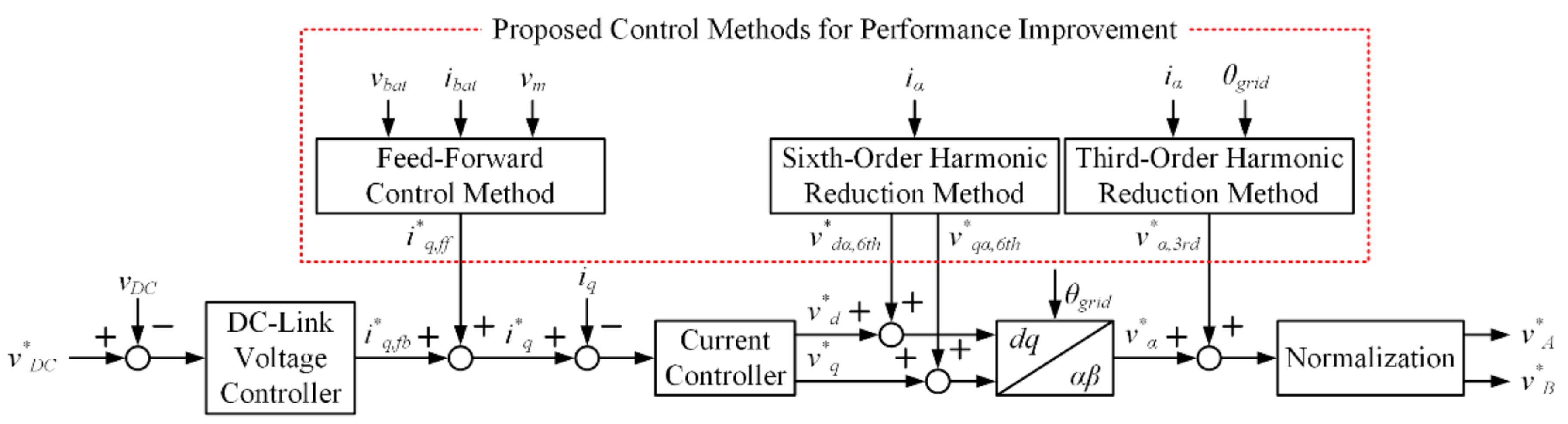
4. Proposed Control Methods for Performance Improvement of Integrated OBC

In the integrated OBC operated in the battery charging mode, harmonic components included in igrid deteriorate power quality, operation efficiency, and performance of the integrated OBC and cause unstable control of the full-bridge converter and a shorter lifetime of the elements. Therefore, additional control methods are required for performance improvement such as power quality and high system stability. This paper proposes not only the harmonic reduction method of grid current but also the feed-forward control method.

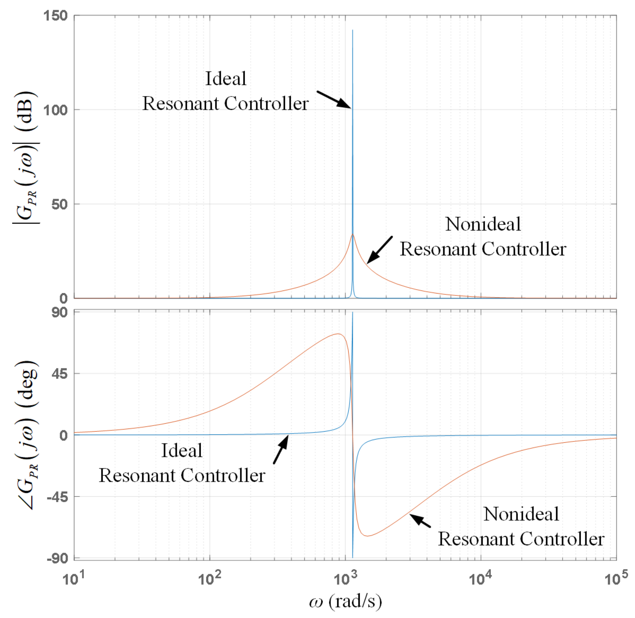
4.1. Reduction Method of the Third-Order Harmonic Component

The third-order harmonic component is essentially included in igrid because the single-phase grid source is used in the integrated OBC [39]. A nonideal proportional-resonant (PR) controller is used to reduce the third-order harmonic component; its transfer function is expressed as in (5).
G P R s = K p , P R + 2 K r , P R ω c s s 2 + 2 ω c s + ω r 2 ,
where Kp,PR and Kr,PR are proportional and resonant gain of the nonideal PR controller; ωc and ωr are the cutoff frequency and resonant frequency, respectively [40,41,42]. The nonideal PR controller is able to control igrid in a specific frequency band selectively and it is a reasonable method to reduce the third-order harmonic component, which is close to the fundamental component of igrid due to its narrow frequency bandwidth, as shown in Figure 4.

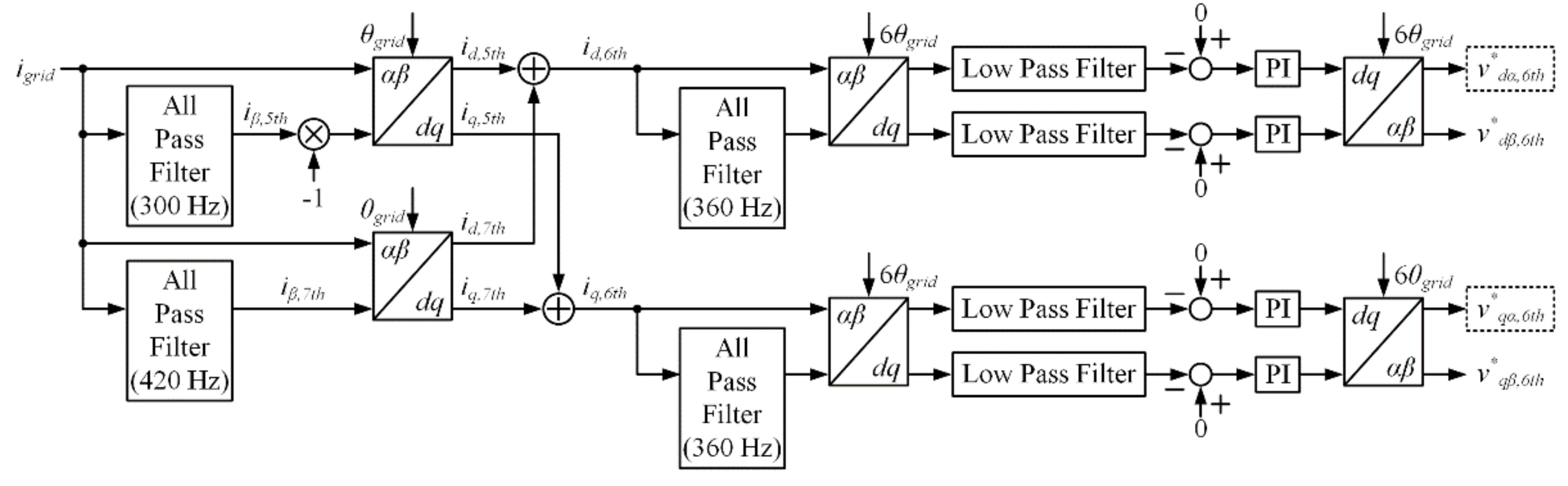
4.2. Reduction Method of the Sixth-Order Harmonic Component

Fifth-order and seventh-order harmonic components are also included in igrid due to distortion of vgrid caused by nonlinear characteristics of switching devices and effect on dead-time in the full-bridge converter. Additionally, vgrid ideally occurs in the form of a sinusoidal wave; however, fifth-order and seventh-order harmonic components are included in nonideal vgrid. These components are also influenced on fifth-order and seventh-order harmonic components of igrid.
Generally, iα and iβ are expressed by Fourier transform as in (6), and it includes not only the fundamental component of igrid but also fifth-order and seventh-order harmonic components.
i α = I m sin ω g r i d t + 1 5 sin 5 ω g r i d t + 1 7 sin 7 ω g r i d t + i β = I m cos ω t + 1 5 cos 5 ω g r i d t 1 7 cos 7 ω g r i d t +
where Im is magnitude of igrid and ωgrid is angular frequency of the single-phase grid source. Additionally, id and iq are expressed by coordinate transformation to the synchronous reference frame of iα and iβ as in (7).
i d = I m 1 5 sin 6 ω g r i d t + 1 7 sin 6 ω g r i d t + i q = I m 1 + 1 5 cos 6 ω g r i d t 1 7 cos 6 ω g r i d t +
As a result, fifth-order and seventh-order harmonic components included in iα and iβ as in (6) are converted to sixth-order harmonic components in id and iq as in (7). Therefore, it is possible to reduce fifth-order and seventh-order harmonic components of igrid through the control of sixth-order harmonic components.
Figure 5 shows the control block diagram for reduction of sixth-order harmonic components. Fifth-order (id,5th and iq,5th) and seventh-order harmonic components (id,7th and iq,7th) of igrid in the synchronous reference frame can be obtained by using APFs with bandwidths of 300 and 420 Hz, and coordinate transformation to the synchronous reference frame with θgrid. The sum of id,5th and id,7th and the sum of iq,5th and iq,7th are sixth-order harmonic components (id,6th and iq,6th), respectively. In addition, APFs with bandwidth of 360 Hz and coordinate transformation to the synchronous reference frame with 6θgrid are used for id,6th and iq,6th. Finally, reference voltages (v*dα,6th and v*qα,6th) for reduction of sixth-order harmonic components of igrid can be obtained by regulating the outputs of the coordinate transformation to be zero by using the PI controller.

4.3. Feed-Forward Control Method

The full-bridge converter connected to the single-phase grid source in the integrated OBC regulates DC-link voltage regardless of operation of the DC–DC converter that regulates vbat or ibat for battery charging at the sacrifice of DC-link voltage fluctuation. However, in case the power of the battery-side in the integrated OBC is abruptly changed, the DC-link voltage will fluctuate greatly, causing a performance deterioration of the integrated OBC. Since DC-link voltage fluctuation at transient condition is generated by current (iDC,cap) flowing into DC-link capacitor (CDC) in the integrated OBC, it can be reduced by using the fundamental concept that iDC,cap is regulated to be zero with the proposed feed-forward control method.
Figure 6 shows the block diagram of the integrated OBC with DC-link current flow. If current (iDC,grid) flowing into the DC-link from the single-phase gird-source with the full-bridge converter is made equal to that (iDC,bat) flowing into the battery-side with the DC–DC converter from the DC-link, iDC,cap does not flow into DC-link capacitor and DC-link voltage does not fluctuate.
In the integrated OBC, iDC,grid and iDC,bat are expressed as in (8).
i D C , g r i d = P g r i d v D C , i D C , b a t = P b a t v D C ,
where Pgrid and Pbat are power of the single-phase grid source and battery-side, respectively, which are expressed as in (9), neglecting the losses of the integrated OBC.
P g r i d = 1 2 × v m × i m = 1 2 × v α 2 + v β 2 × i α 2 + i β 2 P b a t = v b a t × i b a t
where vm and im are magnitudes of vgrid and igrid. Substituting (9) into (8), iDC,grid and iDC,bat are expressed as in (10).
i D C , g r i d = P g r i d v D C = 1 2 v D C × v m × i m i D C , b a t = P b a t v D C = v b a t × i b a t v D C
where iDC,cap is expressed as in (11) depending on Kirchhoff’s current law to DC-link capacitor node; additionally, it should be regulated at zero in order to reduce DC-link voltage fluctuation.
i D C , c a p = i D C , g r i d i D C , b a t = 1 2 v D C × v m × i m v b a t × i b a t v D C = 0
From (11), im equals iq because id is controlled at zero using the full-bridge converter in the integrated OBC. It is represented as in (12).
v m × i q 2 v D C = v b a t × i b a t v D C , v m × i q = 2 × v b a t × i b a t .
As a result, i*q,ff as the feed-forward component to reduce DC-link voltage fluctuation at transient condition is expressed as in (13).
i q , f f * = 2 × v b a t × i b a t v m = 2 × P b a t v m .
In the integrated OBC operated in the battery charging mode, consequently, the proposed feed-forward control method can effectively reduce DC-link voltage fluctuation under a transient condition, including the case when the battery-side power is abruptly changed.
Figure 7 shows the control block diagram of the proposed control method for performance improvement of the integrated OBC. Firstly, i*q,ff obtained by the feed-forward control method is added to i*q,fb to set a novel q-axis reference current (i*q) for current controller of the full-bridge converter. Secondly, v*dα,6th and v*qα,6th obtained by the reduction method of sixth-order harmonic components are added to v*d and v*q as outputs of current controller, respectively. Finally, v*α,3rd obtained by the reduction method of third-order harmonic components is added to v*α for the unipolar modulation of the full-bridge converter.
As a result, through the proposed control methods, such as the reduction methods of harmonic components included in igrid and the feed-forward control method in the integrated OBC operated in the battery charging mode, performance improvement can be achieved, such as power quality and high system stability at transient condition.

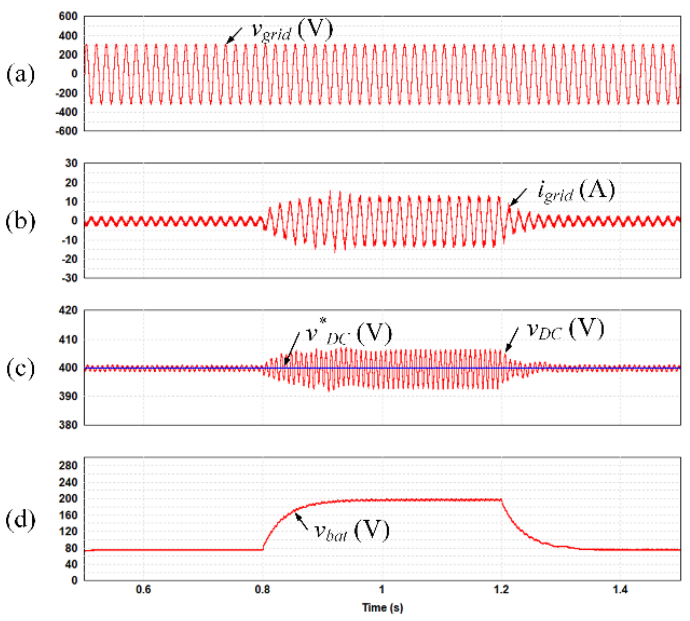
5. Simulation Results

In order to demonstrate the validity of the proposed control methods for the integrated OBC operated in the battery charging mode, as shown in Figure 2a, simulation was performed using PSIM software. In Figure 2a, the single-phase grid source is 220 Vrms/60 Hz and Lf is set to 4 mH. In the DC-link of the integrated OBC, CDC is set to 2000 µF considering second-order ripple component of the DC-link current. The single-winding inductance of the starter generator is 0.605 mH; therefore, the equivalent inductance regarding the filter inductor of the DC–DC converter is set to 0.9075 mH, which is 1.5 times that of the single-winding inductance. In addition, the battery is replaced by a load resistor; detailed simulation parameters are given in Table 3.
Figure 8 shows the simulation results of the integrated OBC operated in battery charging mode. In Figure 8a, vgrid is 220 Vrms/60 Hz as a sinusoidal waveform without harmonic components. As shown in Figure 8c,d, vDC and vbat are controlled to v*DC and v*bat, which are set to 400 and 140 V, using the full-bridge converter and the DC–DC converter, respectively. However, the third-order harmonic component is included in igrid, as shown in Figure 8b, due to the single-phase grid source used in the integrated OBC; it can be confirmed by the FFT spectrum of igrid, as shown in Figure 8e.
Figure 9 shows the simulation results of the integrated OBC with fifth-order and seventh-order harmonic components in the single-phase grid source. It has the same scenario as that shown in Figure 8; however, fifth-order and seventh-order harmonic components, which are set to 15% and 10% of fundamental magnitude in vgrid, are included in vgrid, as shown in Figure 9a. Therefore, although vDC and vbat are controlled to v*DC and v*bat as shown in Figure 9c,d, igrid is distorted by harmonic components as shown in Figure 9b. Figure 9e shows the FFT spectrum of igrid. Comparing with that of Figure 8e, fifth-order and seventh-order harmonic components in igrid are increased.
Figure 10 shows the simulation results of the integrated OBC with the proposed reduction method of third-order and sixth-order harmonic components. It has the same scenario as that shown in Figure 9, including fifth-order and seventh-order harmonic components in the single-phase grid source, as shown in Figure 10a. Contrary to that of Figure 9, however, harmonic components included in igrid are reduced by using the proposed reduction method of third-order and sixth-order harmonic components, as shown in Figure 10b. In the FFT spectrum of igrid, as shown in Figure 10e, it can be confirmed that the harmonic components are reduced.
Figure 11 shows the simulation results of the integrated OBC without the proposed feed-forward control method in case the power of the battery-side is abruptly changed. In this simulation, to abruptly change the power of the battery-side, ibat is changed to 10 A from 4 A at 0.8 s. In addition, it is also changed to 4 A from 10 A at 1.2 s. Therefore, vDC fluctuates greatly and it causes a performance deterioration of the integrated OBC.
Figure 12 shows the simulation results of the integrated OBC with proposed feed-forward control method in case the power of the battery-side is abruptly changed. It has the same scenario as that of Figure 11. However, as shown in Figure 12c, vDC does not fluctuate at 0.8 and 1.2 s when the power of the battery-side is abruptly changed by using the proposed feed-forward control method. As a result, it can effectively reduce fluctuation of vDC at transient condition through the proposed feed-forward control method.

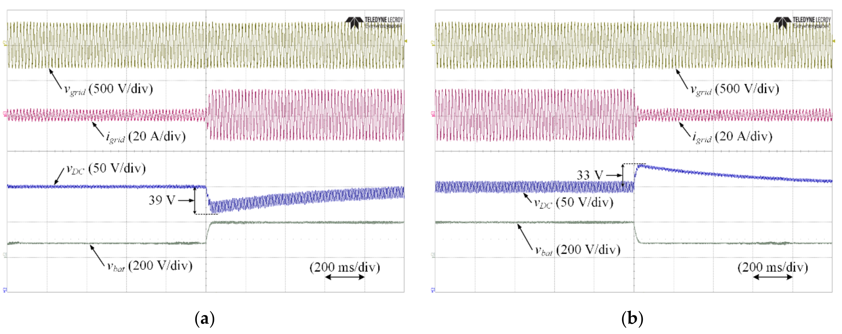
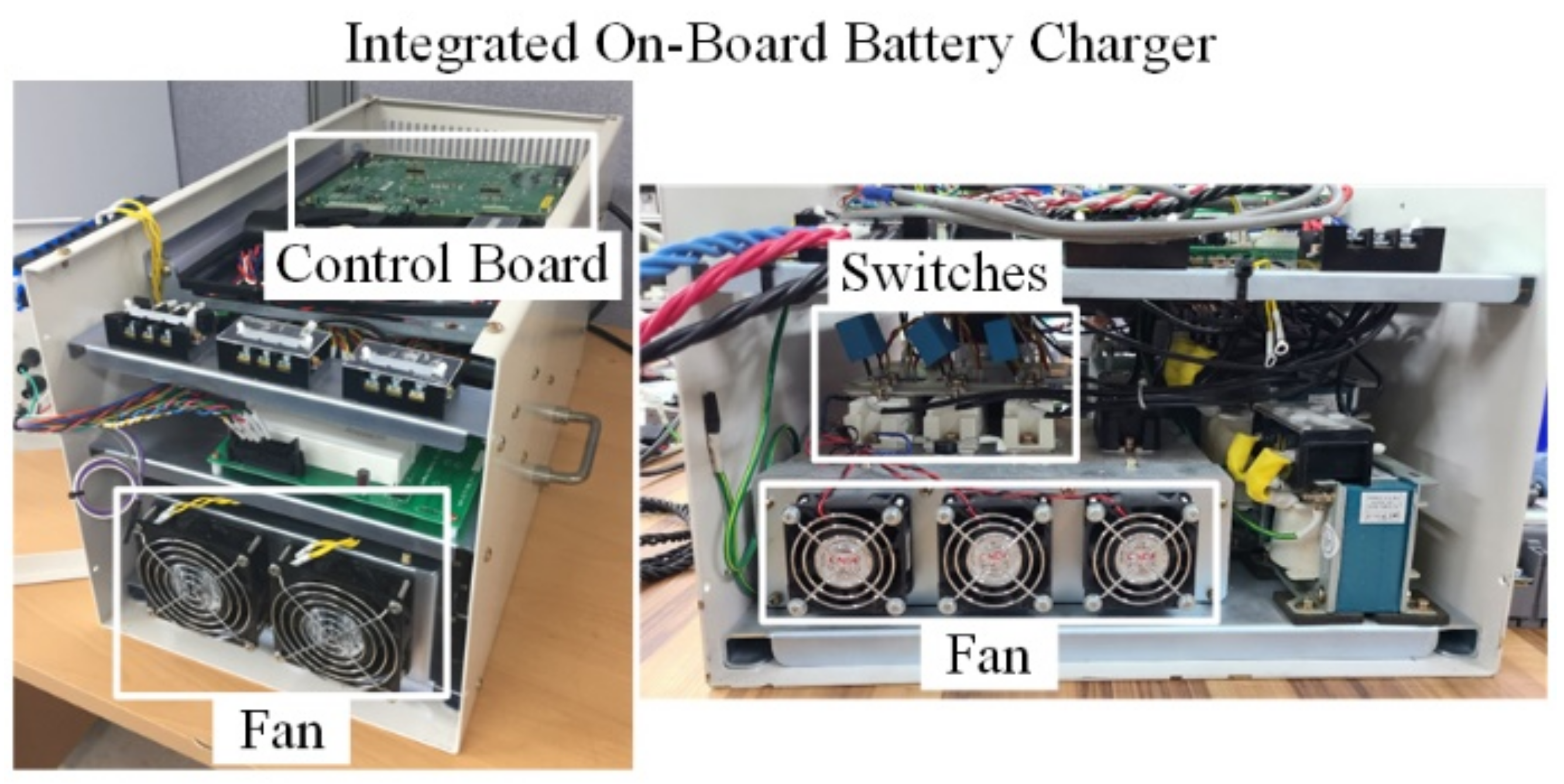
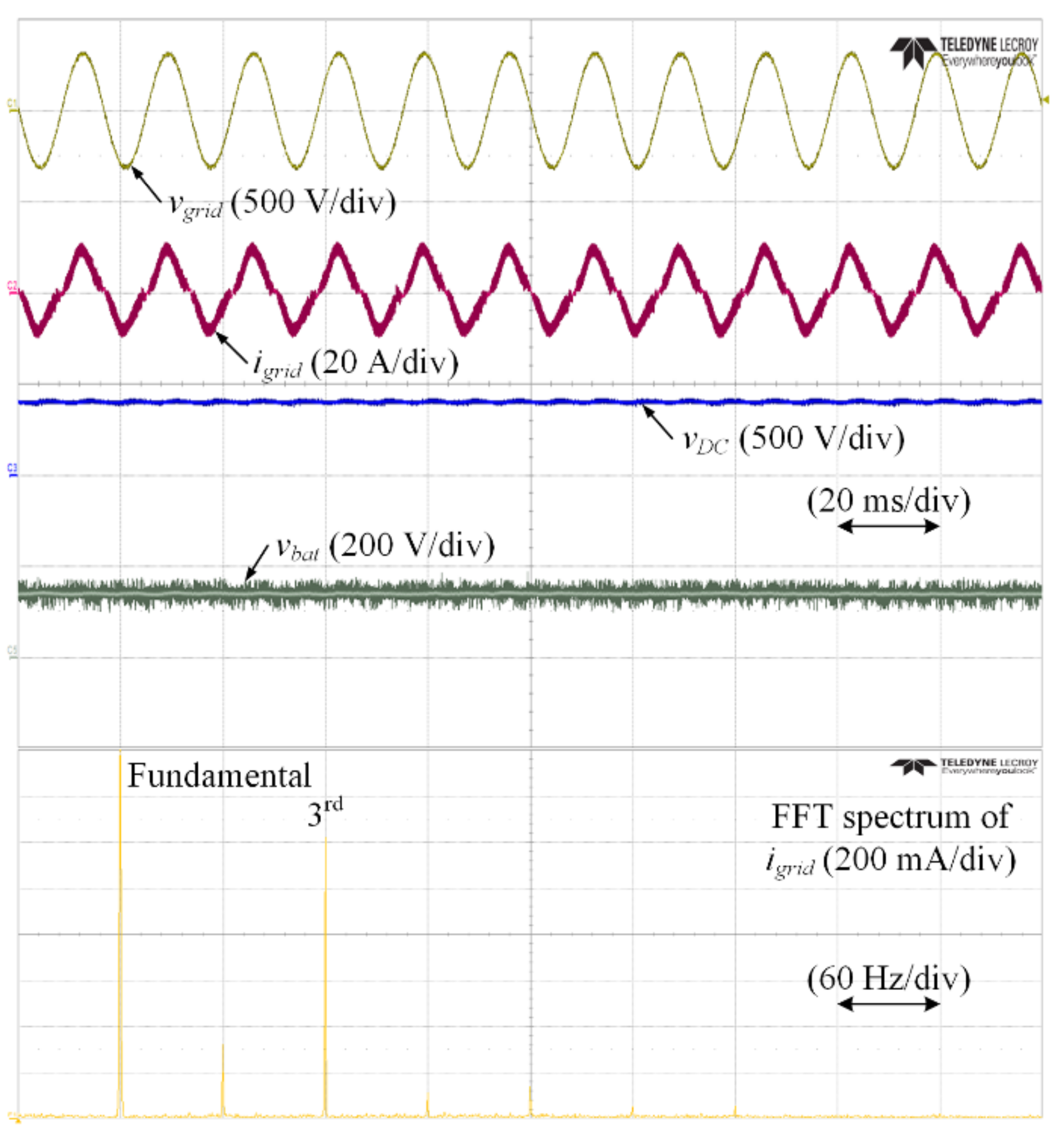
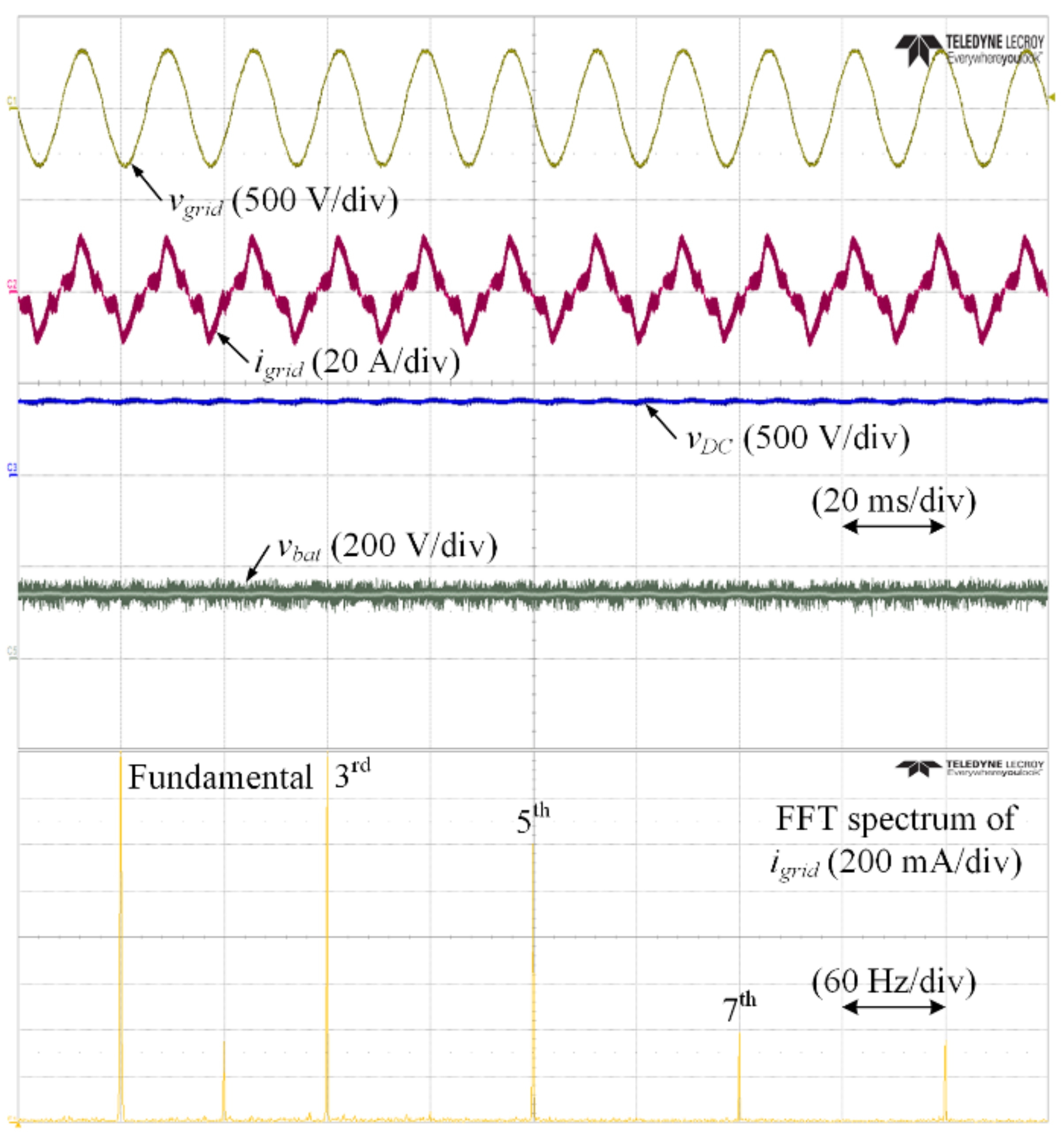
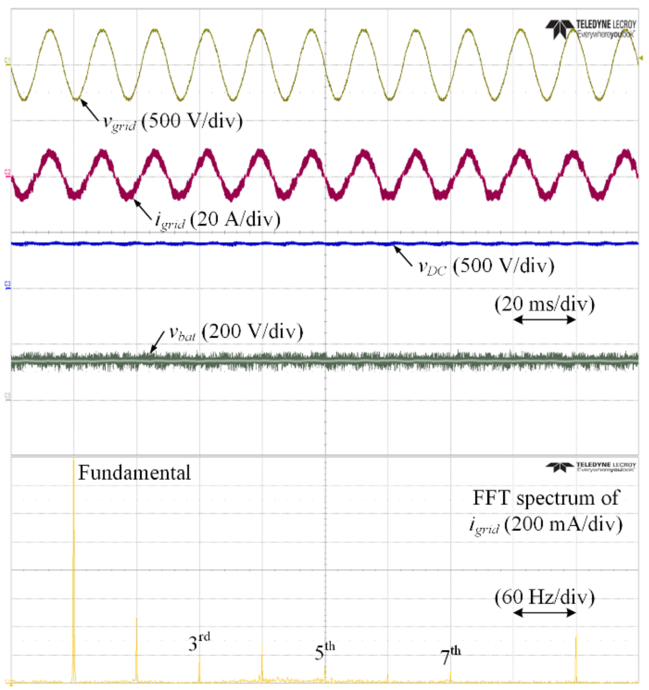
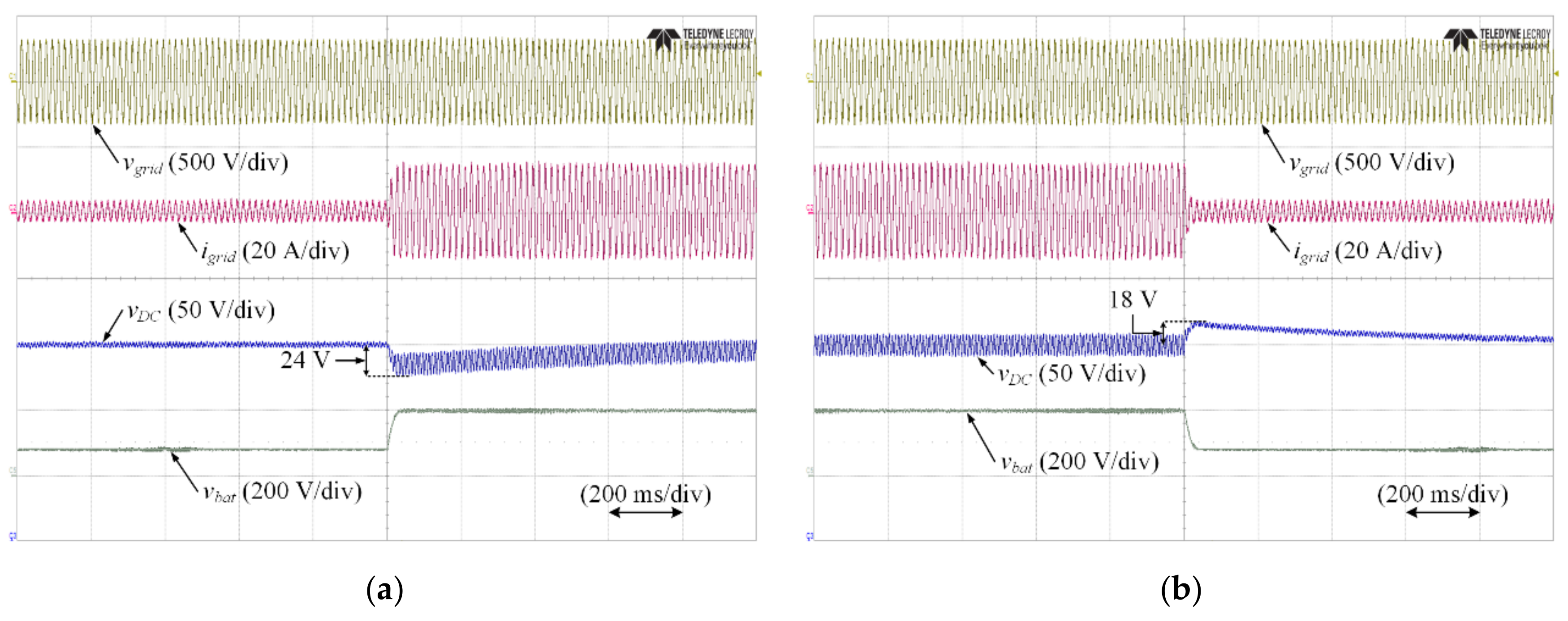
6. Experimental Results

To demonstrate the validity of the proposed control methods for the integrated OBC, experiments were performed using the setup shown in Figure 13. The experimental setup was composed of a control board, fans, and switches. The experimental parameters were equal to those of the simulation and are listed in Table 3.
Figure 14 shows the experimental results of the integrated OBC operated in battery charging mode; vgrid is 220 Vrms/60 Hz without harmonic components; vDC and vbat are controlled to 400 and 140 V, respectively. Similar to that shown in Figure 8, a third-order harmonic component is included in igrid due to the single-phase grid source; it can be confirmed by the FFT spectrum of igrid.
Figure 15 shows the experimental results of the integrated OBC with fifth-order and seventh-order harmonic components in the single-phase grid source. The harmonic components included in vgrid are set to 5% of fundamental magnitude in vgrid; therefore, igrid is distorted by the harmonic components. In the FFT spectrum of igrid, fifth-order and seventh-order harmonic components are increased comparable to those shown in Figure 14.
Figure 16 shows the experimental results of the integrated OBC with the proposed reduction method of third-order and sixth-order harmonic components. Comparing with igrid and its FFT spectrum in Figure 15, not only is the third-order harmonic component reduced, but the fifth-order and seventh-order harmonic components are also reduced by using the proposed reduction method of third-order and sixth-order harmonic components.
Figure 17 shows the experimental results of the integrated OBC without the proposed feed-forward control method in case the power of the battery-side is abruptly changed. To abruptly change the power of the battery-side, ibat is changed to 10 A from 4 A, as shown in Figure 17a. Additionally, it is also changed to 4 A from 10 A, as shown in Figure 17b. As the power of the battery-side is changed, vDC fluctuates greatly, by as much as 39 or 33 V, respectively. It causes a performance deterioration of the integrated OBC.
Figure 18 shows the experimental results of the integrated OBC with the proposed feed-forward control method in case the power of the battery-side is abruptly changed. It has the same scenario as that shown in Figure 17. However, by using the proposed feed-forward control method, it can effectively reduce fluctuation of vDC at transient condition.

7. Conclusions

This paper presents control methods for performance improvement of an integrated OBC in HEVs. In the integrated OBC operated in the battery charging mode, harmonic components included in current of the single-phase grid source can be reduced by the proposed reduction method of third-order and sixth-order harmonic components. Additionally, at transient condition, including in case the power of the battery-side is abruptly changed, the proposed feed-forward control method can effectively reduce DC-link voltage fluctuation. It is advantageous to design of cost and volume of the integrated OBC because it does not have to increase DC-link capacitance to reduce DC-link voltage fluctuation. As a result, through the proposed control methods in the integrated OBC, performance improvement is achieved, such as power quality and high system stability at transient condition. The effectiveness of the proposed control methods is verified by simulation and experimental results.

Author Contributions

Conceptualization, methodology, software, simulation validation, formal analysis, resources, writing—original draft preparation, and visualization, Y.B.; experimental validation, Y.B. and H.-S.K. All authors have read and agreed to the published version of the manuscript.

Funding

This research was supported by the Bisa Research Grant of Keimyung University in 2021.

Conflicts of Interest

The authors declare no conflict of interest.

References

  1. Moreno, J.; Ortuzar, M.E.; Dixon, J.W. Energy-management system for a hybrid electric vehicle, using ultracapacitors and neural networks. IEEE Trans. Ind. Electron. 2006, 53, 614–623. [Google Scholar] [CrossRef]
  2. Bak, Y.; Lee, E.; Lee, K.-B. Indirect matrix converter for hybrid electric vehicle application with three-phase and single-phase outputs. Energies 2015, 8, 3849–3866. [Google Scholar] [CrossRef]
  3. Sun, Q.; Wu, J.; Gan, C.; Si, J.; Guo, J.; Hu, Y. Cascaded multiport converter for SRM-based hybrid electrical vehicle applications. IEEE Trans. Power Electron. 2019, 34, 11940–11951. [Google Scholar] [CrossRef]
  4. Wang, B.; Wang, C.; Hu, Q.; Ma, G.; Zhou, J. Adaptive sliding mode control with enhanced optimal reaching law for boost converter based hybrid power sources in electric vehicles. J. Power Electron. 2019, 19, 549–559. [Google Scholar]
  5. Fathabadi, H. Plug-in hybrid electric vehicles: Replacing internal combustion engine with clean and renewable energy based auxiliary power sources. IEEE Trans. Power Electron. 2018, 33, 9611–9618. [Google Scholar] [CrossRef]
  6. Turker, H.; Bacha, S. Optimal minimization of plug-in electric vehicle charging cost with vehicle-to-home and vehicle-to-grid concepts. IEEE Trans. Veh. Technol. 2018, 67, 10281–10292. [Google Scholar] [CrossRef]
  7. Alam, M.J.E.; Muttaqi, K.M.; Sutanto, D. Effective utilization of available PEV battery capacity for mitigation of solar PV impact and grid support with integrated V2G functionality. IEEE Trans. Smart Grid 2016, 7, 1562–1571. [Google Scholar] [CrossRef] [Green Version]
  8. Hoang, D.T.; Wang, P.; Niyato, D.; Hossain, E. Charging and discharging of plug-in electric vehicles (PEVs) in vehicle-to-grid (V2G) systems: A cyber insurance-based model. IEEE Access 2017, 5, 732–754. [Google Scholar] [CrossRef]
  9. Gaur, P.; Soren, N.; Bhowmik, D. Load frequency control of hybrid power system incorporating vehicle-to-grid technology considering AC transmission links. J. Electr. Eng. Technol. 2020, 15, 381–391. [Google Scholar] [CrossRef]
  10. Olarte, J.; Ilarduya, J.M.; Zulueta, E.; Ferret, R.; Fernandez-Gamiz, U.; Lopez-Guede, J.M. A battery management system with EIS monitoring of life expectancy for lead–acid batteries. Electronics 2021, 10, 1228. [Google Scholar] [CrossRef]
  11. Lee, J.; Kim, J.-M.; Ryu, K.; Won, C.-Y. An energy storage system’s operational management and control method considering a battery system. Electronics 2020, 9, 356. [Google Scholar] [CrossRef] [Green Version]
  12. Lee, J.; Kim, J.-M.; Yi, J.; Won, C.-Y. Battery management system algorithm for energy storage systems considering battery efficiency. Electronics 2021, 10, 1859. [Google Scholar] [CrossRef]
  13. Aiello, O.; Crovetti, P. Characterization of the susceptibility to EMI of a BMS IC for electric vehicles by direct power and bulk current injection. Lett. Electromagn. Compat. Pract. Appl. 2021, 3, 101–107. [Google Scholar] [CrossRef]
  14. Aiello, O. Electromagnetic susceptibility of battery management systems’ ICs for electric vehicles: Experimental study. Electronics 2020, 9, 510. [Google Scholar] [CrossRef] [Green Version]
  15. Aiello, O.; Crovetti, P.S.; Fiori, F. Susceptibility to EMI of a battery management system IC for electric vehicles. In Proceedings of the IEEE International Symposium on Electromagnetic Compatibility, Dresden, Germany, 16–22 August 2015; pp. 749–754. [Google Scholar]
  16. Abraham, D.S.; Verma, R.; Kanagaraj, L.; Raman, S.R.G.T.; Rajamanickam, N.; Chokkalingam, B.; Sekar, K.M.; Mihet-Popa, L. Electric vehicles charging stations’ architectures, criteria, power converters, and control strategies in microgrids. Electronics 2021, 10, 1895. [Google Scholar] [CrossRef]
  17. Cittanti, D.; Gregorio, M.; Bossotto, E.; Mandrile, F.; Bojoi, R. Full digital control and multi-loop tuning of a three-level T-type rectifier for electric vehicle ultra-fast battery chargers. Electronics 2021, 10, 1453. [Google Scholar] [CrossRef]
  18. Papamanolis, P.; Bortis, D.; Krismer, F.; Menzi, D.; Kolar, J.W. New EV battery charger PFC rectifier front-end allowing full power delivery in 3-phase and 1-phase operation. Electronics 2021, 10, 2069. [Google Scholar] [CrossRef]
  19. Han, J.; Gu, X.; Yang, Y.; Tang, T. Dynamic improvement with a feedforward control strategy of bidirectional DC-DC converter for battery charging and discharging. Electronics 2020, 9, 1738. [Google Scholar] [CrossRef]
  20. Choi, B.-Y.; Lee, S.-R.; Kang, J.-W.; Jeong, W.-S.; Won, C.-Y. A novel dual integrated LLC resonant converter using various switching patterns for a wide output voltage range battery charger. Electronics 2019, 8, 759. [Google Scholar] [CrossRef] [Green Version]
  21. Eom, T.-H.; Kang, J.-W.; Kim, J.; Shin, M.-H.; Lee, J.-H.; Won, C.-Y. Improved voltage drop compensation method for hybrid fuel cell battery system. Electronics 2018, 7, 331. [Google Scholar] [CrossRef] [Green Version]
  22. Jeong, H.-G.; Lee, K.-B. Controller design for a quick charger system suitable for electric vehicles. J. Electr. Eng. Technol. 2013, 8, 1122–1130. [Google Scholar] [CrossRef] [Green Version]
  23. Jeong, H.-G.; Lee, K.-B. A controller design for a stability improvement of an on-board battery charger. J. Electr. Eng. Technol. 2013, 8, 951–958. [Google Scholar] [CrossRef] [Green Version]
  24. Byun, J.; Kim, M.; Joo, D.; Lee, W.-Y.; Choe, G.-Y.; Lee, B.K. Frequency and phase-shift control of inductive power transfer for EV charger with LCCL-S resonant network considering misalignment. J. Electr. Eng. Technol. 2019, 14, 2409–2419. [Google Scholar] [CrossRef]
  25. Nguyen, H.V.; Lee, S.; Lee, D.-C. Reduction of DC-link capacitance in single-phase non-isolated onboard battery chargers. J. Power Electron. 2019, 19, 394–402. [Google Scholar]
  26. Zhu, L.; Jiang, D.; Qu, R.; Tolbert, L.M.; Li, Q. Design of power hardware-in-the-loop simulations for integrated starter–generator systems. IEEE Trans. Transport. Electrific. 2019, 5, 80–92. [Google Scholar] [CrossRef]
  27. Saponara, S.; Tisserand, P.; Chassard, P.; Ton, D.-M. Design and measurement of integrated converters for belt-driven starter-generator in 48 V micro/mild hybrid vehicles. IEEE Trans. Ind. Appl. 2017, 53, 3936–3949. [Google Scholar] [CrossRef]
  28. Yeoh, S.S.; Yang, T.; Tarisciotti, L.; Hill, C.I.; Bozhko, S.; Zanchetta, P. Permanent-magnet machine-based starter–generator system with modulated model predictive control. IEEE Trans. Transport. Electrific. 2017, 3, 878–890. [Google Scholar] [CrossRef] [Green Version]
  29. Na, T.; Yuan, X.; Tang, J.; Zhang, Q. A review of on-board integrated electric vehicles charger and a new single-phase integrated charger. CPSS Trans. Power Electron. Appl. 2019, 4, 288–298. [Google Scholar] [CrossRef]
  30. Shi, C.; Tang, Y.; Khaligh, A. A single-phase integrated onboard battery charger using propulsion system for plug-in electric vehicles. IEEE Trans. Veh. Technol. 2017, 66, 10899–10910. [Google Scholar] [CrossRef]
  31. Shi, C.; Tang, Y.; Khaligh, A. A three-phase integrated onboard charger for plug-in electric vehicles. IEEE Trans. Power Electron. 2018, 33, 4716–4725. [Google Scholar] [CrossRef]
  32. Subotic, I.; Bodo, N.; Levi, E. Single-phase on-board integrated battery chargers for EVs based on multiphase machines. IEEE Trans. Power Electron. 2016, 31, 6511–6523. [Google Scholar] [CrossRef] [Green Version]
  33. Kang, H.-S.; Kim, S.-M.; Bak, Y.; Lee, K.-B. A controller design for a stability improvement of an integrated charging system in hybrid electric vehicle. In Proceedings of the IFAC Workshop on Control of Smart Grid and Renewable Energy Systems, Jeju, Korea, 10–12 June 2019; pp. 141–146. [Google Scholar]
  34. Chen, H.-C.; Lu, C.-Y.; Huang, L.-M. Decoupled current-balancing control with single-sensor sampling-current strategy for two-phase interleaved boost-type converters. IEEE Trans. Ind. Electron. 2016, 63, 1507–1518. [Google Scholar] [CrossRef]
  35. Luo, Y.-K.; Su, Y.-P.; Huang, Y.-P.; Lee, Y.-H.; Chen, K.-H.; Hsu, W.-C. Time-multiplexing current balance interleaved current-mode boost DC-DC converter for alleviating the effects of right-half-plane zero. IEEE Trans. Power Electron. 2012, 27, 4098–4112. [Google Scholar] [CrossRef]
  36. Lai, Y.-S.; Su, Z.-J.; Chang, Y.-T. Novel phase-shift control technique for full-bridge converter to reduce thermal imbalance under light-load condition. IEEE Trans. Ind. Appl. 2015, 51, 1651–1659. [Google Scholar] [CrossRef]
  37. Kaura, V.; Blasko, V. Operation of a phase locked loop system under distorted utility conditions. IEEE Trans. Ind. Appl. 1997, 33, 58–63. [Google Scholar] [CrossRef]
  38. Kim, S.-K.; Lee, K.-B. Robust one-step ahead state predictor using adaptive proportional–integral observer. IET Power Electron. 2015, 8, 2411–2417. [Google Scholar] [CrossRef]
  39. Georgakas, K.G.; Vovos, P.N.; Vovos, N.A. Harmonic reduction method for a single-phase DC–AC converter without an output filter. IEEE Trans. Power Electron. 2014, 29, 4624–4632. [Google Scholar] [CrossRef]
  40. Husev, O.; Roncero-Clemente, C.; Makovenko, E.; Pimentel, S.P.; Vinnikov, D.; Martins, J. Optimization and implementation of the proportional-resonant controller for grid-connected inverter with significant computation delay. IEEE Trans. Ind. Electron. 2020, 67, 1201–1211. [Google Scholar] [CrossRef]
  41. Wang, H.; Zhang, W.; Hu, J.; He, Y. Design and optimization of proportional resonant controller for rotor current of a wind turbine driven DFIG. In Proceedings of the International Conference on Electrical Machines and Systems, Wuhan, China, 17–20 October 2008; pp. 2502–2506. [Google Scholar]
  42. Zhang, K.; Xie, Y.; Li, S.; He, Y. Vector control of PMSM based on proportional resonance control. In Proceedings of the International Conference on Systems and Informatics, Shanghai, China, 2–4 November 2019; pp. 51–56. [Google Scholar]
Figure 1. Circuit diagram of the integrated OBC.
Electronics 10 02506 g001
Figure 2. Circuit diagram of the integrated OBC depending on operation of power relays: (a) battery charging mode and (b) starter generator driving mode.
Electronics 10 02506 g002
Figure 3. Control block diagrams of the integrated OBC operated in battery charging mode.
Electronics 10 02506 g003
Figure 4. Bode plot of ideal and nonideal PR controller.
Electronics 10 02506 g004
Figure 5. Control block diagram for reduction of sixth-order harmonic components.
Electronics 10 02506 g005
Figure 6. Block diagram of the integrated OBC with DC-link current flow.
Electronics 10 02506 g006
Figure 7. Control block diagram of the proposed control methods for performance improvement of integrated OBC.
Electronics 10 02506 g007
Figure 8. Simulation results of the integrated OBC operated in battery charging mode: (a) voltage and (b) current of the single-phase grid source, (c) DC-link voltage and reference DC-link voltage, (d) voltage of the battery and reference voltage of the battery, and (e) FFT spectrum of current of the single-phase grid source.
Electronics 10 02506 g008
Figure 9. Simulation results of integrated OBC with fifth-order and seventh-order harmonic components in a single-phase grid source: (a) voltage and (b) current of the single-phase grid source, (c) DC-link voltage and reference DC-link voltage, (d) voltage of the battery and reference voltage of the battery, and (e) FFT spectrum of current of the single-phase grid source.
Electronics 10 02506 g009
Figure 10. Simulation results of integrated OBC with the proposed reduction method of third-order and sixth-order harmonic components: (a) voltage and (b) current of the single-phase grid source, (c) DC-link voltage and reference DC-link voltage, (d) voltage of the battery and reference voltage of the battery, and (e) FFT spectrum of current of the single-phase grid source.
Electronics 10 02506 g010
Figure 11. Simulation results of integrated OBC without proposed feed-forward control method in case the power of the battery-side is abruptly changed: (a) voltage and (b) current of the single-phase grid source, (c) DC-link voltage and reference DC-link voltage, and (d) voltage of the battery.
Electronics 10 02506 g011
Figure 12. Simulation results of integrated OBC with proposed feed-forward control method in case the power of the battery-side is abruptly changed: (a) voltage and (b) current of the single-phase grid source, (c) DC-link voltage and reference DC-link voltage, and (d) voltage of the battery.
Electronics 10 02506 g012
Figure 13. Experimental setup.
Electronics 10 02506 g013
Figure 14. Experimental results of integrated OBC operated in battery charging mode.
Electronics 10 02506 g014
Figure 15. Experimental results of integrated OBC with fifth-order and seventh-order harmonic components in a single-phase grid source.
Electronics 10 02506 g015
Figure 16. Experimental results of integrated OBC with proposed reduction method of third-order and sixth-order harmonic components.
Electronics 10 02506 g016
Figure 17. Experimental results of integrated OBC without proposed feed-forward control method in case the power of the battery-side is abruptly changed: (a) ibat is changed to 10 A from 4 A; (b) ibat is changed to 4 A from 10 A.
Electronics 10 02506 g017
Figure 18. Experimental results of integrated OBC with proposed feed-forward control method in case the power of the battery-side is abruptly changed: (a) ibat is changed to 10 A from 4 A; (b) ibat is changed to 4 A from 10 A.
Electronics 10 02506 g018
Table 1. Operation modes of the integrated OBC.
Operation ModesOperation of Power Relays
R1–3R4–7
battery chargingoffon
starter generator drivingonoff
Table 2. Comparison of element volumes in the HEV.
ElementsVolume (L)
Separate
OBC and SGS
Integrated OBC
IGBT modules0.590.29
gate drivers0.260.13
grid filter inductors0.190.19
DC-link capacitors0.840.84
battery side capacitors0.220.22
current sensors0.220.11
heatsink5.102.60
power relays-0.27
total7.424.65
Table 3. Simulation parameters.
ParametersValue
single-phase grid source220 Vrms/60 Hz
filter inductance4 mH
grid resistive impedance0.19 Ω
DC-link capacitance2000 μF
single-winding inductance0.605 mH
battery side capacitance610 μF
load resistance20 Ω
control period100 μs
Publisher’s Note: MDPI stays neutral with regard to jurisdictional claims in published maps and institutional affiliations.

