Wireless Power Transfer Systems Optimization Using Multiple Magnetic Couplings
Abstract
:1. Introduction
- The effect of the intermediate circuits (coils) ohmic losses reduction on the values of delivered active power and the power transfer efficiency power.
- How a WPTS with three magnetic couplings compare with those with two magnetic couplings.
- The performance of WPTSs with three magnetic couplings connected in series compared to those of WPTSs having emitter–receiver resonators in parallel.
2. Wireless Power Transfer Systems with Multiple Magnetic Couplings
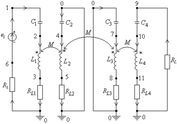
- RL2 = 0.0545 Ω, RL3 = 0.0925 Ω, RL = 30.0 Ω.
- C1 = 0.15784e − 06F, C2 = 0.315685e − 06F, C3 = C1; C4 = C2.
- L1 = 63.76e − 6H, L2 = 32.6e − 06H, L3 = L1, L4 = L2.
- Ri = 1.5 Ω, RL1 = 0.0925 Ω, RL4 = 0.0.0545 Ω, k12 = 0.65.
- V.
- k34 = k12, k23 = 0.035.
- f0 = 50.2 kHz.
- and
- The values of the parameters RL2, RL3, RL and k23 are reduced five times, which leads to the following:
- RL2 = 0.0109 Ω; RL3 = 0.0185 Ω; RL = 6.0 Ω and k23 = 0.007.
- The frequency is equal to f = f0 = 50.2 kHz;
- Coil one to two distance = coil three to four distance: d12 = d34 = 5 cm;
- Coil two to three distance d23 = 30 cm;
- The coils one and three are identical, as well as the coils two and four.
- PRL—the load delivered active power;
- P1—the active power generated by the source ei;
- η21—the load power transmission efficiency;
- The normalized sensitivity of PRL with respect to the parameters RL2, RL3, RL and k23;
- The normalized sensitivity of η21 with respect to the parameters RL2, RL3, RL and k23.
3. Results
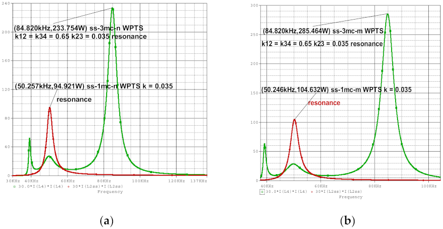
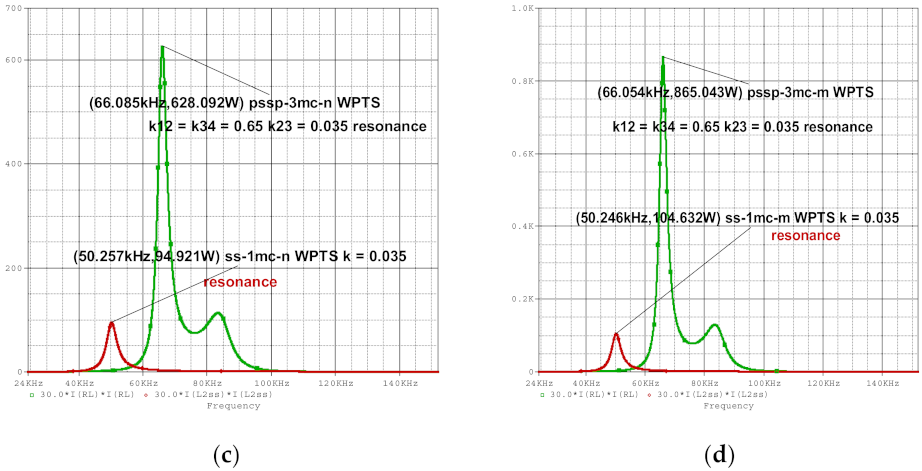
- ss-1mc-n—WPTSs with two coils with series–series connection, one magnetic coupling and nominal values of the parameters.
- ss-3mc-n—WPTSs with the four coils connected in series with three magnetic couplings and nominal values of the parameters.
- pssp-3mc-n—WPTSs having the emitter coil in parallel and the receiver coil in parallel, and the intermediate circuits three and four, each connected in series and with nominal values of the parameters.
- Figure 4b—ss-3mc and ss-1mc connections and the values for resistances RL2 and RL3, (i.e., connection ss-3mc), and the values for resistances RL1 and RL2 (i.e., connection ss-1mc), reduced five times;
- Figure 4d—pssp-3mc and ss-1mc connections and the values for resistances RL2 and RL3, (i.e., for connection pssp-3mc), and values for resistances RL1 and RL2 (i.e., for connection ss-1mc), reduced five times.
4. Comments
- The maximum values of PRL and of η21 correspond to the connection pssp-3mc-m and 3mc-ss-m, respectively, but at the following different frequencies: kHz and kHz.
- It is obvious that the maximum values of PRL and of η21 obtained for any connection type of WPTS occurred for the cases of reduced resistance values, given the diminished the Joule–Lenz losses.
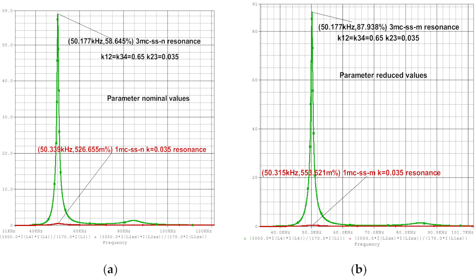
- Figure 5a–d represent the dependency on the frequency of the power transfer efficiency as follows:
- Figure 5b—ss-3mc and ss-1mc connections and the values for resistances RL2 and RL3, (i.e., connection ss-3mc), and the values for resistances RL1 and RL2 (i.e., connection ss-1mc), reduced five times.
- Figure 5d—pssp-3mc and ss-1mc connections and the values for resistances RL2 and RL3, (i.e., for connection pssp-3mc), and values for resistances RL1 and RL2 (i.e., for connection ss-1mc), reduced five times.
- After assessing the graphical representation from Figure 5a–d, it results that:
- The frequencies values corresponding to maxim efficiency for connection ss-1mc-n, ss-3mc-n, ss-1mc-m and ss-3mc-m (Figure 5a,b) are the same, approximately, 50.25 kHz, close to the resonance frequency f0 = 50.2 kHz.
- The frequency values corresponding to the maxim efficiency for connections pssp-3mc-n and pssp-3mc-m (Figure 5c,d) are very close: and
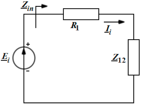
- The first step in the calculation of the resonance frequency for each type of WPTS is the computation of the input impedance of the equivalent circuit. Then, the resonance frequency results from the condition . Table 2 contains the values of PRL and η21 for each resonance frequency.
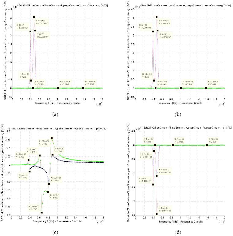
- Figure 6a— for connections ss-3mc-n, pssp-3mc-n and ss-1mc-n;
- Figure 6b— for connections ss-3mc-m, pssp-3mc-m and ss-1mc-m, whereas the values of the resistances RL2 and RL3, for connections ss-3mc and pssp-3mc-m, and the values of the resistances RL1 and RL2 for connection ss-1mc, are five times reduced;
- Figure 6c— for connections ss-3mc-n, pssp-3mc-n and ss-1mc-n;
- Figure 6d— for connections ss-3mc-m, pssp-3mc-m and ss-1mc-m, whereas the values of the resistances RL2 and RL3, for connections ss-3mc and pssp-3mc-m, and the values of the resistances RL1 and RL2 for connection ss-1mc, are five times reduced.
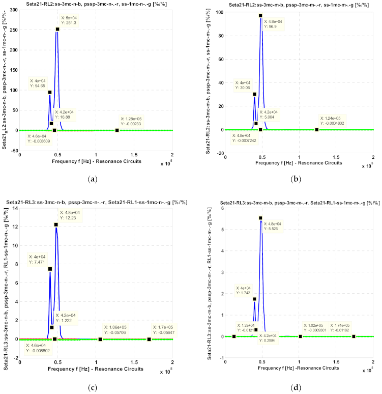
- Figure 7a— for connections ss-3mc-n, pssp-3mc-n and ss-1mc-n;
- Figure 7b— for connections ss-3mc-m, pssp-3mc-m and ss-1mc-m, whereas the values of the resistances RL2 and RL3, for connections ss-3mc and pssp-3mc-m, and the values of the resistances RL1 and RL2 for connection ss-1mc, are five times reduced;
- Figure 7c— for connections ss-3mc-n, pssp-3mc-n and ss-1mc-n;
- Figure 7d— for connections ss-3mc-m, pssp-3mc-m and ss-1mc-m, whereas the values of the resistances RL2 and RL3, for connections ss-3mc and pssp-3mc-m, and the values of the resistances RL1 and RL2 for connection ss-1mc, are five times reduced.
- The values of the normalized sensitivities and are relatively small (less than 0.225) around the resonance frequency 50.0 kHz, an observation for which is valid for the connections ss-3mc-n, pssp-3cm-n and ss-1mc-n, respectively, for the connections ss-3mc-m, pssp-3cm-m and ss-1mc-m (see Figure 6a–c);
- The largest value of is equal to 251.0 recorded at 50.0 kHz, for the connection ss-3mc-n (see Figure 7a), and is equal to 96.9 at 48.0 kHz for connection ss-3mc-m (see Figure 6b). The absolute values of the sensitivities corresponding to the other connections are very small, less than 0.0036 (see Figure 7a,b);
- The absolute values of the sensitivities for connections ss-3mc-n and ss-3mc-m have maximum values equal to 12.23 at 48.0 kHz (see Figure 7c), and equal to 5.526 at the same frequency of 48.0 kHz respectively. For the other connections, the normalized sensitivities have been very small values: 0.00093–0.057 (see Figure 7c,d).
5. Conclusions
Author Contributions
Funding
Conflicts of Interest
References
- Iordache, M.; Dumitriu, L.; Niculae, D. Power Transfer by Magnetic Induction Using Coupled-Mode Theory. In Wireless Power Transfer, 2nd ed.; Book Chapter in the Book; Agbinya, J.I., Ed.; River Publishers Series in Communications: Aalborg, Denmark, 2016; pp. 1–69, Chapter 1; ISBN 9788793237629. [Google Scholar]
- de Miranda, C.M.; Pichorim, S.F.; Abatti, P.J. On the impact of relay circuit losses in four-coil wireless power transfer systems, systems. Int. J. Circuit Theory Appl. 2019, 47, 1922–1932. Available online: https://onlinelibrary.wiley.com/doi/full/10.1002/cta.2685 (accessed on 17 March 2020).
- Yi, Y.; Buttner, U.; Fan, Y.; Foulds, I.G. Design and optimization of a 3-coil resonance-based wireless power transfer system for biomedical implants. Int. J. Circ. Theor. Appl. 2015, 43, 1379–1390. [Google Scholar] [CrossRef]
- Liu, Z.; Su, Y.; Zhao, Y.; Hu, A.P.; Dai, X. Capacitive Power Transfer System with Double T-type Resonant Network for Mobile Devices Charging/Supply. IEEE Trans. Power Electron. 2021. [Google Scholar] [CrossRef]
- Zhou, Z.; Liu, Z.; Su, H. Multi-Objective Optimization of the Wireless Power Transfer System for Electric Vehicles. In Proceedings of the 2020 IEEE Wireless Power Transfer Conference (WPTC), Seoul, Korea, 15–19 November 2020; pp. 215–218. [Google Scholar] [CrossRef]
- Shin, J. Design and implementation of shaped magnetic resonance based wireless power transfer system for roadway-powered moving electric vehicles. IEEE Trans. Ind. Electron. 2014, 61, 1179–1192. [Google Scholar] [CrossRef]
- Seshadri, S.; Kavitha, M.; Bobba, P.B. Effect of coil structures on performance of a four-coil WPT powered medical implantable devices. In Proceedings of the International Conference on Power, Instrumentation, Control and Computing (PICC), Thrissur, India, 18–20 January 2018; pp. 1–6. [Google Scholar]
- Imura, T.; Okabe, H.; Hori, Y. Basic Experimental Study on Helical Antennas of Wireless Power Transfer for Electric Vehicles by using Magnetic Resonant Couplings. In Proceedings of the Vehicle Power and Propulsion Conference, Dearborn, MI, USA, 7–10 September 2009; IEEE Xplore: Piscataway, NJ, USA; pp. 936–940, ISBN 978-1-4244-2601-4/010/2010. [Google Scholar]
- ANSOFT Q3D EXTRACTOR, User Guide. Available online: www.ANSOFT.com (accessed on 10 September 2019).
- Chen, W.; Lu, W.; Wang, X. Circuit modeling and efficiency analysis for wireless power transfer system with shielding. Int. J. Circ. Theor. Appl. 2019, 47, 294–303. [Google Scholar] [CrossRef]
- Hassen, T.S.; Elzawary, A.M.; Alaskary, S. A Proposed Trend toward Capacitive Coupling for Wireless Power Transfer Technology. In Proceedings of the 2021 International Telecommunications Conference (ITC-Egypt), Alexandria, Egypt, 13–15 July 2021; pp. 1–9. [Google Scholar] [CrossRef]
- Cheng, M.; Luo, Y.; Yang, Y.; Zhang, Y.; Xu, Y. Performance Optimization Method of Wireless Power Transfer System Based on Magnetic Field Editing. In Proceedings of the 2021 4th International Conference on Advanced Electronic Materials, Computers and Software Engineering (AEMCSE), Changsha, China, 26–28 March 2021; pp. 10–17. [Google Scholar] [CrossRef]
- Jo, H.; Kim, J.; Seo, S.; Bien, F. A Wireless Power Transfer System with Uniformly High Transfer Efficiency for Free Arrangement of the Receiver in a Wide Area. In Proceedings of the 2020 IEEE PELS Workshop on Emerging Technologies: Wireless Power Transfer (WoW), Seoul, Korea, 15–19 November 2020; pp. 312–315. [Google Scholar] [CrossRef]
- Iordache, L.; Iordache, M. Optimization of Magnetic Coupled Resonator Structure Used in Wireless Electromagnetic Energy Transfer. UPB Sci. Bull. Ser. C-Electr. Eng. 2016, 78, 137–148. [Google Scholar]
- Kurs, A.; Karalis, A.; Moffatt, R.; Joannopoulos, J.D.; Fisher, P.; Soljačić, M. Wireless Power Transfer via Strongly Coupled Magnetic Resonances. Sci. Exp. 2007, 317, 83–86. [Google Scholar] [CrossRef] [PubMed] [Green Version]
- Moon, S.; Moon, G. Wireless Power Transfer System with an Asymmetric Four-Coil Resonator for Electric Vehicle Battery Chargers. IEEE Trans. Power Electron. 2016, 31, 6844–6854. [Google Scholar]
- Wang, X.; Wang, Y.; Fan, G.; Hu, Y.; Nie, X.; Yan, Z. Experimental and Numerical Study of a Magnetic Resonance Wireless Power Transfer System Using Superconductor and Ferromagnetic Metamaterials. IEEE Trans. Appl. Supercond. 2018, 28, 1–6. [Google Scholar] [CrossRef]
- Basar, M.R.; Ahmad, M.Y.; Cho, J.; Ibrahim, F. An Improved Wearable Resonant Wireless Power Transfer System for Biomedical Capsule Endoscope. IEEE Trans. Ind. Electron. 2018, 65, 7772–7781. [Google Scholar] [CrossRef]
- Chan, C.A.; Hao, P.; Gygax, A.F.; Nirmalathas, A. Wireless Charging of Smartwear for Health and Safety Monitoring System. In Proceedings of the 2020 IEEE PELS Workshop on Emerging Technologies: Wireless Power Transfer (WoW), Seoul, Korea, 15–19 November 2020; pp. 223–227. [Google Scholar] [CrossRef]
- Lee, J.; Kim, M.-Y.; Lee, S.-H. A New Multilevel Inductive Power Transfer System. In Proceedings of the 2020 IEEE PELS Workshop on Emerging Technologies: Wireless Power Transfer (WoW), Seoul, Korea, 15–19 November 2020; pp. 264–270. [Google Scholar] [CrossRef]
- Hu, Z.; Goodall, M.; Zhao, L.; Zhu, Q.; Hu, A.P. A Comparative Study of Different Compensation Topologies for Capacitive Power Transfer. In Proceedings of the 2020 IEEE PELS Workshop on Emerging Technologies: Wireless Power Transfer (WoW), Seoul, Korea, 15–19 November 2020; pp. 389–394. [Google Scholar] [CrossRef]
- Weerasekara, H.; Hata, K.; Imura, T.; Fujimoto, H.; Hori, Y. Efficiency Maximization in Wireless Power Transfer Systems for Resonance Frequency Mismatch. In Proceedings of the 2019 IEEE PELS Workshop on Emerging Technologies: Wireless Power Transfer (WoW), London, UK, 18–21 June 2019; pp. 363–366. [Google Scholar] [CrossRef]
- Reatti, A.; Pugi, L.; Corti, F.; Grasso, F. Effect of Misalignment in a Four Plates Capacitive Wireless Power Transfer System. In Proceedings of the 2020 IEEE International Conference on Environment and Electrical Engineering and 2020 IEEE Industrial and Commercial Power Systems Europe (EEEIC/I&CPS Europe), Madrid, Spain, 9–12 June 2020; pp. 1–4. [Google Scholar] [CrossRef]
- Iordache, M. Chestiuni Speciale de Electrotehnca (Special Works of Electrotehnics); MATRIX ROM: Bucharest, Romania, 2016; ISBN 978-606-25-0283-6. [Google Scholar]
- Niculae, D.; Dumitriu, L.; Iordache, M.; Ilie, A.; Mandache, L. Magnetic Resonant Couplings Used in Wireless Power Transfer to Charge the Electric Vehicle Batteries; AGIR: Bucharest, Romania, 2011. [Google Scholar]
- Agbinya, J.I. Principles of Inductive Near Field Communications for Internet of Things; River Publishers: Gistrup, Denmark, 2011; ISBN 978-87-92329-52-3. [Google Scholar]
- Hamam, R.E.; Karalis, A.; Joannopoulos, J.D.; Soljacic, M. Coupled-Mode Theory for General Free-Space Resonant Scattering of Waves. Phys. Rev. A 2007, 75, 053801. [Google Scholar] [CrossRef] [Green Version]



| Connection Type | the Coordinates of the Maximum of PRL | the Coordinates of the Maximum of the η21 |
|---|---|---|
| 1mc-ss-n | (50.257 kHz, 94.921 W) | (50.339 kHz, 0.5266%) |
| 1mc-ss-m | (50.246 kHz, 104.632 W) | (50.315 kHz, 0.55362%) |
| 3mc-ss-n | (84.82 kHz, 233.754 W) | (50.177 kHz, 58.645%) |
| 3mc-ss-m | (84.82 kHz, 259.5464 W) | (50.17 kHz, 87.938%) |
| 3mc-pssp-n | (66.085 kHz, 628.092 W) | (84.957 kHz, 66.607%) |
| 3mc-pssp-m | (66.054 kHz, 855.222 W) | kHz, 84.968%) |
| Connection Type | Resonance Frequency (kHz) | Power PRL (W) | Efficiency η21 (%) |
|---|---|---|---|
| ss-1mc-n | 50.199 | 94.774 | 0.525 |
| ss-1mc-m | 50.2 | 104.484 | 0.552 |
| ss-3mc-n | 39.07 50.2 84.966 | 50.352 26.9157 233.456 | 0.2976 58.659 1.39265 |
| ss-3mc-m | 39.069 50.2 84.967 | 56.305 28.338 259.188 | 0.3147 87.933 1.469 |
| pssp-3mc-n | 38.865.209 65.209 84.589 | 1.116 585.212 101.671 | 11.239 3.8966.895 |
| pssp-3mc-m | 38.856 65.313 84.386 | 0.00921 156.537 0.947 | 0.1864 0.893.962 |
Publisher’s Note: MDPI stays neutral with regard to jurisdictional claims in published maps and institutional affiliations. |
© 2021 by the authors. Licensee MDPI, Basel, Switzerland. This article is an open access article distributed under the terms and conditions of the Creative Commons Attribution (CC BY) license (https://creativecommons.org/licenses/by/4.0/).
Share and Cite
Niculae, D.M.; Stanculescu, M.; Deleanu, S.; Iordache, M.; Bobaru, L. Wireless Power Transfer Systems Optimization Using Multiple Magnetic Couplings. Electronics 2021, 10, 2463. https://doi.org/10.3390/electronics10202463
Niculae DM, Stanculescu M, Deleanu S, Iordache M, Bobaru L. Wireless Power Transfer Systems Optimization Using Multiple Magnetic Couplings. Electronics. 2021; 10(20):2463. https://doi.org/10.3390/electronics10202463
Chicago/Turabian StyleNiculae, Dragoș Marin, Marilena Stanculescu, Sorin Deleanu, Mihai Iordache, and Lavinia Bobaru. 2021. "Wireless Power Transfer Systems Optimization Using Multiple Magnetic Couplings" Electronics 10, no. 20: 2463. https://doi.org/10.3390/electronics10202463
APA StyleNiculae, D. M., Stanculescu, M., Deleanu, S., Iordache, M., & Bobaru, L. (2021). Wireless Power Transfer Systems Optimization Using Multiple Magnetic Couplings. Electronics, 10(20), 2463. https://doi.org/10.3390/electronics10202463


