Article

Wireless Power Transfer Systems Optimization Using Multiple Magnetic Couplings

1
Department of Electrical Engineering, University Politehnica of Bucharest, 060042 Bucharest, Romania
2
School of Applied Sciences and Technology, Northern Alberta Institute of Technology, Edmonton, AB 11762-106, Canada
*
Author to whom correspondence should be addressed.
Electronics 2021, 10(20), 2463; https://doi.org/10.3390/electronics10202463
Submission received: 14 September 2021 / Revised: 4 October 2021 / Accepted: 7 October 2021 / Published: 11 October 2021
(This article belongs to the Special Issue Circuit Analysis and Simulation of Modern Electric Systems)

Abstract

:
Multiple magnetic couplings used to increase the link distance in wireless power transfer systems (WPTSs) are not new. An efficient power transfer in conditions of an extended link distance requires a series connection of the intermediate coils. However, all four connections of the emitter and receiver coils are equally possible. This present paper conducts an extensive analysis of WPTSs utilizing three magnetic couplings. The type of connection of the emitter and receiver coils represented the criterion utilized for the WPTS optimization assessment. The first step requires the determination of the schematic of the sinusoidal equivalent circuit. Then, one synthesizes the functions describing the system performances (e.g., the amount of delivered active power or efficiency) by applying the entirely symbolic and or the hybrid symbolic-numerical formalism. The output of such functions consists of appropriate representation in the frequency domain, based upon Laplace state variable equations (SVE) or complex or Laplace modified nodal equations (MNE). The dependency of the WPTS performance on the number of magnetic couplings and their parameters included a study on resistive loss minimization. The minimization applies to the intermediate coils, whereas the outcomes are the active delivered power and the power transfer efficiency—the first study case aimed at a comparison between two distinct WPTSs: three magnetic couplings versus two. The second case of the study compared the WPTSs having a series connection of three magnetic couplings with those built with the emitter-receiver resonators in parallel. One determined the normalized sensitivities as frequency functions, which depend on circuit resistances, load resistance and the coupling factor between the second and the third coil. The optimization algorithms are suitable for computing optimal parameters of the given circuit to ensure maximum and minimum values of the performance value. Good simulation examples followed the proposed optimization techniques.

1. Introduction

Wireless transfer of electromagnetic energy (WTEE) is a new technology, which can bring electricity to consumers, whereas the system interconnection through cables is either impossible or impractical. The transfer distance requires enough electromagnetic field strength to allow for an efficient power transfer. Suppose both the transmitter and the receiver fulfill the condition of magnetic resonance. In such a case, the resonant bodies perform a much more efficient energy transfer than the non-resonant ones. However, the losses accounted for from the total transferred energy are high, around 30%. Despite this impediment, there are several significant applications of WTEE [1,2,3,4,5,6,7,8,9].
The literature presents several types of WTEEE systems, yet the four-coil system (with three magnetic couplings) shows tremendous interest because it offers remarkable features [1,2,3,4,10,11,12,13,14,15,16,17,18]. This system displays a high degree of implementation freedom regarding the alternative configuration and S parameter values [5,19,20,21,22,23,24].
The WTEE system consists of a connection to the source-circuit one, the relay-circuits for extending the link distance-circuits two and three, and the load circuit four. Minimization of the relay-circuits losses represents the condition for an efficient power transfer [5,13,19,20,21,22,23,24]. Recent papers encourage the utilization of the high-temperature superconductors (HTS) for reducing the ohmic losses in the coils and to increase their quality factor. The implementation of the necessary system raises some problems to cool the HTS coils cryogenically. Therefore, one can design and implement a hybrid system consisting of HTS and copper-conductor coils [5]. There are biomedical applications with direct implantation of the load circuit and relay circuits within the same biological tissue [1,22,24]. Therefore, the dimension of the coils involved in the WPTS becomes a critical parameter. For such applications, it is essential to study the impact that individual relay-circuits have on the performance of the WPTS. The content of the present paper addresses the WPTS utilizing three magnetic couplings. The assessment of the WPTS optimization, the type of connection of the emitter and receiver coils, represented the criterion utilized for the WPTS optimization assessment.
The first step requires the determination of the schematic of the sinusoidal equivalent circuit. Then, one synthesizes the functions describing the system performances (e.g., the amount of delivered active power or efficiency) by applying the entirely symbolic or hybrid symbolic-numerical formalism. The representation for the output of such functions in the frequency domain is appropriate. [1,6,11,12,13,14,15].
To assess the dependency of the WPTS performance on the number of magnetic couplings and the parameter values of the magnetically coupled resonators [6,7,15,16,17], one can investigate the following:
  • The effect of the intermediate circuits (coils) ohmic losses reduction on the values of delivered active power and the power transfer efficiency power.
  • How a WPTS with three magnetic couplings compare with those with two magnetic couplings.
  • The performance of WPTSs with three magnetic couplings connected in series compared to those of WPTSs having emitter–receiver resonators in parallel.
One determined the normalized sensitivities as frequency functions, which depend on circuit resistances, load resistance RL and on the coupling factor k23 between the second and the third coil. The dependency on the frequency of the normalized sensitivities may decide on the critical aspect represented by the parameters RL2, RL3, RL and k23 (see Figure 1 and Figure 2). The mechanisms in place, aiming to maximize both the delivered active power and the transfer efficiency, may include the following:
Increasing the number of magnetic couplings of the resonant circuits.
Adjusting the connections of these circuits and their electrical parameters.
There is a constraint: the same value(s) of the frequency correspond to the maximum power and efficiency.
This paper investigates the consequences of losses on each relay-circuit of typical four-coil WPTSs, whereas special attention is dedicated to analyzing the following two critical parameters: power transfer and efficiency.
The structure of the paper is the following: Section 2 consists of a thorough circuit analysis, concluded with the presentation of expressions regarding the parameters of interest. Section 3 contains comparisons between simulation and theoretical results together with their analyses. Section 4 contains the overall conclusions.

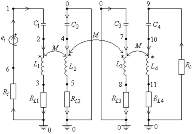
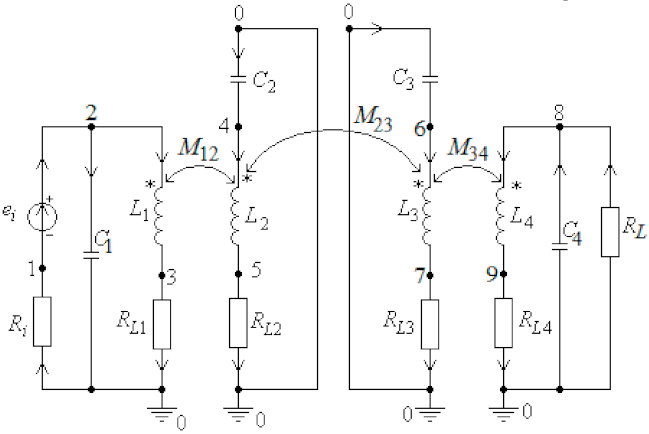
2. Wireless Power Transfer Systems with Multiple Magnetic Couplings

The equivalent circuit of a WPTS with four magnetically coupled coils appears in Figure 1, whereas all four resonators are series-connected, as shown in Figure 2, whereas the first circuit (transmitter circuit) and the fourth circuit (load circuit) are parallel-connected. In the last setup (Figure 2), the second and the third circuits (intermediate circuits) are series-connected.
There are no magnetic couplings other than the adjacent circuits in the configurations from Figure 1 and Figure 2 are subjected to analysis. The transmitter is circuit one (powered by a voltage source), whereas Ri comprises the voltage source’s losses, and resistor RL1 explains the losses encountered by L1 and C1. The relay circuits two and three develop losses in their passive components, modeled by RL2 and RL3.
The load circuit (Figure 2) has the load resistance RL, whereas the resistor RL4 accounts for the losses developed by the passive components L4 and C4. All the analyzed circuits are resonant at the same angular frequency ω 0 , expressed further by ω 0 = 1 L 1 C 1 = 1 L 2 C 2 = 1 L 3 C 3 = 1 L 4 C 4 .
The simulation of the circuits from Figure 1 and Figure 2 appealed to the entirely symbolic, partially symbolic, and numeric form using the following programs: ACAP (Analogue Circuit Analysis Program), CSAP (Circuit Symbolic Analysis Circuit) and SYSEG (i.e., Symbolic State Equation Generation) [1,6,11,12,13,14,15,25,26,27].
These programs work in conjunction with the more well-known software packages MAPLE and SPICE, whereas MATLAB proved the most suitable for the graphical plots.
Equation (1) denotes P1 the active power generated by the voltage source ei, and PRL the active power delivered to the load:
P 1 = Re E _ i I _ i   and   P R L = R L I _ L 2 .
The efficiency of the active power transmission is as follows:
η 21 = 100 P R L P 1
The maximum active power delivered to the load, according to the Thevenin’s Theorem is as follows:
P R L _ T h e f _ m a x = V _ T h e f 2 4 R L _ T h e f
The normalized sensitivities of active power delivered to the load PRL and of the transmission efficiency η21 defined with respect to any parameter x of the circuits represented in Figure 1 and Figure 2 are as follows:
S x P R L = P R L x x P R L   and   S x η R L = η 21 x x η 21
In a similar manner to that in Equation (4), one can compute any normalized sensitivity.
For the equivalent circuit represented in Figure 1, one neglects the cross-coupling effect between non-adjacent resonators. By introducing the notations R1 = Ri + RL1 and R4 = RL4 + RL, the harmonic complex regime equations considering the four coils at resonance are as follows:
R 1 I _ 1 + j ω M 12 I _ 2 = E _ i   j ω 0 M 12 I _ 1 + R L 2 I _ 2 + j ω 0 M 23 I _ 3 = 0 j ω 0 M 23 I _ 2 + R L 3 I _ 3 + j ω 0 M 34 I _ 4 = 0   j ω 0 M 34 I _ 3 + R 4 I _ 4 = 0
By solving system Equation (5), one obtained the following:
I _ 1 = I _ i = E _ i R L 2 M 34 2 + R 4 M 23 2 ω 0 2 + R L 2 R L 3 R 4 M 12 2 M 34 2 ω 0 4 + M 12 2 R L 3 R 4 + M 34 2 R L 2 R 1 + M 23 2 R 1 R 4 ω 0 2 + R L 1 R L 3 R 1 R 4 I _ 2 = j ω 0 M 12 E _ i R L 3 R 4 + ω 0 2 M 34 2 M 12 2 M 34 2 ω 0 4 + M 12 2 R L 3 R 4 + M 34 2 R L 2 R 1 + M 23 2 R 1 R 4 ω 0 2 + R L 1 R L 3 R 1 R 4 I _ 3 = E _ i ω 0 2 M 12 M 23 R 4 M 12 2 M 34 2 ω 0 4 + M 12 2 R L 3 R 4 + M 34 2 R L 2 R 1 + M 23 2 R 1 R 4 ω 0 2 + R L 1 R L 3 R 1 R 4 I _ 4 = I _ L = j ω 0 3 M 12 M 23 M 34 E _ i M 12 2 M 34 2 ω 0 4 + M 12 2 R L 3 R 4 + M 34 2 R L 2 R 1 + M 23 2 R 1 R 4 ω 0 2 + R L 1 R L 3 R 1 R 4
The complex input impedance, seen from the source output (see Figure 1), is equal to Z _ i n = E _ i I _ i , the complex impedance of circuit two reflected in circuit one is equal to Z _ 12 = j ω 0 M 12 I _ 2 I _ i , the complex impedance of circuit three reflected in circuit two is equal to Z _ 23 = j ω 0 M 23 I _ 3 I _ 2 , whereas the complex impedance of circuit four reflected in circuit three, is equal to Z _ 34 = j ω 0 M 34 I _ 4 I _ 3 . The detailed expressions appear in relation to Equation (7a–d) as follows:
Z _ i n = E _ i I _ i = R 1 R L 2 R L 3 R 4 + R 1 R L 2 ω 2 M 34 2 + R L 3 R 4 ω 2 M 12 2 + ω 4 M 12 2 M 34 2 + R 1 R 4 ω 2 M 23 2 R L 2 R L 3 R 4 + R L 2 ω 2 M 34 2 + R 4 ω 2 M 23 2
Z _ 12 = j ω 0 M 12 I _ 2 I _ i = ω 0 M 12 2 R L 3 R 4 + ω 0 2 M 34 2 R L 2 R L 3 R 4 + R L 2 ω 0 2 M 34 2 + R 4 ω 0 2 M 23 2
Z _ 23 = j ω 0 M 23 I _ 3 I _ 2 = ω 0 2 M 12 2 R 4 R L 3 R 4 + ω 0 2 M 34 2
Z _ 34 = j ω 0 M 34 I _ 4 I _ 3 = ω 0 2 M 34 2 R 4
Consequently, the equivalent circuit of the four-coil WPTS, with Z12 being the reflected impedance in circuit one, seen by the voltage source, is given in Figure 3.
Solving the circuit in Figure 3, the current Ii has the expression from Equation (6).
The overall system efficiency requires the computation of the power transferred to circuit four ( P R L = R L I _ L 2 and the power delivered by the source ( P 1 = R e E _ i I _ i = R 1 + Z _ 12 I _ i 2 ), yielding to Equation (8).
η 21 = 100 P R L P 1 = 100 R L R 1 + Z 12 I _ L 2 I _ i 2 .
By introducing the expressions given by Equation (7a–d) into the relation defining efficiency (8), the concluding relationship utilized to express the efficiency became the following:
η 21 = 100 R L R 1 + Z 12 ω 0 3 M 12 2 M 23 2 M 34 2 R L 2 M 34 2 + R 4 M 23 2 ω 2 + R L 2 R L 3 R 4 .
A similar procedure described by Equations (5)–(9) can subject WPTSs configured with parallel-series-series-parallel (p-s-s-p) connections, represented by the equivalent circuit from Figure 2. However, such expressions in the entirely symbolic form are much more complicated.
The two sets of values for the parameters of the equivalent circuits (Figure 1 and Figure 3), considered for simulation, are as follows:
Set 1:
  • RL2 = 0.0545 Ω, RL3 = 0.0925 Ω, RL = 30.0 Ω.
  • C1 = 0.15784e − 06F, C2 = 0.315685e − 06F, C3 = C1; C4 = C2.
  • L1 = 63.76e − 6H, L2 = 32.6e − 06H, L3 = L1, L4 = L2.
  • Ri = 1.5 Ω, RL1 = 0.0925 Ω, RL4 = 0.0.0545 Ω, k12 = 0.65.
  • e i t = 170.0 2 sin ω t V.
  • k34 = k12, k23 = 0.035.
  • f0 = 50.2 kHz.
  • M 12 = k 12 · L 1 · L 2 , M 23 = k 23 · L 2 · L 3 and M 34 = k 34 · L 3 · L 4
Set 2:
  • The values of the parameters RL2, RL3, RL and k23 are reduced five times, which leads to the following:
  • RL2 = 0.0109 Ω; RL3 = 0.0185 Ω; RL = 6.0 Ω and k23 = 0.007.
The parameters are modified as stated above to analyze the variation of the following parameters: how the efficiency and the transmitted power change when the ohmic resistances of the three coils, the load resistance and the coupling factor reduces.
The numerical results for the parameters of the four magnetically coupled coils (Figure 1 and Figure 2) required the application of the software ANSYS EXTRACTOR Q3D [9], in the following conditions:
  • The frequency is equal to f = f0 = 50.2 kHz;
  • Coil one to two distance = coil three to four distance: d12 = d34 = 5 cm;
  • Coil two to three distance d23 = 30 cm;
  • The coils one and three are identical, as well as the coils two and four.
The results of the computations performed using the above-mentioned software programs encompassed the following quantities:
  • PRL—the load delivered active power;
  • P1—the active power generated by the source ei;
  • η21—the load power transmission efficiency;
  • The normalized sensitivity of PRL with respect to the parameters RL2, RL3, RL and k23;
  • The normalized sensitivity of η21 with respect to the parameters RL2, RL3, RL and k23.

3. Results

The results appear in graphical form, in which the computed quantities are functions of the frequency. There are the following two categories of comparisons regarding the results:
One compared all the graphical plots with those of WPTSs with only two resonators (with a single magnetic coupling k23) and with the series–series (ss) connection of the two coils. The magnetic couplings k12 and k34 are strong and k23 is weak. The obtained efficiency is superior to that of two magnetic couplings systems for the considered parameter values.
The following notations are in use:
  • ss-1mc-n—WPTSs with two coils with series–series connection, one magnetic coupling and nominal values of the parameters.
  • ss-3mc-n—WPTSs with the four coils connected in series with three magnetic couplings and nominal values of the parameters.
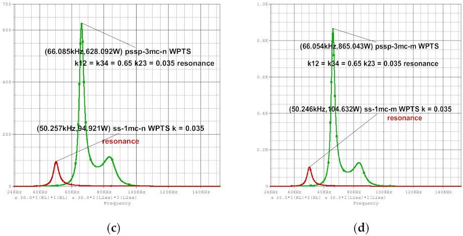
  • pssp-3mc-n—WPTSs having the emitter coil in parallel and the receiver coil in parallel, and the intermediate circuits three and four, each connected in series and with nominal values of the parameters.
In all the simulations, the WPTS fulfilled the resonance condition.
Figure 4a–d represent the dependency on the frequency of the active power delivered to the load PRL as follows:
  • Figure 4a—ss-3mc and ss-1mc connections for nominal values of the parameters;
  • Figure 4b—ss-3mc and ss-1mc connections and the values for resistances RL2 and RL3, (i.e., connection ss-3mc), and the values for resistances RL1 and RL2 (i.e., connection ss-1mc), reduced five times;
  • Figure 4c—pssp-3mc and ss-1mc connections and nominal values of the parameters;
  • Figure 4d—pssp-3mc and ss-1mc connections and the values for resistances RL2 and RL3, (i.e., for connection pssp-3mc), and values for resistances RL1 and RL2 (i.e., for connection ss-1mc), reduced five times.
Table 1 contains the maximum values of the active power transferred to the load, the maximum efficiency and their frequencies for all configurations and connections under scrutiny.
From Figure 4a–d, one can observe that the largest value of the active power delivered to the load is P R L _ p s s p _ 3 m c _ m _ m a x = 855.22 W at a frequency f P R L _ p s s p _ 3 m c _ m _ m a x = 66.054 kHz, whereas the maximum transmission efficiency value is equal to η 21 _ s s _ 3 m c _ m _ m a x = 87.938 % corresponding to the frequency f η 21 _ s s _ 3 m c _ m _ m a x = 50.17   kHz.

4. Comments

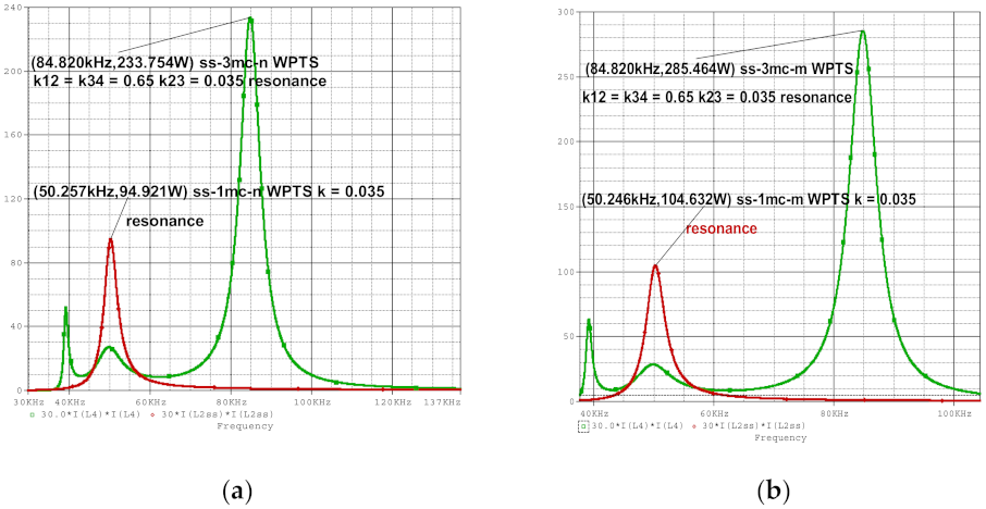
  • The maximum values of PRL and of η21 correspond to the connection pssp-3mc-m and 3mc-ss-m, respectively, but at the following different frequencies: f P R L _ p s s p _ 3 m c _ m _ m a x = 66.054   kHz and f η 21 _ s s _ 3 m c _ m _ m a x = 50.017   kHz.
  • It is obvious that the maximum values of PRL and of η21 obtained for any connection type of WPTS occurred for the cases of reduced resistance values, given the diminished the Joule–Lenz losses.
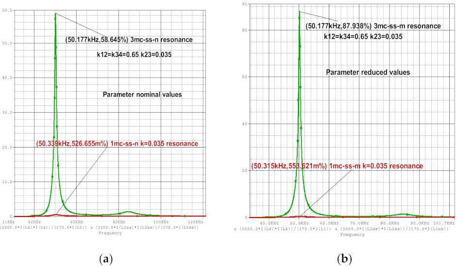
  • Figure 5a–d represent the dependency on the frequency of the power transfer efficiency as follows:
  • Figure 5a—ss-3mc and ss-1mc connections for nominal values of the parameters.
  • Figure 5b—ss-3mc and ss-1mc connections and the values for resistances RL2 and RL3, (i.e., connection ss-3mc), and the values for resistances RL1 and RL2 (i.e., connection ss-1mc), reduced five times.
  • Figure 5c—pssp-3mc and ss-1mc connections and nominal values of the parameters.
  • Figure 5d—pssp-3mc and ss-1mc connections and the values for resistances RL2 and RL3, (i.e., for connection pssp-3mc), and values for resistances RL1 and RL2 (i.e., for connection ss-1mc), reduced five times.
  • After assessing the graphical representation from Figure 5a–d, it results that:
  • The frequencies values corresponding to maxim efficiency for connection ss-1mc-n, ss-3mc-n, ss-1mc-m and ss-3mc-m (Figure 5a,b) are the same, approximately, 50.25 kHz, close to the resonance frequency f0 = 50.2 kHz.
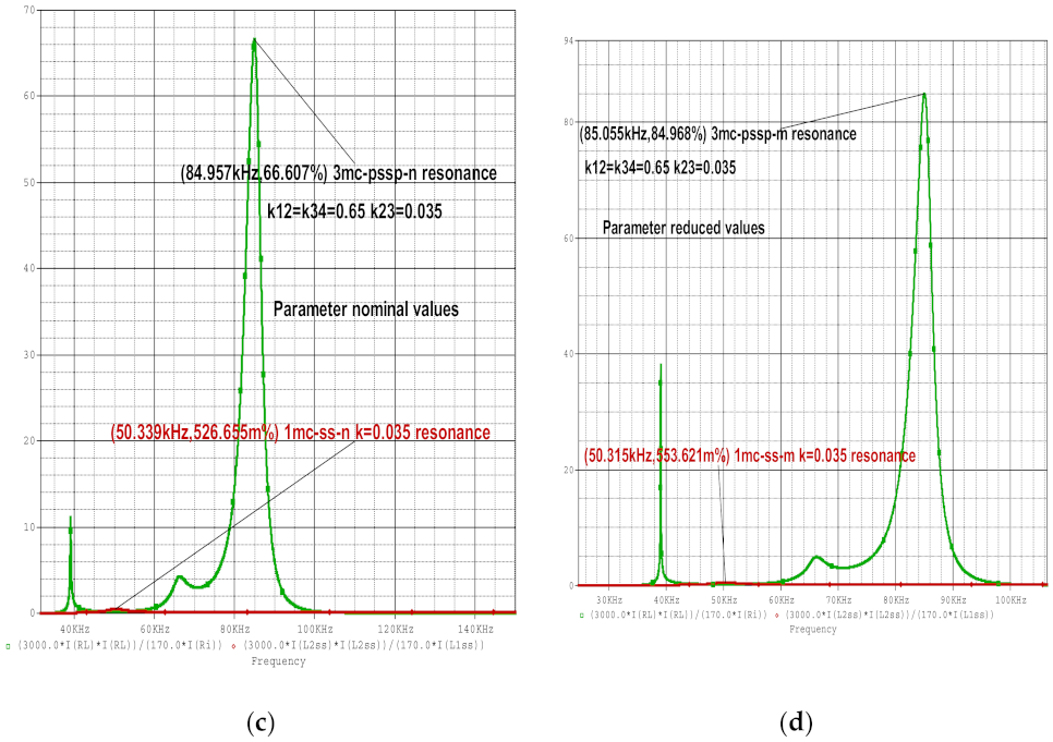
  • The frequency values corresponding to the maxim efficiency for connections pssp-3mc-n and pssp-3mc-m (Figure 5c,d) are very close: f   η 21 _ p s s p _ 3 m c _ n _ m a x = 84.957   kHz and f   kHz η 21 _ p s s p _ 3 m c _ m _ m a x = 85.035   kHz .
  • The splitting frequency occurs for all types of connections and appear in all the previously defined Figure 4 and Figure 5.
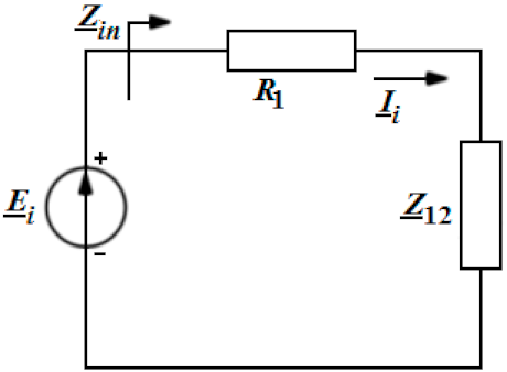
  • The first step in the calculation of the resonance frequency for each type of WPTS is the computation of the input impedance Z _ i n = E _ i I _ i   of the equivalent circuit. Then, the resonance frequency results from the condition   I m Z _ i n = 0 . Table 2 contains the values of PRL and η21 for each resonance frequency.
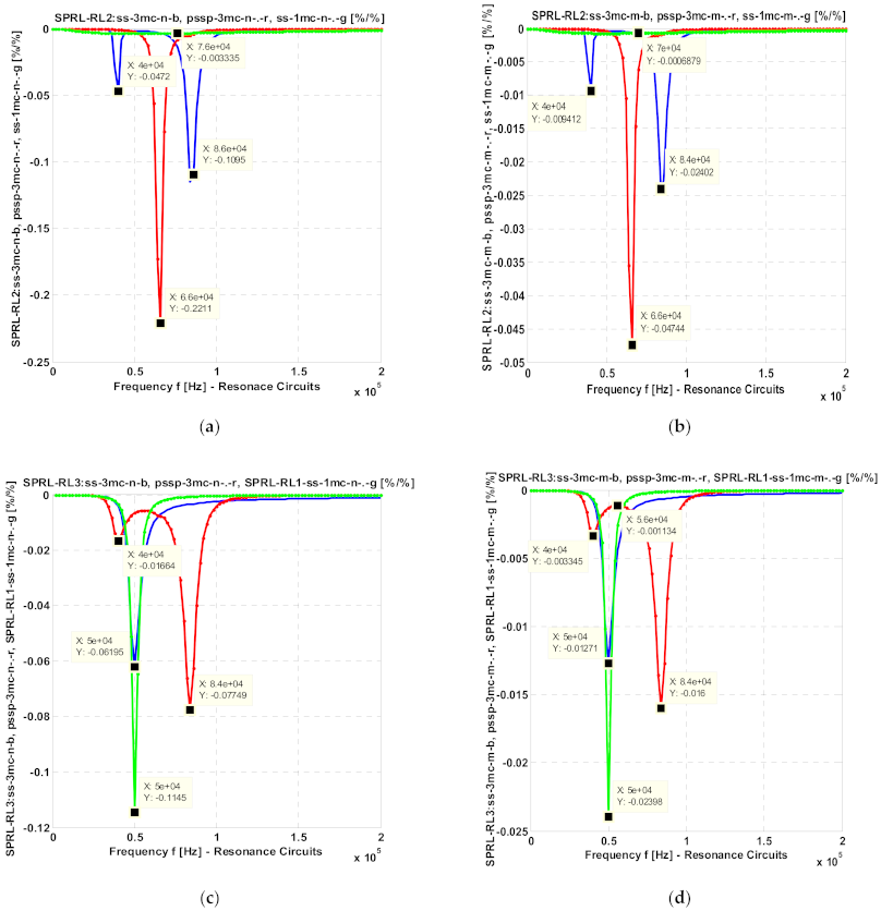
  • According to Table 2, one can observe that the values of PRL and of η21, corresponding to the resonance frequencies for all the WPTSs analyzed, are much smaller than those shown in Figure 4a–d and Figure 5a–d.
Figure 6a–d present the following normalized sensitivity regarding the active power transferred to the load PRL, as a function of coils resistances RL2 and RL3:
  • Figure 6a—   S R L 2 P R L for connections ss-3mc-n, pssp-3mc-n and ss-1mc-n;
  • Figure 6b— S R L 2 P R L for connections ss-3mc-m, pssp-3mc-m and ss-1mc-m, whereas the values of the resistances RL2 and RL3, for connections ss-3mc and pssp-3mc-m, and the values of the resistances RL1 and RL2 for connection ss-1mc, are five times reduced;
  • Figure 6c— S R L 3 P R L for connections ss-3mc-n, pssp-3mc-n and ss-1mc-n;
  • Figure 6d— S R L 3 P R L for connections ss-3mc-m, pssp-3mc-m and ss-1mc-m, whereas the values of the resistances RL2 and RL3, for connections ss-3mc and pssp-3mc-m, and the values of the resistances RL1 and RL2 for connection ss-1mc, are five times reduced.
Figure 7a–d presents the following normalized sensitivity of the active power transmission efficiency η21 as a function of coils resistances RL2 and RL3:
  • Figure 7a— S R L 2 η 21 for connections ss-3mc-n, pssp-3mc-n and ss-1mc-n;
  • Figure 7b— S R L 2 η 21 for connections ss-3mc-m, pssp-3mc-m and ss-1mc-m, whereas the values of the resistances RL2 and RL3, for connections ss-3mc and pssp-3mc-m, and the values of the resistances RL1 and RL2 for connection ss-1mc, are five times reduced;
  • Figure 7c— S R L 3 η 21 for connections ss-3mc-n, pssp-3mc-n and ss-1mc-n;
  • Figure 7d— S R L 3 η 21 for connections ss-3mc-m, pssp-3mc-m and ss-1mc-m, whereas the values of the resistances RL2 and RL3, for connections ss-3mc and pssp-3mc-m, and the values of the resistances RL1 and RL2 for connection ss-1mc, are five times reduced.
  • By evaluating the information presented in Figure 6 and Figure 7, one can draw the following interesting conclusions:
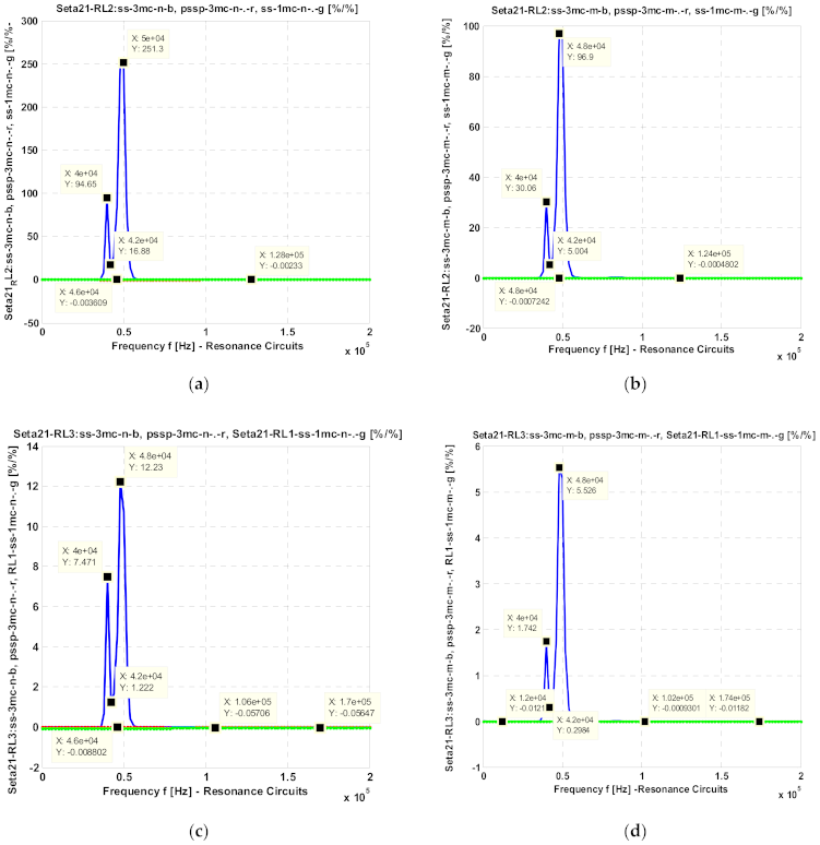
  • The values of the normalized sensitivities S R L 2 P R L and S R L 3 P R L are relatively small (less than 0.225) around the resonance frequency 50.0 kHz, an observation for which is valid for the connections ss-3mc-n, pssp-3cm-n and ss-1mc-n, respectively, for the connections ss-3mc-m, pssp-3cm-m and ss-1mc-m (see Figure 6a–c);
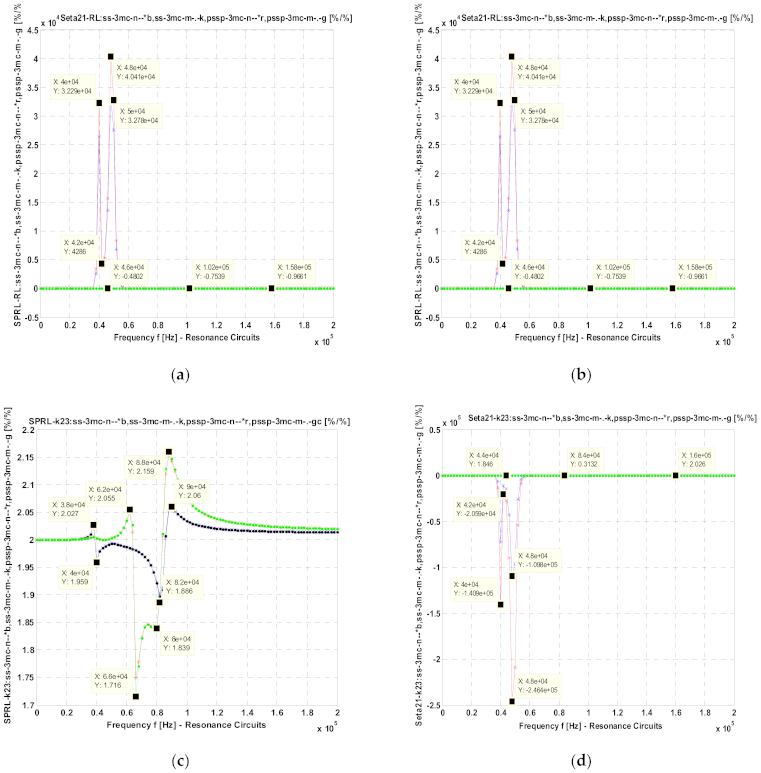
  • The largest value of S R L 2 P R L is equal to 0.2211 at 66.0 kHz, for the connection pssp-3mc-n (see Figure 6a), whereas the smallest value is equal to 0.000688 recorded at 70.0 kHz, for the connection ss-1mc-m (see Figure 6b);
  • The largest value of S R L 3 P R L is equal to 0.1145 at f = 50.0 kHz for the connection ss-1mc-n, in case of RL1 = RL3 (see Figure 6c), whereas the smallest value of this sensitivity is equal to 0.001134 recorded at f = 40.0 kHz (see Figure 6d) for the connection pssp-3mc-m;
  • The absolute values of the sensitivities S R L 2 P R L and S R L 3 P R L are larger for all the connection types, for nominal values of the parameters (see Figure 6a,c) than for the case when the values for the resistances RL2 and RL3 (RL1 for ss-1mc) are five times reduced (see Figure 6b,d);
  • The largest value of S R L 2 η 21 is equal to 251.0 recorded at 50.0 kHz, for the connection ss-3mc-n (see Figure 7a), and is equal to 96.9 at 48.0 kHz for connection ss-3mc-m (see Figure 6b). The absolute values of the sensitivities S R L 2 η 21 corresponding to the other connections are very small, less than 0.0036 (see Figure 7a,b);
  • The absolute values of the sensitivities S R L 3 η 21 for connections ss-3mc-n and ss-3mc-m have maximum values equal to 12.23 at 48.0 kHz (see Figure 7c), and equal to 5.526 at the same frequency of 48.0 kHz respectively. For the other connections, the normalized sensitivities have been very small values: 0.00093–0.057 (see Figure 7c,d).
Figure 8a–d present the normalized sensitivity PRL and the efficiency η21 as functions of load resistance RL and of the coupling coefficient k23, respectively.
  • Figure 8a— S R L P R L for connections ss-3mc-n, ss-3mc-m, pssp-3mc-n and pssp-3mc-m
  • Figure 8b— S R L η 21 for connections ss-3mc-n, ss-3mc-m, pssp-3mc-n and pssp-3mc-m
  • Figure 8c— S k 23 P R L for connections ss-3mc-n, ss-3mc-m, pssp-3mc-n and pssp-3mc-m
  • Figure 8d— S k 23 η 21 for connections ss-3mc-n, ss-3mc-m, pssp-3mc-n and pssp-3mc-m
Figure 8a,c show that the dependencies of sensitivities S R L P R L ( S k 23 P R L ) on frequency are almost identical for all the connection types of WPTSs with magnetic couplings, with a maximum absolute value of 0.9786 recorded at f = 50 kHz for the connections ss-3mc-n and ss-3mc-m. Similarly, the maximum absolute value is equal to 2.159 at f = 88.0 kHz for connections pssp-3mc-n and pssp-3mc-m.
The maximum absolute value of the normalized sensitivity regarding the efficiency as a function of load resistance S R L η 21 has a very large value of 4.041e04 at f = 48.0 kHz recorded for the connection pssp-3mc-n (see Figure 8b), whereas the sensitivity with respect to the coupling value S k 23 η 21 is even larger, with a recorded value of 2.464e05 at f = 48.0 kHz for the connection pssp-3mc-n, (see Figure 8d).
The results from above came following the assumption of very strong magnetic couplings; k12 and k34 are very strong, whereas the magnetic coupling k23 was weak. For some values of the system parameters (given above), we obtained a higher efficiency than the one corresponding to the two magnetic couplings system.

5. Conclusions

The WPTS with three magnetic couplings allows us to extend the distance between the emitter and receiver, leading to more significant values for the maximum load delivered active in conditions of increased power transmission efficiency, compared to WPTSs with a single magnetic coupling. The demand for an optimal structure of a WPTS required the analysis of several configurations of magnetically coupled coils. For each configuration, two sets of electrical parameters completed the simulation scenario. The first step consisted of the assembling of the equivalent scheme of the WPTS operating in conditions of sinusoidal excitation.
The next step involved the representation of the WPTS outcomes, more precisely the power transferred to the load, its efficiency in fully symbolic, and it is in symbolic-numeric form. In such a way, the final form of the WPTS appears expressed as a function of frequency.
The WPTS classified as ss-3mc-m, with the four coils connected in series with three magnetic couplings, provided the highest values of power transferred to the load: P R L _ p s s p _ 3 m c _ m _ m a x = 865.043   W, f P R L _ p s s p _ 3 m c _ m _ m a x = 86.054 kHz); for the efficiency: η 21 _ p s s p _ 3 m c _ m _ m a x = 91.023 %, f η 21 _ p s s p _ 3 m c _ m _ m a x = 85.094 kHz); As a remark the maximum values are obtained at different frequencies.
The reduction in the resistance values (i.e., decreasing the loss due to the Joule–Lenz effect) determines an increase in the load transferred power and of the efficiency, regardless of the connection type. Once confronted with the decision to maximize the efficiency or the load output power, the WPTS designer must compromise. Maximum efficiency demands a loss reduction on circuit two, whereas the maximum load transferred power means to minimize the loss on circuit three. For both of the types of WPTS circuits analyzed, the maximum efficiency occurs in the close neighborhood of the resonance frequency. Moreover, the frequency splitting phenomena represents a constant for all power–frequency and efficiency–frequency characteristics.
The absolute values of the normalized sensitivities calculated versus the load resistance and the coupling coefficient show small values in around the resonance frequency, no matter the type of circuit chosen for the WPTS. This remark is valid regarding the load transferred active power and efficiency. However, the absolute values of the sensitivities are higher in the condition of nominal resistances than for load resistances reduced five times. The load resistance value RL and the magnetic coupling coefficient of the circuits two and three k23 are critical for the process of wireless power transfer process performances. Such affirmation results from the way, the normalized sensitivities associated with the efficiency depend on RL and k23.
The working frequency is the resonance frequency ω 0 , neglecting the impedances corresponding to the coils and the capacitors placed in the series connection.
The computation of the power transferred to the load, PL, and of the efficiency,   η L , performed entirely symbolic, in a system containing magnetically connected coils, leads to optimizing these parameters. Then, the function of each parameter determines the maximum values for the performance parameters. Usually, the optimum is the computed function of the coupling coefficient, load resistance and frequency. Then, one extracted the parameters that ensure the optimum values for the performance.
As future developments, there is a consideration for designing WPTSs with multiple magnetic coupling with maximum power and efficiency at the same frequency.

Author Contributions

Conceptualization, M.S. and M.I.; methodology, M.I., S.D. and M.S.; software, M.I. and D.M.N.; validation, M.S., M.I., S.D. and L.B.; formal analysis, D.M.N. and L.B.; investigation, M.S. and S.D.; resources, M.I., D.M.N. and L.B.; data curation, M.S. and S.D.; writing—original draft preparation, M.I.; writing—review and editing, M.S. and S.D.; visualization, M.S.; supervision, M.I., M.S. and S.D.; project administration, M.I.; funding acquisition, M.S. and S.D. All authors have read and agreed to the published version of the manuscript.

Funding

This research received no external funding.

Conflicts of Interest

The authors declare no conflict of interest.

References

  1. Iordache, M.; Dumitriu, L.; Niculae, D. Power Transfer by Magnetic Induction Using Coupled-Mode Theory. In Wireless Power Transfer, 2nd ed.; Book Chapter in the Book; Agbinya, J.I., Ed.; River Publishers Series in Communications: Aalborg, Denmark, 2016; pp. 1–69, Chapter 1; ISBN 9788793237629. [Google Scholar]
  2. de Miranda, C.M.; Pichorim, S.F.; Abatti, P.J. On the impact of relay circuit losses in four-coil wireless power transfer systems, systems. Int. J. Circuit Theory Appl. 2019, 47, 1922–1932. Available online: https://onlinelibrary.wiley.com/doi/full/10.1002/cta.2685 (accessed on 17 March 2020).
  3. Yi, Y.; Buttner, U.; Fan, Y.; Foulds, I.G. Design and optimization of a 3-coil resonance-based wireless power transfer system for biomedical implants. Int. J. Circ. Theor. Appl. 2015, 43, 1379–1390. [Google Scholar] [CrossRef]
  4. Liu, Z.; Su, Y.; Zhao, Y.; Hu, A.P.; Dai, X. Capacitive Power Transfer System with Double T-type Resonant Network for Mobile Devices Charging/Supply. IEEE Trans. Power Electron. 2021. [Google Scholar] [CrossRef]
  5. Zhou, Z.; Liu, Z.; Su, H. Multi-Objective Optimization of the Wireless Power Transfer System for Electric Vehicles. In Proceedings of the 2020 IEEE Wireless Power Transfer Conference (WPTC), Seoul, Korea, 15–19 November 2020; pp. 215–218. [Google Scholar] [CrossRef]
  6. Shin, J. Design and implementation of shaped magnetic resonance based wireless power transfer system for roadway-powered moving electric vehicles. IEEE Trans. Ind. Electron. 2014, 61, 1179–1192. [Google Scholar] [CrossRef]
  7. Seshadri, S.; Kavitha, M.; Bobba, P.B. Effect of coil structures on performance of a four-coil WPT powered medical implantable devices. In Proceedings of the International Conference on Power, Instrumentation, Control and Computing (PICC), Thrissur, India, 18–20 January 2018; pp. 1–6. [Google Scholar]
  8. Imura, T.; Okabe, H.; Hori, Y. Basic Experimental Study on Helical Antennas of Wireless Power Transfer for Electric Vehicles by using Magnetic Resonant Couplings. In Proceedings of the Vehicle Power and Propulsion Conference, Dearborn, MI, USA, 7–10 September 2009; IEEE Xplore: Piscataway, NJ, USA; pp. 936–940, ISBN 978-1-4244-2601-4/010/2010. [Google Scholar]
  9. ANSOFT Q3D EXTRACTOR, User Guide. Available online: www.ANSOFT.com (accessed on 10 September 2019).
  10. Chen, W.; Lu, W.; Wang, X. Circuit modeling and efficiency analysis for wireless power transfer system with shielding. Int. J. Circ. Theor. Appl. 2019, 47, 294–303. [Google Scholar] [CrossRef]
  11. Hassen, T.S.; Elzawary, A.M.; Alaskary, S. A Proposed Trend toward Capacitive Coupling for Wireless Power Transfer Technology. In Proceedings of the 2021 International Telecommunications Conference (ITC-Egypt), Alexandria, Egypt, 13–15 July 2021; pp. 1–9. [Google Scholar] [CrossRef]
  12. Cheng, M.; Luo, Y.; Yang, Y.; Zhang, Y.; Xu, Y. Performance Optimization Method of Wireless Power Transfer System Based on Magnetic Field Editing. In Proceedings of the 2021 4th International Conference on Advanced Electronic Materials, Computers and Software Engineering (AEMCSE), Changsha, China, 26–28 March 2021; pp. 10–17. [Google Scholar] [CrossRef]
  13. Jo, H.; Kim, J.; Seo, S.; Bien, F. A Wireless Power Transfer System with Uniformly High Transfer Efficiency for Free Arrangement of the Receiver in a Wide Area. In Proceedings of the 2020 IEEE PELS Workshop on Emerging Technologies: Wireless Power Transfer (WoW), Seoul, Korea, 15–19 November 2020; pp. 312–315. [Google Scholar] [CrossRef]
  14. Iordache, L.; Iordache, M. Optimization of Magnetic Coupled Resonator Structure Used in Wireless Electromagnetic Energy Transfer. UPB Sci. Bull. Ser. C-Electr. Eng. 2016, 78, 137–148. [Google Scholar]
  15. Kurs, A.; Karalis, A.; Moffatt, R.; Joannopoulos, J.D.; Fisher, P.; Soljačić, M. Wireless Power Transfer via Strongly Coupled Magnetic Resonances. Sci. Exp. 2007, 317, 83–86. [Google Scholar] [CrossRef] [PubMed] [Green Version]
  16. Moon, S.; Moon, G. Wireless Power Transfer System with an Asymmetric Four-Coil Resonator for Electric Vehicle Battery Chargers. IEEE Trans. Power Electron. 2016, 31, 6844–6854. [Google Scholar]
  17. Wang, X.; Wang, Y.; Fan, G.; Hu, Y.; Nie, X.; Yan, Z. Experimental and Numerical Study of a Magnetic Resonance Wireless Power Transfer System Using Superconductor and Ferromagnetic Metamaterials. IEEE Trans. Appl. Supercond. 2018, 28, 1–6. [Google Scholar] [CrossRef]
  18. Basar, M.R.; Ahmad, M.Y.; Cho, J.; Ibrahim, F. An Improved Wearable Resonant Wireless Power Transfer System for Biomedical Capsule Endoscope. IEEE Trans. Ind. Electron. 2018, 65, 7772–7781. [Google Scholar] [CrossRef]
  19. Chan, C.A.; Hao, P.; Gygax, A.F.; Nirmalathas, A. Wireless Charging of Smartwear for Health and Safety Monitoring System. In Proceedings of the 2020 IEEE PELS Workshop on Emerging Technologies: Wireless Power Transfer (WoW), Seoul, Korea, 15–19 November 2020; pp. 223–227. [Google Scholar] [CrossRef]
  20. Lee, J.; Kim, M.-Y.; Lee, S.-H. A New Multilevel Inductive Power Transfer System. In Proceedings of the 2020 IEEE PELS Workshop on Emerging Technologies: Wireless Power Transfer (WoW), Seoul, Korea, 15–19 November 2020; pp. 264–270. [Google Scholar] [CrossRef]
  21. Hu, Z.; Goodall, M.; Zhao, L.; Zhu, Q.; Hu, A.P. A Comparative Study of Different Compensation Topologies for Capacitive Power Transfer. In Proceedings of the 2020 IEEE PELS Workshop on Emerging Technologies: Wireless Power Transfer (WoW), Seoul, Korea, 15–19 November 2020; pp. 389–394. [Google Scholar] [CrossRef]
  22. Weerasekara, H.; Hata, K.; Imura, T.; Fujimoto, H.; Hori, Y. Efficiency Maximization in Wireless Power Transfer Systems for Resonance Frequency Mismatch. In Proceedings of the 2019 IEEE PELS Workshop on Emerging Technologies: Wireless Power Transfer (WoW), London, UK, 18–21 June 2019; pp. 363–366. [Google Scholar] [CrossRef]
  23. Reatti, A.; Pugi, L.; Corti, F.; Grasso, F. Effect of Misalignment in a Four Plates Capacitive Wireless Power Transfer System. In Proceedings of the 2020 IEEE International Conference on Environment and Electrical Engineering and 2020 IEEE Industrial and Commercial Power Systems Europe (EEEIC/I&CPS Europe), Madrid, Spain, 9–12 June 2020; pp. 1–4. [Google Scholar] [CrossRef]
  24. Iordache, M. Chestiuni Speciale de Electrotehnca (Special Works of Electrotehnics); MATRIX ROM: Bucharest, Romania, 2016; ISBN 978-606-25-0283-6. [Google Scholar]
  25. Niculae, D.; Dumitriu, L.; Iordache, M.; Ilie, A.; Mandache, L. Magnetic Resonant Couplings Used in Wireless Power Transfer to Charge the Electric Vehicle Batteries; AGIR: Bucharest, Romania, 2011. [Google Scholar]
  26. Agbinya, J.I. Principles of Inductive Near Field Communications for Internet of Things; River Publishers: Gistrup, Denmark, 2011; ISBN 978-87-92329-52-3. [Google Scholar]
  27. Hamam, R.E.; Karalis, A.; Joannopoulos, J.D.; Soljacic, M. Coupled-Mode Theory for General Free-Space Resonant Scattering of Waves. Phys. Rev. A 2007, 75, 053801. [Google Scholar] [CrossRef] [Green Version]
Figure 1. The equivalent circuit of a WPTS with four magnetically coupled coils—series.
Electronics 10 02463 g001
Figure 2. A 4-coil WPTS, with circuits 2 and 3 series.
Electronics 10 02463 g002
Figure 3. Equivalent circuit.
Electronics 10 02463 g003
Figure 4. The dependencies on the frequency of the active power delivered to the load PRL for (a) Connections ss-3mc-n and ss-1mc-n; (b) Connections ss-3mc-m and ss-1mc-m, whereas the values of the resistances RL2 and RL3 for connection ss-3mc and the values of the resistances RL1 and RL2 for connection ss-1mc, are reduced five times; (c) Connections pssp-3mc-n and ss-1mc-n; (d) Connections pssp-3mc-m and ss-1mc-m, when the values of the resistances RL2 and RL3 for connection pssp-3mc and the values of the resistances RL1 and RL2 for connection ss-1mc, are reduced five times.
Electronics 10 02463 g004aElectronics 10 02463 g004b
Figure 5. The dependence on the frequency η21 from the source to the load for (a) Connections ss-3mc-n and ss-1mc-n; (b) Connections ss-3mc-m and ss-1mc-m, whereas the values of the resistances RL2 and RL3 for connection ss-3mc and the values of the resistances RL1 and RL2 for connection ss-1mc, are reduced five times; (c) Connections pssp-3mc-n and ss-1mc-n; (d) Connections pssp-3mc-m and ss-1mc-m, when the values of the resistances RL2 and RL3 for connection pssp-3mc and the values of the resistances RL1 and RL2 for connection ss-1mc, are reduced five times.
Electronics 10 02463 g005aElectronics 10 02463 g005b
Figure 6. The dependences on frequency of the normalized sensitivity of the active power in relation with the resistances RL2 and RL3 of the circuits (coils) 2 and 3: (a) S R L 2 P R L for connections ss-3mc-n, pssp-3mc-n and ss-1mc-n; (b) S R L 2 P R L for connections ss-3mc-m, pssp-3mc-m and ss-1mc-m, when the values of the resistances RL2 and RL3, for connections ss-3mc and pssp-3mc-m, and the values of the resistances RL1 and RL2 for connection ss-1mc, respectively, are five times reduced; (c) S R L 3 P R L for connections ss-3mc-n, pssp-3mc-n and ss-1mc-n; (d) S R L 3 P R L for connections ss-3mc-m, pssp-3mc-m and ss-1mc-m when the values of the resistances RL2 and RL3, for connections ss-3mc and pssp-3mc-m, and for the values of the resistances RL1 and RL2 for connection ss-1mc, respectively, are five times reduced.
Electronics 10 02463 g006
Figure 7. The dependences on frequency of the normalized sensitivity of the active power transmission efficiency in relation with the resistances RL2 and RL3 of circuits (coils) 2 and 3: (a) S R L 2 η 21 for connections ss-3mc-n, pssp-3mc-n and ss-1mc-n; (b) S R L 2 η 21 for connections ss-3mc-m, pssp-3mc-m and ss-1mc-m, when the values of the resistances RL2 and RL3, for connections ss-3mc and pssp-3mc-m, and the values of the resistances RL1 and RL2 for connection ss-1mc, respectively, are five times reduced; (c) S R L 3 η 21 for connections ss-3mc-n, pssp-3mc-n and ss-1mc-n; (d) S R L 3 η 21 for connections ss-3mc-m, pssp-3mc-m and ss-1mc-m when the values of the resistances RL2 and RL3, for connections ss-3mc and pssp-3mc-m, and for the values of the resistances RL1 and RL2 for connection ss-1mc, respectively, are five times reduced.
Electronics 10 02463 g007
Figure 8. The dependences on frequency of the normalized sensitivity. (a) S R L P R L for connections ss-3mc-n, ss-3mc-m, pssp-3mc-n and pssp-3mc-m; (b) S R L η 21 for connection ss-3mc-n, ss-3mc-m, pssp-3mc-n and pssp-3mc-m; (c) S k 23 P R L for connections ss-3mc-n, ss-3mc-m, pssp-3mc-n and pssp-3mc-m; (d) S k 23 η 21 for connections ss-3mc-n, ss-3mc-m, pssp-3mc-n and pssp-3mc-m.
Electronics 10 02463 g008
Table 1. Maximum values of the load transferred power and maximum efficiency
Connection Typethe Coordinates of the Maximum of PRLthe Coordinates of the Maximum of the η21
1mc-ss-n(50.257 kHz, 94.921 W)(50.339 kHz, 0.5266%)
1mc-ss-m(50.246 kHz, 104.632 W)(50.315 kHz, 0.55362%)
3mc-ss-n(84.82 kHz, 233.754 W)(50.177 kHz, 58.645%)
3mc-ss-m(84.82 kHz, 259.5464 W)(50.17 kHz, 87.938%)
3mc-pssp-n(66.085 kHz, 628.092 W)(84.957 kHz, 66.607%)
3mc-pssp-m(66.054 kHz, 855.222 W) ( 85.035   kHz, 84.968%)
Table 2. The load transferred power and the efficiency in conditions of resonance.
Connection TypeResonance Frequency (kHz)Power PRL (W)Efficiency η21 (%)
ss-1mc-n50.19994.7740.525
ss-1mc-m50.2104.4840.552
ss-3mc-n39.07
50.2
84.966
50.352
26.9157
233.456
0.2976
58.659
1.39265
ss-3mc-m39.069
50.2
84.967
56.305
28.338
259.188
0.3147
87.933
1.469
pssp-3mc-n38.865.209
65.209
84.589
1.116
585.212
101.671
11.239
3.8966.895
pssp-3mc-m38.856
65.313
84.386
0.00921
156.537
0.947
0.1864
0.893.962
Publisher’s Note: MDPI stays neutral with regard to jurisdictional claims in published maps and institutional affiliations.

