1. Introduction
In consumer electronics, IC chips are always protected by resin-type encapsulation molding compounds (EMCs) in which silica (SiO2) fillers are indispensable due to manufacturing and reliability needs. Because the amount of silica fillers in EMCs is generally high, they tend to affect EMC properties, such as the coefficient of thermal expansion (CTE), flow spiral length, glass transition temperature (Tg), thermal conductivity, etc.
These EMC properties closely relate to the device molding behavior and package reliability [
1]. For example, the flow spiral length determines whether the EMC can be used for mass production or not. In the package molding process, the thermosetting EMC has to be melted first and then the package needs to be molded within a relatively short time period, which is determined by the EMC viscosity. Thus, a proper flow spiral length is crucial to avoid the occurrence of either incomplete filling (because of a small flow spiral length due to a larger viscosity) or overfilling (due to a large flow spiral length) of cavities, flash, etc.
Moreover, Tg affects CTE significantly, which in turn generates thermal stresses at the material interface. Thermal stresses could lead to delamination at the interface of the EMC and the leadframe [
2,
3,
4] or substrate where the bonding is relatively weak. Therefore, reducing the CTE mismatch is essential to preventing delamination. In addition, Tg is also the key factor that affects the toughness of EMCs at elevated temperatures [
5].
Theoretically, thermal stresses can be reduced by reducing the CTE mismatch or increasing the thermal conductivity to reduce the interface temperature. As the ratio of CTEs of silica filler to that of compound resin is about 1:100 [
6], the CTE mismatch can be reduced by adding more silica fillers to the EMC [
6,
7]. Adding more silica fillers to EMCs can also enhance the flexural strength, increase the flow spiral length, reduce the moisture absorption rate [
8], and increase the thermal conductivity [
9], which is very important in power electronics. However, adding more silica fillers reduces Tg [
8] and lowers the adhesion force [
9], which may not be desirable. Therefore, different aspects of silica fillers such as filler type [
10] and size, which could affect the EMC properties, should be explored to seek alternatives, in addition to a larger amount of fillers, so that more choices can be selected for practical applications.
Thus, in this study, we examine experimentally the effects of filler shape (polygonal and spherical), type (fused and crystal), and size on the EMC properties relevant to manufacturing and package reliabilities, including the glass transition temperature (Tg), CTE, thermal conductivity, viscosity, and flow spiral length. The latter two properties are essential to curing, which can lead to residual stresses [
11] or warpage [
12], a critical issue for fan-out packages. In examining these properties, the filler amount is fixed to 75 wt% based on previous findings [
8].
2. Experimental
The viscoelastic stress–strain relation of the resin-based thermosetting EMCs with respect to temperature variation [
13] indicates that EMC curing depends on both temperature and time [
14]. Hence, by measuring the torque versus time during curing, the strength of EMCs with various fillers can be determined.
Since fillers are powders, their sizes have certain variations, which can be described by their particle size distribution (PSD) and specific surface area (SSA). PSD is generally denoted by a nominal particle diameter such as D10, D50, or D90. Taking D10 = 4.475 µm as an example, the meaning of the nominal particle diameter is as follows: Let V4.475 denote the total volume of all the particles with diameters being equal to or less than 4.475 µm and V represent the total volume of all the particles of the EMC. Then, D10 = 4.475 µm denotes all the particles of V4.475/V = 0.1 (i.e., 10%). Hence, the medium particle diameter, D50, is commonly adopted as an indicator of the overall particle diameter.
SSA is the total surface area per unit mass (cm2/kg) of all particles. Its value depends on the particle size: the smaller the size, the larger the SSA. Experimental details are as follows.
2.1. Silica Filler
The PSD of the fillers was measured by Malvern MS2000 (from Malvern Instruments, Malvern, UK) and is tabulated in
Table 1 using code numbers. The capital letters F, C, and S preceding the numerals represent fused, crystal, and spherical fused silica, respectively.
The symbols P and S of the shape column in the table represent the filler shapes of polygonal and spherical, respectively. For the polygonal fused silica, the particle size increased as the code number increased from 01 to 06; the medium particle diameter ranged from 15.8 μm to 49 μm. The corresponding values for polygonal crystal silica and spherical fused silica were 22.0 μm and 28.2 μm, respectively. Due to tight control of the size distributions of the incoming silica particles, the standard deviation of PSD was about 6%.
2.2. EMC Composition
The composition of the EMCs is listed in
Table 2, including the resin, hardener, filler, and others. The weight percentages of the resin, hardener, and others were fixed in this study, but not included due to proprietary concerns. The silica filler amount was also fixed to 75%; their type, shape, and PSD were varied, as illustrated in
Table 1.
2.3. Measurement Instruments
Tg and CTE (α) were measured by a thermomechanical analyzer (TMA, Hitachi_TMA7100). The flow spiral length was measured at the mold temperature of 175 °C by injecting the EMC into the mold cavity with an injection pressure of 686 N/cm2. The viscosity was measured by a Shimadzu CFT-100 viscometer. Curing characteristics were measured by JSR Curelastometer Model7 at 165 °C. The thermal conductivity was measured by a Kyoto Electronics QTM-500 thermal conductivity instrument.
2.4. Experimental Procedure
By referring to
Table 1 and
Table 2, with the same EMC composition, the effect of particle size was examined by varying the PSD of fused silica fillers from F01 to F06. In addition, to compare the effect of silica types, the fillers with similar PSD but of different type (F03, fused silica; C01, crystal silica; S01, spherical fused silica) were explored.
3. Results and Discussion
3.1. Flow Spiral Length and Viscosity
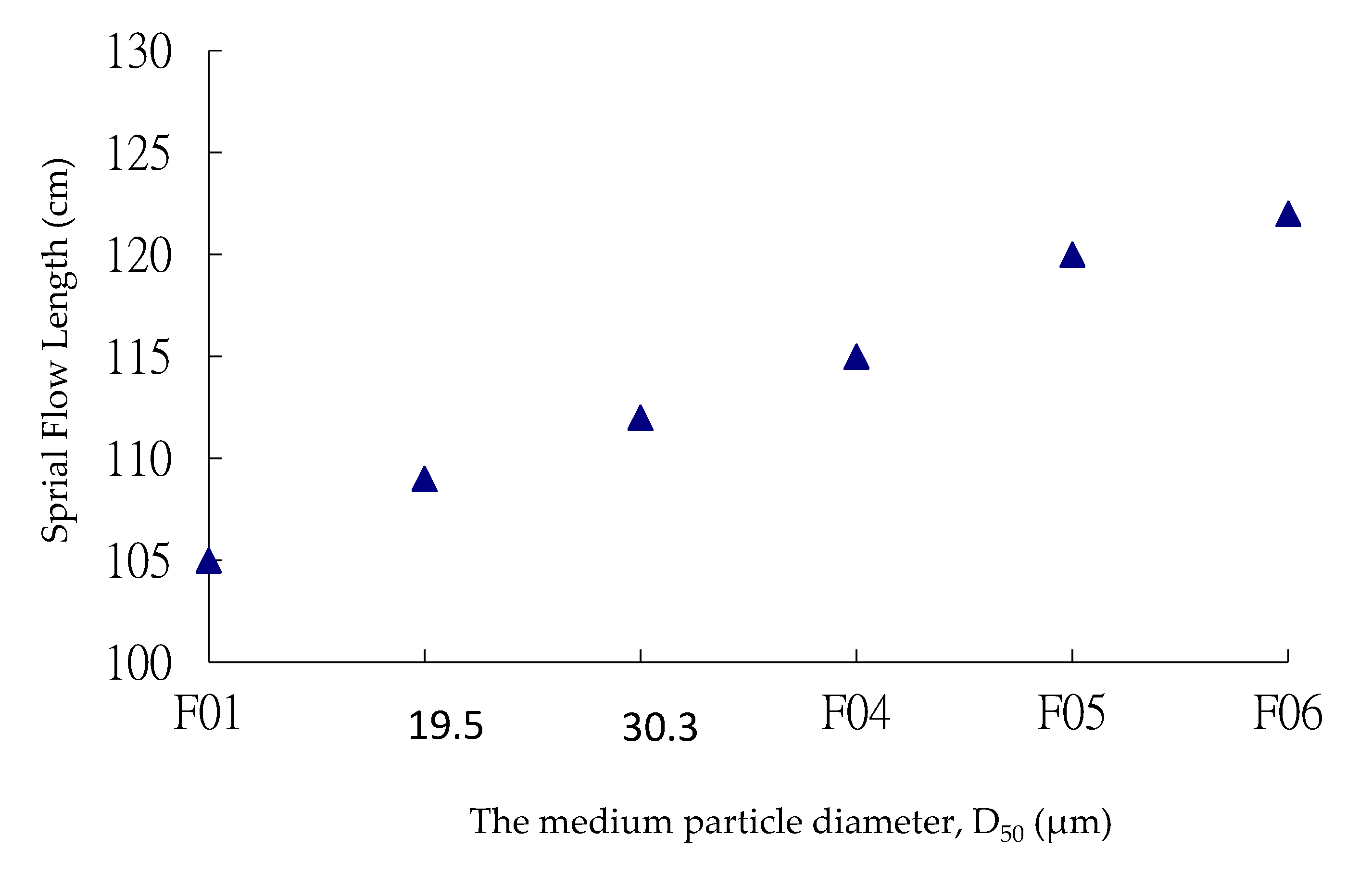
The variation of the flow spiral length versus D50 for polygonal fused silica fillers (F01 to F06) is depicted in
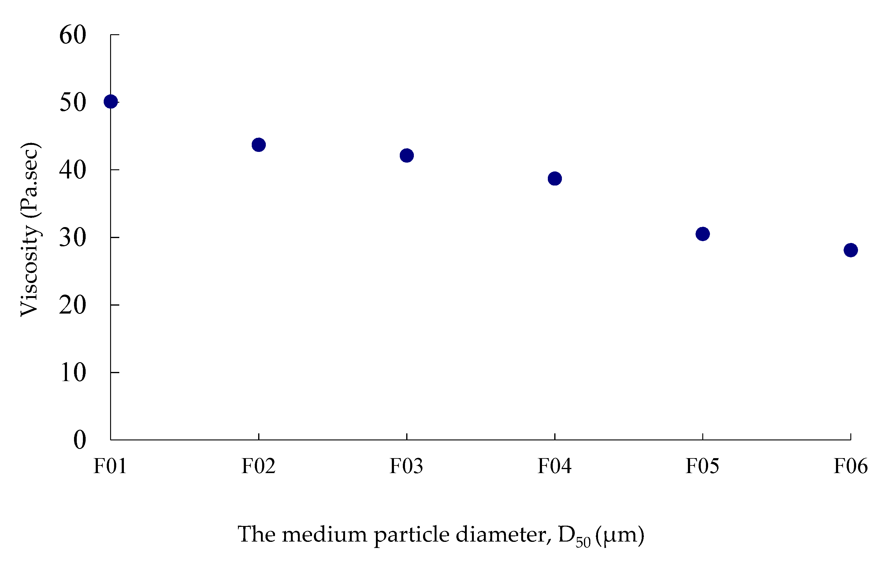
Figure 1; the data standard deviation is denoted by σ. The result clearly indicates that, for polygonal fused silica fillers, the flow spiral length increased linearly as the filler size increased, indicating that EMC flows better by increasing the filler size. This trend was further evidenced by the results of EMC viscosity portrayed in
Figure 2, which illustrates that for polygonal fused silica fillers, the EMC viscosity decreased as the filler size increased. The reason for this consistent trend in flow spiral length and viscosity is due to a smaller SSA as the filler size increased and thus resulting in smaller friction of flow. This trend is consistent with that of [
15], which points out that the flow spiral length increased as the silica particle ratio D
L/D
S increased. The symbols D
L and D
S are the diameters of the silica fillers and silica sealing particles, respectively; a typical value of the latter was about 2 μm.
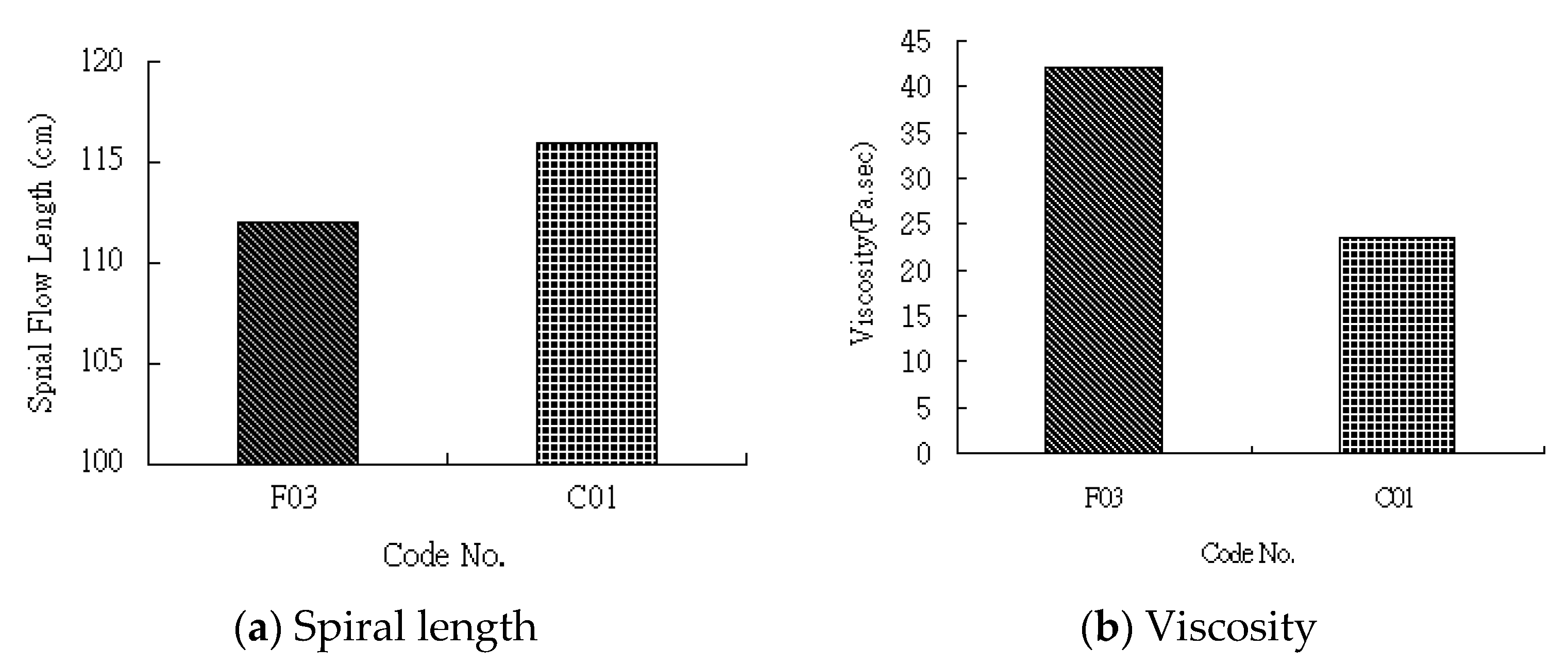
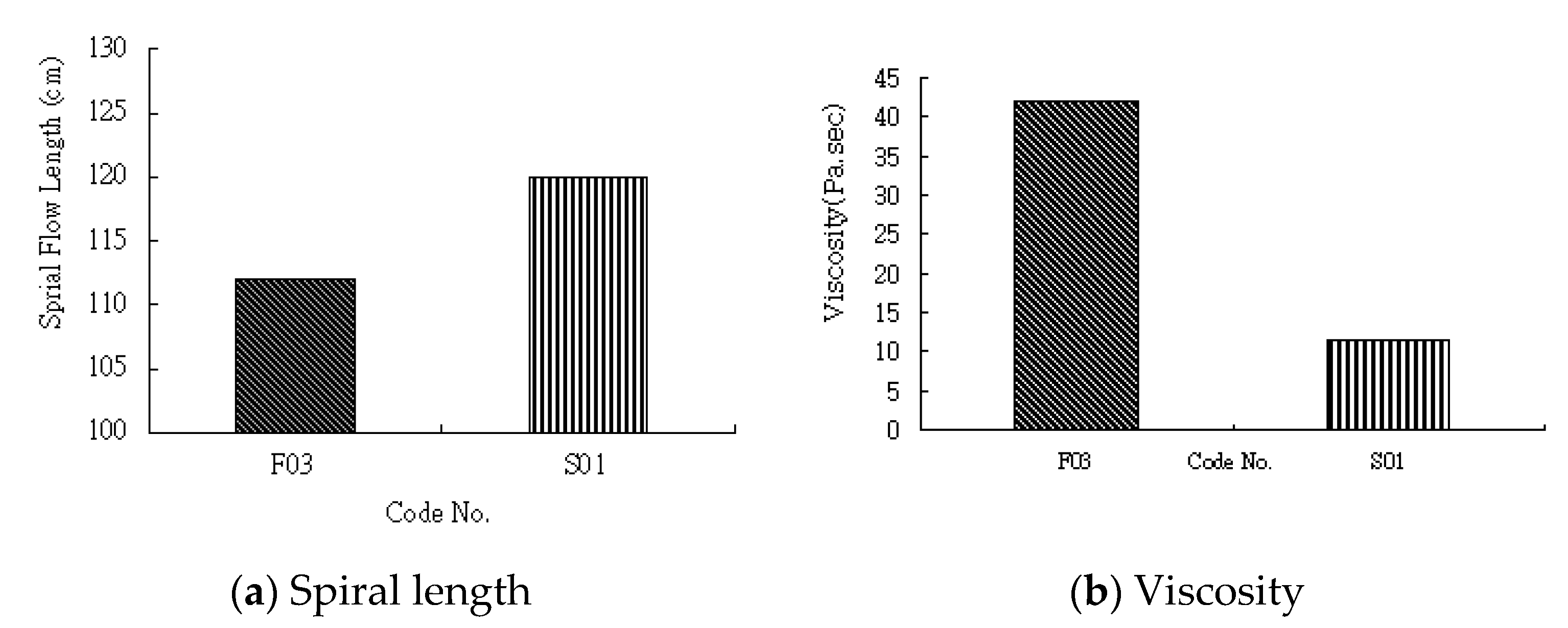
For the effect of silica types and shapes, the fillers of similar D50 were selected. For silica types, the D50 value of C01 was 22 µm, which was between those of F02 (19.5 µm) and F03 (30.3 µm). For silica shapes, the D50 value of S01 was 28.2 µm, which was close to that of F03 (30.3 µm). Hence, for simplicity, F03 was chosen for the comparison of both type and shape effects of fillers. The corresponding comparisons are shown in
Figure 3 and
Figure 4, respectively. For the silica type effect exhibited by the polygonal fused silica (F03) and polygonal crystal silica fillers (C01),
Figure 3a,b shows the comparisons of the spiral length and viscosity of the respective EMCs. The result indicates that the EMC with polygonal crystal silica fillers flowed slightly better. For the shape effect, the results portrayed in
Figure 4 shows that the EMC with spherical fused silica fillers flowed better than that with polygonal fused silica fillers.
From the results shown in both
Figure 3 and
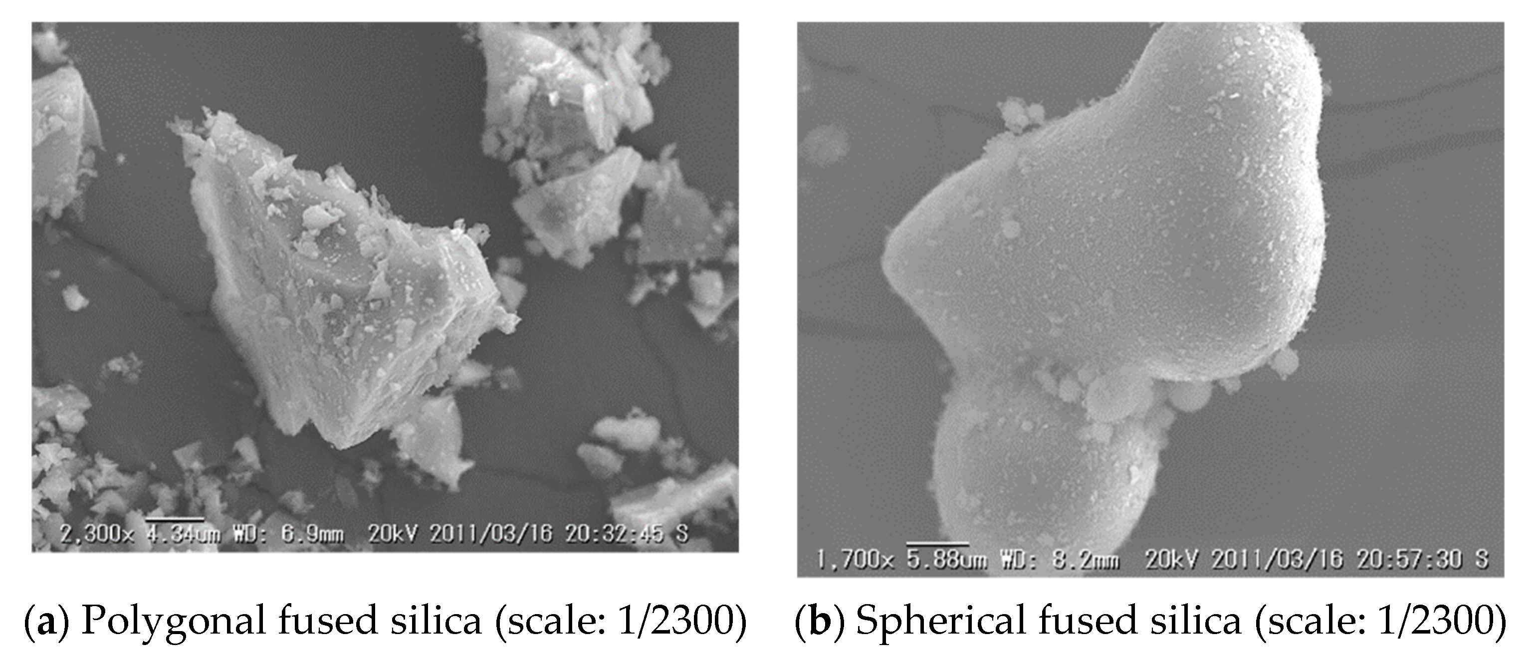
Figure 4, it is clear that the shape had a larger effect than the type on the spiral length and viscosity of EMCs. As illustrated in
Figure 5a,b, the main difference in shape between F03 and S01 was that the former was polygonal whereas the latter was spherical. The polygonal shape is multi-directional whereas the spherical shape is unidirectional; thus, the flow resistance of the latter was smaller than that of the former. This is also consistent with Mooney’s equation, which relates the Einstein constant (K
E) to the viscosity; a larger K
E leads to a larger viscosity. The K
E value of spherical particles was about 2.5 [
16], whereas it was larger for polygonal particles due to a larger aspect ratio resulting from their slender shape.
On the other hand, the difference caused by polygonal F03 and C01 was due to specific gravity. The specific gravity of polygonal fused silica (F03) was 2.2 g/cm
3, lighter than the 2.64 g/cm
3 of the polygonal crystal silica (C01) [
7]. Therefore, with conditions of the same weight and shape, the volume of F03 was larger than that of C01, as γ
fV
f = γ
cV
c, where the symbols γ and V stand for the specific gravity and volume, respectively, and the subscripts f and c denote F03 and C01, respectively. Thus, the EMC with C01 contained more epoxy and cured slower, thus leading to a longer flow spiral length and a smaller viscosity. Under similar conditions, the EMC with spherical fused silica fillers had the smallest viscosity and hence the largest flow spiral length due to its smaller flow resistance, as expected.
3.2. Thermal Conductivity
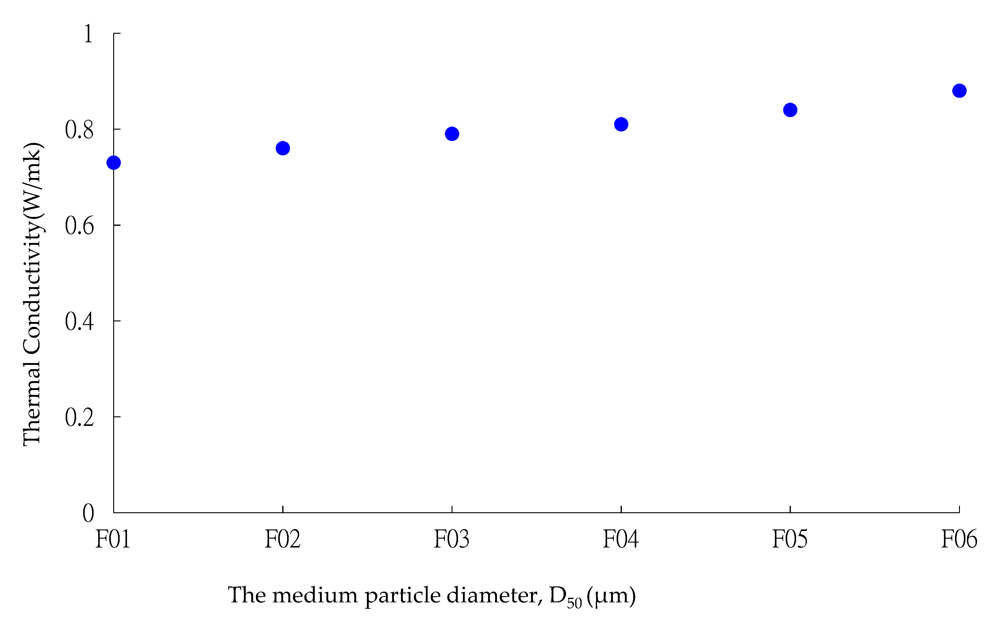
The thermal conductivity of the EMCs with fused polygonal silica fillers (F01 to F06) in terms of D50 is shown in
Figure 6. The results reveal that the thermal conductivities increased linearly and slightly as the filler size increased. Overall, as shown in
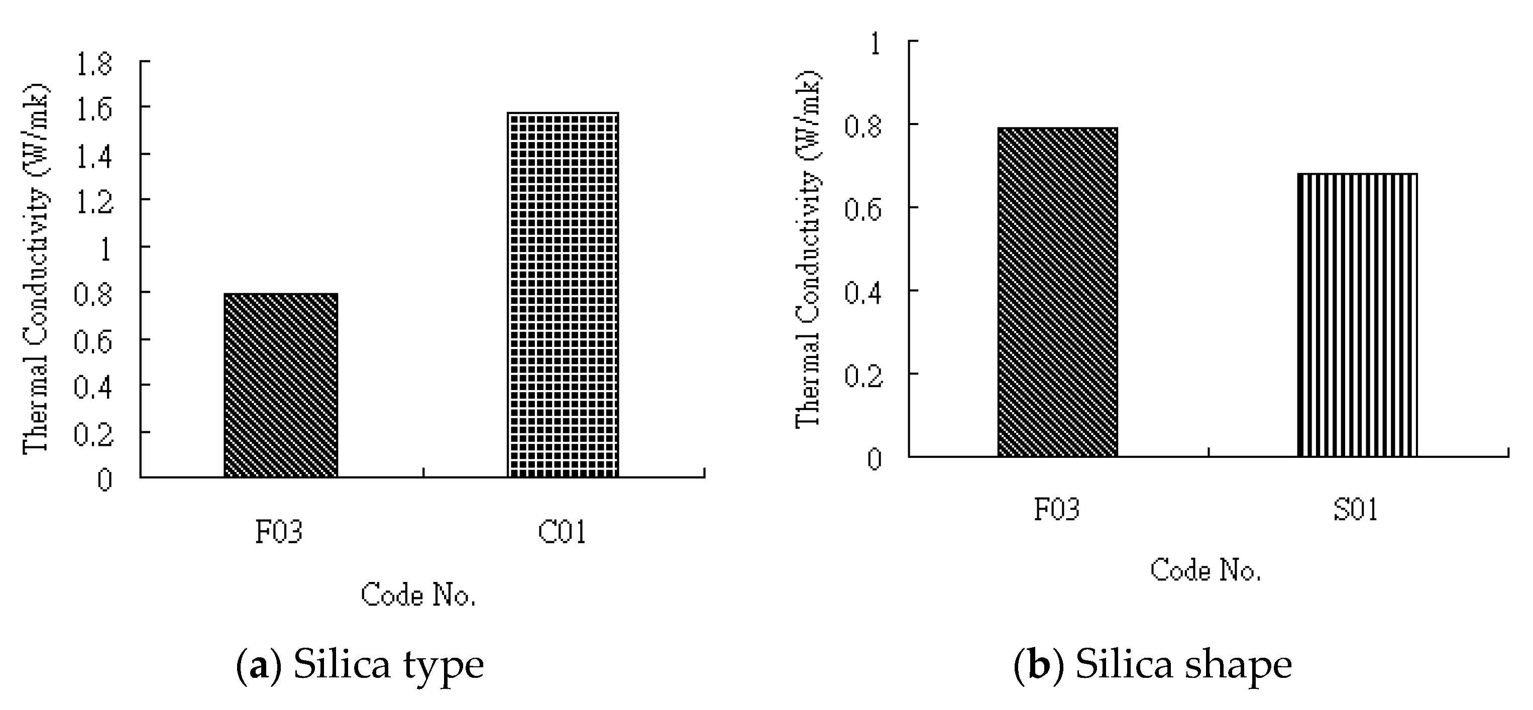
Figure 7, the EMCs with crystal silica fillers (C01) had the largest thermal conductivity, those with polygonal fused silica fillers (F03) the second, and those with spherical fused silica fillers (S01) the third.
From Hasselman’s model [
17], the thermal conductivity of the EMC composite could be evaluated by the rule of effective thermal conductivities of the individual components (i.e., resin matrix and silica filler) using the idea of an equivalent diameter of the filler particles. A larger equivalent diameter implies a larger thermal conductivity. Moreover, as the thermal conductivity of crystal silica is about 10 times that of fused silica [
9], and much larger than that of epoxy at 0.02–0.04 W/mk [
15], the model indicates that the thermal conductivity of the EMC with C01 was larger than that with F03, as illustrated in
Figure 7a.
In contrast, both F03 and S01 were fused silica of different shapes. The former was polygonal whereas the latter was spherical. The reason for the EMC with polygonal silica fillers having a larger thermal conductivity than that with the spherical silica fillers can be illustrated by the Lewis–Nielsen semi-empirical model [
18]. The model shows that the thermal conductivity depends on the particle shape factor; a larger shape factor indicates a larger thermal conductivity. The shape factor is K
E-1, where K
E is the Einstein constant (K
E = 2.5 for the spherical filler and was larger for the polygonal filler due to a larger aspect ratio, as stated previously). That is, the model indicates that the thermal conductivity of the EMC of F03 was larger than that of the EMC of S01, which is consistent with the results shown in
Figure 7b.
3.3. CTE
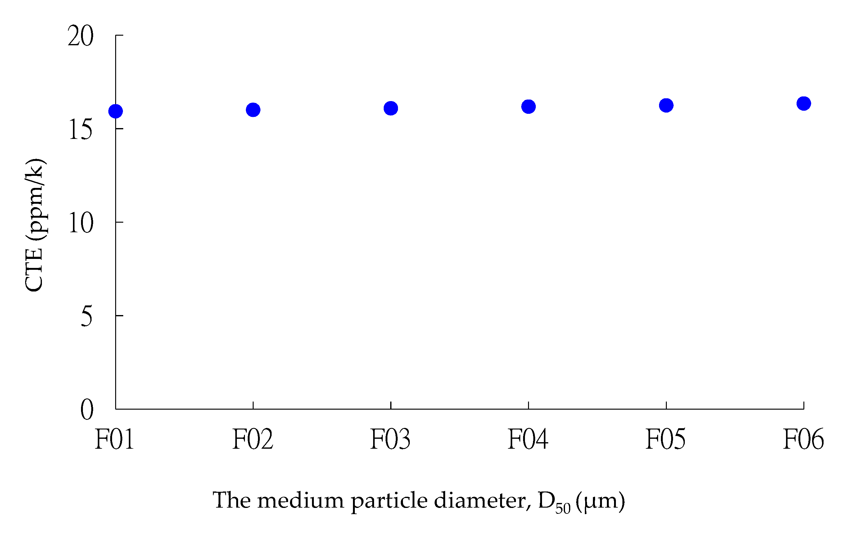
The results of the CTE of the EMCs with various fillers are shown in
Figure 8 and
Figure 9. It can be observed from
Figure 8 that for the EMCs with polygonal silica fillers (F01 to F06), CTE increased slightly and nearly linearly as the filler size increased, consistent with the observations of [
15], even though the increase was not significant. In contrast, the CTE of the EMC of C01 was about twice that of the EMC of F03, as in [
10]. On the other hand, the CTEs of the EMCs of F03 and S01 were about the same because they consisted of the same type of fused silica fillers.
The above observations indicate that the CTE depends strongly on the filler type, and slightly on the filler size, but not on the filler shape. As reducing CTE can reduce the package shrinkage [
19,
20], silica fillers can be used to adjust EMC qualities [
21]. Hence, if the shrinkage of EMC is of great concern, then fused silica fillers with a smaller CTE [
22] can be used. In addition, the viscosity of EMCs with fused silica fillers can be tuned to meet practical needs by shaping at the expense of a higher cost.
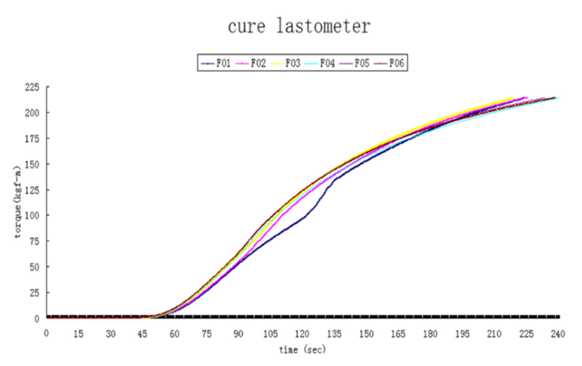
3.4. Curing Characteristics
The effect of filler sizes on curing in terms of EMC torque versus curing time is shown in
Figure 10 for EMCs with fillers of F01–F06. The results show that with polygonal fused silica fillers, filler sizes had no significant effect on the curing characteristics of the EMCs. This feature can be explained by the Kamal–Sourour equation for the degree of curing α (from 0 to 100%), as dα/dt = k
0 exp(−E/RT) α
m (1 − α)
n [
23,
24], which illustrates the relative independence of curing on particle sizes. Here, the symbols E, R, T, and t represent the activation energy, universal gas constant, absolute temperature, and time, respectively; m, n, and k
0 are constant.
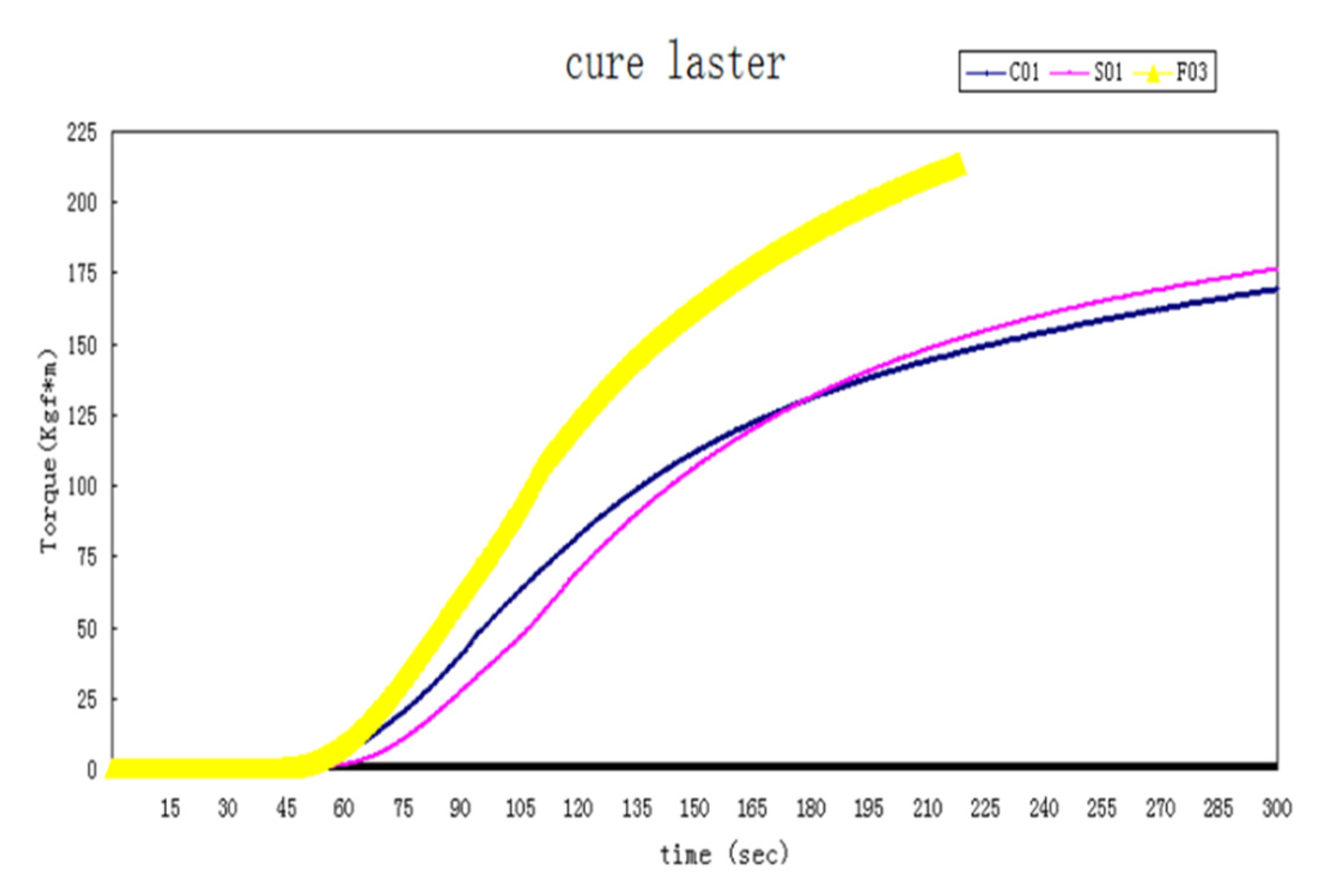
In contrast, the filler type did significantly affect EMC curing characteristics, as shown in
Figure 11. That is, the degree of curing of the EMC with fused silica fillers (F03) was considerably higher than that with crystal silica fillers (C01) due to a larger spiral flow length of the latter. In general, a larger spiral flow length, because of the smaller viscosity, led to a longer curing time.
Moreover, the filler shape also affected curing significantly by comparing the curing history of the EMCs with F03 (polygonal fused silica) and S01 (spherical fused silica). The shape effect on curing is related to the change in Tg, as shown by the DiBenedetto equation: Tg(α) = Tg
0 + ((Tg
1 − Tg
0)λα)/(1 − (1 − λ)α) [
25]. The symbols Tg
0 and Tg
1 represent the glass transition temperatures of α = 0 and 100%, respectively; λ is the shape parameter, with values that ranged between 0.2 and 0.6. Furthermore, spherical fused silica fillers had a smaller K
E from the Mooney equation [
16], thus leading to a smaller viscosity and larger spiral flow length, and resulting a longer curing time. In other words, the degree of curing α depended strongly on both filler shape and type.
It is interesting to note from
Figure 11 that the curing characteristics of EMCs with either C01 or S01 were similar for the following reason. As stated previously in
Section 3.1, crystal silica is heavier than fused silica. With the same weight percentage in the EMC, the volume of crystal silica is smaller, i.e., the resin amount is larger, hence, the EMC with crystal silica (C01) flowed better. On the other hand, spherical silica has less flow resistance due to its shape, hence, the EMC with spherical silica (S01) flowed better. These two contrasting trends of silica type and shape resulted in a similar flow behavior and led to similar curing characteristics of the EMC with fillers of either C01 or S01. Hence, these features can be utilized to tune the desired curing characteristic.
4. Conclusions
In this study, the effects of silica fillers on the properties of EMCs are examined experimentally. Key observations are as follows.
First, the viscosity, flow spiral length, and thermal conductivity of EMCs depend on the size, shape, and type of silica fillers. The EMCs with a larger filler size have a smaller viscosity and a larger flow spiral length. Spherical fillers have a lower viscosity and a larger flow spiral length due to their shape. The thermal conductivity of EMCs increases as the filler size increases. The thermal conductivity of EMCs with crystal silica is about twice that with fused silica, whereas polygonal fused silica leads to larger thermal conductivity than that of spherical fused silica.
Second, the CTE of EMCs is related to the filler size and type, but is not significantly dependent on shape. CTE increases as the filler size increases. Given that the CTE of EMCs with crystal silica is about twice that of fused silica, the filler type affects the CTE significantly.
Last, both filler type and shape affect the degree of curing significantly and can be used to tune the curing characteristics according to needs.
On the other hand, with further advances in the semiconductor fabrication towards the nanometer technology node of “More Moore,” trends of higher power dissipation and smaller bond pad pitch are expected. Moreover, the heterogeneous integration for achieving more than Moore functions by fan-out technologies requires a larger package where warpage is of great concern. Therefore, EMCs with good thermal conductivity, larger spiral flow length, and matched CTE are essential. Hence, further studies for similar effects of crystal and spherical silica particles of various proportions to take advantage of their individual features would be beneficial for advanced packaging. Thus, continuous developments of both “More Moore and “More than Moore could be coped with even though the preparation of crystal and spherical silica particles is more time consuming.
Author Contributions
Conceptualization, S.C.; methodology, S.C.; software, S.C. and Y.L.; validation, Y.L.; formal analysis, S.C., Y.L., and J.-H.C.; investigation, S.C. and Y.L.; resources, J.-H.C.; data curation, S.C., Y.L., and J.-H.C.; writing—original draft preparation, Y.L.; writing—review and editing, S.C. and J.-H.C.; visualization, S.C., Y.L., and J.-H.C.; supervision, J.-H.C.; project administration, J.-H.C. All authors have read and agreed to the published version of the manuscript.
Funding
This research received no external funding.
Institutional Review Board Statement
Not applicable.
Informed Consent Statement
Not applicable.
Data Availability Statement
Data available on request due to proprietary concerns.
Conflicts of Interest
The authors declare no conflict of interest.
References
- Shen, H.-Q.; Qin, F.; Xia, G.F.; Bie, X.-R. Characterization of Thermal and Curing Behaviors of Epoxy Molding Compounds. In Proceedings of the 15th International Conference on Electronic Packaging Technology, Chengdu, China, 12–15 August 2014; pp. 369–372. [Google Scholar]
- Lu, X.; Xu, L.; Lai, H.; Du, X.; Liu, J.; Cheng, Z. Studies on Microstructure of Epoxy Molding Compound (EMC) Leadframe Interface after Environmental Aging. In Proceedings of the International Conference on Electronic Packaging Technology &High Density Packaging (ICEPT-HDP), Tsinghua University, Beijing, China, 10–13 August 2009; pp. 1051–1053. [Google Scholar]
- Nabi, H.S.; Schweitzer, D.; Vu, D.-K.; Weiss, I. Prediction of package delamination based on μMMT and BST experiments. In Proceedings of the 16th International Conference on Thermal. Mechanical and Multi-Physics Simulation and Experiments in Microelectronics and Microsystems, Budapest, Hungary, 19–22 April 2015; pp. 1–8. [Google Scholar]
- Xie, G.-C.; Ruan, J.-H.; Wang, Y.; Du, X.-Y.; Cheng, X.-M. Development of Green Molding Compound for High Voltage Discrete Package. In Proceedings of the 11th International Conference on Electronic Packaging Technology & High Density Packaging, Xidian University, Xi’an, China, 16–19 August 2010; pp. 148–151. [Google Scholar]
- Tan, W.; Liu, H.-J.; Goh, K.-S.; Liu, H.-J.; Cheng, X.-M. Toughness Improvement Study of Epoxy Molding Compound. In Proceedings of the 11th International Conference on Electronic Packaging Technology & High Density Packaging, Xidian University, Xi’an, China, 16–19 August 2010; pp. 145–147. [Google Scholar]
- Moon, K.S.; Hwang, S.-D.; Yoon, H.-G.; Ryu, J.-H.; Woo, S.-S. High Filler Loading Technique and Its Effects on the Reliability of Epoxy Molding Compound. In Proceedings of the 2nd Electronics Packaging Technology Conference, Raffles City Convention Center, Singapore, 10 December 1998; pp. 318–324. [Google Scholar]
- Tan, T.H.; Mogi, N.; Yeoh, L.P. Development of Environmental Friendly (Green), Thermally Enhanced Mold Compound (TEMC) for Advance Packages. In Proceedings of the Int’l Symp on Electronic Materials & Packaging (EMAP), Hong Kong University, Hong Kong, China, 30 November–2 December 2000; pp. 160–166. [Google Scholar]
- Liaw, Y.C.; Chou, J.-H. The Effects of Silica Fillers on the Properties of Encapsulation Molding Compounds. ASME J. Electron. Packag. 2017, 139, 031007-1–031007-6. [Google Scholar] [CrossRef]
- Bujard, P.; Kuhnlein, G.; Ino, S.; Shiobara, T. Thermal Conductivity of Molding Compounds for Plastic Packaging. IEEE Trans. Compon. Packag. Manuf. Technol. Part. A 1994, 17, 527–532. [Google Scholar] [CrossRef]
- Procter, P.; Solc, J. Improved Thermal Conductivity in Microelectronic Encapsulants. IEEE Trans. Compon. Hybrids Manuf. Technol. 1991, 14, 835–842. [Google Scholar] [CrossRef]
- Yao, Y.-Y.; Lu, G.-Q.; Boroyevich, D.; Ngo, K.D.T. Survey of High-Temperature Polymeric Encapsulants for Power Electronics Packaging. IEEE Trans. Compon. Packag. Manuf. Technol. 2015, 5, 168–181. [Google Scholar]
- Schindler-Saefkow, F.; Rost, F.; Rezaie-Adli, A.; Jansen, K.M.B.; Wunderle, B.; Keller, J.; Rzepkal, S.; Michell, B. Measuring the Mechanical Relevant Shrinkage During In-Mold and Post-Mold Cure with the Stress Chip. In Proceedings of the 15th International Conference on Thermal, Mechanical and Multi-Physics Simulation and Experiments in Microelectronics and Microsystems, Ghent, Belgium, 7–9 April 2014; pp. 1–5. [Google Scholar]
- Palczynska, A.; Gromala, P.J.; Mayerb, D.; Han, B.; Melz, T. In-Situ Investigation of EMC Relaxation Behavior Using Piezoresistive Stress Sensor. In Proceedings of the 16th International Conference on Thermal, Mechanical and Multi-Physics Simulation and Experiments in Microelectronics and Microsystems, Budapest, Hungary, 19–22 April 2015; pp. 1–5. [Google Scholar]
- Gromaia, P.; Muthuraman, B.; Ozturk, B.; Jansen, K.M.B.; Ernst, L. Material Characterization and Nonlinear Viscoelastic Modelling of Epoxy Based Thermosets for Automotive Application. In Proceedings of the 16th international Conference on Thermal, Mechanical and Multi-Physics Simulation and Experiments in Microelectronics and Microsystems, Budapest, Hungary, 19–22 April 2015; pp. 1–7. [Google Scholar]
- Bae, J.-W.; Kim, W.; Cho, S.-H.; Lee, S.-H. The Properties of AIN-Filled Epoxy Molding Compounds by the Effects of Filler Size Distribution. J. Mater. Sci. 2000, 35, 5907–5913. [Google Scholar] [CrossRef]
- Alger, M. Einstein equation. In Polymer Science Dictionary, 2nd ed.; Chapman &Hall: London, UK, 1997; p. 168. [Google Scholar]
- Hasselman, D.; Johnson, L. Effective Thermal Conductivity of Composites with Interfacial Thermal Barrier Resistance. J. Compos. Mater. 1987, 21, 508–515. [Google Scholar] [CrossRef]
- Michael, M.; Nguyen, L. Effect of Mold Compound Thermal Conductivity in IC Package Thermal Performance. In Proceedings of the InterSociety Conference on Thermal Phenomena in Electronic systems, Austin, TX, USA, 5–8 February 1992; pp. 246–252. [Google Scholar]
- Mengel, M.; Mahler, J. Impact of Reaction Shrinkage on Stress in Semiconductor Packages. J. Electron. Mater. 2009, 38, 2362–2367. [Google Scholar] [CrossRef]
- Yang, D.G.; Jansen, K.M.B.; Ernst, L.J.; Zhang, G.Q.; Bressers, H.J.L.; Janssen, J.H.J. Effect of Filler Concentration of Rubbery Shear and Bulk Modulus of Molding Compounds. Microelectron. Reliab. 2007, 47, 233–239. [Google Scholar] [CrossRef]
- Han, J.T.; Cho, K. Nanoparticle-Induced Enhancement in Fracture Toughness of Highly Loaded Epoxy Composites over a Wide Temperature Range. J. Mater. Sci. 2006, 41, 4239–4245. [Google Scholar] [CrossRef]
- Chen, A.S.; Lo, R.H.Y. Highly Thermally Conductive, Low Stress Molding Compounds. In Proceedings of the 46th Electronic Components and Technology Conference (ECTC), IEEE, Institute of Electrical and Electronics Engineers, Inc. Staff, Orlando, FL, USA, 28–31 May 1996; pp. 599–604. [Google Scholar]
- Jansen, K.M.B.; Wang, L.; van’t Hof, C.; Ernst, L.J.; Bressers, H.J.L.; Zhang, G.Q. Cure, Temperature and Time Dependent Constitutive Modeling of Moulding Compounds. In Proceedings of the 5th International Conference on Thermal and Mechanical Simulation and Experiments in Micro-electronics and Micro-Systems, Brussels, Belgium, 10–12 May 2004; pp. 581–585. [Google Scholar]
- Jansen, K.M.B.; Qian, C.; Ernst, L.J.; Bohm, C.; Kessler, A.; Preu, H.; Stecher, M. Kinetic Characterization of Molding Compounds. In Proceedings of the 8th International Conference on Thermal, Mechanical and Multi-Physics Simulation Experiments in Microelectronics and Micro-Systems, London, UK, 16–18 April 2007; pp. 1–5. [Google Scholar]
- Ahmad, Z.; Sarwar, M.I.; Mark, J.E. Dynamic–Mechanical Thermal Analysis of Aramid–Silica, Hybrid Composites Prepared in Sol-Gel Process. J. Appl. Polym. Sci. 1997, 63, 1345–1352. [Google Scholar] [CrossRef]
| Publisher’s Note: MDPI stays neutral with regard to jurisdictional claims in published maps and institutional affiliations. |
© 2021 by the authors. Licensee MDPI, Basel, Switzerland. This article is an open access article distributed under the terms and conditions of the Creative Commons Attribution (CC BY) license (http://creativecommons.org/licenses/by/4.0/).


